Rosemount RMCT Wireless Pressure Transmitter User Manual 2051 Wireless revAA
Rosemount Inc Wireless Pressure Transmitter 2051 Wireless revAA
User Manual
Reference Manual
00809-0100-4102, Rev AA
June 2012
Rosemount 2051 Wireless Series
Pressure, Level, and Flow Solutions with WirelessHART™
Protocol

Reference Manual
00809-0100-4102, Rev AA
Title Page
June 2012
i
Rosemount 2051 Wireless Series Scalable Pressure,
Flow, and Level Solutions
Read this manual before working with the product. For personal and system safety, and for
optimum product performance, make sure you thoroughly understand the contents before
installing, using, or maintaining this product.
For technical assistance, contacts are listed below:
Customer Central
Technical support, quoting, and order-related questions.
United States - 1-800-999-9307 (7:00 am to 7:00 pm CST)
Asia Pacific- 65 777 8211
Europe/ Middle East/ Africa - 49 (8153) 9390
North American Response Center
Equipment service needs.
1-800-654-7768 (24 hours—includes Canada)
Outside of these areas, contact your local Rosemount® representative.
The products described in this document are NOT designed for nuclear-qualified
applications. Using non-nuclear qualified products in applications that require
nuclear-qualified hardware or products may cause inaccurate readings.
For information on Rosemount nuclear-qualified products, contact your local Rosemount
Sales Representative.
ii
Reference Manual
00809-0100-4102, Rev AA
Title Page
June 2012
Failure to follow these installation guidelines could result in death or serious injury:
Make sure only qualified personnel perform the installation.
Explosions could result in death or serious injury:
Installation of this transmitter in an explosive environment must be in accordance with the
appropriate local, national, and international standards, codes, and practices. Please review
the approvals section of this manual for any restrictions associated with a safe installation.
Before connecting a Field Communicator in an explosive atmosphere, ensure the
instruments are installed in accordance with intrinsically safe or non-incendive field
wiring practices.
Verify that the operating atmosphere of the transmitter is consistent with the
appropriate hazardous locations certifications.
Process leaks could result in death or serious injury.
Install and tighten process connectors before applying pressure.
Do not attempt to loosen or remove process connectors while the transmitter is in
service.
Electrical shock can result in death or serious injury.
Avoid contact with the leads and terminals. High voltage that may be present on leads
can cause electrical shock.
The Rosemount 2051 and all other wireless devices should be installed only after the Smart
Wireless Gateway has been installed and is functioning properly. Wireless devices should
also be powered up in order of proximity from the Smart Wireless Gateway, beginning with
the closest. This will result in a simpler and faster network installation.
Shipping considerations for wireless products (Lithium Batteries: Green Power Module,
model number 701PGNKF):
The unit was shipped to you without the Power Module installed. Please remove the
Power Module from the unit prior to shipping.
Primary lithium batteries are regulated in transportation by the U. S. Department of
Transportation, and are also covered by IATA (International Air Transport Association),
ICAO (International Civil Aviation Organization), and ARD (European Ground
Transportation of Dangerous Goods). It is the responsibility of the shipper to ensure
compliance with these or any other local requirements. Please consult current
regulations and requirements before shipping.
Using the Rosmeount 3051 Wireless Pressure Transmitter in a manner other than what is
specified by the menufacturer may impair the protection provided by the equipment.

iii
Reference Manual
00809-0100-4102, Rev AA
Table of Contents
June 2012
Table of Contents
1Section 1: Introduction
1.1 Using This Manual . . . . . . . . . . . . . . . . . . . . . . . . . . . . . . . . . . . . . . . . . . . . . . . . . . . . . .1
1.2 Models Covered . . . . . . . . . . . . . . . . . . . . . . . . . . . . . . . . . . . . . . . . . . . . . . . . . . . . . . . .1
1.3 Service Support . . . . . . . . . . . . . . . . . . . . . . . . . . . . . . . . . . . . . . . . . . . . . . . . . . . . . . . .2
1.4 Product Recycling/Disposal . . . . . . . . . . . . . . . . . . . . . . . . . . . . . . . . . . . . . . . . . . . . . .3
2Section 2: Configuration
2.1 Overview . . . . . . . . . . . . . . . . . . . . . . . . . . . . . . . . . . . . . . . . . . . . . . . . . . . . . . . . . . . . . .5
2.2 Safety Messages . . . . . . . . . . . . . . . . . . . . . . . . . . . . . . . . . . . . . . . . . . . . . . . . . . . . . . . .5
2.2.1 Warnings (). . . . . . . . . . . . . . . . . . . . . . . . . . . . . . . . . . . . . . . . . . . . . . . . . . . . . . .6
2.3 Required Bench Top Configuration. . . . . . . . . . . . . . . . . . . . . . . . . . . . . . . . . . . . . . . .6
2.3.1 Connection Diagrams . . . . . . . . . . . . . . . . . . . . . . . . . . . . . . . . . . . . . . . . . . . . .6
2.4 Device Network Configuration . . . . . . . . . . . . . . . . . . . . . . . . . . . . . . . . . . . . . . . . . . .7
2.4.1 Join Device to Network . . . . . . . . . . . . . . . . . . . . . . . . . . . . . . . . . . . . . . . . . . . .7
2.4.2 Configure Update Rate . . . . . . . . . . . . . . . . . . . . . . . . . . . . . . . . . . . . . . . . . . . .8
2.4.3 Remove Power Module . . . . . . . . . . . . . . . . . . . . . . . . . . . . . . . . . . . . . . . . . . . .8
2.5 Review Configuration Data. . . . . . . . . . . . . . . . . . . . . . . . . . . . . . . . . . . . . . . . . . . . . . .9
2.5.1 Review Pressure Information . . . . . . . . . . . . . . . . . . . . . . . . . . . . . . . . . . . . . . .9
2.5.2 Review Device Information. . . . . . . . . . . . . . . . . . . . . . . . . . . . . . . . . . . . . . . . .9
2.5.3 Review Sensor Information. . . . . . . . . . . . . . . . . . . . . . . . . . . . . . . . . . . . . . . .11
2.5.4 Review Radio Information. . . . . . . . . . . . . . . . . . . . . . . . . . . . . . . . . . . . . . . . .11
2.6 Field Communicator . . . . . . . . . . . . . . . . . . . . . . . . . . . . . . . . . . . . . . . . . . . . . . . . . . .13
2.7 Check Output . . . . . . . . . . . . . . . . . . . . . . . . . . . . . . . . . . . . . . . . . . . . . . . . . . . . . . . . .14
2.7.1 Operating Parameters . . . . . . . . . . . . . . . . . . . . . . . . . . . . . . . . . . . . . . . . . . . .14
2.8 Basic Setup . . . . . . . . . . . . . . . . . . . . . . . . . . . . . . . . . . . . . . . . . . . . . . . . . . . . . . . . . . .14
2.8.1 Set Process Variable Unit. . . . . . . . . . . . . . . . . . . . . . . . . . . . . . . . . . . . . . . . . .14
2.8.2 Set Transfer Function . . . . . . . . . . . . . . . . . . . . . . . . . . . . . . . . . . . . . . . . . . . . .16
2.8.3 Damping. . . . . . . . . . . . . . . . . . . . . . . . . . . . . . . . . . . . . . . . . . . . . . . . . . . . . . . .17
2.8.4 Write Protect . . . . . . . . . . . . . . . . . . . . . . . . . . . . . . . . . . . . . . . . . . . . . . . . . . . .17
2.9 LCD Display . . . . . . . . . . . . . . . . . . . . . . . . . . . . . . . . . . . . . . . . . . . . . . . . . . . . . . . . . . .18
2.9.1 LCD Display Configuration . . . . . . . . . . . . . . . . . . . . . . . . . . . . . . . . . . . . . . . .18
2.10Detailed Setup . . . . . . . . . . . . . . . . . . . . . . . . . . . . . . . . . . . . . . . . . . . . . . . . . . . . . . . .19
2.10.1Configure Process Alarms . . . . . . . . . . . . . . . . . . . . . . . . . . . . . . . . . . . . . . . . .19
2.10.2Sensor Temperature Unit . . . . . . . . . . . . . . . . . . . . . . . . . . . . . . . . . . . . . . . . .20
2.11Diagnostics and Service . . . . . . . . . . . . . . . . . . . . . . . . . . . . . . . . . . . . . . . . . . . . . . . .20
2.11.1Master Reset . . . . . . . . . . . . . . . . . . . . . . . . . . . . . . . . . . . . . . . . . . . . . . . . . . . .20
Contents

iv
Reference Manual
00809-0100-4102, Rev AA
Table of Contents
June 2012
Table of Contents
2.11.2Join Status . . . . . . . . . . . . . . . . . . . . . . . . . . . . . . . . . . . . . . . . . . . . . . . . . . . . . 20
2.11.3Number of Available Neighbors . . . . . . . . . . . . . . . . . . . . . . . . . . . . . . . . . . . 21
2.12Advanced Functions for HART Protocol. . . . . . . . . . . . . . . . . . . . . . . . . . . . . . . . . . 22
2.12.1Saving, Recalling, and Cloning Configuration Data . . . . . . . . . . . . . . . . . . 22
3Section 3: Installation
3.1 Overview . . . . . . . . . . . . . . . . . . . . . . . . . . . . . . . . . . . . . . . . . . . . . . . . . . . . . . . . . . . . 25
3.2 Safety Messages . . . . . . . . . . . . . . . . . . . . . . . . . . . . . . . . . . . . . . . . . . . . . . . . . . . . . . 25
3.2.1 Warnings (). . . . . . . . . . . . . . . . . . . . . . . . . . . . . . . . . . . . . . . . . . . . . . . . . . . . . 26
3.3 Considerations . . . . . . . . . . . . . . . . . . . . . . . . . . . . . . . . . . . . . . . . . . . . . . . . . . . . . . . 27
3.3.1 General . . . . . . . . . . . . . . . . . . . . . . . . . . . . . . . . . . . . . . . . . . . . . . . . . . . . . . . . 27
3.3.2 Wireless. . . . . . . . . . . . . . . . . . . . . . . . . . . . . . . . . . . . . . . . . . . . . . . . . . . . . . . . 27
3.3.3 Mechanical . . . . . . . . . . . . . . . . . . . . . . . . . . . . . . . . . . . . . . . . . . . . . . . . . . . . 27
3.3.4 Environmental . . . . . . . . . . . . . . . . . . . . . . . . . . . . . . . . . . . . . . . . . . . . . . . . . 28
3.4 Installation Procedures . . . . . . . . . . . . . . . . . . . . . . . . . . . . . . . . . . . . . . . . . . . . . . . . 29
3.4.1 Mount the Transmitter. . . . . . . . . . . . . . . . . . . . . . . . . . . . . . . . . . . . . . . . . . . 29
3.4.2 Process Connections . . . . . . . . . . . . . . . . . . . . . . . . . . . . . . . . . . . . . . . . . . . . 32
3.4.3 Consider Housing Rotation . . . . . . . . . . . . . . . . . . . . . . . . . . . . . . . . . . . . . . . 34
3.4.4 Grounding . . . . . . . . . . . . . . . . . . . . . . . . . . . . . . . . . . . . . . . . . . . . . . . . . . . . . 34
3.4.5 Power Module Installation. . . . . . . . . . . . . . . . . . . . . . . . . . . . . . . . . . . . . . . . 35
3.4.6 Installing the LCD Display . . . . . . . . . . . . . . . . . . . . . . . . . . . . . . . . . . . . . . . . 35
3.5 Rosemount 304, 305 and 306 Integral Manifolds . . . . . . . . . . . . . . . . . . . . . . . . . 36
3.5.1 Rosemount 305 Integral Manifold Installation Procedure. . . . . . . . . . . . . 37
3.5.2 Rosemount 306 Integral Manifold Installation Procedure. . . . . . . . . . . . . 37
3.5.3 Rosemount 304 Conventional Manifold Installation Procedure. . . . . . . . 38
3.5.4 Manifold Operation. . . . . . . . . . . . . . . . . . . . . . . . . . . . . . . . . . . . . . . . . . . . . . 38
4Section 4: Commissioning
4.1 Safety Messages . . . . . . . . . . . . . . . . . . . . . . . . . . . . . . . . . . . . . . . . . . . . . . . . . . . . . . 43
4.1.1 Warnings (). . . . . . . . . . . . . . . . . . . . . . . . . . . . . . . . . . . . . . . . . . . . . . . . . . . . . 43
4.2 Network Status . . . . . . . . . . . . . . . . . . . . . . . . . . . . . . . . . . . . . . . . . . . . . . . . . . . . . . . 44
4.3 Verify Operation . . . . . . . . . . . . . . . . . . . . . . . . . . . . . . . . . . . . . . . . . . . . . . . . . . . . . . 44
5Section 5: Operation and Maintenance
5.1 Overview . . . . . . . . . . . . . . . . . . . . . . . . . . . . . . . . . . . . . . . . . . . . . . . . . . . . . . . . . . . . 47
5.2 Calibration . . . . . . . . . . . . . . . . . . . . . . . . . . . . . . . . . . . . . . . . . . . . . . . . . . . . . . . . . . . 47
5.2.1 Sensor Trim overview . . . . . . . . . . . . . . . . . . . . . . . . . . . . . . . . . . . . . . . . . . . . 48

v
Reference Manual
00809-0100-4102, Rev AA
Table of Contents
June 2012
Table of Contents
5.2.2 Zero Trim . . . . . . . . . . . . . . . . . . . . . . . . . . . . . . . . . . . . . . . . . . . . . . . . . . . . . . .49
5.2.3 Sensor Trim . . . . . . . . . . . . . . . . . . . . . . . . . . . . . . . . . . . . . . . . . . . . . . . . . . . . .49
5.2.4 Recall Factory Trim—Sensor Trim. . . . . . . . . . . . . . . . . . . . . . . . . . . . . . . . . . .50
5.2.5 Line Pressure Effect (Range 2 and Range 3) . . . . . . . . . . . . . . . . . . . . . . . . . .50
5.2.6 Compensating for Line Pressure (Range 4 and Range 5). . . . . . . . . . . . . . .50
5.3 LCD Screen Messages . . . . . . . . . . . . . . . . . . . . . . . . . . . . . . . . . . . . . . . . . . . . . . . . . .53
5.3.1 Startup Screen Sequence . . . . . . . . . . . . . . . . . . . . . . . . . . . . . . . . . . . . . . . . .53
5.3.2 Diagnostic button screen sequence . . . . . . . . . . . . . . . . . . . . . . . . . . . . . . . .55
5.3.3 Network diagnostic status screens . . . . . . . . . . . . . . . . . . . . . . . . . . . . . . . . .56
5.3.4 Device Diagnostic Screens . . . . . . . . . . . . . . . . . . . . . . . . . . . . . . . . . . . . . . . .59
6Section 6: Troubleshooting
6.1 Overview . . . . . . . . . . . . . . . . . . . . . . . . . . . . . . . . . . . . . . . . . . . . . . . . . . . . . . . . . . . . .63
6.2 Safety Messages . . . . . . . . . . . . . . . . . . . . . . . . . . . . . . . . . . . . . . . . . . . . . . . . . . . . . . .63
6.2.1 Warnings (). . . . . . . . . . . . . . . . . . . . . . . . . . . . . . . . . . . . . . . . . . . . . . . . . . . . . .63
6.3 Disassembly Procedures . . . . . . . . . . . . . . . . . . . . . . . . . . . . . . . . . . . . . . . . . . . . . . . .67
6.3.1 Remove from Service . . . . . . . . . . . . . . . . . . . . . . . . . . . . . . . . . . . . . . . . . . . . .67
6.3.2 Remove Feature Assembly . . . . . . . . . . . . . . . . . . . . . . . . . . . . . . . . . . . . . . . .68
6.4 Reassembly Procedures . . . . . . . . . . . . . . . . . . . . . . . . . . . . . . . . . . . . . . . . . . . . . . . .69
6.4.1 Reassemble the Process Flange . . . . . . . . . . . . . . . . . . . . . . . . . . . . . . . . . . . .69
AAppendix A: Specifications and
Reference Data
A.1 Specifications . . . . . . . . . . . . . . . . . . . . . . . . . . . . . . . . . . . . . . . . . . . . . . . . . . . . . . . . .71
A.2 Performance Specifications . . . . . . . . . . . . . . . . . . . . . . . . . . . . . . . . . . . . . . . . . . . . .71
A.3 Functional Specifications . . . . . . . . . . . . . . . . . . . . . . . . . . . . . . . . . . . . . . . . . . . . . . .75
A.3.1 Range and Sensor Limits . . . . . . . . . . . . . . . . . . . . . . . . . . . . . . . . . . . . . . . . . .75
A.4 Physical Specifications. . . . . . . . . . . . . . . . . . . . . . . . . . . . . . . . . . . . . . . . . . . . . . . . . .79
A.5 Dimensional Drawings . . . . . . . . . . . . . . . . . . . . . . . . . . . . . . . . . . . . . . . . . . . . . . . . .83
A.6 Ordering Information . . . . . . . . . . . . . . . . . . . . . . . . . . . . . . . . . . . . . . . . . . . . . . . . . .85
A.6.1 Options (Include with selected model number) . . . . . . . . . . . . . . . . . . . . . .86
A.6.2 Options (Include with selected model number) . . . . . . . . . . . . . . . . . . . . . .93
A.6.3 Options (Include with selected model number) . . . . . . . . . . . . . . . . . . . . . .98
A.6.4 Options (Include with selected model number) . . . . . . . . . . . . . . . . . . . . 105
A.6.5 Options (Include with selected model number) . . . . . . . . . . . . . . . . . . . . 110
A.6.6 Options (Include with selected model number) . . . . . . . . . . . . . . . . . . . . 115
BAppendix B: Product Certifications
B.1 Wireless Certifications. . . . . . . . . . . . . . . . . . . . . . . . . . . . . . . . . . . . . . . . . . . . . . . . 119

vi
Reference Manual
00809-0100-4102, Rev AA
Table of Contents
June 2012
Table of Contents
B.1.1 Approved manufacturing locations. . . . . . . . . . . . . . . . . . . . . . . . . . . . . . . 119
B.1.2 European directive information . . . . . . . . . . . . . . . . . . . . . . . . . . . . . . . . . . 119
B.1.3 Telecommunication compliance . . . . . . . . . . . . . . . . . . . . . . . . . . . . . . . . . 119
B.1.4 FCC and IC. . . . . . . . . . . . . . . . . . . . . . . . . . . . . . . . . . . . . . . . . . . . . . . . . . . . . 119
B.1.5 Ordinary location certification for FM . . . . . . . . . . . . . . . . . . . . . . . . . . . . . 119
B.1.6 North American certifications. . . . . . . . . . . . . . . . . . . . . . . . . . . . . . . . . . . . 120
B.1.7 CSA - Canadian Standards Association . . . . . . . . . . . . . . . . . . . . . . . . . . . . 120
B.1.8 European certifications . . . . . . . . . . . . . . . . . . . . . . . . . . . . . . . . . . . . . . . . . 120
B.1.9 Japanese Certifications. . . . . . . . . . . . . . . . . . . . . . . . . . . . . . . . . . . . . . . . . . 121
B.1.10China (NEPSI) Certifications . . . . . . . . . . . . . . . . . . . . . . . . . . . . . . . . . . . . . 121

Reference Manual
00809-0100-4102, Rev AA
Section 1: Introduction
June 2012
1
Introduction
Section 1 Introduction
Using This Manual . . . . . . . . . . . . . . . . . . . . . . . . . . . . . . . . . . . . . . . . . . . . . . . . . . . . . . . page 1
Models Covered . . . . . . . . . . . . . . . . . . . . . . . . . . . . . . . . . . . . . . . . . . . . . . . . . . . . . . . . . page 1
Service Support . . . . . . . . . . . . . . . . . . . . . . . . . . . . . . . . . . . . . . . . . . . . . . . . . . . . . . . . . page 2
Product Recycling/Disposal . . . . . . . . . . . . . . . . . . . . . . . . . . . . . . . . . . . . . . . . . . . . . . . page 3
1.1 Using This Manual
The sections in this manual provide information on installing, operating, and maintaining the
Rosemount 2051 Wireless pressure transmitter with WirelessHART™ protocol. The sections are
organized as follows:
Section 2: Configuration provides instruction on commissioning and operating 2051
Wireless transmitters. Information on software functions, configuration parameters,
and online variables is also included.
Section 3: Installation contains mechanical and electrical installation instructions.
Section 4: Commissioning contains techniques for properly commissioning the device.
Section 5: Operation and Maintenance contains operation and maintenance
techniques.
Section 6: Troubleshooting provides troubleshooting techniques for the most common
operating problems.
Appendix A: Specifications and Reference Data supplies reference and specification
data, as well as ordering information.
Appendix B: Product Certifications contains approval information.
1.2 Models Covered
The following Rosemount 2051 Pressure Transmitters are covered by this manual:
Rosemount 2051CD Differential Pressure Transmitter
Measures differential pressure up to 2000 psi (137,9 bar).
Rosemount 2051CG Gage Pressure Transmitter
Measures gage pressure up to 2000 psi (137,9 bar).
2
Reference Manual
00809-0100-4102, Rev AA
Section 1: Introduction
June 2012
Introduction
Rosemount 2051CA Absolute Pressure Transmitter
Measures absolute pressure up to 4000 psia (275,8 bar).
Rosemount 2051T Gage and Absolute Pressure Transmitter
Measures gage pressure up to 10000 psi (689,5 bar).
Rosemount 2051L Liquid Level Transmitter
Provides precise level and specific gravity measurements up to 300 psi (20,7 bar) for a wide
variety of tank configurations.
1.3 Service Support
To expedite the return process outside of the United States, contact the nearest Emerson
Process Management representative.
Within the United States, call the Emerson Process Management Instrument and Valves
Response Center using the 1-800-654-RSMT (7768) toll-free number. This center, available 24
hours a day, will assist you with any needed information or materials.
The center will ask for product model and serial numbers, and will provide a Return Material
Authorization (RMA) number. The center will also ask for the process material to which the
product was last exposed.
Individuals who handle products exposed to a hazardous substance can avoid injury if they
are informed of and understand the hazard. If the product being returned was exposed to a
hazardous substance as defined by OSHA, a copy of the required Material Safety Data Sheet
(MSDS) for each hazardous substance identified must be included with the returned goods.
Shipping considerations for wireless products (Lithium Batteries: Green Power Module,
model number 701PGNKF):
The unit was shipped to you without the Power Module installed. Please remove the Power
Module from the unit prior to shipping.
Primary lithium batteries (charged or discharged) are regulated in transportation by the U.
S. Department of Transportation, and are also covered by IATA (International Air Transport
Association), ICAO (International Civil Aviation Organization), and ARD (European Ground
Transportation of Dangerous Goods). It is the responsibility of the shipper to ensure
compliance with these or any other local requirements. Please consult current regulations
and requirements before shipping.

3
Reference Manual
00809-0100-4102, Rev AA
Section 1: Introduction
June 2012
Introduction
The Power Module contains one “D” size primary lithium/thionyl chloride battery (Green Power
Module, model number 701PGNKF). Each Power Module contains approximately 5 grams of
lithium. Under normal conditions, the Power Module materials are self-contained and are not
reactive as long as the batteries and the module integrity are maintained. Care should be taken
to prevent thermal, electrical or mechanical damage. Contacts should be protected to prevent
premature discharge. Power Module hazards remain when cells are discharged.
Power Module should be stored in a clean and dry area. For maximum battery life, storage
temperature should not exceed 30° C.
Emerson Process Management Instrument and Valves Response Center representatives will
explain the additional information and procedures necessary to return goods exposed to
hazardous substances.
1.4 Product Recycling/Disposal
Recycling of equipment and packaging should be taken into consideration and disposed of in
accordance with local and national legislation/regulations.

4
Reference Manual
00809-0100-4102, Rev AA
Section 1: Introduction
June 2012
Introduction

Reference Manual
00809-0100-4102, Rev AA
Section 2: Configuration
June 2012
5Configuration
Section 2 Configuration
Overview . . . . . . . . . . . . . . . . . . . . . . . . . . . . . . . . . . . . . . . . . . . . . . . . . . . . . . . . . . . . . . . page 5
Safety Messages . . . . . . . . . . . . . . . . . . . . . . . . . . . . . . . . . . . . . . . . . . . . . . . . . . . . . . . . . page 5
Required Bench Top Configuration . . . . . . . . . . . . . . . . . . . . . . . . . . . . . . . . . . . . . . . . . page 6
Device Network Configuration . . . . . . . . . . . . . . . . . . . . . . . . . . . . . . . . . . . . . . . . . . . . page 7
Review Configuration Data . . . . . . . . . . . . . . . . . . . . . . . . . . . . . . . . . . . . . . . . . . . . . . . page 9
Field Communicator . . . . . . . . . . . . . . . . . . . . . . . . . . . . . . . . . . . . . . . . . . . . . . . . . . . . . page 13
Check Output . . . . . . . . . . . . . . . . . . . . . . . . . . . . . . . . . . . . . . . . . . . . . . . . . . . . . . . . . . . page 14
Basic Setup . . . . . . . . . . . . . . . . . . . . . . . . . . . . . . . . . . . . . . . . . . . . . . . . . . . . . . . . . . . . . . page 14
LCD Display . . . . . . . . . . . . . . . . . . . . . . . . . . . . . . . . . . . . . . . . . . . . . . . . . . . . . . . . . . . . . page 18
Detailed Setup . . . . . . . . . . . . . . . . . . . . . . . . . . . . . . . . . . . . . . . . . . . . . . . . . . . . . . . . . . page 19
Diagnostics and Service . . . . . . . . . . . . . . . . . . . . . . . . . . . . . . . . . . . . . . . . . . . . . . . . . . page 20
Advanced Functions for HART Protocol . . . . . . . . . . . . . . . . . . . . . . . . . . . . . . . . . . . . . page 22
2.1 Overview
This section contains information on configuration and verification that should be performed
prior to installation.
Field Communicator and AMS instructions are given to perform configuration functions. For
convenience, Field Communicator fast key sequences are labeled “Fast Keys” for each software
function below the appropriate headings.
Example Software Function
2.2 Safety Messages
Procedures and instructions in this section may require special precautions to ensure the safety
of the personnel performing the operations. Information that raises potential safety issues is
indicated by a warning symbol ( ). Refer to the following safety messages before performing
an operation preceded by this symbol.
Fast Keys 1, 2, 3, etc.

6
Reference Manual
00809-0100-4102, Rev AA
Section 2: Configuration
June 2012
Configuration
2.2.1 Warnings ( )
2.3 Required Bench Top Configuration
Bench top configuration requires a Field Communicator, AMS, or any WirelessHART
Communicator. Connect the Field Communicator leads to the terminals labeled “COMM” on the
terminal block. See Figure 2-1 on page 7.
Bench top configuration consists of testing the transmitter and verifying transmitter
configuration data. 2051 Wireless transmitters must be configured before installation.
Configuring the transmitter on the bench before installation using a Field Communicator, AMS,
or any WirelessHART Communicator ensures that all network settings are working correctly.
When using a Field Communicator, any configuration changes made must be sent to the
transmitter by using the “Send” key (F2). AMS configuration changes are implemented when
the “Apply” button is clicked.
AMS Wireless Configurator
AMS is capable of connecting to devices either directly, using a HART modem, or wirelessly via
the Smart Wireless Gateway. When configuring the device, double click the device icon or right
click and select Configure.
2.3.1 Connection Diagrams
Bench Hook-up
Connect the bench equipment as shown in Figure 2-1, and turn on the Field Communicator by
pressing the ON/OFF key or log into AMS. The Field Communicator or AMS will search for a
HART-compatible device and indicate when the connection is made. If the Field Communicator
or AMS fail to connect, it indicates that no device was found. If this occurs, refer to Section 6:
Troubleshooting.
Explosions can result in death or serious injury.
Before connecting a Field Communicator in an explosive atmosphere, make sure the
instruments are installed in accordance with intrinsically safe or nonincendive field
wiring practices.
Electrical shock can result in death or serious injury.
Avoid contact with the leads and terminals. High voltage that may be present on leads
can cause electrical shock.
This device complies with Part 15 of the FCC Rules. Operation is subject to the following
conditions: This device may not cause harmful interference this device must accept any
interference received, including interference that may cause undesired operation.
This device must be installed to ensure a minimum antenna separation distance of 20cm
from all persons.
7
Reference Manual
00809-0100-4102, Rev AA
Section 2: Configuration
June 2012
Configuration
Field Hook-up
Figure 2-1 illustrates the wiring for a field hook-up with a Field Communicator or AMS. The Field
Communicator or AMS may be connected at “COMM” on the transmitter terminal block.
Figure 2-1. Field Communicator Connection
For HART communication, a 2051 WirelessHART DD is required.
2.4 Device Network Configuration
2.4.1 Join Device to Network
In order to communicate with the Smart Wireless Gateway, and ultimately the Host System, the
transmitter must be configured to communicate over the wireless network. This step is the
wireless equivalent of connecting wires from a transmitter to the host system.
1. From the Home screen, select 2: Configure.
2. Select 1: Guided Setup.
3. Select 1: Join Device to Network.
Using a Field Communicator or AMS, enter the Network ID and Join Key so that they match the
Network ID and Join Key of the Smart Wireless Gateway and other devices in the network. If the
Network ID and Join Key are not identical to those set in the Gateway, the transmitter will not
communicate with the network. The Network ID and Join Key may be obtained from the Smart
Wireless Gateway on the Setup>Network>Settings page on the web server.
Fast Keys 2, 1, 1

8
Reference Manual
00809-0100-4102, Rev AA
Section 2: Configuration
June 2012
Configuration
2.4.2 Configure Update Rate
The Update Rate is the frequency at which a new measurement is taken and transmitted over
the wireless network. This by default is 1 minute. This may be changed at commissioning, or at
any time via AMS Wireless Configurator. The Update Rate is user selectable from 8 seconds to 60
minutes.
1. From the Home screen, select 2: Configure.
2. Select 1: Guided Setup.
3. Select 2: Configure Update Rate.
When device configuration is completed, remove the Power Module and replace the housing
cover. Tighten the cover so that metal contacts metal.
2.4.3 Remove Power Module
After the sensor and network have been configured, remove the Power Module and replace the
housing cover. The Power Module should be inserted only when the device is ready to be
commissioned.
Use caution when handling the Power Module. The Power Module may be damaged if dropped
from heights in excess of 20 ft.
Fast Keys 2, 1, 2

9
Reference Manual
00809-0100-4102, Rev AA
Section 2: Configuration
June 2012
Configuration
2.5 Review Configuration Data
The following is a list of factory default configurations that can be viewed by using the Field
Communicator or AMS. Follow the steps below to review the transmitter configuration
information.
Note
Information and procedures in this section that make use of Field Communicator fast key
sequences and AMS assume that the transmitter and communication equipment are
connected, powered, and operating correctly.
2.5.1 Review Pressure Information
To view pressure information:
1. From the Home screen, select 2: Configure.
2. Select 2: Manual Setup.
3. Select 2: Pressure.
4. Select from the corresponding number to view each field:
2.5.2 Review Device Information
To view device information:
1. From the Home screen, select 2: Configure.
2. Select 2: Manual Setup.
3. Select 4: Device Information.
4. Select 3: Device.
5. Select from the corresponding number to view each field:
Fast Keys 2, 2, 2
1Unit
2Transfer Function
3Damping
4Upper Range Value
5Lower Range Value
6Maximum
7Minimum
8Minimum Span
Fast Keys 2, 2, 4, 3
1Manufacturer
2Model


11
Reference Manual
00809-0100-4102, Rev AA
Section 2: Configuration
June 2012
Configuration
2.5.3 Review Sensor Information
To view sensor information:
1. From the Home screen, select 2: Configure.
2. Select 2: Manual Setup.
3. Select 4: Device Information.
4. Select 4: Sensor.
5. Select from the corresponding number to view each field:
2.5.4 Review Radio Information
To view radio information:
1. From the Home screen, select 2: Configure.
2. Select 2: Manual Setup.
3. Select 4: Device Information.
4. Select 5: Radio.
5. Select from the corresponding number to view each field:
Fast Keys 2, 2, 4, 4
1Measurement Type
2Module Type
3Module Serial Number
4Sensor Materials
• Isolator Material
• Fill Fluid
5Process Connector
• Connector Type
• Connector Material
•O Ring Material
•Drain Vent Material
6Remote Seal
•Number of Seals
•Seal Type
• Diaphragm Material
• Seal Fill Fluid
Fast Keys 2, 2, 4, 5
1Manufacturer


13
Reference Manual
00809-0100-4102, Rev AA
Section 2: Configuration
June 2012
Configuration
2.6 Field Communicator
1. Overview
2. Configure
3. Service Tools
1. Active Alerts
2. Communication Status
3. Pressure
4. Pressure Status
5. Last Update Time
1. Join Device to Network
2. Configure Update Rate
3. Zero Trim
4. Configure Device Display
5. Configure Process Alarms
6. Basic Setup
1. Guided Setup
2. Manual Setup
3. Alert Setup
1. Wireless
2. Pressure
3. Device Temperatures
4. Device Information
5. Device Display
6. Other
1. Network ID
2. Join Device to Network
3. Broadcast Rates
4. Configure Broadcast Power Level
5. Power Mode
6. Power Source 1. Unit
2. Transfer Function
3. Damping
4. Upper Range Value
5. Lower Range Value
6. Maximum
7. Minimum
8. Minimum Span
9. Range Using Applied Value
1. Sensor Temperature
2. Electronics Temperature
1. Unit
2. Maximum
3. Minimum
1. HI-HI Alarm
2. HI Alarm
3. LO Alarm
4. LO-LO Alarm
1. Configure LO-LO Alarm
2. Mode
3. Variable
4. Alarm Direction
5. Alarm Limit
6. Dead Band
1. Configure LO Alarm
2. Mode
3. Variable
4. Alarm Direction
5. Alarm Limit
6. Dead Band
1. Configure HI-HI Alarm
2. Mode
3. Variable
4. Alarm Direction
5. Alarm Limit
6. Dead Band
1. Configure HI Alarm
2. Mode
3. Variable
4. Alarm Direction
5. Alarm Limit
6. Dead Band
1. Mode
2. Display Options
1. Measurement and
Status Log
1. Alerts
2. Variables
3. Communications
4. Routine Maintenance
5. Simulate
1. Active Alerts
2. History
1. Percent of Range
2. Pressure
3. Pressure Status
4. Sensor Temperature
5. Sensor Temperature Status
6. Electronics Temperature
7. Electronics Temp Status
8. Supply Voltage
9. Supply Voltage Status
10. Last Update Time
1. Join Status
2. Communication Status
3. Join Mode
4. Number of Available
Neighbors
5. Number of Advertisements
Heard
6. Number of Join Attempts
1. Sensor Calibration
2. Other
1. Current Lower Trim
2. Current Upper Trim
3. Zero Sensor Trim
4. Lower Sensor Trim
5. Upper Sensor Trim
6. Recall Factory Trim
1. Master Reset
2. Measurement History
3. Advertise to New Devices
1. Pressure
2. Sensor Temperature
3. Electronics Temperature
4. Supply Voltage
1. Tag
2. Long Tag
3. Device
4. Sensor
5. Radio
6. Write Protect
1. Manufacturer
2. Model
3. Final Assembly Number
4. Universal
5. Field Device
6. Software
7. Hardware
8. Descriptor
9. Message
10. Date
11. Model Number I
12. Model Number II
13. Model Number III
14. SI Unit Restriction
15. Country
16. Device ID
1. Measurement Type
2. Module Type
3. Module Serial Number
4. Sensor Materials
5. Process Connector
6. Remote Seal
1. Isolator Fluid
2. Fill Fluid
1. Number of Seals
2. Seal Type
3. Diaphragm Material
4. Seal Fill Fluid
1. Connector Type
2. Connector Material
3. O Ring Material
4. Drain Vent Material
1. Manufacturer
2. Device Type
3. Device Revision
4. Software Revision
5. Hardware Revision
1. Configure Update Rate
2. Message 1
3. Message 2

14
Reference Manual
00809-0100-4102, Rev AA
Section 2: Configuration
June 2012
Configuration
2.7 Check Output
Before performing other transmitter operations, ensure that the transmitter is operating
properly by checking the operating parameters.
2.7.1 Operating Parameters
The pressure output value in both engineering units and percent of range will reflect the applied
pressure even when the applied pressure is outside of the configured range as long as the
applied pressure is between the upper and lower range limit of the transmitter. For example, if a
Range 2 2051T (LRL = 0 psi, URL = 150 psi) is ranged from 0 to 100 psi, an applied pressure of
150 psi will return a % of range output of 150% and an engineering output of 150 psi.
To view the Operating Parameters menu:
1. From the Home screen, select 3: Service Tools.
2. Select 2: Variables.
The Operating Parameters menu displays the following information pertaining to the device:
Percent of Range
Pressure
Pressure Status
Sensor Temperature
Sensor Temperature Status
Electronics Temperature
Electronics Temperature Status
Supply Voltage
Supply Voltage Status
Last Update Time
2.8 Basic Setup
2.8.1 Set Process Variable Unit
The PV Unit command sets the process variable units to allow you to monitor your process using
the appropriate units of measure.
To select a unit of measure for the PV:
Fast Keys 3, 2
Fast Keys 2, 2, 2, 1

15
Reference Manual
00809-0100-4102, Rev AA
Section 2: Configuration
June 2012
Configuration
1. From the Home screen, select 2: Configure.
2. Select 2: Manual Setup.
3. Select 2: Pressure.
4. Select 1: Unit to select from the following engineering units:
inH2Obar torr
inHg mbar atm
ftH2Og/cm2MPa
mmH2Okg/cm2inH2O at 4 °C
mmHg Pa mmH2O at 4 °C
psi kPa
16
Reference Manual
00809-0100-4102, Rev AA
Section 2: Configuration
June 2012
Configuration
2.8.2 Set Transfer Function
The 2051 Wireless has two output settings: Linear and Square Root. Activate the square root
output option to make output proportional to flow. As input approaches zero, the 2051
Wireless automatically switches to linear output in order to ensure a more smooth, stable
output near zero (see Figure 2-2).
From 0 to 0.6 percent of the ranged pressure input, the slope of the curve is unity (y = x). This
allows accurate calibration near zero. Greater slopes would cause large changes in output (for
small changes at input). From 0.6 percent to 0.8 percent, curve slope equals 42 (y = 42x) to
achieve continuous transition from linear to square root at the transition point.
To select the output transfer function:
1. From the Home screen, select 2: Configure.
2. Select 2: Manual Setup.
3. Select 2: Pressure.
4. Select 2: Transfer Function and choose either Linear or Square Root.
Figure 2-2. Square Root Output Transition Point
Fast Keys 2, 2, 2, 2
Sq. Root
Curve
Transition Point
Linear Section
Slope=1
Slope=42
Transition Point
Sq. Root Curve
Full Scale
Flow (%)

17
Reference Manual
00809-0100-4102, Rev AA
Section 2: Configuration
June 2012
Configuration
2.8.3 Damping
The Damping command introduces a delay in processing which increases the response time of
the transmitter; smoothing variations in output readings caused by rapid input changes. In the
2051 Wireless pressure transmitter, damping only takes effect when the device is placed in high
power refresh mode and during calibration. In normal power mode, the effective damping is 0.
Note that when the device is in high power refresh mode, battery power will be depleted rapidly.
Determine the appropriate damp setting based on the necessary response time, signal stability,
and other requirements of the loop dynamics of your system. The damping value of your device
is user selectable from 0 to 25.6 seconds.
To determine the current damping value:
1. From the Home screen, select 2: Configure.
2. Select 2: Manual Setup.
3. Select 2: Pressure.
4. Select 3: Damping.
2.8.4 Write Protect
The 2051 Wireless has a software write protect security feature.
The view write protect security settings:
1. From the Home screen, select 2: Configure.
2. Select 2: Manual Setup.
3. Select 4: Device Information.
4. Select 6: Write Protect.
Fast Keys 2, 2, 2, 3
Fast Keys 2, 2, 4, 6

18
Reference Manual
00809-0100-4102, Rev AA
Section 2: Configuration
June 2012
Configuration
2.9 LCD Display
2.9.1 LCD Display Configuration
The LCD display indicates output and abbreviated diagnostic messages.
Note
Use Rosemount Wireless LCD Part Number: 00753-9004-0002.
The LCD display features a four-line display and a bar graph. The first line of five characters
displays the output description, the second line of seven digits displays the actual value, the
third line of six characters displays engineering units and the fourth line displays “Error” when
the transmitter is in alarm. The LCD display can also display diagnostic messages. The bar graph
represents the network connectivity status.
See “LCD Screen Messages” on page 53 for more information on LCD messages.
To configure LCD display options:
1. From the Home screen, select 2: Configure.
2. Select 1: Guided Setup.
3. Select 4: Configure Device Display.
Fast Keys 2, 1, 4

19
Reference Manual
00809-0100-4102, Rev AA
Section 2: Configuration
June 2012
Configuration
2.10 Detailed Setup
2.10.1 Configure Process Alarms
Alerts allow the user to configure the transmitter to output a HART message when the
configured data point is exceeded. A process alert will be transmitted continuously if the set
points are exceeded and the alert mode is ON. An alert will be displayed on a Field
Communicator, AMS status screen or in the error section of the LCD display. The alert will reset
once the value returns within range.
Note
HI alert value must be higher than the LO alert value. Both alert values must be within the
pressure or temperature sensor limits.
Example 1: Rising Alert
Example 2: Falling Alert
To configure the process alerts, perform the following procedure:
1. From the Home screen, select 2: Configure.
2. Select 1: Guided Setup.
3. Select 5: Configure Process Alarms and follow the on-screen instructions to complete
configure of process alarms.
Fast Keys 2, 1, 5
Deadband
Assigned Value
Alert Set Point
Alert “OFF” Alert “ON” Alert “OFF”
Units of Measurement
Time
Deadband
Assigned Value
Alert Set Point
Alert “OFF” Alert “ON” Alert “OFF”
Units of Measurement
Time

20
Reference Manual
00809-0100-4102, Rev AA
Section 2: Configuration
June 2012
Configuration
2.10.2 Sensor Temperature Unit
The Sensor Temperature Unit command selects between Celsius and Fahrenheit units for the
sensor temperature. The sensor temperature output is accessible via HART only.
To select the sensor temperature unit:
1. From the Home screen, select 2: Configure.
2. Select 2: Manual Setup.
3. Select 3: Device Temperatures.
4. Select 1: Sensor Temperature.
5. Select 1: Unit to select from Celsius or Fahrenheit.
2.11 Diagnostics and Service
Diagnostics and service functions listed below are primarily for use after field installation. The
Transmitter Test feature is designed to verify that the transmitter is operating properly, and can
be performed either on the bench or in the field.
2.11.1 Master Reset
The master reset function will reset the device electronics. To perform a master reset:
1. From the Home screen, select 3: Service Tools.
2. Select 4: Routine Maintenance.
3. Select 2: Other.
4. Select 1: Master Reset.
2.11.2 Join Status
To view the join status of the device, perform the following procedure:
1. From the Home screen, select 3: Service Tools.
2. Select 3: Communications.
3. Select 1: Join Status.
Fast Keys 2, 2, 3, 1, 1
Fast Keys 3, 4, 2, 1
Fast Keys 3, 3, 1

21
Reference Manual
00809-0100-4102, Rev AA
Section 2: Configuration
June 2012
Configuration
Wireless devices join the secure network through a four step process:
Step 1. Network Found
Step 2. Network Security Clearance Granted
Step 3. Network Bandwidth Allocated
Step 4. Network Join Complete
2.11.3 Number of Available Neighbors
In a self-organizing network, the more neighbors a device has, the more robust the network will
be. To view the number of available neighbors for the wireless device, perform the following
procedure:
1. From the Home screen, select 3: Service Tools.
2. Select 3: Routine Maintenance.
3. Select 4: Number of Available Neighbors.
Fast Keys 3, 3, 4

22
Reference Manual
00809-0100-4102, Rev AA
Section 2: Configuration
June 2012
Configuration
2.12 Advanced Functions for HART Protocol
2.12.1 Saving, Recalling, and Cloning Configuration Data
Use the cloning feature of the Field Communicator or the AMS “User Configuration” feature to
configure several 2051 Wireless transmitters similarly. Cloning involves configuring a
transmitter, saving the configuration data, then sending a copy of the data to a separate
transmitter. Several possible procedures exist when saving, recalling, and cloning configuration
data. For complete instructions refer to the Field Communicator manual (publication no.
00809-0100-4276) or AMS Books Online. One common method is as follows:
Field Communicator
1. Completely configure the first transmitter.
2. Save the configuration data:
a. Select F2 SAVE from the Field Communicator HOME/ONLINE screen.
b. Ensure that the location to which the data will be saved is set to MODULE. If it is not,
select 1: Location to set the save location to MODULE.
c. Select 2: Name, to name the configuration data. The default is the transmitter tag
number.
d. Ensure that the data type is set to STANDARD. If the data type is NOT STANDARD,
select 3: Data Type to set the data type to STANDARD.
e. Select F2 SAVE.
3. Connect and power the receiving transmitter and Field Communicator.
4. Select the back arrow from the HOME/ONLINE screen. The Field Communicator menu
appears.
5. Select 1: Offline, 2: Saved Configuration, 1: Module Contents to reach the MODULE
CONTENTS menu.
6. Use the DOWN ARROW to scroll through the list of configurations in the memory
module, and use the RIGHT ARROW to select and retrieve the required configuration.
7. Select 1: Edit.
8. Select 1: Mark All.
9. Select F2 SAVE.
10. Use the DOWN ARROW to scroll through the list of configurations in the memory
module, and use the RIGHT ARROW to select the configuration again.
11. Select 3: Send to download the configuration to the transmitter.
12. Select OK after the control loop is set to manual.
13. After the configuration has been sent, select OK.
Fast Keys left arrow, 1, 2

23
Reference Manual
00809-0100-4102, Rev AA
Section 2: Configuration
June 2012
Configuration
When finished, the Field Communicator informs you of the status. Repeat Steps 3 through 13 to
configure another transmitter.
Note
The transmitter receiving cloned data must have the same software version (or later) as the
original transmitter.
AMS creating a Reusable Copy
To create a reusable copy of a configuration perform the following procedure:
1. Completely configure the first transmitter.
2. Select View then User Configuration View from the menu bar (or click the toolbar
button).
3. In the User Configuration window, right click and select New from the context menu.
4. In the New window, select a device from the list of templates shown, and click OK.
5. The template is copied into the User Configurations window, with the tag name
highlighted; rename it as appropriate and press Enter.
Note
A device icon can also be copied by dragging and dropping a device template or any other
device icon from AMS Explorer or Device Connection View into the User Configurations window.
The “Compare Configurations” window appears, showing the Current values of the copied
device on one side and mostly blank fields on the other (User Configuration) side.
6. Transfer values from the current configuration to the user configuration as appropriate
or enter values by typing them into the available fields.
7. Click Apply to apply the values, or click OK to apply the values and close the window.
AMS Applying a User Configuration
Any amount of user configurations can be created for the application. They can also be saved,
and applied to connected devices or to devices in the Device List or Plant Database.
To apply a user configuration perform the following procedure:
1. Select the desired user configuration in the User Configurations window.
2. Drag the icon onto a like device in AMS Explorer or Device Connection View. The
Compare Configurations window opens, showing the parameters of the target device
on one side and the parameters of the user configuration on the other.
3. Transfer parameters from the user configuration to the target device as desired, Click
OK to apply the configuration and close the window.


Reference Manual
00809-0100-4102, Rev AA
Section 3: Installation
June 2012
25
Installation
Section 3 Installation
Overview . . . . . . . . . . . . . . . . . . . . . . . . . . . . . . . . . . . . . . . . . . . . . . . . . . . . . . . . . . . . . . . page 25
Safety Messages . . . . . . . . . . . . . . . . . . . . . . . . . . . . . . . . . . . . . . . . . . . . . . . . . . . . . . . . . page 25
Considerations . . . . . . . . . . . . . . . . . . . . . . . . . . . . . . . . . . . . . . . . . . . . . . . . . . . . . . . . . . page 27
Installation Procedures . . . . . . . . . . . . . . . . . . . . . . . . . . . . . . . . . . . . . . . . . . . . . . . . . . . page 29
Installing the LCD Display . . . . . . . . . . . . . . . . . . . . . . . . . . . . . . . . . . . . . . . . . . . . . . . . . page 35
Rosemount 304, 305 and 306 Integral Manifolds . . . . . . . . . . . . . . . . . . . . . . . . . . . . page 36
3.1 Overview
The information in this section covers installation considerations. A Quick Installation Guide
(document number 00825-0100-4100) is shipped with every transmitter to describe basic
installation and startup procedures. Dimensional drawings for each Rosemount 2051 Wireless
variation and mounting configuration are included in Appendix A: Specifications and Reference
Data.
Field Communicator and AMS instructions are given to perform configuration functions. For
convenience, Field Communicator fast key sequences are labeled “Fast Keys” for each software
function below the appropriate headings.
3.2 Safety Messages
Procedures and instructions in this section may require special precautions to ensure the safety
of the personnel performing the operation. Information that raises potential safety issues is
indicated with a warning symbol ( ). Refer to the following safety messages before
performing an operation preceded by this symbol.

26
Reference Manual
00809-0100-4102, Rev AA
Section 3: Installation
June 2012
Installation
3.2.1 Warnings ( )
Failure to follow these installation guidelines could result in death or serious injury.
Make sure only qualified personnel perform the installation.
Explosions can result in death or serious injury.
Installation of this transmitter in an explosive environment must be in accordance with the
appropriate local, national, and international standards, codes, and practices. Please review
the approvals section of the 2051 Wireless reference manual for any restrictions associated
with a safe installation.
Before connecting a Field Communicator in an explosive atmosphere, make sure the
instruments are installed in accordance with intrinsically safe or non-incendive field
wiring practices.
Verify that the operating atmosphere of the transmitter is consistent with the
appropriate hazardous locations certifications.
Electrical shock can result in death or serious injury.
Avoid contact with the leads and terminals. High voltage may be present on leads can
cause electrical shock.
Process leaks could result in death or serious injury.
Install and tighten process connectors before applying pressure.
Do not attempt to loosen or remove process connectors while the transmitter is
in service.
Replacement equipment or spare parts not approved by Rosemount Inc. for use as spare
parts could reduce the pressure retaining capabilities of the transmitter and may render the
instrument dangerous.
Use only bolts supplied or sold by Rosemount Inc. as spare parts.
Improper assembly of manifolds to traditional flange can damage SuperModule™.
For safe assembly of manifold to traditional flange, bolts must break back plane of
flange web (i.e., bolt hold) but must not contact module housing.
The Power Module with the wireless unit contains one “D” size primary lithium/thionyl
chloride battery (Green Power Module, model number 701PGNKF). Each Power Module
contains approximately 5 grams of lithium. Under normal conditions, the Power Module
materials are self-contained and are not reactive as long as the batteries and the pack
integrity are maintained. Care should be taken to prevent thermal, electrical or mechanical
damage. Contacts should be protected to prevent premature discharge.

27
Reference Manual
00809-0100-4102, Rev AA
Section 3: Installation
June 2012
Installation
3.3 Considerations
3.3.1 General
Measurement performance depends upon proper installation of the transmitter and impulse
piping. Mount the transmitter close to the process and use a minimum of piping to achieve best
performance. Also, consider the need for easy access, personnel safety, practical field
calibration, and a suitable transmitter environment. Install the transmitter to minimize
vibration, shock, and temperature fluctuation.
3.3.2 Wireless
Power Up Sequence
The Power Module should not be installed on any wireless device until the Smart Wireless
Gateway is installed and functioning properly. Wireless devices should also be powered up in
order of proximity from the Smart Wireless Gateway beginning with the closest. This will result
in a simpler and faster network installation. Enable High Speed Operation on the Gateway to
ensure that new devices join the network faster. For more information see the Smart Wireless
Gateway Manual (Doc. No. 00809-0200-4420).
Field Communicator Connections
In order for the Field Communicator to interface with the 2051, the Power Module must be
connected.
Figure 3-1. Field Communicator Connections
3.3.3 Mechanical
Note
For steam service or for applications with process temperatures greater than the limits of the
transmitter, do not blow down impulse piping through the transmitter. Flush lines with the
blocking valves closed and refill lines with water before resuming measurement.
Note
When the transmitter is mounted on its side, position the Coplanar flange to ensure proper
venting or draining. Mount the flange as shown in Figure 3.4.2 on page 32, keeping drain/vent
connections on the bottom for gas service and on the top for liquid service.
28
Reference Manual
00809-0100-4102, Rev AA
Section 3: Installation
June 2012
Installation
3.3.4 Environmental
Access requirements and cover installation on page 29 can help optimize transmitter
performance. Mount the transmitter to minimize ambient temperature changes, vibration,
mechanical shock, and to avoid external contact with corrosive materials. Appendix A:
Specifications and Reference Data lists temperature operating limits.
Figure 3-2. Installation Flowchart
START HERE
Bench
Calibration? Field Install
No
Configure
(Section 2)
Set Units
Set Range
Points
Set Network
Parameters
Verify
Apply Pressure
Yes
Within
Specifications? Yes
No
Refer to
Section 4
Operation and
Maintenance
Check Switches
(page 34)
Mount
Transmitter
(page 29)
Install Power
Module
(pages 35–34)
Check Process
Connection
(page 32)
Trim Transmitter
for Mounting
Effects
(page 48)
Done
Review
Transmitter
Configuration
(page 7)
Confirm
Transmitter
Configuration
(page 7)

29
Reference Manual
00809-0100-4102, Rev AA
Section 3: Installation
June 2012
Installation
3.4 Installation Procedures
For dimensional drawing information refer to “Dimensional Drawings” on page 83.
Process Flange Orientation
Mount the process flanges with sufficient clearance for process connections. For safety reasons,
place the drain/vent valves so the process fluid is directed away from possible human contact
when the vents are used. In addition, consider the need for a testing or calibration input.
Housing Rotation
See “Consider Housing Rotation” on page 34.
Power Module Side of Electronics Housing
Mount the transmitter so the Power Module side is accessible. Clearance of 2.75-in. (70 mm) is
required for cover removal.
Circuit Side of Electronics Housing
Provide 0.75 in. (19 mm) of clearance for units with out an LCD display. Three inches of
clearance is required for cover removal if a meter is installed.
Cover Installation
Always ensure a proper seal by installing the electronics housing cover(s) so that polymer
contacts polymer. Use Rosemount O-rings.
3.4.1 Mount the Transmitter
Mounting Brackets
Facilitate mounting transmitter to a 2-in. pipe, or to a panel. The B4 Bracket (SST) option is
standard for use with the Coplanar and In-Line flanges. “Coplanar Flange Mounting Configura-
tions” on page 83 shows bracket dimensions and mounting configurations for the B4 option.
Options B1–B3 and B7–B9 are sturdy, epoxy/polyester-painted brackets designed for use with
the traditional flange. The B1–B3 brackets have carbon steel bolts, while the B7–B9 brackets
have stainless steel bolts. The BA and BC brackets and bolts are stainless steel. The B1/B7/BA
and B3/B9/BC style brackets support 2-inch pipe-mount installations, and the B2/B8 style
brackets support panel mounting.
Note
Most transmitters are calibrated in the horizontal position. Mounting the transmitter in any
other position will shift the zero point to the equivalent amount of liquid head caused by the
varied mounting position. To reset zero point, refer to “Sensor Trim” on page 49.
Position the antenna such that it is vertical, typically straight up (antenna may be pointed down
as well.)

30
Reference Manual
00809-0100-4102, Rev AA
Section 3: Installation
June 2012
Installation
Flange Bolts
The 2051 can be shipped with a Coplanar flange or a Traditional flange installed with four
1.75-inch flange bolts. Mounting bolts and bolting configurations for the Coplanar and
Traditional flanges can be found on page 2-6, 7. Stainless steel bolts supplied by Emerson
Process Management are coated with a lubricant to ease installation. Carbon steel bolts do not
require lubrication. No additional lubricant should be applied when installing either type of bolt.
Bolts supplied by Emerson Process Management are identified by their head markings:
Bolt Installation
Only use bolts supplied with the Rosemount 2051 or sold by Emerson Process Management as
spare parts. When installing the transmitter to one of the optional mounting brackets, torque
the bolts to 125 in-lb. (0,9 N-m). Use the following bolt installation procedure:
1. Finger-tighten the bolts.
2. Torque the bolts to the initial torque value using a crossing pattern.
3. Torque the bolts to the final torque value using the same crossing pattern.
Torque values for the flange and manifold adapter bolts are as follows:
Table 3-1. Bolt Installation
Torque Values
Bolt Material Initial Torque Value Final Torque Value
CS-ASTM-A445 Standard 300 in.-lb (34 N-m) 650 in.-lb (73 N-m)
316 SST—Option L4 150 in.-lb (17 N-m) 300 in.-lb (34 N-m)
ASTM-A-193-B7M—Option L5 300 in.-lb (34 N-m) 650 in.-lb (73 N-m)
Alloy K-500—Option L6 300 in.-lb (34 N-m) 650 in.-lb (73 N-m)
ASTM-A-453-660—Option L7 150 in.-lb (17 N-m) 300 in.-lb (34 N-m)
ASTM-A-193-B8M—Option L8 150 in.-lb (17 N-m) 300 in.-lb (34 N-m)
Carbon Steel (CS) Head Markings
B7M
316 B8M F593_
Stainless Steel (SST) Head Markings
* The last digit in the F593_ head marking may
be any letter between A and M.
F593_
KM
660
CL A
Alloy K-500 Head Marking

31
Reference Manual
00809-0100-4102, Rev AA
Section 3: Installation
June 2012
Installation
Impulse Piping
The piping between the process and the transmitter must accurately transfer the pressure to
obtain accurate measurements. There are five possible sources of error: leaks, friction loss
(particularly if purging is used), trapped gas in a liquid line, liquid in a gas line, and density
variations between the legs.
The best location for the transmitter in relation to the process pipe depends on the process
itself. Use the following guidelines to determine transmitter location and placement of impulse
piping:
Keep impulse piping as short as possible.
For liquid service, slope the impulse piping at least 1 inch per foot (8 cm per m) upward
from the transmitter toward the process connection.
For gas service, slope the impulse piping at least 1 inch per foot (8 cm per m) downward
from the transmitter toward the process connection.
Avoid high points in liquid lines and low points in gas lines.
Make sure both impulse legs are the same temperature.
Use impulse piping large enough to avoid friction effects and blockage.
Vent all gas from liquid piping legs.
When using a sealing fluid, fill both piping legs to the same level.
When purging, make the purge connection close to the process taps and purge
through equal lengths of the same size pipe. Avoid purging through the transmitter.
Keep corrosive or hot (above 250 °F [121 °C]) process material out of direct contact
with the SuperModule and flanges.
Prevent sediment deposits in the impulse piping.
Keep the liquid head balanced on both legs of the impulse piping.
Avoid conditions that might allow process fluid to freeze within the process flange.
53
Reference Manual
00809-0100-4102, Rev AA
Section 5: Operation and Maintenance
June 2012
Operation and Maintenance
5.3 LCD Screen Messages
5.3.1 Startup Screen Sequence
The following screens will display when the Power Module is first connected to the Rosemount
2051 Wireless.
All Segments On: used to visually
determine if there are any bad
segments on the LCD
Device Identification: used to
determine Device Type.
Device Information - Tag: user
entered tag which is eight
characters long - will not display if
all characters are blank
PV Screen - process pressure
X X X X X
X X X X x x x
x x x x x x
3 0 5 1
W I r e l s
A b c d e
f g h
P R E S S
5 8. 0
P S I
54
Reference Manual
00809-0100-4102, Rev AA
Section 5: Operation and Maintenance
June 2012
Operation and Maintenance
SV Screen - sensor temperature
value
TV Screen - device temperature
value
QV Screen - voltage reading at the
power supply terminals
Percent Range Screen - percent
range reading
Alert Screen - at least one alert is
present - this screen will not
display if no alerts are present
S N S R
2 5. 0 0
d e g c
D E V
2 5. 2 5
d e g c
S u p l y
7. 2 1
v o l t s
P R C N T
7. 2 1
R A N G E
a l e r t
p r e s n t

55
Reference Manual
00809-0100-4102, Rev AA
Section 5: Operation and Maintenance
June 2012
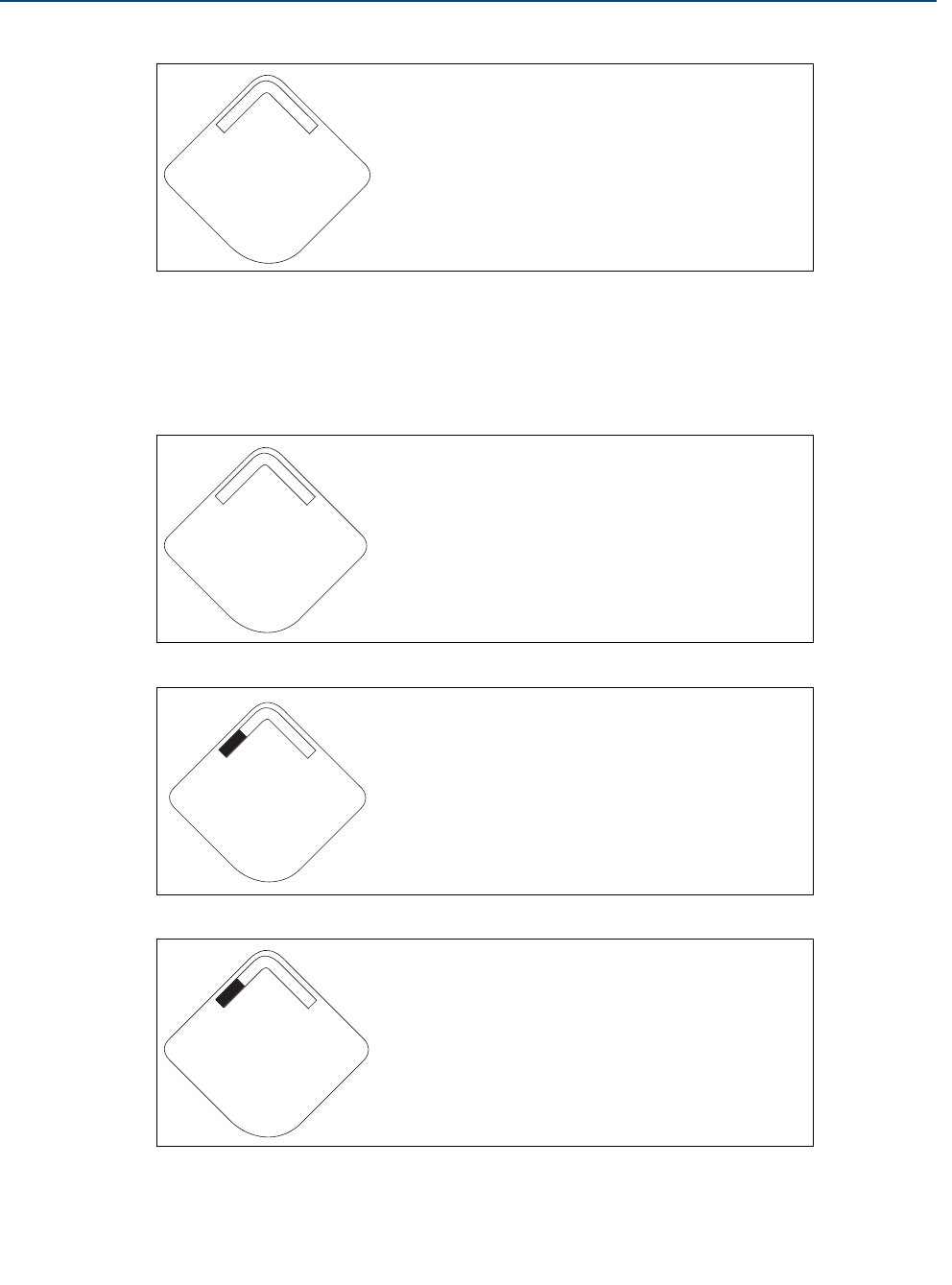
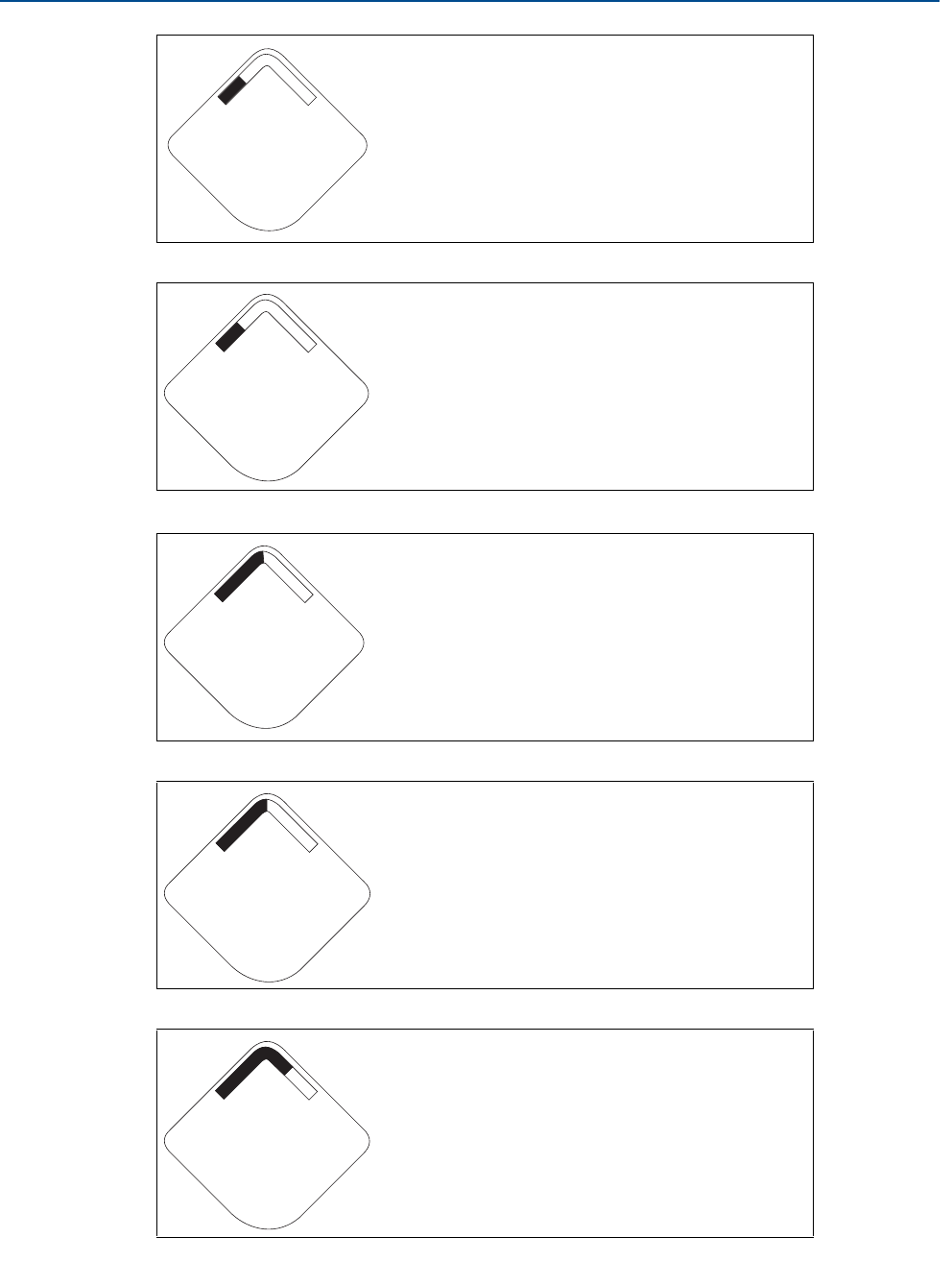
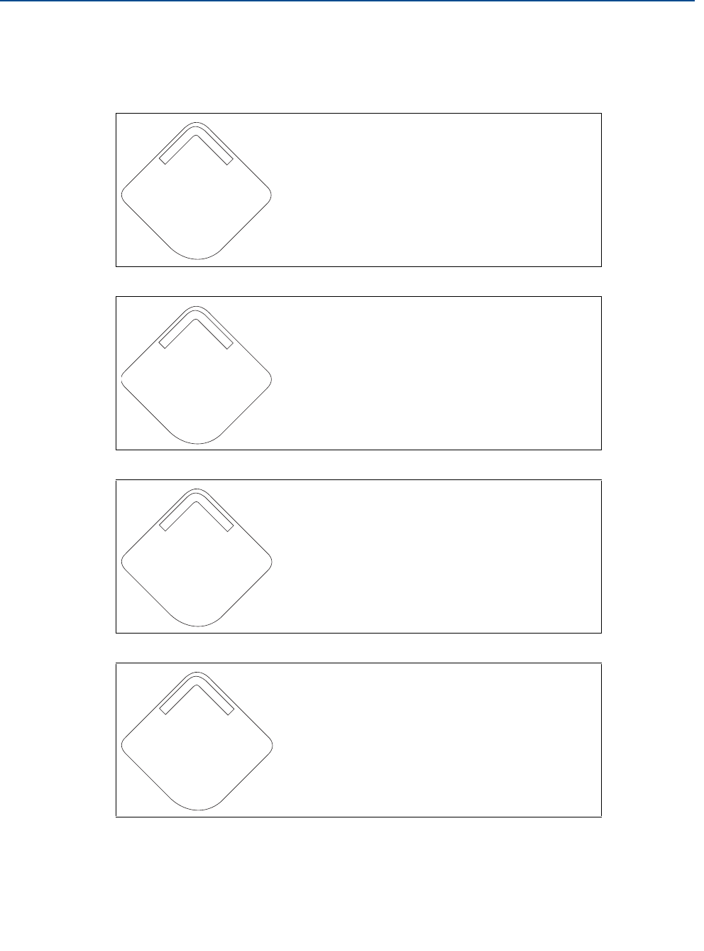
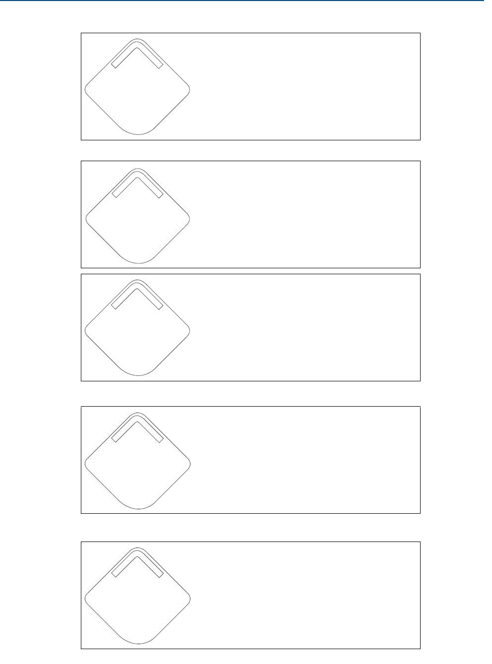
Operation and Maintenance
5.3.2 Diagnostic button screen sequence
The following five screens will display when the device is operating properly and the Diagnostic
Button has been pressed.
Device Information - Tag: user
entered tag which is eight
characters long - will not display if
all characters are blank
Device Identification: used to
determine Device ID
Diagnostic Button Screen 3:
assuming the device has the
correct join key, this ID tells the
user what network the device can
connect with
Diagnostic Button Screen 4: the device has joined a
network and has been fully configured and has
multiple parents
A b c d e
f g h
i d - 1 2
3 4 5 6 7 8
n e t w k
13 0 5
I D
n e t w k
O K
56
Reference Manual
00809-0100-4102, Rev AA
Section 5: Operation and Maintenance
June 2012
Operation and Maintenance
5.3.3 Network diagnostic status screens
These screens display the network status of the device. Only one will be shown during the
startup sequence or diagnostic sequence.
Diagnostic Button Screen 5:
voltage reading at the power
supply terminals
Diagnostic Button Screen 4.1: the device is
attempting to start the radio
Diagnostic Button Screen 4.2: the device has just
restarted
Diagnostic Button Screen 4.3: the device is starting
to join the process
S u p l y
7. 2 1
v o l t s
n e t w k
u n k n w n
n e t w k
I N I T
n e t w k
i d l e
57
Reference Manual
00809-0100-4102, Rev AA
Section 5: Operation and Maintenance
June 2012
Operation and Maintenance
Diagnostic Button Screen 4.4: the device is in a
disconnected state and requires a “Force Join”
command to join the network
Diagnostic Button Screen 4.5: the device is
searching for the Network
Diagnostic Button Screen 4.6: the device is
attempting to join a network
Diagnostic Button Screen 4.7: the device is
connected to the Network, but is in a
“Quarantined” state
Diagnostic Button Screen 4.8: the device is joined
and operational, but is running with limited
bandwidth for sending periodic data
n e t w k
D I S C N T
N E T w K
S R C H N G
n e t w k
N E G O T
n e t w k
c o n e c t
n e t w k
L I M - O P

58
Reference Manual
00809-0100-4102, Rev AA
Section 5: Operation and Maintenance
June 2012
Operation and Maintenance
Diagnostic Button Screen 4.9: the device has joined
a network and has been fully configured and has
multiple parents
n e t w k
O K
59
Reference Manual
00809-0100-4102, Rev AA
Section 5: Operation and Maintenance
June 2012
Operation and Maintenance
5.3.4 Device Diagnostic Screens
The following screens will show the device diagnostics depending on the state of the device.
Device Information - Status: there
is a critical error which may
prevent the device from
operating correctly. Check
additional status screens for more
information.
PV Screen - process pressure
value
SV Screen - sensor temperature
value
TV Screen - device temperature
value
D E V
f A i l u r
P R E S S
5 8. 0
P S I
S N S R
2 5. 0 0
d e g c
D E V
2 5. 2 5
d e g c
60
Reference Manual
00809-0100-4102, Rev AA
Section 5: Operation and Maintenance
June 2012
Operation and Maintenance
QV Screen - voltage reading at the
power supply terminals
Percent Range Screen - percent
range reading
Alert Screen - at least one alert is
present - this screen will not
display if no alerts are present
Diagnostic Button Screen 1 - Tag:
user entered tag which is eight
characters long - will not display if
all characters are blank
Diagnostic Button Screen 2: the
device’s identifier that is used to
make up the HART long address -
the Smart Wireless Gateway may
use this to help identify devices if
no unique user tag is available
S u p l y
7. 2 1
v o l t s
P R C N T
7. 2 1
R A N G E
a l e r t
p r e s n t
A b c d e
f g h
i d - 1 2
3 4 5 6 7 8

61
Reference Manual
00809-0100-4102, Rev AA
Section 5: Operation and Maintenance
June 2012
Operation and Maintenance
Diagnostic Button Screen 7.1: the
terminal voltage has dropped
below level of operating limit.
Replace the Power Module
(Part Number: 701PGNKF)
Diagnostic Button Screen 7.2: the
terminal voltage is below the
recommended operating range -
if this is a battery operated device,
the Power Module should be
replaced - for line powered
devices, the supply voltage
should be increased
Diagnostic Button Screen 8: the
device may not be able to
communicate with the radio or
the radio has an internal error. In
this state the device may still be
operational and publishing HART
data
Diagnostic Button Screen 9.1:
configuration of the transmitter is
invalid such that critical operation
of the device may be affected -
check the extended configuration
status to identify which
configuration item(s) need to be
corrected
s u p l y
f a i l u r
s u p l y
l o w
r a d i o
f a i l u r
c o n f g
f a i l u r

62
Reference Manual
00809-0100-4102, Rev AA
Section 5: Operation and Maintenance
June 2012
Operation and Maintenance
Note
Use the Rosemount Wireless LCD Part Number: 00753-9004-0002.
Diagnostic Button Screen 9.2:
configuration of the transmitter is
invalid such that non-critical
operation of the device may be
affected - check the extended
configuration status to identify
which configuration item(s) need
to be corrected
Diagnostic Button Screen 10.1: a
sensor attached to the
transmitter has failed, and valid
readings from that sensor are no
longer possible - check the sensor
and sensor wiring connections -
check additional status for more
detailed information of the failure
source
Diagnostic Button Screen 10.2: a
sensor attached to the
transmitter is degraded, readings
from that sensor may not be
within accuracy specifications -
check the process, and sensor
wiring connections - check
additional status for more
detailed information of the
warning source
c o n f g
w a r n
s n s r
f a i l u r
s n s r
w a r n
63
Reference Manual
00809-0100-4102, Rev AA
Section 6: Troubleshooting
June 2012
Troubleshooting
Section 6 Troubleshooting
Overview . . . . . . . . . . . . . . . . . . . . . . . . . . . . . . . . . . . . . . . . . . . . . . . . . . . . . . . . . . . . . . . page 63
Safety Messages . . . . . . . . . . . . . . . . . . . . . . . . . . . . . . . . . . . . . . . . . . . . . . . . . . . . . . . . . page 63
Disassembly Procedures . . . . . . . . . . . . . . . . . . . . . . . . . . . . . . . . . . . . . . . . . . . . . . . . . . page 67
Reassembly Procedures . . . . . . . . . . . . . . . . . . . . . . . . . . . . . . . . . . . . . . . . . . . . . . . . . . page 69
6.1 Overview
Table 6-2 provides summarized maintenance and troubleshooting suggestions for the most
common operating problems.
If you suspect malfunction despite the absence of any diagnostic messages on the Field
Communicator display, follow the procedures described here to verify that transmitter
hardware and process connections are in good working order. Always deal with the most likely
checkpoints first.
6.2 Safety Messages
Procedures and instructions in this section may require special precautions to ensure the safety
of the personnel performing the operations. Information that raises potential safety issues is
indicated by a warning symbol ( ). Refer to the following safety messages before performing
an operation preceded by this symbol.
6.2.1 Warnings ( )
Explosions can result in death or serious injury.
Before connecting a Field Communicator in an explosive atmosphere, make sure that
the instruments are installed according to intrinsically safe or nonincendive field
wiring practices.
Static electricity can damage sensitive components.
Observe safe handling precautions for static-sensitive components.
Electrical shock can result in death or serious injury.
Avoid contact with the leads and terminals. High voltage that may be present on leads
can cause electrical shock.
Process leaks could result in death or serious injury.
Install and tighten process connectors before applying pressure.
Do not attempt to loosen or remove process connectors while the transmitter is in
service.

64
Reference Manual
00809-0100-4102, Rev AA
Section 6: Troubleshooting
June 2012
Troubleshooting
Table 6-1. Rosemount 2051 Wireless Device Status Information
Device Status Description Recommended Action
Electronics Failure An electronics error that could
impact the device measement
reading has occurred.
1. Reset the device
2. Reconfirm all configuration items in the device
3. If the condition persists, replace the electronics
Radio Failure The wireless radio has detected a
failure or stopped communicating.
1. Reset the device
2. If the condition persists, replace the electronics
Supply Voltage
Failure The supply voltage is too low for
the device to function properly.
1. Replace the Power Module
Electronics Warning The device has detected an
electronics error that does not
currently impact the device
measurement reading.
1. Reset the device
2. Reconfirm all configuration items in the device
3. If the condition persists, replace the electronics
Pressure has
Exceeded Limits The sensor has exceeded the
maximum measurement range.
1. Check process for possible saturation condition
2. Verify that the appropriate sensor was chosen for the
application
3. Reconfirm sensor configuration
4. Reset the device
5. Replace the sensor
Electronics
Temperature has
Exceeded Limits
The electronics temperature has
exceeded the transmitter's
maximum range.
1. Verify environmental temperature is within the
transmitter’s range
2. Remote mount the transmitter away from process
and environmental conditions
3. Reset the device
4. If the condition persists, replace the electronics
Supply Voltage Low The supply voltage is low and may
soon affect broadcast updates.
1. Replace the Power Module
Database Memory
Warning The device has failed to write to
the database memory. Any data
written during this time may have
been lost.
1. Reset the device
2. Reconfirm all configuration items in the device
3. If logging dynamic data not needed, this advisory
can be safely ignored
4. If the condition persists, replace the electronics

65
Reference Manual
00809-0100-4102, Rev AA
Section 6: Troubleshooting
June 2012
Troubleshooting
Configuration Error The device has detected a
configuration error based on a
change to the device.
1. Click on details for more information
2. Correct the parameter that has a configuration error
3. Reset the device
4. If the condition persists, replace the electronics
HI HI Alarm The primary variable has surpassed
the user defined limit.
1. Verify that the process variable is within user
specified limits
2. Reconfirm the user defined alarm limit
3. If not needed, disable this alert
HI Alarm The primary variable has surpassed
the user defined limit.
1. Verify that the process variable is within user
specified limits
2. Reconfirm the user defined alarm limit
3. If not needed, disable this alert
LO Alarm The primary variable has surpassed
the user defined limit.
1. Verify that the process variable is within user
specified limits
2. Reconfirm the user defined alarm limit
3. If not needed, disable this alert
LO LO Alarm The primary variable has surpassed
the user defined limit.
1. Verify that the process variable is within user
specified limits
2. Reconfirm the user defined alarm limit
3. If not needed, disable this alert
Button Stuck A buttons on the Electronics Board
is detected as stuck in the active
position.
1. Check the buttons for obstructions
2. Reset the device
3. If the condition persists, replace the electronics
Simulation Active The device is in simulation mode
and may not be reporting actual
information.
1. Verify that simulation is no longer required
2. Disable Simulation mode in Service Tools
3. Reset the device
Device Status Description Recommended Action

66
Reference Manual
00809-0100-4102, Rev AA
Section 6: Troubleshooting
June 2012
Troubleshooting
Table 6-2. Rosemount 2051 Wireless Troubleshooting
Table 6-3. Wireless Network Troubleshooting
Symptom Recommended Actions
Transmitter will not respond to changes in
applied pressure Check test equipment
Check impulse piping or manifold for blockage
Verify applied pressure is within sensor limits
Digital Pressure Variable reading is low or
high Check test equipment (verify accuracy)
Check impulse piping for blockage or low fill in wet leg
Verify transmitter is calibrated properly
Verify pressure calculations for application
Digital Pressure Variable reading is erratic Check application for faulty equipment in pressure line
Verify transmitter is not reacting directly to equipment turning on/off
LCD display is not functioning Reseat the LCD according to “Installing the LCD Display” on page 35
Verify that the LCD display is a wireless LCD Meter. An LCD from a wired device will
not function in a wireless device. Rosemount part number: 00753-9004-0002
Verify that the LCD display mode is not disabled.
Symptom Recommended Actions
Device not joining the network Verify network ID and join key
Wait longer (30 min.)
Enable High Speed Operation on Smart Wireless Gateway
Check Power Module
Verify device is within range of at least one other device
Verify network is in active network advertise
Power Cycle device to try again
Verify device is configured to join. Send the “Force Join” command to the device
See troubleshooting section of Smart Wireless Gateway for more information
Short battery life Check that “Power Always On” mode is off
Verify device is not installed in extreme temperatures
Verfiy that device is not a network pinch point
Check for excessive network rejoins due to poor connectivity
Limited Bandwidth Error Reduce the Update Rate on transmitter
Increase communication paths by adding more wireless points
Check that device has been online for at least an hour
Check that device is not routing through a “limited” routing node
Create a new network with an additional Smart Wireless Gateway

67
Reference Manual
00809-0100-4102, Rev AA
Section 6: Troubleshooting
June 2012
Troubleshooting
6.3 Disassembly Procedures
6.3.1 Remove from Service
Be aware of the following:
Follow all plant safety rules and procedures.
Isolate and vent the process from the transmitter before removing the transmitter from
service.
Detach the process flange by removing the four flange bolts and two alignment screws
that secure it.
Do not scratch, puncture, or depress the isolating diaphragms.
Clean isolating diaphragms with a soft rag and a mild cleaning solution, and rinse with
clear water.
Whenever you remove the process flange or flange adapters, visually inspect the Teflon
o-rings. Replace the o-rings if they show any signs of damage, such as nicks or cuts. If
they are not damaged, reuse them.
The 2051 Wireless transmitter is attached to the process connection by four bolts and two cap
screws. Remove the bolts and separate the transmitter from the process connection. Leave the
process connection in place and ready for re-installation.
The 2051 Wireless In-line transmitter is attached to the process by a single hex nut process
connection. Loosen the hex nut to separate the transmitter from the process.

68
Reference Manual
00809-0100-4102, Rev AA
Section 6: Troubleshooting
June 2012
Troubleshooting
6.3.2 Remove Feature Assembly
The Wireless Feature Board is located in the electronics compartment. To remove the assembly,
perform the following procedure.
1. Remove the housing cover opposite the field terminal side.
2. Remove the LCD Display, if applicable. To do this, hold in the two clips and pull outward.
3. Loosen the two small screws located on the assembly.
4. Replace the LCD Display. This will help in removing the assembly.
5. Pull out the assembly to expose and locate the SuperModule connector and antenna
connector.
6. Grasp antenna connector by the base and pull upwards to disconnect.
7. Grasp the SuperModule connector, squeeze the clips and pull upwards
(avoid pulling wires).
Figure 6-1. Sensor module connector view
Wireless Housing

69
Reference Manual
00809-0100-4102, Rev AA
Section 6: Troubleshooting
June 2012
Troubleshooting
6.4 Reassembly Procedures
important
The V-Seal must be installed at the bottom of the housing.
6.4.1 Reassemble the Process Flange
1. Inspect the Teflon sensor module o-rings. If the o-rings are not damaged, reuse them.
Replace o-rings that show any signs of damage, such as nicks, cuts, or general wear.
Note
If you are replacing the o-rings, be careful not to scratch the o-ring grooves or the surface of the
isolating diaphragm when removing the damaged o-rings.
2. Install the process flange on the sensor module. To hold the process flange in place,
install the two alignment screws to finger tight (screws are not pressure retaining). Do
not overtighten; this will affect module-to-flange alignment.
3. Install the appropriate flange bolts.
a. If the installation requires a 1/4–18 NPT mounting, use four 1.75-in. flange bolts. Go to
Step f.
b. If the installation requires a 1/2–14 NPT mounting, use four 2.88-in. process
flange/adapter bolts. For gage pressure configurations, use two 2.88-in. bolts and two
1.75-in. bolts. Go to Step d.
c. If the installation uses a manifold (differential pressure applications only), use
appropriate bolts. Go to Step e.
d. Hold the flange adapters and adapter o-rings in place while finger-tightening the bolts.
Go to Step g.
e. Align the process flange with the manifold.
f. Finger tighten the bolts.
g. Tighten the bolts to the initial torque value using a crossed pattern. See Table 6-4 for
appropriate torque values.
h. Tighten the bolts to the final torque value using a crossed pattern. See Table 6-4 for
appropriate torque values. When fully tightened, the bolts should extend through the
top of the module housing.
i. If the installation uses a manifold, then install flange adapters on the process end of the
manifold using the 1.75-in. flange bolts supplied with the transmitter.

70
Reference Manual
00809-0100-4102, Rev AA
Section 6: Troubleshooting
June 2012
Troubleshooting
Table 6-4. Bolt Installation
Torque Values
4. If you replaced the Teflon sensor module o-rings, re-torque the flange bolts after
installation to compensate for cold flow.
5. Install the drain/vent valve.
a. Apply sealing tape to the threads on the seat. Starting at the base of the valve with the
threaded end pointing toward the installer, apply two clockwise turns of sealing tape.
b. Take care to place the opening on the valve so that process fluid will drain toward the
ground and away from human contact when the valve is opened.
c. Tighten the drain/vent valve to 250 in-lb. (28.25 N-m).
Note
After replacing o-rings on Range 1 transmitters and re-installing the process flange, expose the
transmitter to a temperature of 185 °F (85 °C) for two hours. Then re-tighten the flange bolts in
a cross pattern, and again expose the transmitter to a temperature of 185 °F (85 °C) for two
hours before calibration.
Bolt Material Initial Torque Value Final Torque Value
CS-ASTM-A445 Standard 300 in-lb. (34 N-m) 650 in-lb. (73 N-m)
316 SST—Option L4 150 in-lb. (17 N-m) 300 in-lb. (34 N-m)
ASTM-A-193-B7M—Option
L5
300 in-lb. (34 N-m) 650 in-lb. (73 N-m)
Alloy K-500—Option L6 300 in-lb. (34 N-m) 650 in-lb. (73 N-m)
ASTM-A-453-660—Option
L7
150 in-lb. (17 N-m) 300 in-lb. (34 N-m)
ASTM-A-193-B8M—Option
L8
150 in-lb. (17 N-m) 300 in-lb. (34 N-m)

Reference Manual
00809-0100-4102, Rev AA
Appendix A: Reference Data
June 2012
71Specifications and Reference Data
Appendix A Specifications and
Reference Data
Performance Specifications . . . . . . . . . . . . . . . . . . . . . . . . . . . . . . . . . . . . . . . . . . . . . . . page 71
Functional Specifications . . . . . . . . . . . . . . . . . . . . . . . . . . . . . . . . . . . . . . . . . . . . . . . . . page 75
Physical Specifications . . . . . . . . . . . . . . . . . . . . . . . . . . . . . . . . . . . . . . . . . . . . . . . . . . . page 79
Dimensional Drawings . . . . . . . . . . . . . . . . . . . . . . . . . . . . . . . . . . . . . . . . . . . . . . . . . . . page 83
Ordering Information . . . . . . . . . . . . . . . . . . . . . . . . . . . . . . . . . . . . . . . . . . . . . . . . . . . . page 85
A.1 Specifications
A.2 Performance Specifications
For zero-based spans, reference conditions, silicone oil fill, glass-filled PTFE o-rings, SST
materials, Coplanar flange (2051C) or
1/2 in.- 14 NPT (2051T) process connections, digital trim values set to equal range points.
Conformance to specification (±3 (Sigma))
Technology leadership, advanced manufacturing techniques and statistical process control
ensure specification conformance to ±3or better.
Digital Output
For wireless devices, use calibrated range in place of span.
72
Reference Manual
00809-0100-4102, Rev AA
Appendix A: Reference Data
June 2012
Specifications and Reference Data
Reference Accuracy(1)
Total Performance
Models(1)
(1) Total performance is determined by performing a root sum square calculation on reference accuracy, ambient temperature effect, and line pressure effect errors.
For FOUNDATION fieldbus transmitters, use calibrated range in place of span. For zero based spans, reference conditions, silicone oil fill, SST materials, Coplanar flange
(2051C) or 1/2 in. - 18 NPT (2051T) process connections, digital trim values set to equal range points.
Standard High Accuracy Option
2051CD,
2051CG
Range 0 (CD) ±0.10% of span
For spans less than 2:1, accuracy = ±0.05% of URL
Range 1 ±0.10% of span
For spans less than 15:1, accuracy =
Ranges 2-5 ±0.065% of span
For spans less than 10:1, accuracy = Ranges 2-4
High Accuracy Option, P8
±0.04% of span
For spans less than 5:1, accuracy =
2051T
Ranges 1-4 ±0.065% of span
For spans less than 10:1, accuracy = Ranges 1-4
High Accuracy Option, P8
±0.04% of span
For spans less than 5:1, accuracy =
Range 5 ±0.075% of span
2051CA
Ranges 1-4 ±0.065% of span
For spans less than 10:1, accuracy = Ranges 2-4
High Accuracy Option, P8
±0.04% of span
For spans less than 5:1, accuracy =
2051H/2051L
All Ranges ±0.075% of span
For spans less than 10:1, accuracy =
For ±50 °F (28 °C) temperature changes, up to 1000 psi (6,9 MPa) line pressure (CD only), from 1:1 to 5:1 rangedown.
Models Total Performance
2051C Ranges 2-5 ±0.15% of span
2051T Ranges 1-4 ±0.15% of span
0.025 0.005+URL
Span
---------------
% of Span
0.015 0.005+URL
Span
---------------
% of Span
0.015 0.005+URL
Span
---------------
% of Span
0.0075 URL
Span
---------------
% of Span
0.0075 URL
Span
---------------
% of Span
0.0075 URL
Span
---------------
% of Span
0.0075 URL
Span
---------------
% of Span
0.025 0.005+URL
Span
---------------
% of Span
73
Reference Manual
00809-0100-4102, Rev AA
Appendix A: Reference Data
June 2012
Specifications and Reference Data
Long Term Stability
Dynamic Performance
Line Pressure Effect per 1000 psi (6,9 MPa)(1)
Models Long Term Stability
2051C Ranges 2-5 ±0.125% of URL for 5 years
±50 °F (28 °C) temperature changes, and up to 1000 psi (6,9 MPa) line pressure.
2051CD Low/Draft
Range Ranges 0-1 ±0.2% of URL for 1 year
2051T Ranges 1-4 ±0.125% of URL for 5 years
±50 °F (28 °C) temperature changes, and up to 1000 psi (6,9 MPa) line pressure.
4 - 20 mA
(HART
protocol)(1)
Fieldbus
protocol(3) Typical HART Transmitter Response Time
Total Response Time (Td + Tc)(2):
2051C, Ranges 2-5:
Range 1:
Range 0:
2051T:
2051H/L:
100 ms
255 ms
700 ms
100 ms
Consult factory
152 ms
307 ms
752 ms
152 ms
Consult factory
Dead Time (Td) 45 ms (nominal) 97 ms
Update Rate 22 times per
second 22 times per
second
(1) Dead time and update rate apply to all models and ranges; analog output only
(2) Nominal total response time at 75 °F (24 °C) reference conditions.
(3) Transmitter fieldbus output only, segment macro-cycle not included.
Models(1)
(1) For zero error specifications for line pressures above 2000 psi (137,9 bar) or line pressure effect specifications for DP Ranges 4-5, see “Compensating for
Line Pressure (Range 4 and Range 5)” on page 50.
Line Pressure Effect
2051CD Zero Error(2)
±0.125% of URL/100 psi (6,89 bar)
(2) Can be calibrated out at line pressure.
Range 0
Range 1 ±0.25% of URL/1000 psi (68,9 bar)
Ranges 2-3 ±0.05% of URL/1000 psi (68,9 bar) for line pressures from 0 to 2000 psi (0 to 13,7 MPa)
Range 0
Span Error
±0.15% of reading/100 psi (6,89 bar)
Range 1 ±0.4% of reading/1000 psi (68,9 bar)
Ranges 2-3 ±0.1% of reading/1000 psi (68,9 bar)
2051HD Zero Error(1)
±0.1% of URL/1000 psi (68,9 bar) for line pressures from 0 to 2000 psi (0 to 13,7 MPa)
All Ranges
All Ranges
Span Error
±0.1% of reading/1000 psi (68,9 bar)
Tc
Td
Td = Dead Time
Tc = Time Constant
Pressure Released
Response Time = Td+Tc
63.2% of Total
Step Change
Time
0%
100%
36.8%
Transmitter Output vs. Time

74
Reference Manual
00809-0100-4102, Rev AA
Appendix A: Reference Data
June 2012
Specifications and Reference Data
Ambient Temperature Effect per 50°F (28°C)
Mounting Position Effects
Vibration Effect
Less than ±0.1% of URL when tested per the requirements of IEC60770-1 field or pipeline with
high vibration level (10-60 Hz 0.21mm displacement peak amplitude / 60-2000 Hz 3g).
Power Supply Effect
Less than ±0.005% of calibrated span per volt.
Electromagnetic Compatibility (EMC)
Meets all relevant requirements of EN 61326 and NAMUR NE-21.
Transient Protection (Option Code T1)
Meets IEEE C62.41, Category Location B
6 kV crest (0.5 s - 100 kHz)
3 kV crest (8 × 20 microseconds)
6 kV crest (1.2 × 50 microseconds)
Models Ambient Temperature Effect
2051CD/CG Range 0 ±(0.25% URL + 0.05% span)
Range 1 ±(0.1% URL + 0.25% span)
Ranges 2-5 ±(0.0125% URL + 0.0625% span) from 1:1 to 5:1
±(0.025% URL + 0.125% span) from 5:1 to 100:1
2051T Range 1 ±(0.025% URL + 0.125% span) from 1:1 to 10:1
±(0.05% URL + 0.125% span) from 10:1 to 100:1
Range 2-4 ±(0.025% URL + 0.125% span) from 1:1 to 30:1
±(0.035% URL + 0.125% span) from 30:1 to 100:1
Range 5 ±(0.1% URL + 0.15% span)
2051CA All Ranges ±(0.025% URL + 0.125% span) from 1:1 to 30:1
±(0.035% URL + 0.125% span) from 30:1 to 100:1
2051L See Rosemount Inc. Instrument Toolkit® software.
Models Mounting Position Effects
2051C Zero shifts up to ±1.25 inH2O (3,11 mbar), which can be calibrated out. No span effect.
2051L With liquid level diaphragm in vertical plane, zero shift of up to 1 inH2O (2,49 mbar). With
diaphragm in horizontal plane, zero shift of up to 5 inH2O (12,43 mbar) plus extension length on
extended units. All zero shifts can be calibrated out. No span effect.
2051T/CA Zero shifts up to 2.5 inH2O (6,22 mbar), which can be calibrated out. No span effect.

75
Reference Manual
00809-0100-4102, Rev AA
Appendix A: Reference Data
June 2012
Specifications and Reference Data
A.3 Functional Specifications
A.3.1 Range and Sensor Limits
Zero and Span Adjustment Requirements
(HART and Low Power)
Zero and span values can be set anywhere within the range limits stated in Table A-1.
Span must be greater than or equal to the minimum span stated in Table A-1.
Service
Liquid, gas, and vapor applications
4–20 mA (Output Code A)
Output
Two-wire 4–20 mA, user-selectable for linear or square root output. Digital process variable
superimposed on 4–20 mA signal, available to any host that conforms to the HART protocol.
Power Supply
External power supply required. Standard transmitter (4–20 mA) operates on 10.5 to 55 V dc with
no load.
Table A-1. 2051CD, 2051CG, 2051L, and 2051H Range and Sensor Limits
Range
Minimum Span Range and Sensor Limits
2051CD(1),
CG, L, H
(1) Range 0 only available with 2051CD. Range 1 only available with 2051CD or 2051CG.
Upper
(URL)
Lower (LRL)
2051C
Differential
2051C/
Gage
2051L
Differential
2051L
Gage
2051H
Differential
00.1 inH2O
(0,25 mbar)
3.0 inH2O
(7,47 mbar)
–3.0 inH2O
(-7,47 mbar)
NA NA NA NA
10.5 inH2O
(1,2 mbar)
25 inH2O
(62,3 mbar)
–25 inH2O
(–62,1 mbar)
–25 inH2O
(–62,1 mbar)
NA NA NA
22.5 inH2O
(6,2 mbar)
250 inH2O
(0,62 bar)
–250 inH2O
(–0,62 bar)
–250 inH2O
(–0,62 bar)
–250 inH2O
(–0,62 bar)
–250 inH2O
(–0,62 bar)
–250 inH2O
(–0,62 bar)
310 inH2O
(24,9 mbar)
1000 inH2O
(2,49 bar)
–1000 inH2O
(–2,49 bar)
0.5 psia
(34,5 mbar abs)
–1000 inH2O
(–2,49 bar)
0.5 psia
(34,5 mbar abs)
–1000 inH2O
(–2,49 bar)
43 psi
(0,20 bar)
300 psi
(20,6 bar)
–300 psi
(–20,6 bar)
0.5 psia
(34,5 mbar abs)
–300 psi
(–20,6 bar)
0.5 psia
(34,5 mbar abs)
–300 psi
(–20,6 bar)
520 psi
(1,38 bar)
2000 psi
(137,9 bar)
– 2000 psi
(–137,9 bar)
0.5 psia
(34,5 mbar abs)
NA NA – 2000 psi
(–137,9 bar)
76
Reference Manual
00809-0100-4102, Rev AA
Appendix A: Reference Data
June 2012
Specifications and Reference Data
Load Limitations
Maximum loop resistance is determined by the voltage level of the external power supply, as
described by:
Wireless Self-Organizing Networks
Output
WirelessHART, 2.4 GHz DSSS.
Local Display
The optional five-digit LCD can display user-selectable information such as primary variable in
engineering units, percent of range, sensor module temperature, and electronics temperature.
Display updates at up to once per minute.
Update Rate
User selectable, 1 sec. to 60 min.
Overpressure Limits
Transmitters withstand the following limits without damage:
Wireless Power Module
Field replaceable, keyed connection eliminates the risk of incorrect installation,
Intrinsically Safe Lithium-thionyl chloride Power Module (Green Power Module,
model number 701PGNKF) with polybutadine terephthalate (PBT) enclosure.
Ten-year life at one minute update rate.(1)
(1) Reference conditions are 70 °F (21 °C), and routing data for three additional network devices.
NOTE: Continuous exposure to ambient temperature limits of
-40 °F or 185 °F (-40 °C or 85 °C) may reduce specified life by less than 20 percent.
Voltage (V dc)
Load (Ohms)
Communication requires a minimum
loop resistance of 250 ohms.
(1) For CSA approval, power supply must not exceed 42.4 V.
Max. Loop Resistance = 43.5 (Power Supply Voltage – 10.5)
Operating
Region

77
Reference Manual
00809-0100-4102, Rev AA
Appendix A: Reference Data
June 2012
Specifications and Reference Data
Rosemount 2051CD/CG
Range 0: 750 psi (51,7 bar)
Range 1: 2000 psig (137,9 bar)
Ranges 2–5: 3626 psig (250 bar)
4500 psig (310,3 bar) for option code P9
Rosemount 2051CA
Range 1: 750 psia (51,7 bar)
Range 2: 1500 psia (103,4 bar)
Range 3: 1600 psia (110,3 bar)
Range 4: 6000 psia (413,7 bar)
Rosemount 2051H
All Ranges: 3626 psig (25 MPa)
Rosemount 2051TG/TA
Range 1: 750 psi (51,7 bar)
Range 2: 1500 psi (103,4 bar)
Range 3: 1600 psi (110,3 bar)
Range 4: 6000 psi (413,7 bar)
Range 5: 15000 psi (1034,2 bar)
Rosemount 2051L
Limit is flange rating or sensor rating, whichever is lower (see the table below).
Static Pressure Limit
Rosemount 2051CD Only
Operates within specifications between static line pressures of 0.5 psia and 3626 psig (4500 psig
(310, 3 bar) for
Option Code P9).
Range 0: 0.5 psia and 750 psig (3, 4 bar and 51, 7 bar)
Range 1: 0.5 psia and 2000 psig (3, 4 bar and 137, 9 bar)
Standard Type CS Rating SST Rating
ANSI/ASME Class 150 285 psig 275 psig
ANSI/ASME Class 300 740 psig 720 psig
ANSI/ASME Class 600 1480 psig 1440 psig
At 100 °F (38 °C), the rating decreases
with increasing temperature, per ANSI/ASME B16.5.
DIN PN 10–40 40 bar 40 bar
DIN PN 10/16 16 bar 16 bar
DIN PN 25/40 40 bar 40 bar
At 248 °F (120 °C), the rating decreases with increasing temperature, per DIN 2401.
78
Reference Manual
00809-0100-4102, Rev AA
Appendix A: Reference Data
June 2012
Specifications and Reference Data
Burst Pressure Limits
Coplanar or traditional process flange
10000 psig (689,5 bar).
2051T:
Ranges 1–4: 11000 psi (758,4 bar)
Range 5: 26000 psig (1792,64 bar)
Temperature Limits
Ambient
Storage
–40 to 185 °F (–40 to 85 °C)
With LCD display: –40 to 185 °F (–40 to 85 °C)
Process Temperature Limits
At atmospheric pressures and above.
–40 to 185 °F (–40 to 85 °C)
With LCD display(1): –40 to 175 °F (–40 to 80 °C)
(1) LCD display may not be readable and LCD updates will be slower at temperatures below -4 °F (-20 °C).
2051C Coplanar
Silicone Fill Sensor(1)
with Coplanar Flange –40 to 250 °F (–40 to 121 °C)(2)
with Traditional Flange –40 to 300 °F (–40 to 149 °C)(2)(3)
with Level Flange –40 to 300 °F (–40 to 149 °C)(2)
with 305 Integral
Manifold –40 to 300 °F (–40 to 149 °C)(2)(3)
Inert Fill Sensor(1) -40 to 185 °F (–40 to 85 °C)(4) (5)
2051T In-Line (Process Fill Fluid)
Silicone Fill Sensor(1) –40 to 250 °F (–40 to 121 °C)(2)
Inert Fill Sensor(1) –22 to 250 °F (–30 to 121 °C)(2)
2051L Low-Side Temperature Limits
Silicone Fill Sensor(1) –40 to 250 °F (–40 to 121 °C)(2)
Inert Fill Sensor(1) 0 to 185 °F (–18 to 85 °C)(2)
2051L High-Side Temperature Limits
(Process Fill Fluid)
Syltherm® XLT –102 to 302 °F (–75 to 150 °C)
D. C.® Silicone 704(6) 32 to 400 °F (0 to 205 °C)
D. C. Silicone 200 –49 to 400 °F (–45 to 205 °C)
Inert (Halocarbon) –49 to 320 °F (–45 to 160 °C)
Glycerin and Water 5 to 203 °F (–15 to 95 °C)
Neobee M-20®5 to 400 °F (–15 to 205 °C)

79
Reference Manual
00809-0100-4102, Rev AA
Appendix A: Reference Data
June 2012
Specifications and Reference Data
Humidity Limits
0–100% relative humidity
Volumetric Displacement
Less than 0.005 in3 (0,08 cm3)
Damping
The Damping command introduces a delay in processing which increases the response time of
the transmitter; smoothing variations in output readings caused by rapid input changes. In the
2051 Wireless pressure transmitter, damping only takes effect when the device is placed in high
power refresh mode and during calibration. In normal power mode, the effective damping is 0.
Note that when the device is in high power refresh mode, battery power will be depleted rapidly.
A.4 Physical Specifications
Electrical Connections
1/2–14 NPT, G1/2, and M20 x 1.5 (CM20) conduit. HART interface connections fixed to terminal
block.
Process Connections
2051C
1/4–18 NPT on 21/8-in. centers
1/2–14 NPT and RC 1/2 on 2-in. (50.8 mm), 21/8-in. (54.0 mm), or 21/4-in. (57.2 mm) centers
(process adapters)
2051T
1/2–14 NPT female,
Non-Threaded instrument flange (available in SST for Range 1–4 transmitters only),
G1/2 A DIN 16288 Male (available in SST for Range 1–4 transmitters only), or
Autoclave type F-250-C (Pressure relieved 9/16–18 gland thread; 1/4 OD high pressure tube 60°
cone; available in SST for Range 5 transmitters only).
Propylene Glycol and
Water 5 to 203 °F (–15 to 95 °C)
(1) Process temperatures above 185 °F (85 °C) require derating the ambient limits by a 1.5:1 ratio.
(2) 220 °F (104 °C) limit in vacuum service; 130 °F (54 °C) for pressures below 0.5 psia.
(3) -20 °F (-29 °C) is the lower process temperature limit with option code P0.
(4) 160 °F (71 °C) limit in vacuum service.
(5) Not available for 2051_CA.
(6) Upper limit of 600 °F (315 °C) is available with 1199 seal assemblies mounted away from the transmitter
with the use of capillaries and up to 500 °F (260 °C) with direct mount extension.
2051C Coplanar

80
Reference Manual
00809-0100-4102, Rev AA
Appendix A: Reference Data
June 2012
Specifications and Reference Data
2051L
High pressure side: 2-in.(50.8mm), 3-in. (72 mm), or 4-in. (102mm), ASME B 16.5 (ANSI) Class
150, 300 or 600 flange; 50, 80 or 100 mm, DIN 2501 PN 40 or 10/16 flange
Low pressure side: 1/4–18 NPT on flange, 1/2–14 NPT on process adapter
Process-Wetted Parts
Process Isolating Diaphragms
Drain/Vent Valves
316 SST, Alloy C-276, or Alloy 400/K-500 material
(Alloy 400/K-500 is not available with 2051L).
Process Flanges and Adapters
Plated carbon steel
SST: CF-8M (Cast 316 SST) per ASTM A743
Cast C-276: CW-12MW per ASTM A494
Cast Alloy 400: M-30C per ASTM A494
Wetted O-rings
Glass-filled PTFE
(Graphite-filled PTFE with Isolating Diaphragm code 6)
2051L Process Wetted Parts
Flanged Process Connection (Transmitter High Side)
Process Diaphragms, Including Process Gasket Surface
316L SST, Alloy C-276, or Tantalum
Extension
CF-3M (Cast 316L SST, material per ASTM A743), or CW-12MW (Cast C-276, material ASTM
A494); fits schedule 40 and 80 pipe
Mounting Flange
Zinc-cobalt plated CS or 316 SST
Isolating Diaphragm
Material
2051CD/CG
2051T
2051CA
2051H
316L SST • • • •
Alloy C-276 • • • •

81
Reference Manual
00809-0100-4102, Rev AA
Appendix A: Reference Data
June 2012
Specifications and Reference Data
Reference Process Connection (Transmitter Low Side)
Isolating Diaphragms
316L SST or Alloy C-276
Reference Flange and Adapter
CF-8M (Cast version of 316 SST, material per ASTM-A743)
Non-Wetted Parts
Electronics Housing
Low-copper aluminum alloy or SST: CF-3M (Cast 316L SST) or CF-8M (Cast 316 SST)
NEMA 4X, IP66/68
Coplanar Sensor Module Housing
CF-3M (Cast version of 316L SST)
Bolts
Plated carbon steel per ASTM A449, Type 1
Austenitic 316 SST per ASTM F593
ASTM A453, Class D, Grade 660 SST
ASTM A193, Grade B7M alloy steel
ASTM A193, Class 2, Grade B8M SST
Alloy K-500
Sensor Module Fill Fluid
Silicone or inert halocarbon (Inert is not available with 2051CA). In-Line series uses Fluorinert®
FC-43.
Process Fill Fluid (Liquid Level Only)
2051L: Syltherm XLT, D.C. Silicone 704,
D.C. Silicone 200, inert, glycerin and water,
Neobee M-20, propylene glycol and water.
Paint
Polyurethane
Cover O-rings
Buna-N
Power Module
Field replaceable, keyed connection eliminates the risk of incorrect installation, Intrinsically Safe
Lithium-thionyl chloride Power Module (Green Power Module, model number 701PGNKF) with
PBT enclosure

82
Reference Manual
00809-0100-4102, Rev AA
Appendix A: Reference Data
June 2012
Specifications and Reference Data
Shipping Weights for 2051 Wireless Pressure Transmitter
Table A-2. Transmitter weights without options
Table A-3. 2051L weights without options
Transmitter option weights
Complete Transmitter(1)
(1) Fully functional transmitter with terminal block, covers, and SST flange.
Add Weight In lb (kg)
2051C with engineered polymer
housing 3.90 (1,8)
2051T with engineered polymer
housing 2.3 (1,0)
Flange
Flush
lb. (kg)
2-in. Ext.
lb (kg)
4-in. Ext.
lb (kg)
6-in. Ext.
lb (kg)
2-in., 150 6.1 (2,8) — — —
3-in., 150 12.3 (5,6) 13.0 (5,9) 14.2 (6,4) 15.5 (7,0)
4-in., 150 17.8 (8,1) 17.5 (7,9) 18.7 (8,4) 20.0 (9,1)
2-in., 300 7.9 (3,6) — — —
3-in., 300 16.2 (7,3) 16.9 (7,7) 18.1 (8,2) 19.4 (8,8)
4-in., 300 27 (12,2) 26.9 (12,2) 28.1 (12,7) 29.4 (13,3)
2-in., 600 9.4 (4,3) — — —
3-in., 600 18.7 (8,5) 19.4 (8,8) 20.6 (9,3) 21.9 (9,9)
DN 50 / PN 40 7.9 (3,6) — — —
DN 80 / PN 40 12.6 (5,7) 13.3 (6,0) 14.5 (6,6) 15.8 (7,2)
DN 100 / PN 10/16 7.8 (3,5) 8.5 (3,9) 9.7 (4,4) 11.0 (5,0)
DN 100 / PN 40 9.2 (4,2) 9.9 (4,5) 11.1 (5,0) 12.4 (5,6)
Option Code Option Add lb (kg)
B4 SST Mounting Bracket for Coplanar Flange 1.2 (0,5)
B1, B2, B3 Mounting Bracket for Traditional Flange 1.7 (0,8)
B7, B8, B9 Mounting Bracket for Traditional Flange with SST Bolts 1.7 (0,8)
BA, BC SST Bracket for Traditional Flange 1.6 (0,7)
B4 SST Mounting Bracket for In-Line 1.3 (0,6)
F12, F22 SST Traditional Flange with SST Drain Vents(1)
(1) Includes mounting bolts.
3.2 (1,5)
F13, F23 Cast C-276 Traditional Flange with Alloy C-276 Drain Vents(1) 3.6 (1,6)
E12, E22 SST Coplanar Flange with SST Drain Vents(1) 1.9 (0,9)
F14, F24 Cast Alloy 400 Traditional Flange with Alloy 400/K-500 Drain Vents(1) 3.6 (1,6)
F15, F25 SST Traditional Flange with Alloy C-276 Drain Vents(1) 3.2 (1,5)
G21 Level Flange—3 in., 150 12.6 (5,7)
G22 Level Flange—3 in., 300 15.9 (7,2)
G11 Level Flange—2 in., 150 6.8 (3,1)
G12 Level Flange—2 in., 300 8.2 (3,7)
G31 DIN Level Flange, SST, DN 50, PN 40 7.8 (3,5)
G41 DIN Level Flange, SST, DN 80, PN 40 13.0 (5,9)
Item Weight in lb. (kg)
Polymer Standard Cover 0.2 (0,09)
SST Standard Cover 1.3 (0,6)
Polymer Display Cover 0.2 (0,09)
SST Display Cover 1.5 (0,7)
Wireless Battery Cover 0.1 (0,04)
LCD Display(1)
(1) Display only.
0.1 (0,04)
Power Module 0.4 (0,18)
83
Reference Manual
00809-0100-4102, Rev AA
Appendix A: Reference Data
June 2012
Specifications and Reference Data
A.5 Dimensional Drawings
Dimensions are in inches (millimeters).
Process adapters (option D2) and Rosemount 305 integral manifolds must be ordered with the
transmitter.
2051 Wireless Housing with In-Line and Coplanar SuperModule Platform

84
Reference Manual
00809-0100-4102, Rev AA
Appendix A: Reference Data
June 2012
Specifications and Reference Data
(1) Tolerances are 0.040 (1,02), –0.020 (0,51).
Table A-4. 2051L Dimensional Specifications
Except where indicated, dimensions are in inches (millimeters).
Class
Pipe
Size
Flange
Thickness
A
Bolt Circle
Diameter
B
Outside
Diameter
C
No.
of
Bolts
Bolt Hole
Diameter
Extension
Diameter(1)
D
O.D.
Gasket
Surface E
ASME B16.5 (ANSI) 150 2 (51) 0.69 (18) 4.75 (121) 6.0 (152) 40.75 (19) NA 3.6 (92)
3 (76) 0.88 (22) 6.0 (152) 7.5 (191) 40.75 (19) 2.58 (66) 5.0 (127)
4 (102) 0.88 (22) 7.5 (191) 9.0 (229) 80.75 (19) 3.5 (89) 6.2 (158)
ASME B16.5 (ANSI) 300 2 (51) 0.82 (21) 5.0 (127) 6.5 (165) 80.75 (19) NA 3.6 (92)
3 (76) 1.06 (27) 6.62 (168) 8.25 (210) 80.88 (22) 2.58 (66) 5.0 (127)
4 (102) 1.19 (30) 7.88 (200) 10.0 (254) 80.88 (22) 3.5 (89) 6.2 (158)
ASME B16.5 (ANSI) 600 2 (51) 1.00 (25) 5.0 (127) 6.5 (165) 80.75 (19) NA 3.6 (92)
3 (76) 1.25 (32) 6.62 (168) 8.25 (210) 80.88 (22) 2.58 (66) 5.0 (127)
DIN 2501 PN 10–40 DN 50 20 mm 125 mm 165 mm 418 mm NA 4.0 (102)
DIN 2501 PN 25/40 DN 80 24 mm 160 mm 200 mm 818 mm 65 mm 5.4 (138)
DN 100 24 mm 190 mm 235 mm 822 mm 89 mm 6.2 (158)
DIN 2501 PN 10/16 DN 100 20 mm 180 mm 220 mm 818 mm 89 mm 6.2 (158)
Class
Pipe
Size
Process
Side F
Lower Housing G
H1/4 NPT 1/2 NPT
ASME B16.5 (ANSI) 150 2 (51) 2.12 (54) 0.97 (25) 1.31 (33) 6.66
(169)
3 (76) 3.6 (91) 0.97 (25) 1.31 (33) 6.66
(169)
4 (102) 3.6 (91) 0.97 (25) 1.31 (33) 6.66
(169)
ASME B16.5 (ANSI) 300 2 (51) 2.12 (54) 0.97 (25) 1.31 (33) 6.66
(169)
3 (76) 3.6 (91) 0.97 (25) 1.31 (33) 6.66
(169)
4 (102) 3.6 (91) 0.97 (25) 1.31 (33) 6.66
(169)
ASME B16.5 (ANSI) 600 2 (51) 2.12 (54) 0.97 (25) 1.31 (33) 8.66
(219)
3 (76) 3.6 (91) 0.97 (25) 1.31 (33) 8.66
(219)
DIN 2501 PN 10–40 DN 50 2.4 (61) 0.97 (25) 1.31 (33) 6.66
(169)
DIN 2501 PN 25/40 DN 80 3.6 (91) 0.97 (25) 1.31 (33) 6.66
(169)
DN 100 3.6 (91) 0.97 (25) 1.31 (33) 6.66
(169)
DIN 2501 PN 10/16 DN 100 3.6 (91) 0.97 (25) 1.31 (33) 6.66
(169)

85
Reference Manual
00809-0100-4102, Rev AA
Appendix A: Reference Data
June 2012
Specifications and Reference Data
A.6 Ordering Information
Table A-5. 2051C Coplanar Pressure Transmitters Ordering Information
★ The Standard offering represents the most common options. The starred options (★) should be selected for best delivery.
__The Expanded offering is subject to additional delivery lead time.
Model Transmitter Type
2051C Coplanar Pressure Transmitter
Measurement Type
Standard Standard
DDifferential ★
GGage ★
Expanded
AAbsolute
Pressure Range
2051CD 2051CG 2051CA
Standard Standard
1–25 to 25 inH2O
(–62.2 to 62.2 mbar) –25 to 25 inH2O
(–62,1 to 62.2 mbar) 0 to 30 psia
(0 to 2.1 bar)
★
2–250 to 250 inH2O
(–623 to 623 mbar) –250 to 250 inH2O
(–621 to 623 mbar) 0 to 150 psia
(0 to 10.3 bar)
★
3–1000 to 1000 inH2O
(–2.5 to 2.5 bar) –393 to 1000 inH2O
(–0.98 to 2.5 bar) 0 to 800 psia
(0 to 55.2 bar)
★
4–300 to 300 psi
(–20.7 to 20.7 bar) –14.2 to 300 psi
(–0.98 to 20.7 bar) 0 to 4000 psia
(0 to 275.8 bar)
★
5–2000 to 2000 psi
(–137.9 to137.9 bar) –14.2 to 2000 psi
(–0.98 to 137.9 bar) Not Applicable ★
Expanded
0(1) –3 to 3 inH2O
(–7.5 to 7.5 mbar) Not Applicable Not Applicable
Transmitter Output
Standard Standard
A4–20 mA with Digital Signal Based on HART Protocol ★
F FOUNDATION fieldbus Protocol ★
W(2) Profibus PA Protocol ★
XWireless ★
Expanded
MLow-Power, 1–5 V dc with Digital Signal Based on HART Protocol (See Option C2 for 0.8–3.2 V dc)
Materials of Construction
Process Flange Type Flange Material Drain/Vent
Standard Standard
2Coplanar SST SST ★
3(3) Coplanar Cast C-276 Alloy C-276 ★
4Coplanar Cast Alloy 400 Alloy 400/K-500 ★
5Coplanar Plated CS SST ★
7(3) Coplanar SST Alloy C-276 ★
8(3) Coplanar Plated CS Alloy C-276 ★
0Alternate Process Connection ★

86
Reference Manual
00809-0100-4102, Rev AA
Appendix A: Reference Data
June 2012
Specifications and Reference Data
Isolating Diaphragm
Standard Standard
2(3) 316L SST ★
3(3) Alloy C-276 ★
Expanded
4Alloy 400
5Tantalum (Available on 2051CD and CG, Ranges 2–5 only. Not available on 2051CA)
6Gold-plated Alloy 400 (Use in combination with O-ring Option Code B.)
7Gold-plated SST
O-ring
Standard Standard
AGlass-filled PTFE ★
BGraphite-filled PTFE ★
Sensor Fill Fluid
Standard Standard
1Silicone ★
2Inert (Differential and Gage only) ★
Housing Material Conduit Entry Size
Standard Standard
AAluminum ½–14 NPT ★
BAluminum M20 × 1.5 ★
JSST ½–14 NPT ★
KSST M20 × 1.5 ★
PEngineered Polymer N/A ★
Expanded
DAluminum G½
MSST G½
A.6.1 Options (Include with selected model number)
Wireless Transmit Rate, Operating Frequency and Protocol
Standard Standard
WA3 User Configurable Transmit Rate, 2.4 GHz WirelessHART ★
Antenna and SmartPower
Standard Standard
WP5 Internal Antenna, Compatible with Green Power Module (I.S. Power Module Sold Separately) ★
Plantweb Control Functionality
Standard Standard
A01 FOUNDATION fieldbus Advanced Control Function Block Suite ★
Plantweb Diagnostic Functionality
Standard Standard
D01 FOUNDATION fieldbus Diagnostics Suite ★
Table A-5. 2051C Coplanar Pressure Transmitters Ordering Information
★ The Standard offering represents the most common options. The starred options (★) should be selected for best delivery.
__The Expanded offering is subject to additional delivery lead time.

87
Reference Manual
00809-0100-4102, Rev AA
Appendix A: Reference Data
June 2012
Specifications and Reference Data
Alternate Flange(4)
Standard Standard
H2 Traditional Flange, 316 SST, SST Drain/Vent ★
H3(3) Traditional Flange, Alloy C, Alloy C-276 Drain/Vent ★
H4 Traditional Flange, Cast Alloy 400, Alloy 400/K-500 Drain/Vent ★
H7(3) Traditional Flange, 316 SST, Alloy C-276 Drain/Vent ★
HJ DIN Compliant Traditional Flange, SST, 1/16 in. Adapter/Manifold Bolting ★
FA Level Flange, SST, 2 in., ANSI Class 150, Vertical Mount ★
FB Level Flange, SST, 2 in., ANSI Class 300, Vertical Mount ★
FC Level Flange, SST, 3 in., ANSI Class 150, Vertical Mount ★
FD Level Flange, SST, 3 in., ANSI Class 300, Vertical Mount ★
FP DIN Level Flange, SST, DN 50, PN 40, Vertical Mount ★
FQ DIN Level Flange, SST, DN 80, PN 40, Vertical Mount ★
Expanded
HK(5) DIN Compliant Traditional Flange, SST, 10 mm Adapter/Manifold Bolting
HL DIN Compliant Traditional Flange, SST, 12mm Adapter/Manifold Bolting (Not available on 2051CD0)
Manifold Assembly(5)(9)
Standard Standard
S5 Assemble to Rosemount 305 Integral Manifold ★
S6 Assemble to Rosemount 304 Manifold or Connection System ★
Integral Mount Primary Element(5)(9)
Standard Standard
S4(6) Assemble to Rosemount Annubar or Rosemount 1195 Integral Orifice ★
S3 Assemble to Rosemount 405 Compact Orifice Plate ★
Seal Assemblies(9)
Standard Standard
S1(7) Assemble to one Rosemount 1199 seal ★
S2(8) Assemble to two Rosemount 1199 seals ★
All-Welded Seal Assemblies (for high vacuum applications)(9)
Standard Standard
S0 One Seal, All-Welded System (Direct Mount Connection Type) ★
S7 One Seal, All-Welded System (Capillary Connection Type) ★
S8 Two Seals, All-Welded System (Capillary Connection Type) ★
S9 Two Seals, All-Welded System (One Direct Mount and One Capillary Connection Type) ★
Table A-5. 2051C Coplanar Pressure Transmitters Ordering Information
★ The Standard offering represents the most common options. The starred options (★) should be selected for best delivery.
__The Expanded offering is subject to additional delivery lead time.

88
Reference Manual
00809-0100-4102, Rev AA
Appendix A: Reference Data
June 2012
Specifications and Reference Data
Mounting Bracket
Standard Standard
B1 Traditional Flange Bracket for 2-in. Pipe Mounting, CS Bolts ★
B2 Traditional Flange Bracket for Panel Mounting, CS Bolts ★
B3 Traditional Flange Flat Bracket for 2-in. Pipe Mounting, CS Bolts ★
B4 Coplanar Flange Bracket for 2-in. Pipe or Panel Mounting, all SST ★
B7 B1 Bracket with Series 300 SST Bolts ★
B8 B2 Bracket with Series 300 SST Bolts ★
B9 B3 Bracket with Series 300 SST Bolts ★
BA SST B1 Bracket with Series 300 SST Bolts ★
BC SST B3 Bracket with Series 300 SST Bolts ★
Product Certifications
Standard Standard
C6 CSA Explosion-proof, Dust Ignition-proof, Intrinsically Safe, and Division 2 ★
E2(11) INMETRO Flameproof ★
E3(11) Chine Flameproof
E4(10) TIIS Flame-proof ★
E5 FM Explosion-proof, Dust Ignition-Proof ★
E7(11) IECEx Flameproof, Dust Ignition-proof ★
E8 ATEX Flameproof and Dust Certification ★
I1(11) ATEX Intrinsic Safety and Dust ★
I2(11) INMETRO Intrinsic Safety ★
I3 China Intrinsic Safety ★
I4(12) TIIS Intrinsic Safety ★
I5 FM Intrinsically Safe, Division 2 ★
I7(11) IECEx Intrinsic Safety ★
IA ATEX FISCO Intrinsic Safety; for FOUNDATION fieldbus protocol only ★
IE FM FISCO Intrinsically Safe; for FOUNDATION fieldbus protocol only ★
K2(11) INMETRO Flameproof, Instrinsic Safety ★
K5 FM Explosion-proof, Dust Ignition-Proof, Intrinsically Safe, and Division 2 ★
K6(11) CSA and ATEX Explosion-proof, Intrinsically Safe, and Division 2 (combination of C6 and K8) ★
K7(11) IECEx Flame-proof, Dust Ignition-proof, Intrinsic Safety, and Type n (combination of I7, N7, and E7) ★
K8(11) ATEX Flameproof, Intrinsic Safety, Type n, Dust (combination of E8, I1 and N1) ★
KB FM and CSA Explosion-proof, Dust Ignition Proof, Intrinsically Safe, and Division 2 (combination of K5 and
C6)
★
KD(11) FM, CSA, and ATEX Explosion-proof, Intrinsically Safe (combination of K5, C6, I1, and E8) ★
N1(11) ATEX Type n Certification and Dust ★
N3 China Type n ★
N7(11) IECEx Type n Certification ★
Drinking Water Approval
Standard Standard
DW(13) NSF drinking water approval ★
Shipboard Approvals
Standard Standard
SBS American Bureau of Shipping ★
Table A-5. 2051C Coplanar Pressure Transmitters Ordering Information
★ The Standard offering represents the most common options. The starred options (★) should be selected for best delivery.
__The Expanded offering is subject to additional delivery lead time.

89
Reference Manual
00809-0100-4102, Rev AA
Appendix A: Reference Data
June 2012
Specifications and Reference Data
Custody Transfer
Standard Standard
C5(16) Measurement Canada Accuracy Approval (Limited availability depending on transmitter type and range. Contact an
Emerson Process Management representative)
★
Bolting Material
Standard Standard
L4 Austenitic 316 SST Bolts ★
L5 ASTM A 193, Grade B7M Bolts ★
L6 Alloy K-500 Bolts ★
Display and Interface Options
Standard Standard
M4(14) LCD Display with Local Operator Interface ★
M5 LCD Display for Aluminum Housing (Housing Codes A, B, C, and D only) ★
M6 LCD Display for SST Housing (Housing Codes J, K, L, and M only) ★
Calibration Certificate
Standard Standard
Q4 Calibration Certificate ★
QG Calibration Certificate and GOST Verification Certificate ★
QP Calibration certification and tamper evident seal ★
Material Traceability Certification
Standard Standard
Q8 Material Traceability Certification per EN 10204 3.1.B ★
Quality Certification for Safety
Standard Standard
QS(15) Prior-use certificate of FMEDA data ★
QT Safety certified to IEC 61508 with certificate of FMEDA data ★
Hardware Adjustments
Standard Standard
D1 Hardware adjustments (zero, span, alarm, security) ★
DZ Digital Zero Trim ★
Hardware Adjustments
Standard Standard
J1(16)(17) Local Zero Adjustment Only ★
J3(16)(17) No Local Zero or Span Adjustment ★
Transient Protection Terminal Block
Standard Standard
T1(18) Transient Protection Terminal Block ★
Software Configuration
Standard Standard
C1(16) Custom Software Configuration (Completed CDS 00806-0100-4001 required with order) ★
Low Power Output
Expanded
C2 0.8–3.2 V dc Output with Digital Signal Based on HART Protocol (Output Code M only)
Table A-5. 2051C Coplanar Pressure Transmitters Ordering Information
★ The Standard offering represents the most common options. The starred options (★) should be selected for best delivery.
__The Expanded offering is subject to additional delivery lead time.

90
Reference Manual
00809-0100-4102, Rev AA
Appendix A: Reference Data
June 2012
Specifications and Reference Data
Gage Pressure Calibration
Standard Standard
C3 Gage Calibration (Model 2051CA4 only) ★
Alarm Limit
Standard Standard
C4(16)(19) Analog Output Levels Compliant with NAMUR Recommendation NE 43, Alarm High ★
CN(16)(19) Analog Output Levels Compliant with NAMUR Recommendation NE 43, Alarm Low ★
Pressure Testing
Expanded
P1 Hydrostatic Testing with Certificate
Cleaning Process Area
Expanded
P2 Cleaning for Special Service
P3 Cleaning for <1 PPM Chlorine/Fluorine
Pressure Calibration
Expanded
P4 Calibrate at Line Pressure (Specify Q48 on order for corresponding certificate)
Performance
Standard Standard
P8(20) High Performance Option ★
Flange Adapters
Standard Standard
DF(21) 1/2 -14 NPT flange adapter(s) ★
D3 ¼–18 NPT Process Connections (No flange adapters), Hastelloy
D3 ¼–18 NPT Process Connections (No flange adapters), Monel
Vent/Drain Valves
Expanded
D7 Coplanar Flange Without Drain/Vent Ports
Conduit Plug
Standard Standard
DO(22) 316 SST Conduit Plug ★
RC1/4 RC1/2 Process Connection
Expanded
D9(23) RC ¼ Flange with RC ½ Flange Adapter, CS - SST
D9 JIS Process Connection—RC ¼ Flange with RC ½ Flange Adapter, 316SST
Max Static Line Pressure
Standard Standard
P9 4500 psig (310 bar) Static Pressure Limit (2051CD Ranges 2–5 only) ★
Ground Screw
Standard Standard
V5(24) External Ground Screw Assembly ★
Table A-5. 2051C Coplanar Pressure Transmitters Ordering Information
★ The Standard offering represents the most common options. The starred options (★) should be selected for best delivery.
__The Expanded offering is subject to additional delivery lead time.

91
Reference Manual
00809-0100-4102, Rev AA
Appendix A: Reference Data
June 2012
Specifications and Reference Data
Surface Finish
Standard Standard
Q16 Surface finish certification for sanitary remote seals ★
Toolkit Total System Performance Reports
Standard Standard
QZ Remote Seal System Performance Calculation Report ★
Conduit Electrical Connector
Standard Standard
GE M12, 4-pin, Male Connector (eurofast®)★
GM A size Mini, 4-pin, Male Connector (minifast®)★
Typical Model Number: 2051CD 2 A 2 2 A 1 A B4$13857 780
(1) 2051CD0 is available only with Output Code A, Process Flange Code 0 (Alternate Flange H2, H7, HJ, or HK), Isolating Diaphragm Code 2, O-ring Code A, and Bolting Option L4.
(2) Option code M4 - LCD Display with Local Operator Interface required for local addressing and configuration.
(3) Materials of Construction comply with recommendations per NACE MR0175/ISO 15156 for sour oil field production environments. Environmental limits apply to certain
materials. Consult latest standard for details. Selected materials also conform to NACE MR0103 for sour refining environments.
(4) Requires 0 code in Materials of Construction for Alternate Process Connection.
(5) Not valid with optional code P9 for 4500 psi Static Pressure.
(6) Process Flange limited to Coplanar (codes 2, 3, 5, 7, 8) or Traditional (H2, H3, H7).
(7) Not valid with optional code D9 for RC1/2 Adaptors.
(8) Not valid for optional codes DF and D9 for Adaptors.
(9) “Assemble-to” items are specified separately and require a completed model number.
(10) Available only with output codes A - 4-20 HART and F - FOUNDATION fieldbus.
(11) Not available with Low Power code M.
(12) Available only with 2051CD and 2051CG and output code A - 4-20 mA HART
(13) Not available with Alloy C-276 isolator (3 code), tantalum isolator (5 code), all cast C-276 flanges, all plated CS flanges, all DIN flanges, all Level flanges, assemble-to
manifolds (S5 and S6 codes), assemble-to seals (S1 and S2 codes), assemble-to primary elements (S3 and S4 codes), surface finish certification (Q16 code), and remote seal
system report (QZ code).
(14) Available only with output code W - Profibus PA.
(15) Only available with HART 4-20 mA output (output code A).
(16) Not available with Fieldbus (output code F) or Profibus (output code W).
(17) Local zero and span adjustments are standard unless Option Code J1 or J3 is specified
(18) The T1 option is not needed with FISCO Product Certifications; transient protection is included in the FISCO product certification codes IA and IE.
(19) NAMUR-Compliant operation is pre-set at the factory and cannot be changed to standard operation in the field.
(20) High Performance Option includes 0.04% Reference Accuracy. See Performance Specifications for details.
(21) Not valid with Alternate Process Connection options S3, S4, S5, and S6.
(22) Transmitter is shipped with 316 SST conduit plug (uninstalled) in place of standard carbon steel conduit plug.
(23) Not available with Alternate Process Connection; DIN Flanges and Level Flanges.
(24) The V5 option is not needed with the T1 option; external ground screw assembly is included with the T1 option.
Table A-5. 2051C Coplanar Pressure Transmitters Ordering Information
★ The Standard offering represents the most common options. The starred options (★) should be selected for best delivery.
__The Expanded offering is subject to additional delivery lead time.

92
Reference Manual
00809-0100-4102, Rev AA
Appendix A: Reference Data
June 2012
Specifications and Reference Data
Table A-6. 2051T In-Line Pressure Transmitter Ordering Information
★ The Standard offering represents the most common options. The starred options (★) should be selected for best delivery.
__The Expanded offering is subject to additional delivery lead time.
Model Transmitter Type
2051T In-Line Pressure Transmitter
Pressure Type
Standard Standard
GGage ★
AAbsolute ★
Pressure Range
2051TG(1) 2051TA
Standard Standard
1-14.7 to 30 psi (-1.0 to 2.1 bar) 0 to 30 psia (0 to 2.1 bar) ★
2-14.7 to 150 psi (-1.0 to 10.3 bar) 0 to 150 psia (0 to 10.3 bar) ★
3-14.7 to 800 psi (-1.0 to 55 bar) 0 to 800 psia (0 to 55 bar) ★
4-14.7 to 4000 psi (-1.0 to 276 bar) 0 to 4000 psia (0 to 276 bar) ★
5-14.7 to 10000 psi (-1.0 to 689 bar) 0 to 10000 psia (0 to 689 bar) ★
Transmitter Output
Standard Standard
A4–20 mA with Digital Signal Based on HART Protocol ★
F FOUNDATION fieldbus Protocol ★
W(2) Profibus PA Protocol ★
XWireless ★
Expanded
MLow-Power 1–5 V dc with Digital Signal Based on HART Protocol
Process Connection Style
Standard Standard
2B 1/2–14 NPT Female ★
2C G½ A DIN 16288 Male (Available in SST for Range 1–4 only) ★
Expanded
2F Coned and Threaded, Compatible with Autoclave Type F-250-C (Range 5 only)
61 Non-threaded Instrument flange (Range 1-4 only)
Isolating Diaphragm Process Connection Wetted Parts Material
Standard Standard
2(3) 316L SST 316L SST ★
3(3) Alloy C-276 Alloy C-276 ★
Sensor Fill Fluid
Standard Standard
1Silicone ★
2Inert ★
Housing Material Conduit Entry Size
Standard Standard
AAluminum ½–14 NPT ★
BAluminum M20 × 1.5 ★
JSST ½–14 NPT ★
KSST M20 × 1.5 ★
PEngineered Polymer with Aluminum Module Material N/A ★
SEngineered Polymer with SST Module Material N/A ★
Expanded
DAluminum G½
MSST G½

93
Reference Manual
00809-0100-4102, Rev AA
Appendix A: Reference Data
June 2012
Specifications and Reference Data
A.6.2 Options (Include with selected model number)
Wireless Transmit Rate, Operating Frequency and Protocol
Standard Standard
WA3 User Configurable Transmit Rate, 2.4 GHz WirelessHART ★
Antenna and SmartPower
Standard Standard
WP5 Internal Antenna, Compatible with Green Power Module (I.S. Power Module Sold Separately) ★
PlantWeb Control Functionality
Standard Standard
A01 Advanced Control Function Block Suite ★
PlantWeb Diagnostic Functionality
Standard Standard
D01 FOUNDATION fieldbus Diagnostics Suite ★
Manifold Assemblies
Standard Standard
S5(4) Assemble to Rosemount 306 Integral Manifold ★
Seal Assemblies
Standard Standard
S1(4) Assemble to one Rosemount 1199 seal ★
Mounting Bracket
Standard Standard
B4 Bracket for 2-in. Pipe or Panel Mounting, All SST ★
Product Certifications
Standard Standard
C6 CSA Explosion-proof, Dust Ignition-proof, Intrinsically Safe, and Division 2 ★
E2 INMETRO Flameproof ★
E3 China Flameproof ★
E4(5) TIIS Flameproof ★
E5 FM Explosion-proof, Dust Ignition-proof ★
E7(5) IECEx Flameproof, Dust Ignition-proof ★
E8 ATEX Flameproof and Dust Certification ★
I1(5) ATEX Intrinsic Safety and Dust ★
I2 INMETRO Intrinsic Safety ★
I3 China Intrinsic Safety ★
I5 FM Intrinsically Safe, Division 2 ★
I7(5) IECEx Intrinsic Safety ★
IA ATEX Intrinsic Safety for FISCO; for FOUNDATION fieldbus protocol only ★
IE FM FISCO Intrinsically Safe; for FOUNDATION fieldbus protocol only ★
K2 INMETRO Flameproof, Intrinsic Safety ★
K5 FM Explosion-proof, Dust Ignition-proof, Intrinsically Safe, and Division 2 ★
K6(5) CSA and ATEX Explosion-proof, Intrinsically Safe, and Division 2 (combination of C6 and K8) ★
K7(5) IECEx Flameproof, Dust Ignition-proof, Intrinsic Safety, and Type n (combination of I7, N7, and E7) ★
K8(5) ATEX Flame-proof, Intrinsic Safety, Type n, Dust (combination of E8, I1 and N1) ★
KB FM and CSA Explosion-proof, Dust Ignition-proof, Intrinsically Safe, and Division 2 (combination of K5 and
C6)
★
KD(5) FM, CSA, and ATEX Explosion-proof, Intrinsically Safe (combination of K5, C6, I1, and E8) ★
N1(5) ATEX Type n Certification and Dust ★
N3 China Type n ★
N7(5) IECEx Type n Certification ★
Table A-6. 2051T In-Line Pressure Transmitter Ordering Information
★ The Standard offering represents the most common options. The starred options (★) should be selected for best delivery.
__The Expanded offering is subject to additional delivery lead time.

94
Reference Manual
00809-0100-4102, Rev AA
Appendix A: Reference Data
June 2012
Specifications and Reference Data
Drinking Water Approval
Standard Standard
DW(6) NSF drinking water approval ★
Shipboard Approvals
Standard Standard
SBS American Bureau of Shipping ★
Custody Transfer
Standard Standard
C5 Measurement Canada Accuracy Approval (Limited availability depending on transmitter type and range.
Contact an Emerson Process Management representative)
★
Calibration Certification
Standard Standard
Q4 Calibration Certificate ★
QG Calibration Certificate and GOST Verification Certificate ★
QP Calibration Certification and tamper evident seal ★
Material Traceability Certification
Standard Standard
Q8 Material Traceability Certification per EN 10204 3.1.B ★
Quality Certification for Safety
Standard Standard
QS(7) Prior-use certificate of FMEDA Data ★
Zero/Span Adjustment
Standard Standard
J1(8)(9) Local Zero Adjustment Only ★
J3(8)(9) No Local Zero or Span Adjustment ★
DZ Digital Zero Trim ★
Expanded
D1 Hardware adjustments (zero, span, alarm, security)
Display and Interface Options
Standard Standard
M4(10) LCD Display with Local Operator Interface ★
M5 LCD Display ★
M6 LCD Display for SST Housing (Housing Codes J, K, L and M only) ★
Conduit Plug
Standard Standard
DO(11) 316 SST Conduit Plug ★
Transient Terminal Block
Standard Standard
T1(12) Transient Protection Terminal Block ★
Software Configuration
Standard Standard
C1(8) Custom Software Configuration (Completed CDS 00806-0100-4001 required with order) ★
Expanded
C2(8) 0.8–3.2 V dc Output with Digital Signal Based on HART Protocol (Output Code M only)
Alarm Limit
Standard Standard
C4(8)(13) Analog Output Levels Compliant with NAMUR Recommendation NE 43, Alarm High ★
CN(8)(13) Analog Output Levels Compliant with NAMUR Recommendation NE 43, Low Alarm ★
Table A-6. 2051T In-Line Pressure Transmitter Ordering Information
★ The Standard offering represents the most common options. The starred options (★) should be selected for best delivery.
__The Expanded offering is subject to additional delivery lead time.

95
Reference Manual
00809-0100-4102, Rev AA
Appendix A: Reference Data
June 2012
Specifications and Reference Data
Pressure Testing
Expanded
P1 Hydrostatic Testing with Certificate
Cleaning Process Area(14)
Expanded
P2 Cleaning for Special Service
P3 Cleaning for <1 PPM Chlorine/Fluorine
Performance
Standard Standard
P8(15) High Performance Option ★
Ground Screw
Standard Standard
V5(16) External Ground Screw Assembly ★
Surface Finish
Standard Standard
Q16 Surface finish certification for sanitary remote seals ★
Toolkit Total System Performance Reports
Standard Standard
QZ Remote Seal System Performance Calculation Report ★
Conduit Electrical Connector
Standard Standard
GE M12, 4-pin, Male Connector (eurofast®)★
GM A size Mini, 4-pin, Male Connector (minifast®)★
Typical Model
Number: 2051T G 5 F 2A 2 1 A B4
(1) 2051TG lower range limit varies with atmospheric pressure.
(2) Option code M4 - LCD Display with Local Operator Interface required for local addressing and configuration.
(3) Materials of Construction comply with recommendations per NACE MR0175/ISO 15156 for sour oil field production environments. Environmental limits apply to certain
materials. Consult latest standard for details. Selected materials also conform to NACE MR0103 for sour refining environments.
(4) “Assemble-to” items are specified separately and require a completed model number.
(5) Not available with low-power Option Code M.
(6) Not available with Alloy C-276 isolator (3 code), tantalum isolator (5 code), all cast C-276 flanges, all plated CS flanges, all DIN flanges, all Level flanges, assemble-to
manifolds (S5 and S6 codes), assemble-to seals (S1 and S2 codes), assemble-to primary elements (S3 and S4 codes), surface finish certification (Q16 code), and remote seal
system report (QZ code).
(7) Only available with HART 4-20 mA output (output code A).
(8) Not available with fieldbus (output code F) or Profibus protocols (output code W).
(9) Local zero and span adjustments are standard unless Option Code J1 or J3 is specified.
(10) Available only with output code W - Profibus PA.
(11) Transmitter is shipped with 316 SST conduit plug (uninstalled) in place of standard carbon steel conduit plug.
(12) The T1 option is not needed with FISCO Product Certifications; transient protection is included in the FISCO product certification codes IA and IE.
(13) NAMUR-Compliant operation is pre-set at the factory and cannot be changed to standard operation in the field.
(14) Not valid with Alternate Process Connection S5.
(15) High Performance Option includes 0.04% Reference Accuracy. See Performance Specifications for details.
(16) The V5 option is not needed with T1 option; external ground screw assembly is included with the T1 option.
Table A-6. 2051T In-Line Pressure Transmitter Ordering Information
★ The Standard offering represents the most common options. The starred options (★) should be selected for best delivery.
__The Expanded offering is subject to additional delivery lead time.

96
Reference Manual
00809-0100-4102, Rev AA
Appendix A: Reference Data
June 2012
Specifications and Reference Data
Table A-7. Rosemount 2051L Liquid Level Transmitter Ordering Information
★ The Standard offering represents the most common options. The starred options (★) should be selected for best delivery.
__The Expanded offering is subject to additional delivery lead time.
Model Transmitter Type
2051L Liquid Level Transmitter
Pressure Range
Standard Standard
2–250 to 250 inH2O (–0,6 to 0,6 bar) ★
3–1000 to 1000 inH2O (–2,5 to 2,5 bar) ★
4–300 to 300 psi (–20,7 to 20,7 bar) ★
Transmitter Output
Standard Standard
A4–20 mA with Digital Signal Based on HART Protocol ★
F FOUNDATION fieldbus Protocol ★
W(1) Profibus PA Protocol ★
XWireless ★
Expanded
MLow-Power 1–5 V dc with Digital Signal Based on HART Protocol (See Option Code C2 for 0.8–3.2 V dc Output)
Process Connection Size, Material, Extension length (High Side)
Standard Standard
Code Process Connection Size Material Extension Length ★
G0(2) 2-in./DN 50 316L SST Flush Mount Only ★
H0(2) 2-in./DN 50 Alloy C-276 Flush Mount Only ★
J0 2-in./DN 50 Tantalum Flush Mount Only ★
A0(2) 3-in./DN 80 316L SST Flush Mount ★
A2(2) 3-in./DN 80 316L SST 2-in./50 mm ★
A4(2) 3-in./DN 80 316L SST 4-in./100 mm ★
A6(2) 3-in./DN 80 316L SST 6-in./150 mm ★
B0(2) 4-in./DN 100 316L SST Flush Mount ★
B2(2) 4-in./DN 100 316L SST 2-in./50 mm ★
B4(2) 4-in./DN 100 316L SST 4-in./100 mm ★
B6(2) 4-in./DN 100 316L SST 6-in./150 mm ★
C0(2) 3-in./DN 80 Alloy C-276 Flush Mount ★
C2(2) 3-in./DN 80 Alloy C-276 2-in./50 mm ★
C4(2) 3-in./DN 80 Alloy C-276 4-in./100 mm ★
C6(2) 3-in./DN 80 Alloy C-276 6-in./150 mm ★
D0(2) 4-in./DN 100 Alloy C-276 Flush Mount ★
D2(2) 4-in./DN 100 Alloy C-276 2-in./50 mm ★
D4(2) 4-in./DN 100 Alloy C-276 4-in./100 mm ★
D6(2) 4-in./DN 100 Alloy C-276 6-in./150 mm ★
E0 3-in./DN 80 Tantalum Flush Mount Only ★
F0 4-in./DN 100 Tantalum Flush Mount Only ★
Mounting Flange Size, Rating, Material (High Side)
Size Rating Material
Standard Standard
M2-in. ANSI/ASME B16.5 Class 150 CS ★
A3-in. ANSI/ASME B16.5 Class 150 CS ★
B4-in. ANSI/ASME B16.5 Class 150 CS ★

97
Reference Manual
00809-0100-4102, Rev AA
Appendix A: Reference Data
June 2012
Specifications and Reference Data
N2-in. ANSI/ASME B16.5 Class 300 CS ★
C3-in. ANSI/ASME B16.5 Class 300 CS ★
D4-in. ANSI/ASME B16.5 Class 300 CS ★
P2-in. ANSI/ASME B16.5 Class 600 CS ★
E3-in. ANSI/ASME B16.5 Class 600 CS ★
X(2) 2-in. ANSI/ASME B16.5 Class 150 SST ★
F(2) 3-in. ANSI/ASME B16.5 Class 150 SST ★
G(2) 4-in. ANSI/ASME B16.5 Class 150 SST ★
Y(2) 2-in. ANSI/ASME B16.5 Class 300 SST ★
H(2) 3-in. ANSI/ASME B16.5 Class 300 SST ★
J(2) 4-in. ANSI/ASME B16.5 Class 300 SST ★
Z(2) 2-in. ANSI/ASME B16.5 Class 600 SST ★
L(2) 3-in. ANSI/ASME B16.5 Class 600 SST ★
QDN 50 PN 10-40 per EN 1092-1 CS ★
RDN 80 PN 40 per EN 1092-1 CS ★
SDN 100 PN 40 per EN 1092-1 CS ★
VDN 100 PN 10/16 per EN 1092-1 CS ★
K(2) DN 50 PN 10-40 per EN 1092-1 SST ★
T(2) DN 80 PN 40 per EN 1092-1 SST ★
U(2) DN 100 PN 40 per EN 1092-1 SST ★
W(2) DN 100 PN 10/16 per EN 1092-1 SST ★
7(2) 4 in. ANSI/ASME B16.5 Class 600 SST ★
Expanded
1 — 10K per JIS B2238 CS
2 — 20K per JIS B2238 CS
3 — 40K per JIS B2238 CS
4(2) —10K per JIS B2238 316 SST
5(2) —20K per JIS B2238 316 SST
6(2) —40K per JIS B2238 316 SST
Seal Fill Fluid (High Side) Specific Gravity
Temperature Limits (Ambient Temperature of
70° F (21° C))
Standard Standard
ASyltherm XLT 0.85 -102 to 293 °F (-75 to 145 °C) ★
CSilicone 704 1.07 32 to 401 °F (0 to 205 °C) ★
DSilicone 200 0.93 -49 to 401 °F (-45 to 205 °C) ★
HInert (Halocarbon) 1.85 -49 to 320 °F (-45 to 160 °C) ★
GGlycerine and
Water 1.13 5 to 203 °F (-15 to 95 °C) ★
NNeobee M-20 0.92 5 to 401 °F (-15 to 205 °C) ★
PPropylene Glycol
and Water 1.02 5 to 203 F (-15 to 95 °C) ★
Low Pressure Side
Configuration
Flange
Adapter Diaphragm Material Sensor Fill Fluid
Standard Standard
11(2) Gage SST 316L SST Silicone ★
21(2) Differential SST 316L SST Silicone ★
22(2) Differential SST Alloy C-276 Silicone ★
Table A-7. Rosemount 2051L Liquid Level Transmitter Ordering Information
★ The Standard offering represents the most common options. The starred options (★) should be selected for best delivery.
__The Expanded offering is subject to additional delivery lead time.

98
Reference Manual
00809-0100-4102, Rev AA
Appendix A: Reference Data
June 2012
Specifications and Reference Data
2A(2) Differential SST 316L SST Inert (Halocarbon) ★
2B(2) Differential SST Alloy C-276 Inert (Halocarbon) ★
31(2) Tun ed -Sy stem
Assembly with
Remote Seal
None 316L SST Silicone
(Requires Option Code S1)
★
O-ring
Standard Standard
AGlass-filled PTFE ★
Housing Material Conduit Entry Size
Standard Standard
AAluminum ½–14 NPT ★
BAluminum M20 × 1.5 ★
JSST ½–14 NPT ★
KSST M20 × 1.5 ★
PEngineered Polymer N/A ★
Expanded
DAluminum G½
MSST G½
A.6.3 Options (Include with selected model number)
Wireless Transmit Rate, Operating Frequency and Protocol
Standard Standard
WA3 User Configurable Transmit Rate, 2.4 GHz WirelessHART ★
Antenna and SmartPower
Standard Standard
WP5 Internal Antenna, Compatible with Green Power Module (I.S. Power Module Sold Separately) ★
PlantWeb Control Functionality
Standard Standard
A01(3) FOUNDATION fieldbus Advanced Control Function Block Suite ★
PlantWeb Diagnostic Functionality
Standard Standard
D01(3) FOUNDATION fieldbus Diagnostics Suite ★
Seal Assemblies
Standard Standard
S1(4) Assembled to One Rosemount 1199 Seal (Requires 1199M) ★
Product Certifications
Standard Standard
E5 FM Explosion-proof, Dust Ignition-proof ★
I5 FM Intrinsically Safe, Division 2 ★
K5 FM Explosion-proof, Dust Ignition-proof, Intrinsically Safe, and Division 2 ★
I1(5) ATEX Intrinsic Safety and Dust ★
N1(5) ATEX Type n Certification and Dust ★
E8 ATEX Flameproof and Dust Certification ★
E4(5) TIIS Flameproof ★
C6 CSA Explosion-proof, Dust Ignition-proof, Intrinsically Safe, and Division 2 ★
Table A-7. Rosemount 2051L Liquid Level Transmitter Ordering Information
★ The Standard offering represents the most common options. The starred options (★) should be selected for best delivery.
__The Expanded offering is subject to additional delivery lead time.

99
Reference Manual
00809-0100-4102, Rev AA
Appendix A: Reference Data
June 2012
Specifications and Reference Data
K6(5) CSA and ATEX Explosion-proof, Intrinsically Safe, and Division 2 (combination of C6 and K8) ★
KB FM and CSA Explosion-proof, Dust Ignition-proof, Intrinsically Safe, and Division 2 (combination of K5
and C6)
★
K7(5) IECEx Flameproof, Dust Ignition-proof, Intrinsic Safety, and Type n (combination of I7, N7 and E7) ★
K8(5) ATEX Flame-proof and Intrinsic Safety Approvals (combination of I1 and E8) ★
KD(5) FM, CSA, and ATEX Explosion-proof, Intrinsically Safe (combination of K5, C6, I1, and E8) ★
I7(5) IECEx Intrinsic Safety ★
E7(5) IECEx Flameproof, Dust Ignition-proof ★
N7(5) IECEx Type n Certification ★
IA ATEX FISCO Intrinsic Safety ★
IE FM FISCO Intrinsically Safe ★
E2 INMETRO Flameproof ★
I2 INMETRO Intrinsic Safety ★
K2 INMETRO Flameproof, Intrinsic Safety ★
E3 China Flameproof ★
I3 China Intrinsic Safety ★
N3 China Type n ★
Shipboard Approvals
Standard Standard
SBS American Bureau of Shipping ★
Bolting Material
Standard Standard
L4 Austenitic 316 SST Bolts ★
L5 ASTM A 193, Grade B7M bolts ★
L6 Alloy K-500 Bolts ★
L8 ASTM A 193 Class 2, Grade B8M Bolts ★
Display and Interface Options
Standard Standard
M4(6) LCD Display with Local Operator Interface ★
M5 LCD Display for Aluminum Housing (Housing Codes A, B, C, and D only) ★
M6 LCD Display for SST Housing (Housing Codes J, K, L, and M only) ★
Calibration Certification
Standard Standard
Q4 Calibration Certificate ★
QP Calibration Certificate and tamper evident seal ★
QG Calibration Certificate and GOST Verification Certificate ★
Material Traceability Certification
Standard Standard
Q8 Material Traceability Certification per EN 10204 3.1 ★
Quality Certification for Safety
Standard Standard
QS(7) Prior-use certificate of FMEDA data ★
Toolkit Total System Performance Reports
Standard Standard
QZ Remote Seal System Performance Calculation Report ★
Table A-7. Rosemount 2051L Liquid Level Transmitter Ordering Information
★ The Standard offering represents the most common options. The starred options (★) should be selected for best delivery.
__The Expanded offering is subject to additional delivery lead time.

100
Reference Manual
00809-0100-4102, Rev AA
Appendix A: Reference Data
June 2012
Specifications and Reference Data
Conduit Electrical Connector
Standard Standard
GE M12, 4-pin, Male Connector (eurofast®)★
GM A size Mini, 4-pin, Male Connector (minifast®)★
Hardware Adjustments
Standard Standard
J1(8)(9) Local Zero Adjustment Only ★
J3(8)(9) No Local Zero or Span Adjustment ★
DZ Digital Zero Trim ★
Transient Protection
Standard Standard
T1(10) Transient Protection Terminal Block ★
Software Configuration
Standard Standard
C1(8) Custom Software Configuration (Completed CDS 00806-0100-4001 required with order) ★
Low Power Output
Standard Standard
C2(8) 0.8–3.2 V dc Output with Digital Signal Based on HART Protocol (Available with Output code M only) ★
Alarm Limit
Standard Standard
C4(8)(11) NAMUR alarm and saturation levels, high alarm ★
CN(8)(11) NAMUR alarm and saturation levels, low alarm ★
Conduit Plug
Standard Standard
DO 316 SST Conduit Plug ★
Ground Screw
Standard Standard
V5(12) External Ground Screw Assembly ★
Lower Housing Flushing Connection Options
Ring Material Number Size (NPT)
Standard Standard
F1 316 SST 11/4-18 NPT ★
F2 316 SST 21/4-18 NPT ★
F3 Alloy C-276 11/4-18 NPT ★
F4 Alloy C-276 21/4-18 NPT ★
F7 316 SST 11/2-14 NPT ★
F8 316 SST 21/2-14 NPT ★
F9 Alloy C-276 11/2-14 NPT ★
F0 Alloy C-276 21/2-14 NPT ★
Typical Model Number: 2051L 2 A A0 D 21 A A F1
(1) Option code M4 - LCD Display with Local Operator Interface required for local addressing and configuration.
(2) Materials of Construction comply with metallurgical requirements highlighted within NACE MR0175/ISO 15156 for sour oil field production environments. Environmental
limits apply to certain materials. Consult latest standard for details. Selected materials also conform to NACE MR0103 for sour refining environments.
(3) Only valid with FOUNDATION fieldbus Output Code F.
Table A-7. Rosemount 2051L Liquid Level Transmitter Ordering Information
★ The Standard offering represents the most common options. The starred options (★) should be selected for best delivery.
__The Expanded offering is subject to additional delivery lead time.

101
Reference Manual
00809-0100-4102, Rev AA
Appendix A: Reference Data
June 2012
Specifications and Reference Data
(4) “Assemble-to” items are specified separately and require a completed model number.
(5) Not available with low-power Option Code M
(6) Available only with output code W - Profibus PA.
(7) Only available with HART 4-20 mA output (output code A).
(8) Not available with fieldbus (output code F) or profibus protocols (output code W).
(9) Local zero and span adjustments are standard unless Option Code J1 or J3 is specified.
(10) The T1 option is not needed with FISCO Product Certifications; transient protection is included in the FISCO product certification codes IA, IE, IF, and IG.
(11) NAMUR-Compliant operation is pre-set at the factory and cannot be changed to standard operation in the field.
(12) The V5 option is not needed with the T1 option; external ground screw assembly is included with the T1 option.

102
Reference Manual
00809-0100-4102, Rev AA
Appendix A: Reference Data
June 2012
Specifications and Reference Data
Table A-8. Rosemount 2051CFA Annubar Flowmeter Ordering Information
★ The Standard offering represents the most common options. The starred options (★) should be selected for best delivery.
__The Expanded offering is subject to additional delivery lead time.
Model Product Description
2051CFA Annubar Flowmeter
Measurement Type
Standard Standard
DDifferential Pressure ★
Fluid Type
Standard Standard
LLiquid ★
GGas ★
SSteam ★
Line Size
Standard Standard
020 2-in. (50 mm) ★
025 21/2-in. (63.5 mm) ★
030 3-in. (80 mm) ★
035 31/2-in. (89 mm) ★
040 4-in. (100 mm) ★
050 5-in. (125 mm) ★
060 6-in. (150 mm) ★
070 7-in. (175 mm) ★
080 8-in. (200 mm) ★
100 10-in. (250 mm) ★
120 12-in. (300 mm) ★
Expanded
140 14-in. (350 mm)
160 16-in. (400 mm)
180 18-in. (450 mm)
200 20-in. (500 mm)
240 24-in. (600 mm)
300 30-in. (750 mm)
360 36-in. (900 mm)
420 42-in. (1066 mm)
480 48-in. (1210 mm)
600 60-in. (1520 mm)
720 72-in. (1820 mm)
780 78-in (1950 mm)
840 84-in. (2100 mm)
900 90-in. (2250 mm)
960 96-in (2400 mm)
Pipe I.D. Range
Standard Standard
CRange C from the Pipe I.D. table ★
DRange D from the Pipe I.D. table ★
Expanded
ARange A from the Pipe I.D. table
BRange B from the Pipe I.D. table
ERange E from the Pipe I.D. table
ZNon-standard Pipe I.D. Range or Line Sizes greater than 12 inches

103
Reference Manual
00809-0100-4102, Rev AA
Appendix A: Reference Data
June 2012
Specifications and Reference Data
Pipe Material / Mounting Assembly Material
Standard Standard
CCarbon steel (A105) ★
S316 Stainless Steel ★
0No Mounting (Customer Supplied) ★
Expanded
G Chrome-Moly Grade F-11
N Chrome-Moly Grade F-22
J Chrome-Moly Grade F-91
Piping Orientation
Standard Standard
HHorizontal Piping ★
DVertical Piping with Downwards Flow ★
U Vertical Piping with Upwards Flow ★
Annubar Type
Standard Standard
PPak-Lok ★
FFlanged with opposite side support ★
Expanded
LFlange-Lok
GGear-Drive Flo-Tap
MManual Flo-Tap
Sensor Material
Standard Standard
S316 Stainless Steel ★
Expanded
HAlloy C-276
Sensor Size
Standard Standard
1Sensor size 1 — Line sizes 2-in. (50 mm) to 8-in. (200 mm) ★
2Sensor size 2 — Line sizes 6-in. (150 mm) to 96-in. (2400 mm) ★
3Sensor size 3 — Line sizes greater than 12-in. (300 mm) ★
Mounting Type
Standard Standard
T1 Compression or Threaded Connection ★
A1 150# RF ANSI ★
A3 300# RF ANSI ★
A6 600# RF ANSI ★
D1 DN PN16 Flange ★
D3 DN PN40 Flange ★
D6 DN PN100 Flange ★
Table A-8. Rosemount 2051CFA Annubar Flowmeter Ordering Information
★ The Standard offering represents the most common options. The starred options (★) should be selected for best delivery.
__The Expanded offering is subject to additional delivery lead time.

104
Reference Manual
00809-0100-4102, Rev AA
Appendix A: Reference Data
June 2012
Specifications and Reference Data
Expanded
A9(1) 900# RF ANSI
AF(1) 1500# RF ANSI
AT(1) 2500 # RF ANSI
R1 150# RTJ Flange
R3 300# RTJ Flange
R6 600# RTJ Flange
R9(1) 900# RTJ Flange
RF(1) 1500# RTJ Flange
RT(1) 2500# RTJ Flange
Opposite Side Support or Packing Gland
Standard Standard
0No opposite side support or packing gland (Required for Pak-Lok and Flange-Lok models) ★
Opposite Side Support – Required for Flanged Models
CNPT Threaded Opposite Support Assembly – Extended Tip ★
DWelded Opposite Support Assembly – Extended Tip ★
Expanded
Packing Gland – Required for Flo-Tap Models
Packing Gland Material Rod Material Packing Material
JStainless Steel Packing Gland / Cage Nipple Carbon Steel PTFE
KStainless Steel Packing Gland / Cage Nipple Stainless Steel PTFE
LStainless Steel Packing Gland / Cage Nipple Carbon Steel Graphite
NStainless Steel Packing Gland / Cage Nipple Stainless Steel Graphite
RAlloy C-276 Packing Gland / Cage Nipple Stainless Steel Graphite
Isolation Valve for Flo-Tap Models
Standard Standard
0Not Applicable or Customer Supplied ★
Expanded
1Gate Valve, Carbon Steel
2Gate Valve, Stainless Steel
5Ball Valve, Carbon Steel
6Ball Valve, Stainless Steel
Temperature Measurement
Standard Standard
TIntegral RTD – not available with Flanged model greater than class 600# ★
0No Temperature Sensor ★
Expanded
RRemote Thermowell and RTD
Transmitter Connection Platform
Standard Standard
3Direct-mount, Integral 3-valve Manifold– not available with Flanged model greater than class 600 ★
5Direct -mount, 5-valve Manifold – not available with Flanged model greater than class 600 ★
7Remote-mount NPT Connections (1/2-in. NPT) ★
Expanded
6Direct-mount, high temperature 5-valve Manifold – not available with Flanged model greater than class
600
8Remote-mount SW Connections (1/2-in.)
Table A-8. Rosemount 2051CFA Annubar Flowmeter Ordering Information
★ The Standard offering represents the most common options. The starred options (★) should be selected for best delivery.
__The Expanded offering is subject to additional delivery lead time.

105
Reference Manual
00809-0100-4102, Rev AA
Appendix A: Reference Data
June 2012
Specifications and Reference Data
Differential Pressure Range
Standard Standard
10 to 25 in H2O (0 to 62,3 mbar) ★
20 to 250 in H2O (0 to 623 mbar) ★
30 to 1000 in H2O (0 to 2,5 bar) ★
Transmitter Output
Standard Standard
A4–20 mA with digital signal based on HART Protocol ★
F FOUNDATION fieldbus Protocol ★
W(2) Profibus PA Protocol ★
XWireless ★
Expanded
MLow-Power, 1-5 V dc with Digital Signal Based on HART Protocol
Transmitter Housing Material Conduit Entry Size
Standard Standard
AAluminum 1/2-14 NPT ★
BAluminum M20 x 1.5 ★
JSST 1/2-14 NPT ★
KSST M20 x 1.5 ★
PEngineered Polymer N/A ★
Expanded
DAluminum G1/2
MSST G1/2
Transmitter Performance Class
Standard Standard
11.6% flow rate accuracy, 8:1 flow turndown, 5-yr. stability ★
A.6.4 Options (Include with selected model number)
Pressure Testing
Expanded
P1(3) Hydrostatic Testing with Certificate
PX(3) Extended Hydrostatic Testing
Special Cleaning
Expanded
P2 Cleaning for Special Services
PA Cleaning per ASTM G93 Level D (Section 11.4)
Material Testing
Expanded
V1 Dye Penetrant Exam
Material Examination
Expanded
V2 Radiographic Examination
Flow Calibration
Expanded
W1 Flow Calibration (Average K)
Special Inspection
Standard Standard
QC1 Visual & Dimensional Inspection with Certificate ★
QC7 Inspection & Performance Certificate ★
Table A-8. Rosemount 2051CFA Annubar Flowmeter Ordering Information
★ The Standard offering represents the most common options. The starred options (★) should be selected for best delivery.
__The Expanded offering is subject to additional delivery lead time.

106
Reference Manual
00809-0100-4102, Rev AA
Appendix A: Reference Data
June 2012
Specifications and Reference Data
Surface Finish
Standard Standard
RL Surface finish for Low Pipe Reynolds # in Gas & Steam ★
RH Surface finish for High Pipe Reynolds # in Liquid ★
Material Traceability Certification
Standard Standard
Q8(4) Material Traceability Certification per EN 10474:2004 3.1 ★
Code Conformance(5)
Expanded
J2 ANSI/ASME B31.1
J3 ANSI/ASME B31.3
Materials Conformance
Expanded
J5(6) NACE MR-0175 / ISO 15156
Country Certification
Standard Standard
J6 European Pressure Directive (PED) ★
Expanded
J1 Canadian Registration
Installed in Flanged Pipe Spool Section
Expanded
H3 150# Flanged Connection with Rosemount Standard Length and Schedule
H4 300# Flanged Connection with Rosemount Standard Length and Schedule
H5 600# Flanged Connection with Rosemount Standard Length and Schedule
Instrument Connections for Remote Mount Options
Standard Standard
G2 Needle Valves, Stainless Steel ★
G6 OS&Y Gate Valve, Stainless Steel ★
Expanded
G1 Needle Valves, Carbon Steel
G3 Needle Valves, Alloy C-276
G5 OS&Y Gate Valve, Carbon Steel
G7 OS&Y Gate Valve, Alloy C-276
Special Shipment
Standard Standard
Y1 Mounting Hardware Shipped Separately ★
Special Dimensions
Expanded
VM Variable Mounting
VT Variable Tip
VS Variable length Spool Section
PlantWeb Control Functionality
Standard Standard
A01(7) FOUNDATION fieldbus Advanced Control Function Block Suite ★
PlantWeb Diagnostic Functionality
Standard Standard
D01(7) FOUNDATION fieldbus Diagnostics Suite ★
Wireless Transmit Rate, Operating Frequency and Protocol
Standard Standard
WA3 User Configurable Transmit Rate, 2.4 GHz WirelessHART ★
Table A-8. Rosemount 2051CFA Annubar Flowmeter Ordering Information
★ The Standard offering represents the most common options. The starred options (★) should be selected for best delivery.
__The Expanded offering is subject to additional delivery lead time.

107
Reference Manual
00809-0100-4102, Rev AA
Appendix A: Reference Data
June 2012
Specifications and Reference Data
Antenna and SmartPower
Standard Standard
WP5 Internal Antenna, Compatible with Green Power Module (I.S. Power Module Sold Separately) ★
Product Certifications
Standard Standard
C6 CSA Explosion-proof, Dust Ignition-proof, Intrinsically Safe, Division 2 ★
E5 FM Explosion-proof, Dust Ignition-proof ★
E7(8) IECEx Flameproof, Dust Ignition-proof ★
E8 ATEX Flameproof, Dust ★
I1(8) ATEX Intrinsic Safety ★
I5 FM Intrinsically Safe, Division 2 ★
IA ATEX FISCO Intrinsic Safety; for FOUNDATION fieldbus protocol only ★
K5 FM Explosion-proof, Dust Ignition-proof, Intrinsically Safe, Division 2 (combination of E5 and I5) ★
K6(8) CSA Explosion-proof, Dust Ignition-proof, Intrinsically Safe, Division 2 (combination of E6 and I6) ★
K8(8) ATEX Flameproof, Intrinsic Safety, Type n, Dust (combination of E8, I1 and N1) ★
KB FM and CSA Explosion-proof, Dust Ignition-proof, Intrinsically Safe, Division 2 (combination of K5 and
C6)
★
KD(8) FM, CSA, and ATEX Explosion-proof, Intrinsically Safe (combination of K5, C6, I1, and E8) ★
N1(8) ATEX Type n ★
Sensor Fill Fluid and O-ring Options
Standard Standard
L1 Inert Sensor Fill Fluid Note: Silicone fill fluid is standard. ★
L2 Graphite-Filled (PTFE) O-ring ★
LA Inert Sensor Fill Fluid and Graphite-Filled (PTFE) O-ring ★
Shipboard Approvals
Standard Standard
SBS American Bureau of Shipping ★
Display and Interface Options
Standard Standard
M4(9) LCD Display with Local Operator Interface ★
M5 LCD Display ★
Transmitter Calibration Certification
Standard Standard
Q4 Calibration Certificate for Transmitter ★
Quality Certification for Safety
Standard Standard
QS(11) Prior-use certificate of FMEDA data ★
Transient Protection
Standard Standard
T1(10) Transient terminal block ★
Manifold for Remote Mount Option
Standard Standard
F2 3-Valve Manifold, Stainless Steel ★
F6 5-Valve Manifold, Stainless Steel ★
Expanded
F1 3-Valve Manifold, Carbon Steel
F3 3-Valve Manifold, Alloy C-276
F5 5-Valve Manifold, Carbon Steel
F7 5-Valve Manifold, Alloy C-276
Table A-8. Rosemount 2051CFA Annubar Flowmeter Ordering Information
★ The Standard offering represents the most common options. The starred options (★) should be selected for best delivery.
__The Expanded offering is subject to additional delivery lead time.

108
Reference Manual
00809-0100-4102, Rev AA
Appendix A: Reference Data
June 2012
Specifications and Reference Data
Lower Power Output
Standard Standard
C2(11) 0.8-3.2 V dc Output with Digital Signal Based on Hart Protocol ★
Alarm Limit
Standard Standard
C4(11)(12) NAMUR Alarm and Saturation Levels, High Alarm ★
CN(11)(12) NAMUR Alarm and Saturation Levels, Low Alarm ★
Hardware Adjustments
Standard Standard
DZ Digital Zero Sensor Trim Configuration Button ★
Ground Screw
Standard Standard
V5(13) External Ground Screw Assembly ★
Typical Model
Number: 2051CFA D L 060 D C H P S 2 T1 0 0 0 3 2 A A 1
(1) Available in remote mount applications only.
(2) Option code M4 - LCD Display with Local Operator Interface required for local addressing and configuration.
(3) Applies to assembled flowmeter only, mounting not tested.
(4) Instrument Connections for Remote Mount Options and Isolation Valves for Flo-tap Models are not included in the Material Traceability Certification.
(5) Not available with Transmitter Connection Platform 6.
(6) Materials of Construction comply with metallurgical requirements within NACE MR0175/ISO for sour oil field production environments. Environmental limits apply to
certain materials. Consult latest standard for details. Selected materials also conform to NACE MR0103 for sour refining environments.
(7) Only valid with FOUNDATION fieldbus Output Code F.
(8) Not available with Low Power code M.
(9) Available only with output code W - Profibus PA.
(10) The T1 option is not needed with FISCO Product Certifications, transient protection is included with the FISCO Product Certification code IA.
(11) Not available with FOUNDATION fieldbus (Output Code F) or Profibus (Output Code W).
(12) NAMUR-Compliant operation is pre-set at the factory and cannot be changed to standard operation in the field.
(13) The V5 option is not needed with the T1 option; external ground screw assembly is included with the T1 option.
Table A-8. Rosemount 2051CFA Annubar Flowmeter Ordering Information
★ The Standard offering represents the most common options. The starred options (★) should be selected for best delivery.
__The Expanded offering is subject to additional delivery lead time.

109
Reference Manual
00809-0100-4102, Rev AA
Appendix A: Reference Data
June 2012
Specifications and Reference Data
Table A-9. Rosemount 2051CFC Compact Flowmeter Ordering Information
★ The Standard offering represents the most common options. The starred options (★) should be selected for best delivery.
__The Expanded offering is subject to additional delivery lead time.
Model Product Description
2051CFC Compact Flowmeter
Measurement Type
Standard Standard
DDifferential Pressure ★
Primary Element Technology
Standard Standard
CConditioning Orifice Plate ★
POrifice Plate ★
Material Type
Standard Standard
S316 SST ★
Line Size
Standard Standard
005(1) 1/2-in. (15 mm) ★
010(1) 1-in. (25 mm) ★
015(1) 11/2-in. (40 mm) ★
020 2-in. (50 mm) ★
030 3-in. (80 mm) ★
040 4-in. (100 mm) ★
060 6-in. (150 mm) ★
080 8-in. (200 mm) ★
100 10-in. (250 mm) ★
120 12-in. (300 mm) ★
Primary Element Style
Standard Standard
NSquare Edged ★
Primary Element Type
Standard Standard
040 0.40 Beta Ratio ★
065(2) 0.65 Beta Ratio ★
Temperature Measurement
Standard Standard
0No Temperature Sensor ★
Expanded
RRemote Thermowell and RTD
Transmitter Connection Platform
Standard Standard
3Direct-mount, Integral 3-valve Manifold ★
7Remote-mount, 1/4-in. NPT Connections ★
Differential Pressure Range
Standard Standard
10 to 25 in H2O (0 to 62,3 mbar) ★
20 to 250 in H2O (0 to 623 mbar) ★
30 to 1000 in H2O (0 to 2,5 bar) ★

110
Reference Manual
00809-0100-4102, Rev AA
Appendix A: Reference Data
June 2012
Specifications and Reference Data
Transmitter Output
Standard Standard
A4–20 mA with digital signal based on HART Protocol ★
F FOUNDATION fieldbus Protocol ★
W(3) Profibus PA Protocol ★
XWireless ★
Expanded
MLow-Power, 1-5 V dc with Digital Signal Based on HART Protocol
Transmitter Housing Material Conduit Entry Size
Standard Standard
AAluminum 1/2-14 NPT ★
BAluminum M20 x 1.5 ★
JSST 1/2-14 NPT ★
KSST M20 x 1.5 ★
PEngineered Polymer N/A ★
Expanded
DAluminum G1/2
MSST G1/2
Transmitter Performance Class
Standard Standard
1Up to ±1.75% flow rate accuracy, 8:1 flow turndown, 5-year stability ★
A.6.5 Options (Include with selected model number)
Installation Accessories
Standard Standard
AB ANSI Alignment Ring (150#) (Only required for 10-in. (250 mm) and 12-in. (300mm) line sizes) ★
AC ANSI Alignment Ring (300#) (Only required for 10-in. (250 mm) and 12-in. (300mm) line sizes) ★
AD ANSI Alignment Ring (600#) (Only required for 10-in. (250 mm) and 12-in. (300mm) line sizes) ★
DG DIN Alignment Ring (PN16) ★
DH DIN Alignment Ring (PN40) ★
DJ DIN Alignment Ring (PN100) ★
Expanded
JB JIS Alignment Ring (10K)
JR JIS Alignment Ring (20K)
JS JIS Alignment Ring (40K)
Remote Adapters
Standard Standard
FE Flange Adapters 316 SST (1/2-in NPT) ★
High Temperature Application
Expanded
HT Graphite Valve Packing (Tmax = 850 °F)
Flow Calibration
Expanded
WC(4) Flow Calibration Certification (3 point)
WD(4) Discharge Coefficient Verification (full 10 point)
Pressure Testing
Expanded
P1 Hydrostatic Testing with Certificate
Table A-9. Rosemount 2051CFC Compact Flowmeter Ordering Information
★ The Standard offering represents the most common options. The starred options (★) should be selected for best delivery.
__The Expanded offering is subject to additional delivery lead time.

111
Reference Manual
00809-0100-4102, Rev AA
Appendix A: Reference Data
June 2012
Specifications and Reference Data
Special Cleaning
Expanded
P2 Cleaning for Special Services
PA Cleaning per ASTM G93 Level D (Section 11.4)
Special Inspection
Standard Standard
QC1 Visual & Dimensional Inspection with Certificate ★
QC7 Inspection and Performance Certificate ★
Transmitter Calibration Certification
Standard Standard
Q4 Calibration Certificate for Transmitter ★
Quality Certification for Safety
Standard Standard
QS(5) Prior-use certificate of FMEDA data ★
Material Traceability Certification
Standard Standard
Q8 Material Traceability Certification per EN 10204:2004 3.1 ★
Code Conformance
Expanded
J2 ANSI/ASME B31.1
J3 ANSI/ASME B31.3
J4 ANSI/ASME B31.8
Materials Conformance
Expanded
J5(6) NACE MR-0175 / ISO 15156
Country Certification
Expanded
J1 Canadian Registration
Product Certifications
Standard Standard
C6 CSA Explosion-proof, Dust Ignition-proof, Intrinsically Safe, Division 2 ★
E5 FM Explosion-proof, Dust Ignition-proof ★
E7(7) IECEx Flameproof, Dust Ignition-proof ★
E8 ATEX Flameproof, Dust ★
I1(7) ATEX Intrinsic Safety ★
I5 FM Intrinsically Safe, Division 2 ★
IA ATEX FISCO Intrinsic Safety; for FOUNDATION fieldbus protocol only ★
K5 FM Explosion-proof, Dust Ignition-proof, Intrinsically Safe, Division 2 (combination of E5 and I5) ★
K6(7) CSA Explosion-proof, Dust Ignition-proof, Intrinsically Safe, Division 2 (combination of E6 and I6) ★
K8(7) ATEX Flameproof, Intrinsic Safety, Type n, Dust (combination of E8, I1 and N1) ★
KB FM and CSA Explosion-proof, Dust Ignition-proof, Intrinsically Safe, Division 2 (combination of K5 and
C6)
★
KD(7) FM, CSA, and ATEX Explosion-proof, Intrinsically Safe (combination of K5, C6, I1, and E8) ★
N1(7) ATEX Type n ★
Sensor Fill Fluid and O-ring Options
Standard Standard
L1 Inert Sensor Fill Fluid ★
L2 Graphite-Filled (PTFE) O-ring ★
LA Inert Sensor Fill Fluid and Graphite-Filled (PTFE) O-ring ★
Table A-9. Rosemount 2051CFC Compact Flowmeter Ordering Information
★ The Standard offering represents the most common options. The starred options (★) should be selected for best delivery.
__The Expanded offering is subject to additional delivery lead time.

112
Reference Manual
00809-0100-4102, Rev AA
Appendix A: Reference Data
June 2012
Specifications and Reference Data
Shipboard Approvals
Standard Standard
SBS American Bureau of Shipping ★
Display and Interface Options
Standard Standard
M4(8) LCD Display with Local Operator Interface ★
M5 LCD Display ★
Transient Protection
Standard Standard
T1(9) Transient terminal block ★
Manifold for Remote Mount Option
Standard Standard
F2 3-Valve Manifold, Stainless Steel ★
F6 5-Valve Manifold, Stainless Steel ★
PlantWeb Control Functionality
Standard Standard
A01(10) FOUNDATION fieldbus Advanced Control Function Block Suite ★
PlantWeb Diagnostic Functionality
Standard Standard
D01(10) FOUNDATION fieldbus Diagnostic Suite ★
Wireless Transmit Rate, Operating Frequency and Protocol
Standard Standard
WA3 User Configurable Transmit Rate, 2.4 GHz WirelessHART ★
Antenna and SmartPower
Standard Standard
WP5 Internal Antenna, Compatible with Green Power Module (I.S. Power Module Sold Separately) ★
Low Power Output
Standard Standard
C2(11) 0.8-3.2 V dc Output with Digital Signal Based on Hart Protocol ★
Alarm Limit
Standard Standard
C4(11)(12) NAMUR Alarm and Saturation Levels, High Alarm ★
CN(11)(12) NAMUR Alarm and Saturation Levels, Low Alarm ★
Hardware Adjustments
Standard Standard
DZ Digital Zero Sensor Trim Configuration Button ★
Ground Screw
Standard Standard
V5(13) External Ground Screw Assembly ★
Typical Model Number: 2051CFC D C S 060 N 065 0 3 2 A A 1 WC E5 M5
(1) Not available for Primary Element Technology C.
(2) For 2-in. (50 mm) line sizes the Primary Element Type is 0.6 for Primary Element Technology Code C.
(3) Option code M4 - LCD Display with Local Operator Interface required for local addressing and configuration.
(4) Not available with Primary Element Technology P.
(5) Not available with FOUNDATION fieldbus (Output Code F) or Profibus (Output Code W).
(6) Materials of Construction comply with metallurgical requirements within NACE MR0175/ISO for sour oil field production environments. Environmental limits apply to
certain materials. Consult latest standard for details. Selected materials also conform to NACE MR0103 for sour refining environments.
(7) Not available with Low Power code M.
(8) Available only with output code W - Profibus PA.
(9) The T1 option is not needed with FISCO Product Certifications, transient protection is included with the FISCO Product Certification code IA.
(10) Only valid with FOUNDATION fieldbus Output Code F.
(11) Not available with FOUNDATION fieldbus (Output Code F) or Profibus (Output Code W).
(12) NAMUR-Compliant operation is pre-set at the factory and cannot be changed to standard operation in the field.
(13) The V5 option is not needed with the T1 option; external ground screw assembly is included with the T1 option.
Table A-9. Rosemount 2051CFC Compact Flowmeter Ordering Information
★ The Standard offering represents the most common options. The starred options (★) should be selected for best delivery.
__The Expanded offering is subject to additional delivery lead time.

113
Reference Manual
00809-0100-4102, Rev AA
Appendix A: Reference Data
June 2012
Specifications and Reference Data
Table A-10. Rosemount 2051CFP Integral Orifice Flowmeter Ordering Information
★ The Standard offering represents the most common options. The starred options (★) should be selected for best delivery.
__The Expanded offering is subject to additional delivery lead time.
Model Product Description
2051CFP Integral Orifice Flowmeter
Measurement Type
Standard Standard
DDifferential Pressure ★
Body Material
Standard Standard
S316 SST ★
Line Size
Standard Standard
005 1/2-in. (15 mm) ★
010 1-in. (25 mm) ★
015 11/2-in. (40 mm) ★
Process Connection
Standard Standard
T1 NPT Female Body (Not Available with Remote Thermowell and RTD) ★
S1(1) Socket Weld Body (Not Available with Remote Thermowell and RTD) ★
P1 Pipe Ends: NPT Threaded ★
P2 Pipe ends: Beveled ★
D1 Pipe Ends: Flanged, DIN PN16, slip-on ★
D2 Pipe Ends: Flanged, DIN PN40, slip-on ★
D3 Pipe Ends: Flanged, DIN PN100, slip-on ★
W1 Pipe Ends: Flanged, RF, ANSI Class 150, weld-neck ★
W3 Pipe Ends: Flanged, RF, ANSI Class 300, weld-neck ★
W6 Pipe Ends: Flanged, RF, ANSI Class 600, weld-neck ★
Expanded
A1 Pipe Ends: Flanged, RF, ANSI Class 150, slip-on
A3 Pipe Ends: Flanged, RF, ANSI Class 300, slip-on
A6 Pipe Ends: Flanged, RF, ANSI Class 600, slip-on
R1 Pipe Ends: Flanged, RTJ, ANSI Class 150, slip-on
R3 Pipe Ends: Flanged, RTJ, ANSI Class 300, slip-on
R6 Pipe Ends: Flanged, RTJ, ANSI Class 600, slip-on
Orifice Plate Material
Standard Standard
S316 SST ★
Expanded
HAlloy C-276
MAlloy 400
Bore Size Option
Standard Standard
0066 0.066-in. (1.68 mm) for 1/2-in. Pipe ★
0109 0.109-in. (2.77 mm) for 1/2-in. Pipe ★
0160 0.160-in. (4.06 mm) for 1/2-in. Pipe ★
0196 0.196-in. (4.98 mm) for 1/2-in. Pipe ★
0260 0.260-in. (6.60 mm) for 1/2-in. Pipe ★
0340 0.340-in. (8.64 mm) for 1/2-in. Pipe ★
0150 0.150-in. (3.81 mm) for 1-in. Pipe ★

114
Reference Manual
00809-0100-4102, Rev AA
Appendix A: Reference Data
June 2012
Specifications and Reference Data
0250 0.250-in. (6.35 mm) for 1-in. Pipe ★
0345 0.345-in. (8.76 mm) for 1-in. Pipe ★
0500 0.500-in. (12.70 mm) for 1-in. Pipe ★
0630 0.630-in. (16.00 mm) for 1-in. Pipe ★
0800 0.800-in. (20.32 mm) for 1-in. Pipe ★
0295 0.295-in. (7.49 mm) for 1 1/2-in. Pipe ★
0376 0.376-in. (9.55 mm) for 1 1/2-in. Pipe ★
0512 0.512-in. (13.00 mm) for 1 1/2-in. Pipe ★
0748 0.748-in. (19.00 mm) for 1 1/2-in. Pipe ★
1022 1.022-in. (25.96 mm) for 1 1/2-in. Pipe ★
1184 1.184-in. (30.07 mm) for 1 1/2-in. Pipe ★
Expanded
0010 0.010-in. (0.25 mm) for 1/2-in. Pipe
0014 0.014-in. (0.36 mm) for 1/2-in. Pipe
0020 0.020-in. (0.51 mm) for 1/2-in. Pipe
0034 0.034-in. (0.86 mm) for 1/2-in. Pipe
Transmitter Connection Platform
Standard Standard
D3 Direct-mount, 3-Valve Manifold, SST ★
D5 Direct-mount, 5-Valve Manifold, SST ★
R3 Remote-mount, 3-Valve Manifold, SST ★
R5 Remote-mount, 5-Valve Manifold, SST ★
Expanded
D4 Direct-mount, 3-Valve Manifold, Alloy C-276
D6 Direct-mount, 5-Valve Manifold, Alloy C-276
D7 Direct-mount, High Temperature, 5-Valve Manifold, SST
R4 Remote-mount, 3-Valve Manifold, Alloy C-276
R6 Remote-mount, 5-Valve Manifold, Alloy C-276
Differential Pressure Ranges
Standard Standard
10 to 25 in H2O (0 to 62,3 mbar) ★
20 to 250 in H2O (0 to 623 mbar) ★
30 to 1000 in H2O (0 to 2,5 bar) ★
Transmitter Output
Standard Standard
A4–20 mA with digital signal based on HART Protocol ★
F FOUNDATION fieldbus Protocol ★
W(2) Profibus PA Protocol ★
XWireless ★
Expanded
MLow-Power, 1-5 V dc with Digital Signal Based on HART Protocol
Transmitter Housing Material Conduit Entry Size
Standard Standard
AAluminum 1/2-14 NPT ★
BAluminum M20 x 1.5 ★
JSST 1/2-14 NPT ★
KSST M20 x 1.5 ★
PEngineered Polymer N/A ★
Expanded
Table A-10. Rosemount 2051CFP Integral Orifice Flowmeter Ordering Information
★ The Standard offering represents the most common options. The starred options (★) should be selected for best delivery.
__The Expanded offering is subject to additional delivery lead time.

115
Reference Manual
00809-0100-4102, Rev AA
Appendix A: Reference Data
June 2012
Specifications and Reference Data
DAluminum G1/2
MSST G1/2
Transmitter Performance Class
Standard Standard
1up to ±1.75% flow rate accuracy, 8:1 flow turndown, 5-year stability ★
A.6.6 Options (Include with selected model number)
Transmitter Body / Bolt Material
Expanded
GT High Temperature (850 °F / 454 °C)
Temperature Sensor
Expanded
RT(3) Thermowell and RTD
Optional Connection
Standard Standard
G1 DIN 19213 Transmitter Connection ★
Pressure Testing
Expanded
P1(4) Hydrostatic Testing with Certificate
Special Cleaning
Expanded
P2 Cleaning for Special Services
PA Cleaning per ASTM G93 Level D (Section 11.4)
Material Testing
Expanded
V1 Dye Penetrant Exam
Material Examination
Expanded
V2 Radiographic Examination
Flow Calibration
Expanded
WD(5) Discharge Coefficient Verification
Special Inspection
Standard Standard
QC1 Visual & Dimensional Inspection with Certificate ★
QC7 Inspection and Performance Certificate ★
Material Traceability Certification
Standard Standard
Q8 Material Traceability Certification per EN 10204:2004 3.1 ★
Code Conformance
Expanded
J2(6) ANSI/ASME B31.1
J3(6) ANSI/ASME B31.3
J4(6) ANSI/ASME B31.8
Materials Conformance
Expanded
J5(7) NACE MR-0175 / ISO 15156
Country Certification
Standard Standard
J6 European Pressure Directive (PED) ★
Table A-10. Rosemount 2051CFP Integral Orifice Flowmeter Ordering Information
★ The Standard offering represents the most common options. The starred options (★) should be selected for best delivery.
__The Expanded offering is subject to additional delivery lead time.

116
Reference Manual
00809-0100-4102, Rev AA
Appendix A: Reference Data
June 2012
Specifications and Reference Data
Expanded
J1 Canadian Registration
Transmitter Calibration Certification
Standard Standard
Q4 Calibration Certificate for Transmitter ★
Quality Certification for Safety
Standard Standard
QS(8) Prior-use certificate of FMEDA data ★
Product Certifications
Standard Standard
C6 CSA Explosion-proof, Dust Ignition-proof, Intrinsically Safe, Division 2 ★
E5 FM Explosion-proof, Dust Ignition-proof ★
E7(9) IECEx Flameproof, Dust Ignition-proof ★
E8 ATEX Flameproof, Dust ★
I1(9) ATEX Intrinsic Safety ★
I5 FM Intrinsically Safe, Division 2 ★
IA ATEX FISCO Intrinsic Safety; for FOUNDATION fieldbus protocol only ★
K5 FM Explosion-proof, Dust Ignition-proof, Intrinsically Safe, Division 2 (combination of E5 and I5) ★
K6(9) CSA Explosion-proof, Dust Ignition-proof, Intrinsically Safe, Division 2 (combination of E6 and I6) ★
K8(9) ATEX Flameproof, Intrinsic Safety, Type n, Dust (combination of E8, I1 and N1) ★
KB FM and CSA Explosion-proof, Dust Ignition-proof, Intrinsically Safe, Division 2 (combination of K5 and
C6)
★
KD(9) FM, CSA, and ATEX Explosion-proof, Intrinsically Safe (combination of K5, C6, I1 and E8) ★
N1(9) ATEX Type n ★
Sensor Fill Fluid and O-ring Options
Standard Standard
L1 Inert Sensor Fill Fluid ★
L2 Graphite-Filled (PTFE) O-ring ★
LA Inert Sensor Fill Fluid and Graphite-Filled (PTFE) O-ring ★
Shipboard Approvals
Standard Standard
SBS American Bureau of Shipping ★
Display and Interface Options
Standard Standard
M4(10) LCD Display with Local Operator Interface ★
M5 LCD Display ★
Transient Protection
Standard Standard
T1(11) Transient terminal block ★
PlantWeb Control Functionality
Standard Standard
A01(12) FOUNDATION fieldbus Advanced Control Function Block Suite ★
PlantWeb Diagnostic Functionality
Standard Standard
D01(12) FOUNDATION fieldbus Diagnostic Suite ★
Wireless Transmit Rate, Operating Frequency and Protocol
Standard Standard
WA3 User Configurable Transmit Rate, 2.4 GHz WirelessHART ★
Antenna and SmartPower
Standard Standard
Table A-10. Rosemount 2051CFP Integral Orifice Flowmeter Ordering Information
★ The Standard offering represents the most common options. The starred options (★) should be selected for best delivery.
__The Expanded offering is subject to additional delivery lead time.

117
Reference Manual
00809-0100-4102, Rev AA
Appendix A: Reference Data
June 2012
Specifications and Reference Data
WP5 Internal Antenna, Compatible with Green Power Module (I.S. Power Module Sold Separately) ★
Lower Power Output
Standard Standard
C2(13) 0.8-3.2 V dc Output with Digital Signal Based on Hart Protocol ★
Alarm Limit
Standard Standard
C4(13)(14) NAMUR Alarm and Saturation Levels, High Alarm ★
CN(13)(14) NAMUR Alarm and Saturation Levels, Low Alarm ★
Hardware Adjustments
Standard Standard
DZ Digital Zero Sensor Trim Configuration Button ★
Ground Screw
Standard Standard
V5(15) External Ground Screw Assembly ★
Typical Model Number: 2051CFP D S 010 W1 S 0500 D3 2 A A 1 E5 M5
(1) To improve pipe perpendicularity for gasket sealing, socket diameter is smaller than standard pipe O.D.
(2) Option code M4 - LCD Display with Local Operator Interface required for local addressing and configuration.
(3) Thermowell Material is the same as the body material.
(4) Does not apply to Process Connection codes T1 and S1.
(5) Not available for bore sizes 0010, 0014, 0020, or 0034.
(6) Not available with DIN Process Connection codes D1, D2, or D3.
(7) Materials of Construction comply with metallurgical requirements within NACE MR0175/ISO for sour oil field production environments. Environmental limits apply to
certain materials. Consult latest standard for details. Selected materials also conform to NACE MR0103 for sour refining environments.
(8) Not available with FOUNDATION fieldbus (Output Code F) or Profibus (Output Code W).
(9) Not available with Low Power code M.
(10) Available only with output code W - Profibus PA.
(11) The T1 option is not needed with FISCO Product Certifications, transient protection is included with the FISCO Product Certification code IA.
(12) Only valid with FOUNDATION fieldbus Output Code F.
(13) Not available with FOUNDATION fieldbus (Output Code F) or Profibus (Output Code W).
(14) NAMUR-Compliant operation is pre-set at the factory and cannot be changed to standard operation in the field.
(15) The V5 option is not needed with the T1 option; external ground screw assembly is included with the T1 option.
Table A-10. Rosemount 2051CFP Integral Orifice Flowmeter Ordering Information
★ The Standard offering represents the most common options. The starred options (★) should be selected for best delivery.
__The Expanded offering is subject to additional delivery lead time.

118
Reference Manual
00809-0100-4102, Rev AA
Appendix A: Reference Data
June 2012
Specifications and Reference Data

Reference Manual
00809-0100-4102, Rev AA
Appendix B: Product Certifications
June 2012
119
Product Certifications
Appendix B Product Certifications
Wireless Certifications . . . . . . . . . . . . . . . . . . . . . . . . . . . . . . . . . . . . . . . . . . . . . . . . . . . . . . . page 119
B.1 Wireless Certifications
B.1.1 Approved manufacturing locations
Rosemount Inc. — Chanhassen, Minnesota USA
Fisher-Rosemount GmbH & Co. — Wessling, Germany
Emerson Process Management Asia Pacific Private Limited — Singapore
Beijing Rosemount Far East Instrument Co., LTD — Beijing, China
B.1.2 European directive information
The EC declaration of conformity can be found on . The most recent revision can be found at
www.rosemount.com.
B.1.3 Telecommunication compliance
All wireless devices require certification to ensure that they adhere to regulations regarding the
use of the RF spectrum. Nearly every country requires this type of product certification.
Emerson is working with governmental agencies around the world to supply fully compliant
products and remove the risk of violating country directives or laws governing wireless device
usage.
B.1.4 FCC and IC
This device complies with Part 15 of the FCC Rules. Operation is subject to the following
conditions: This device may not cause harmful interference. This device must accept any
interference received, including interference that may cause undesired operation. This device
must be installed to ensure a minimum antenna separation distance of 20 cm from all persons.
B.1.5 Ordinary location certification for FM
As standard, the transmitter has been examined and tested to determine that the design meets
basic electrical, mechanical, and fire protection requirements by FM, a nationally recognized
testing laboratory (NRTL) as accredited by the Federal Occupational Safety and Health
Administration (OSHA).

120
Reference Manual
00809-0100-4102, Rev AA
Appendix B: Product Certifications
June 2012
Product Certifications
B.1.6 North American certifications
Factory Mutual (FM) approvals
I5 FM Intrinsically Safe, Non-Incendive, and Dust Ignition-proof.
Intrinsically Safe for Class I/II/III, Division 1, Groups A, B, C, D, E, F, and G.
Zone Marking: Class I, Zone 0, AEx ia llC
Temperature Codes T4 (Tamb = -50 to 70 °C)
Non-Incendive for Class I, Division 2, Groups A, B, C, and D.
Dust Ignition-proof for Class II/III, Division 1, Groups E, F, and G.
Ambient temperature limits: -50 to 85 °C
For use with Rosemount power module P/N 00753-9220-0001 only.
Enclosure Type 4X / IP66/68
B.1.7 CSA - Canadian Standards Association
I6 CSA Intrinsically Safe
Intrinsically Safe for Class I, Division 1, Groups A, B, C, and D.
Temp Code T3C
Enclosure Type 4X / IP66/68
For use with Rosemount power module P/N 00753-9220-0001 only.
B.1.8 European certifications
I1 ATEX Intrinsic Safety
Certificate No.: BAS01ATEX1303X II 1G
Ex ia IIC T4 (Ta = -60 °C to 70 °C)
For use with Rosemount power module options 00753-9220-0001 only.
IP66/68
1180
Special Conditions for Safe Use (X)
The surface resistivity of the antenna is greater than one gigaohm. To avoid electrostatic charge
build-up, it must not be rubbed or cleaned with solvents or a dry cloth.
I7 IECEx Intrinsic Safety
Certificate No.: IECEx BAS 04.0017X
Ex ia IIC T4 (Ta = -60 °C to 70 °C)
For use with Rosemount power module options 00753-9220-0001 only.
IP66/68
Special Conditions for Safe Use (X)
The surface resistivity of the antenna is greater than one gigaohm. To avoid electrostatic charge
build-up, it must not be rubbed or cleaned with solvents or a dry cloth.

121
Reference Manual
00809-0100-4102, Rev AA
Appendix B: Product Certifications
June 2012
Product Certifications
B.1.9 Japanese Certifications
I4 TIIS Intrinsic Safety
Ex ia IIC T4
B.1.10 China (NEPSI) Certifications
I3 China Intrinsic Safety
Certificate No. (manufactured in Chanhassen, MN): GYJ081078
Certificate No. (manufactured in Beijing, China): GYJ06367
Certificate No. (manufactured in Singapore): GYJ06365
Ex ia IIC T4
Special Conditions for Safe Use (X)
See appropriate certificate.
Certificate Description
TC18649 2051_CD/CG/LD/LG
TC18650 2051_CA/TA/TG/LA
TC18657 2051FA/SFC/SFP

122
Reference Manual
00809-0100-4102, Rev AA
Appendix B: Product Certifications
June 2012
Product Certifications

Reference Manual
00809-0100-4102, Rev AA
June 2012
Standard Terms and Conditions of Sale can be found at www.rosemount.com/terms_of_sale
The Emerson logo is a trademark and service mark of Emerson Electric Co.
Rosemount. the Rosemount logotype, and SMART FAMILY are registered trademarks of Rosemount Inc.
Coplanar is a trademark of Rosemount Inc.
Halocarbon is a trademark of the Halocarbon Products Corporation.o.
Fluorinert is a registered trademark of Minnesota Mining and Manufacturing Company Corporation
Syltherm 800 and D.C. 200 are registered trademarks of Dow Corning Corporation.
Neobee M-20 is a registered trademark of PVO International, Inc.
HART is a registered trademark of the HART Communication Foundation.
Foundation fieldbus is a registered trademark of the Fieldbus Foundation.
All other marks are the property of their respective owners.
© June 2012 Rosemount, Inc. All rights reserved.
Emerson Process Management
GmbH & Co.
Argelsrieder Feld 3
82234 Wessling
Germany
Tel 49 (8153) 9390
Fax 49 (8153) 939172
Emerson Process Management Asia
Pacific Private Limited
1 Pandan Crescent
Singapore 128461
T (65) 6777 8211
F (65) 6777 0947
Enquiries@AP.EmersonProcess.com
Beijing Rosemount Far East
Instrument Co., Limited
No. 6 North Street,
Hepingli, Dong Cheng District
Beijing 100013, China
T (86) (10) 6428 2233
F (86) (10) 6422 8586
Emerson Process Management
Rosemount Measurement
8200 Market Boulevard
Chanhassen MN 55317 USA
Tel (USA) 1 800 999 9307
Tel (International) +1 952 906 8888
Fax +1 952 906 8889

Reference Manual
00809-0100-4100, Rev AA
June 2012
Rosemount 3051 Wireless Series
Pressure, Level, and Flow Solutions with WirelessHART™
Protocol
Reference Manual
00809-0100-4100, Rev AA
Title Page
June 2012
i
Rosemount 3051 Wireless Series Scalable Pressure,
Flow, and Level Solutions
Read this manual before working with the product. For personal and system safety, and for
optimum product performance, make sure you thoroughly understand the contents before
installing, using, or maintaining this product.
For technical assistance, contacts are listed below:
Customer Central
Technical support, quoting, and order-related questions.
United States - 1-800-999-9307 (7:00 am to 7:00 pm CST)
Asia Pacific- 65 777 8211
Europe/ Middle East/ Africa - 49 (8153) 9390
North American Response Center
Equipment service needs.
1-800-654-7768 (24 hours—includes Canada)
Outside of these areas, contact your local Emerson Process Management representative.
The products described in this document are NOT designed for nuclear-qualified
applications. Using non-nuclear qualified products in applications that require
nuclear-qualified hardware or products may cause inaccurate readings.
For information on Emerson Process Management nuclear-qualified products, contact your
local Rosemount Sales Representative.

ii
Reference Manual
00809-0100-4100, Rev AA
Title Page
June 2012
Explosions could result in death or serious injury:
Installation of this transmitter in an explosive environment must be in accordance with the
appropriate local, national, and international standards, codes, and practices. Please review
the approvals section of the 3051 reference manual for any restrictions associated with a
safe installation.
Before connecting a HART-based communicator in an explosive atmosphere, make
sure the instruments in the loop are installed in accordance with intrinsically safe or
non-incendive field wiring practices.
This device complies with Part 15 of the FCC Rules. Operation is subject to the following
conditions.
This device may not cause harmful interference. This device must accept any interference
received, including interference that may cause undesired operation.
This device must be installed to ensure a minimum antenna separation distance of 8 in. (20
cm) from all persons.
The Power Module may be replaced in a hazardous area. The Power Module has surface
resistivity greater than one gigaohm and must be properly installed in the wireless device
enclosure. Care must be taken during transportation to and from the point of installation to
prevent a potential electrostatic charging hazard.
Polymer enclosure has surface resistivity greater than one gigaohm. Care must be taken
during transportation to and from the point of installation to prevent a potential
electrostatic charging hazard.
Process leaks may cause harm or result in death.
To avoid process leaks, only use the o-ring designed to seal with the corresponding
flange adapter.
Electrical shock can result in death or serious injury.
Avoid contact with the leads and the terminals. High voltage that may be present on
leads can cause electrical shock.
The Rosemount 3051 and all other wireless devices should be installed only after the Smart
Wireless Gateway has been installed and is functioning properly. Wireless devices should
also be powered up in order of proximity from the Smart Wireless Gateway, beginning with
the closest. This will result in a simpler and faster network installation.
iii
Reference Manual
00809-0100-4100, Rev AA
Title Page
June 2012
Shipping considerations for wireless products (Lithium Batteries: Green Power Module,
model number 701PGNKF):
The unit was shipped to you without the Power Module installed. Please remove the
Power Module from the unit prior to shipping.
Each power module contains one “D” size primary lithium/thionyl chloride battery.
Primary lithium batteries are regulated in transportation by the U.S. Department of
Transportation, and are also covered by IATA (International Air Transport Association),
ICAO (International Civil Aviation Organization), and ARD (European Ground
Transportation of Dangerous Goods). It is the responsibility of the shipper to ensure
compliance with these or any other local requirements. Please consult current
regulations and requirements before shipping.
The power module with the wireless unit contains one “D” size primary lithium/thionyl
chloride battery (Green Power Module, model number 701PGNKF). Each battery contains
approximately 5.0 grams of lithium. Under normal conditions, the battery materials are
self-contained and are not reactive as long as the battery and the pack integrity are
maintained. Care should be taken to prevent thermal, electrical or mechanical damage.
Contacts should be protected to prevent premature discharge.
Battery hazards remain when cells are discharged.
Power modules should be stored in a clean and dry area. For maximum battery life, storage
temperature should not exceed 30 °C (86 °F).
The Power Module may be replaced in a hazardous area. The Power Module has surface
resistivity greater than one gigaohm and must be properly installed in the wireless device
enclosure. Care must be taken during transportation to and from the point of installation to
prevent electrostatic charge build-up.
Using the Rosmeount 3051 Wireless Pressure Transmitter in a manner other than what is
specified by the menufacturer may impair the protection provided by the equipment.

iv
Reference Manual
00809-0100-4100, Rev AA
Title Page
June 2012

v
Reference Manual
00809-0100-4100, Rev AA
Table of Contents
June 2012
Table of Contents
1Section 1: Introduction
1.1 Using This Manual . . . . . . . . . . . . . . . . . . . . . . . . . . . . . . . . . . . . . . . . . . . . . . . . . . . . . .1
1.2 Models Covered . . . . . . . . . . . . . . . . . . . . . . . . . . . . . . . . . . . . . . . . . . . . . . . . . . . . . . . .1
1.2.1 Rosemount 3051CD Differential Pressure Transmitter . . . . . . . . . . . . . . . . .1
1.2.2 Rosemount 3051CG Gage Pressure Transmitter . . . . . . . . . . . . . . . . . . . . . .1
1.2.3 Rosemount 3051CA Absolute Pressure Transmitter . . . . . . . . . . . . . . . . . . .1
1.2.4 Rosemount 3051T Gage and Absolute Pressure Transmitter. . . . . . . . . . . .2
1.2.5 Rosemount 3051L Liquid Level Transmitter . . . . . . . . . . . . . . . . . . . . . . . . . .2
1.3 WirelessHART installation flowchart . . . . . . . . . . . . . . . . . . . . . . . . . . . . . . . . . . . . . .3
1.4 Transmitter overview . . . . . . . . . . . . . . . . . . . . . . . . . . . . . . . . . . . . . . . . . . . . . . . . . . .4
1.5 Considerations before transmitter installation. . . . . . . . . . . . . . . . . . . . . . . . . . . . . . 5
1.5.1 Wireless considerations. . . . . . . . . . . . . . . . . . . . . . . . . . . . . . . . . . . . . . . . . . . .5
1.5.2 Mechanical. . . . . . . . . . . . . . . . . . . . . . . . . . . . . . . . . . . . . . . . . . . . . . . . . . . . . . .6
1.5.3 Electrical . . . . . . . . . . . . . . . . . . . . . . . . . . . . . . . . . . . . . . . . . . . . . . . . . . . . . . . . .6
1.5.4 Environmental. . . . . . . . . . . . . . . . . . . . . . . . . . . . . . . . . . . . . . . . . . . . . . . . . . . .6
1.6 Service support. . . . . . . . . . . . . . . . . . . . . . . . . . . . . . . . . . . . . . . . . . . . . . . . . . . . . . . . .7
1.7 Product Recycling/Disposal . . . . . . . . . . . . . . . . . . . . . . . . . . . . . . . . . . . . . . . . . . . . . .8
2Section 2: Configuration
2.1 Overview . . . . . . . . . . . . . . . . . . . . . . . . . . . . . . . . . . . . . . . . . . . . . . . . . . . . . . . . . . . . . .9
2.2 Safety Messages . . . . . . . . . . . . . . . . . . . . . . . . . . . . . . . . . . . . . . . . . . . . . . . . . . . . . . . .9
2.2.1 Warnings (). . . . . . . . . . . . . . . . . . . . . . . . . . . . . . . . . . . . . . . . . . . . . . . . . . . . . .10
2.3 Required Bench Top Configuration. . . . . . . . . . . . . . . . . . . . . . . . . . . . . . . . . . . . . . .10
2.3.1 Connection Diagrams . . . . . . . . . . . . . . . . . . . . . . . . . . . . . . . . . . . . . . . . . . . .10
2.4 Device Network Configuration . . . . . . . . . . . . . . . . . . . . . . . . . . . . . . . . . . . . . . . . . .11
2.4.1 Join Device to Network . . . . . . . . . . . . . . . . . . . . . . . . . . . . . . . . . . . . . . . . . . .11
2.4.2 Configure Update Rate . . . . . . . . . . . . . . . . . . . . . . . . . . . . . . . . . . . . . . . . . . .12
2.4.3 Remove Power Module . . . . . . . . . . . . . . . . . . . . . . . . . . . . . . . . . . . . . . . . . . .12
2.5 Review Configuration Data. . . . . . . . . . . . . . . . . . . . . . . . . . . . . . . . . . . . . . . . . . . . . .13
2.5.1 Review Pressure Information . . . . . . . . . . . . . . . . . . . . . . . . . . . . . . . . . . . . . .13
2.5.2 Review Device Information. . . . . . . . . . . . . . . . . . . . . . . . . . . . . . . . . . . . . . . .13
2.5.3 Review Sensor Information. . . . . . . . . . . . . . . . . . . . . . . . . . . . . . . . . . . . . . . .15
2.5.4 Review Radio Information. . . . . . . . . . . . . . . . . . . . . . . . . . . . . . . . . . . . . . . . .15
2.6 Field Communicator . . . . . . . . . . . . . . . . . . . . . . . . . . . . . . . . . . . . . . . . . . . . . . . . . . .16
2.7 Check Output . . . . . . . . . . . . . . . . . . . . . . . . . . . . . . . . . . . . . . . . . . . . . . . . . . . . . . . . .17
Contents

vi
Reference Manual
00809-0100-4100, Rev AA
Table of Contents
June 2012
Table of Contents
2.7.1 Operating Parameters . . . . . . . . . . . . . . . . . . . . . . . . . . . . . . . . . . . . . . . . . . . 17
2.8 Basic Setup. . . . . . . . . . . . . . . . . . . . . . . . . . . . . . . . . . . . . . . . . . . . . . . . . . . . . . . . . . . 17
2.8.1 Set Process Variable Unit . . . . . . . . . . . . . . . . . . . . . . . . . . . . . . . . . . . . . . . . . 17
2.8.2 Set Transfer Function . . . . . . . . . . . . . . . . . . . . . . . . . . . . . . . . . . . . . . . . . . . . 19
2.8.3 Damping. . . . . . . . . . . . . . . . . . . . . . . . . . . . . . . . . . . . . . . . . . . . . . . . . . . . . . . 20
2.8.4 Write Protect . . . . . . . . . . . . . . . . . . . . . . . . . . . . . . . . . . . . . . . . . . . . . . . . . . . 20
2.9 LCD Display . . . . . . . . . . . . . . . . . . . . . . . . . . . . . . . . . . . . . . . . . . . . . . . . . . . . . . . . . . 21
2.9.1 LCD Display Configuration . . . . . . . . . . . . . . . . . . . . . . . . . . . . . . . . . . . . . . . 21
2.10Detailed Setup . . . . . . . . . . . . . . . . . . . . . . . . . . . . . . . . . . . . . . . . . . . . . . . . . . . . . . . 22
2.10.1Configure Process Alarms . . . . . . . . . . . . . . . . . . . . . . . . . . . . . . . . . . . . . . . . 22
2.10.2Sensor Temperature Unit . . . . . . . . . . . . . . . . . . . . . . . . . . . . . . . . . . . . . . . . 23
2.11Diagnostics and Service . . . . . . . . . . . . . . . . . . . . . . . . . . . . . . . . . . . . . . . . . . . . . . . 23
2.11.1Master Reset . . . . . . . . . . . . . . . . . . . . . . . . . . . . . . . . . . . . . . . . . . . . . . . . . . . 23
2.11.2Join Status . . . . . . . . . . . . . . . . . . . . . . . . . . . . . . . . . . . . . . . . . . . . . . . . . . . . . 23
2.11.3Number of Available Neighbors . . . . . . . . . . . . . . . . . . . . . . . . . . . . . . . . . . . 24
2.12Advanced Functions for HART Protocol. . . . . . . . . . . . . . . . . . . . . . . . . . . . . . . . . . 25
2.12.1Saving, Recalling, and Cloning Configuration Data . . . . . . . . . . . . . . . . . . 25
3Section 3: Installation
3.1 Overview . . . . . . . . . . . . . . . . . . . . . . . . . . . . . . . . . . . . . . . . . . . . . . . . . . . . . . . . . . . . 27
3.2 Safety Messages . . . . . . . . . . . . . . . . . . . . . . . . . . . . . . . . . . . . . . . . . . . . . . . . . . . . . . 27
3.2.1 Warnings (). . . . . . . . . . . . . . . . . . . . . . . . . . . . . . . . . . . . . . . . . . . . . . . . . . . . . 28
3.3 Considerations . . . . . . . . . . . . . . . . . . . . . . . . . . . . . . . . . . . . . . . . . . . . . . . . . . . . . . . 29
3.3.1 General . . . . . . . . . . . . . . . . . . . . . . . . . . . . . . . . . . . . . . . . . . . . . . . . . . . . . . . . 29
3.3.2 Wireless. . . . . . . . . . . . . . . . . . . . . . . . . . . . . . . . . . . . . . . . . . . . . . . . . . . . . . . . 29
3.3.3 Mechanical . . . . . . . . . . . . . . . . . . . . . . . . . . . . . . . . . . . . . . . . . . . . . . . . . . . . 29
3.3.4 Environmental . . . . . . . . . . . . . . . . . . . . . . . . . . . . . . . . . . . . . . . . . . . . . . . . . 30
3.4 Installation Procedures . . . . . . . . . . . . . . . . . . . . . . . . . . . . . . . . . . . . . . . . . . . . . . . . 31
3.4.1 Mount the Transmitter. . . . . . . . . . . . . . . . . . . . . . . . . . . . . . . . . . . . . . . . . . . 31
3.4.2 Process Connections . . . . . . . . . . . . . . . . . . . . . . . . . . . . . . . . . . . . . . . . . . . . 34
3.4.3 Consider Housing Rotation . . . . . . . . . . . . . . . . . . . . . . . . . . . . . . . . . . . . . . . 36
3.4.4 Grounding . . . . . . . . . . . . . . . . . . . . . . . . . . . . . . . . . . . . . . . . . . . . . . . . . . . . . 36
3.4.5 Power Module Installation. . . . . . . . . . . . . . . . . . . . . . . . . . . . . . . . . . . . . . . . 37
3.4.6 Installing the LCD Display . . . . . . . . . . . . . . . . . . . . . . . . . . . . . . . . . . . . . . . . 37
3.5 Rosemount 304, 305 and 306 Integral Manifolds . . . . . . . . . . . . . . . . . . . . . . . . . 38
3.5.1 Rosemount 305 Integral Manifold Installation Procedure. . . . . . . . . . . . . 39
3.5.2 Rosemount 306 Integral Manifold Installation Procedure. . . . . . . . . . . . . 39
3.5.3 Rosemount 304 Conventional Manifold Installation Procedure. . . . . . . . 40
3.5.4 Manifold Operation. . . . . . . . . . . . . . . . . . . . . . . . . . . . . . . . . . . . . . . . . . . . . . 40

vii
Reference Manual
00809-0100-4100, Rev AA
Table of Contents
June 2012
Table of Contents
4Section 4: Commissioning
4.1 Safety Messages . . . . . . . . . . . . . . . . . . . . . . . . . . . . . . . . . . . . . . . . . . . . . . . . . . . . . . .47
4.1.1 Warnings (). . . . . . . . . . . . . . . . . . . . . . . . . . . . . . . . . . . . . . . . . . . . . . . . . . . . . .47
4.2 Network Status. . . . . . . . . . . . . . . . . . . . . . . . . . . . . . . . . . . . . . . . . . . . . . . . . . . . . . . .48
4.3 Verify Operation. . . . . . . . . . . . . . . . . . . . . . . . . . . . . . . . . . . . . . . . . . . . . . . . . . . . . . .48
5Section 5: Operation and Maintenance
5.1 Overview . . . . . . . . . . . . . . . . . . . . . . . . . . . . . . . . . . . . . . . . . . . . . . . . . . . . . . . . . . . . .51
5.2 Calibration. . . . . . . . . . . . . . . . . . . . . . . . . . . . . . . . . . . . . . . . . . . . . . . . . . . . . . . . . . . .51
5.2.1 Sensor Trim Overview . . . . . . . . . . . . . . . . . . . . . . . . . . . . . . . . . . . . . . . . . . . .52
5.2.2 Zero Trim . . . . . . . . . . . . . . . . . . . . . . . . . . . . . . . . . . . . . . . . . . . . . . . . . . . . . . .53
5.2.3 Sensor Trim . . . . . . . . . . . . . . . . . . . . . . . . . . . . . . . . . . . . . . . . . . . . . . . . . . . . .53
5.2.4 Recall Factory Trim—Sensor Trim. . . . . . . . . . . . . . . . . . . . . . . . . . . . . . . . . . .54
5.2.5 Line Pressure Effect (Range 2 and Range 3) . . . . . . . . . . . . . . . . . . . . . . . . . .54
5.2.6 Compensating for Line Pressure (Range 4 and Range 5). . . . . . . . . . . . . . .54
5.3 LCD Screen Messages . . . . . . . . . . . . . . . . . . . . . . . . . . . . . . . . . . . . . . . . . . . . . . . . . .57
5.3.1 Startup Screen Sequence . . . . . . . . . . . . . . . . . . . . . . . . . . . . . . . . . . . . . . . . .57
5.3.2 Diagnostic Button Screen Sequence. . . . . . . . . . . . . . . . . . . . . . . . . . . . . . . .59
5.3.3 Network Diagnostic Status Screens. . . . . . . . . . . . . . . . . . . . . . . . . . . . . . . . .60
5.3.4 Device Diagnostic Screens . . . . . . . . . . . . . . . . . . . . . . . . . . . . . . . . . . . . . . . .63
6Section 6: Troubleshooting
6.1 Overview . . . . . . . . . . . . . . . . . . . . . . . . . . . . . . . . . . . . . . . . . . . . . . . . . . . . . . . . . . . . .67
6.2 Safety Messages . . . . . . . . . . . . . . . . . . . . . . . . . . . . . . . . . . . . . . . . . . . . . . . . . . . . . . .67
6.2.1 Warnings (). . . . . . . . . . . . . . . . . . . . . . . . . . . . . . . . . . . . . . . . . . . . . . . . . . . . . .68
6.3 Disassembly Procedures . . . . . . . . . . . . . . . . . . . . . . . . . . . . . . . . . . . . . . . . . . . . . . . .72
6.3.1 Removing from Service . . . . . . . . . . . . . . . . . . . . . . . . . . . . . . . . . . . . . . . . . . .72
6.3.2 Removing the electronics board . . . . . . . . . . . . . . . . . . . . . . . . . . . . . . . . . . .73
6.3.3 Removing the sensor from the housing . . . . . . . . . . . . . . . . . . . . . . . . . . . . .74
6.4 Reassembly procedures . . . . . . . . . . . . . . . . . . . . . . . . . . . . . . . . . . . . . . . . . . . . . . . .75
6.5 Reassembly procedures . . . . . . . . . . . . . . . . . . . . . . . . . . . . . . . . . . . . . . . . . . . . . . . .75
6.5.1 Attaching electronics board . . . . . . . . . . . . . . . . . . . . . . . . . . . . . . . . . . . . . . .75
6.5.2 Reassembling the 3051C process flange . . . . . . . . . . . . . . . . . . . . . . . . . . . .75
6.5.3 Installing drain/vent valve . . . . . . . . . . . . . . . . . . . . . . . . . . . . . . . . . . . . . . . . .77

viii
Reference Manual
00809-0100-4100, Rev AA
Table of Contents
June 2012
Table of Contents
AAppendix A: Specifications and
Reference Data
A.1 Performance Specifications . . . . . . . . . . . . . . . . . . . . . . . . . . . . . . . . . . . . . . . . . . . . .79
A.1.1 Conformance to specification (±3s (Sigma)) . . . . . . . . . . . . . . . . . . . . . . . . .79
A.1.2 Digital Output . . . . . . . . . . . . . . . . . . . . . . . . . . . . . . . . . . . . . . . . . . . . . . . . . . .79
A.1.3 Reference Accuracy . . . . . . . . . . . . . . . . . . . . . . . . . . . . . . . . . . . . . . . . . . . . . .80
A.1.4 Flow performance - flow reference accuracy. . . . . . . . . . . . . . . . . . . . . . . . .80
A.1.5 Total Performance . . . . . . . . . . . . . . . . . . . . . . . . . . . . . . . . . . . . . . . . . . . . . . .81
A.1.6 Long Term Stability. . . . . . . . . . . . . . . . . . . . . . . . . . . . . . . . . . . . . . . . . . . . . . .82
A.1.7 Dynamic Performance . . . . . . . . . . . . . . . . . . . . . . . . . . . . . . . . . . . . . . . . . . . .82
A.1.8 Line Pressure Effect per 1000 psi (6,9 MPa) . . . . . . . . . . . . . . . . . . . . . . . . . .82
A.1.9 Ambient Temperature Effect per 50°F (28°C) . . . . . . . . . . . . . . . . . . . . . . . .83
A.1.10Mounting Position Effects. . . . . . . . . . . . . . . . . . . . . . . . . . . . . . . . . . . . . . . . .83
A.1.11Vibration Effect. . . . . . . . . . . . . . . . . . . . . . . . . . . . . . . . . . . . . . . . . . . . . . . . . .83
A.1.12Power Supply Effect. . . . . . . . . . . . . . . . . . . . . . . . . . . . . . . . . . . . . . . . . . . . . .83
A.1.13Electromagnetic Compatibility (EMC) . . . . . . . . . . . . . . . . . . . . . . . . . . . . . .83
A.2 Functional Specifications . . . . . . . . . . . . . . . . . . . . . . . . . . . . . . . . . . . . . . . . . . . . . . .84
A.2.1 Service. . . . . . . . . . . . . . . . . . . . . . . . . . . . . . . . . . . . . . . . . . . . . . . . . . . . . . . . . .84
A.2.2 Range and Sensor Limits . . . . . . . . . . . . . . . . . . . . . . . . . . . . . . . . . . . . . . . . . .85
A.2.3 Zero and Span Adjustment Requirements. . . . . . . . . . . . . . . . . . . . . . . . . . .85
A.3 Wireless Self-Organizing Networks. . . . . . . . . . . . . . . . . . . . . . . . . . . . . . . . . . . . . . .86
A.3.1 Overpressure Limits . . . . . . . . . . . . . . . . . . . . . . . . . . . . . . . . . . . . . . . . . . . . . .86
A.3.2 Static Pressure Limit . . . . . . . . . . . . . . . . . . . . . . . . . . . . . . . . . . . . . . . . . . . . . .87
A.3.3 Burst Pressure Limits . . . . . . . . . . . . . . . . . . . . . . . . . . . . . . . . . . . . . . . . . . . . .87
A.3.4 Temperature limits. . . . . . . . . . . . . . . . . . . . . . . . . . . . . . . . . . . . . . . . . . . . . . .87
A.3.5 Humidity Limits. . . . . . . . . . . . . . . . . . . . . . . . . . . . . . . . . . . . . . . . . . . . . . . . . .88
A.3.6 Volumetric Displacement . . . . . . . . . . . . . . . . . . . . . . . . . . . . . . . . . . . . . . . . .88
A.3.7 Damping. . . . . . . . . . . . . . . . . . . . . . . . . . . . . . . . . . . . . . . . . . . . . . . . . . . . . . . .88
A.4 Physical Specifications. . . . . . . . . . . . . . . . . . . . . . . . . . . . . . . . . . . . . . . . . . . . . . . . . .89
A.4.1 Process Connections . . . . . . . . . . . . . . . . . . . . . . . . . . . . . . . . . . . . . . . . . . . . .89
A.4.2 Process-Wetted Parts. . . . . . . . . . . . . . . . . . . . . . . . . . . . . . . . . . . . . . . . . . . . .89
A.4.3 Rosemount 3051L process wetted parts . . . . . . . . . . . . . . . . . . . . . . . . . . . .90
A.4.4 Non-Wetted Parts. . . . . . . . . . . . . . . . . . . . . . . . . . . . . . . . . . . . . . . . . . . . . . . .90
A.4.5 Shipping Weights for 3051 Wireless Pressure Transmitter. . . . . . . . . . . . .91
A.5 Dimensional Drawings . . . . . . . . . . . . . . . . . . . . . . . . . . . . . . . . . . . . . . . . . . . . . . . . .93
A.5.1 Ordering Information. . . . . . . . . . . . . . . . . . . . . . . . . . . . . . . . . . . . . . . . . . . . .95
A.5.2 Rosemount 3051C Coplanar Pressure Transmitter . . . . . . . . . . . . . . . . . . .95

ix
Reference Manual
00809-0100-4100, Rev AA
Table of Contents
June 2012
Table of Contents
A.5.3 Rosemount 3051T In-Line Pressure Transmitter. . . . . . . . . . . . . . . . . . . . 101
A.5.4 Rosemount 3051CF Flowmeter Series . . . . . . . . . . . . . . . . . . . . . . . . . . . . 105
A.5.5 Rosemount 3051L Level Transmitter . . . . . . . . . . . . . . . . . . . . . . . . . . . . . 121
A.6 Options . . . . . . . . . . . . . . . . . . . . . . . . . . . . . . . . . . . . . . . . . . . . . . . . . . . . . . . . . . . . 126
A.7 Spare parts. . . . . . . . . . . . . . . . . . . . . . . . . . . . . . . . . . . . . . . . . . . . . . . . . . . . . . . . . . 131
BAppendix B: Product Certifications
B.1 Wireless Certifications. . . . . . . . . . . . . . . . . . . . . . . . . . . . . . . . . . . . . . . . . . . . . . . . 143
B.1.1 Approved manufacturing locations. . . . . . . . . . . . . . . . . . . . . . . . . . . . . . . 143
B.1.2 European directive information . . . . . . . . . . . . . . . . . . . . . . . . . . . . . . . . . . 143
B.1.3 Telecommunication compliance . . . . . . . . . . . . . . . . . . . . . . . . . . . . . . . . . 143
B.1.4 FCC and IC . . . . . . . . . . . . . . . . . . . . . . . . . . . . . . . . . . . . . . . . . . . . . . . . . . . . 143
B.1.5 Ordinary location certification for FM . . . . . . . . . . . . . . . . . . . . . . . . . . . . . 143
B.1.6 North American certifications . . . . . . . . . . . . . . . . . . . . . . . . . . . . . . . . . . . 144
B.1.7 CSA - Canadian Standards Association . . . . . . . . . . . . . . . . . . . . . . . . . . . . 144
B.1.8 European certifications . . . . . . . . . . . . . . . . . . . . . . . . . . . . . . . . . . . . . . . . . 144
B.1.9 Japanese Certifications . . . . . . . . . . . . . . . . . . . . . . . . . . . . . . . . . . . . . . . . . 145
B.1.10China (NEPSI) Certifications . . . . . . . . . . . . . . . . . . . . . . . . . . . . . . . . . . . . . 145

x
Reference Manual
00809-0100-4100, Rev AA
Table of Contents
June 2012
Table of Contents

1
Reference Manual
00809-0100-4100, Rev AA
Section 1: Introduction
June 2012
Introduction
Section 1 Introduction
Using This Manual . . . . . . . . . . . . . . . . . . . . . . . . . . . . . . . . . . . . . . . . . . . . . . . . . . . . . . .page 1
Models Covered . . . . . . . . . . . . . . . . . . . . . . . . . . . . . . . . . . . . . . . . . . . . . . . . . . . . . . . . .page 1
Service support . . . . . . . . . . . . . . . . . . . . . . . . . . . . . . . . . . . . . . . . . . . . . . . . . . . . . . . . . . page 7
Product Recycling/Disposal . . . . . . . . . . . . . . . . . . . . . . . . . . . . . . . . . . . . . . . . . . . . . . . page 8
1.1 Using This Manual
The sections in this manual provide information on installing, operating, and maintaining the
Rosemount 3051 Wireless pressure transmitter with WirelessHART™ protocol. The sections are
organized as follows:
Section 2: Configuration provides instruction on commissioning and operating 3051
Wireless transmitters. Information on software functions, configuration parameters,
and online variables is also included.
Section 3: Installation contains mechanical and electrical installation instructions.
Section 4: Commissioning contains techniques for properly commissioning the device.
Section 5: Operation and Maintenance contains operation and maintenance
techniques.
Section 6: Troubleshooting provides troubleshooting techniques for the most common
operating problems.
Section A: Specifications and Reference Data supplies reference and specification data,
as well as ordering information.
Section B: Product Certifications contains approval information.
1.2 Models Covered
The following Rosemount 3051 Pressure Transmitters are covered by this manual:
1.2.1 Rosemount 3051CD Differential Pressure Transmitter
Measures differential pressure up to 2000 psi (137,9 bar).
1.2.2 Rosemount 3051CG Gage Pressure Transmitter
Measures gage pressure up to 2000 psi (137,9 bar).
1.2.3 Rosemount 3051CA Absolute Pressure Transmitter
Measures absolute pressure up to 4000 psia (275,8 bar).

2
Reference Manual
00809-0100-4100, Rev AA
Section 1: Introduction
June 2012
Introduction
1.2.4 Rosemount 3051T Gage and Absolute Pressure Transmitter
Measures gage pressure up to 10000 psi (689,5 bar).
1.2.5 Rosemount 3051L Liquid Level Transmitter
Provides precise level and specific gravity measurements up to 300 psi (20,7 bar) for a wide
variety of tank configurations.
3
Reference Manual
00809-0100-4100, Rev AA
Section 1: Introduction
June 2012
Introduction
1.3 WirelessHART installation flowchart
Figure 1-1. WirelessHART installation flowchart
Yes
START HERE
Bench
Calibration? Field Install
No
Set Units
(page 21)
Set Range
Points
(page 23)
Select Linear
Output
(page 22)
Set Damping
(page 27)
Verify
Apply Pressure
Yes
Within
Specifications?
No
Refer to
Section 5:
Operation and
Maintenance
Mount
Transmitter
(page 48)
Install Power
Module
(page 71)
Trim the
Transmitter
(page 82)
Done
Review
Transmitter
Configuration
(page 20)
Confirm
Transmitter
Configuration
(page 20)
Configure for
Pressure
Configure
Scaled Variable
(page 31)
Set Scaled
Variable to PV
(page 31)
Configure for
Level Configure for
Flow
Configure
Scaled Variable
(page 31)
Set Scaled
Variable to PV
(page 34)
Check Process
Connection
(page 56)
Configure
Network ID
Configure Join
Key
Configure
Update Rate
4
Reference Manual
00809-0100-4100, Rev AA
Section 1: Introduction
June 2012
Introduction
1.4 Transmitter overview
The Rosemount 3051C Coplanar design is offered for Differential Pressure (DP), Gage Pressure
(GP) and Absolute Pressure (AP) measurements. The Rosemount 3051C utilizes capacitance
sensor technology for DP and GP measurements. The Rosemount 3051T and 3051CA utilize
piezoresistive sensor technology for AP and GP measurements.
The major components of the Rosemount 3051 Wireless transmitter are the sensor module and
the electronics housing. The sensor module contains the oil filled sensor system (isolating
diaphragms, oil fill system, and sensor) and the sensor electronics. The sensor electronics are
installed within the sensor module and include a temperature sensor, a memory module, and
the analog to digital signal converter (A/D converter). The electrical signals from the sensor
module are transmitted to the output electronics in the electronics housing. The electronics
housing contains the output electronics board, the wireless antenna, and the battery. The basic
block diagram of the Rosemount 3051CD Wireless device is illustrated in Figure X-X on page X.
For the Rosemount 3051, pressure is applied to the isolating diaphragm(s). The oil deflects the
sensor which then changes its capacitance or voltage signal. This signal is then changed to a
digital signal by the Signal Processing. The microprocessor then takes the signals from the
Signal Processing and calculates the correct output of the transmitter. This signal is then sent via
wireless communication to the Gateway.
An optional LCD can be ordered that connects directly to the interface board which maintains
direct access to the signal terminals. The display indicates output and abbreviated diagnostic
messages. A glass display cover is provided. For WirelessHART output, the LCD Display features a
two-line display. The first line displays the actual measured value, the second line of six
characters displays the engineering units. The LCD can also display diagnostics messages.
Note
LCD Display utilizes a 5x6 character display and can display output and diagnostic messages. See
Figure 1-2.
Figure 1-2. LCD/LOI Display
LCD Display
5
Reference Manual
00809-0100-4100, Rev AA
Section 1: Introduction
June 2012
Introduction
Figure 1-3. Block diagram of operation
A. Sensor Module
B. Electronics Board
C. WirelessHART Signal to Control System
D. Field Communicator
1.5 Considerations before transmitter installation
1.5.1 Wireless considerations
Power up sequence
The Smart Wireless Gateway (Gateway) should be installed and functioning properly before any
wireless devices are powered. Install the power module, SmartPower Solutions, model number
701PGNKF green power module, into the 3051 to power the device. This results in a simpler and
faster network installation. Enabling Active Advertising on the Gateway ensures that new
devices are able to join the network faster. For more information see the Smart Wireless
Gateway Reference Manual (Document No. 00809-0200-4420).
Antenna position
The antenna is internal to the pressure transmitter. To achieve optimal range, orient the
transmitter with the sensor horizontal and the power module closest to the ground as shown in
Figure X-X. Good connectivity can also be achieved in other orientations. The antenna should
ABC
D
Signal Processing
Temp.
Sensor
Sensor Module
Memory
Microprocessor
Sensor linearization
Rerange
Damping
Diagnostics
Engineering units
Communication
Memory
Configuration
Digital-to-
Analog Signal
Conversion
WirelessHART
Communication

6
Reference Manual
00809-0100-4100, Rev AA
Section 1: Introduction
June 2012
Introduction
also be approximately 1 m (3 ft.) from any large structure, building, or conductive surface to
allow for clear communication to other devices. Refer to best practices for additional
information on optimal mounting locations of device.
Recommended practices
When mounting the device, recommended practices should be considered to achieve the best
wireless performance. See Appendix X for more information on recommended practices.
1.5.2 Mechanical
Location
When choosing an installation location and position, take into account access to the power
module compartment for easy power module replacement
Electronics Cover
The electronics cover is tightened so that polymer contacts polymer. When removing the
electronics cover, ensure that there is no damage done to the o-ring. If damaged replace before
reattaching cover, ensuring polymer contacts polymer.
1.5.3 Electrical
Power Module
The Rosemount 3051 Wireless Pressure Transmitter is self-powered. The power module
contains one "D" size primary lithium/thionyl chloride battery (Green Power Module, model
number 701PGNKF). Each battery contains approximately 5.0 grams of lithium. Under normal
conditions, the battery materials are self-contained and are not reactive as long as the battery
and the power module are maintained. Care should be taken to prevent thermal, electrical, or
mechanical damage. Contacts should be protected to prevent premature discharge.
Use caution when handling the power module, it may be damaged if dropped from heights in
excess of 6.10 m (20 ft).
1.5.4 Environmental
Verify that the operating atmosphere of the transmitter is consistent with the appropriate
hazardous locations certifications.
Temperature Effects
The transmitter will operate within specifications for ambient temperatures between -40 and 85
°C (-40 and 185 °F).
Heat from the process is transferred to the transmitter housing. If the process temperature is
high, the ambient temperature will need to be lower to account for heat transferred to the
transmitter housing. See Table 1-1 on page 1-7 for process temperature derating.
7
Reference Manual
00809-0100-4100, Rev AA
Section 1: Introduction
June 2012
Introduction
Table 1-1. Temperature Derating
1.6 Service support
Within the United States, call the Emerson Process Management Instrument and Valve
Response Center using the 1-800-654-RSMT (7768) toll-free number. This center, available 24
hours a day, will assist you with any needed information or materials.
The center will ask for product model and serial numbers, and will provide a Return Material
Authorization (RMA) number. The center will also ask for the process material to which the
product was last exposed.
For inquiries outside of the United States, contact the nearest Emerson Process Management
representative for RMA instructions.
To expedite the return process outside of the United States, contact the nearest Emerson
Process Management representative.
Process Temperature
(°C)
Process
Temperature (°F)
Max Ambient
(°C)
Max Ambient
(°F)
260 500 41 105.8
240 464 45 113
220 428 49 120.2
200 392 53 127.4
180 356 57 134.6
160 320 61 141.8
140 284 64 147.2
120 248 68 154.4
100 212 72 161.6
85 185 75 167
Individuals who handle products exposed to a hazardous substance can avoid injury if they
are informed of and understand the hazard. The product being returned will require a copy
of the required Material Safety Data Sheet (MSDS) for each substance must be included
with the returned goods.

8
Reference Manual
00809-0100-4100, Rev AA
Section 1: Introduction
June 2012
Introduction
The Power Module contains one “D” size primary lithium/thionyl chloride battery (Green Power
Module, model number 701PGNKF). Each Power Module contains approximately 5 grams of
lithium. Under normal conditions, the Power Module materials are self-contained and are not
reactive as long as the batteries and the module integrity are maintained. Care should be taken
to prevent thermal, electrical or mechanical damage. Contacts should be protected to prevent
premature discharge. Power Module hazards remain when cells are discharged.
Power Module should be stored in a clean and dry area. For maximum battery life, storage
temperature should not exceed 30° C.
Emerson Process Management Instrument and Valve Response Center representatives will
explain the additional information and procedures necessary to return goods exposed to
hazardous substances.
1.7 Product Recycling/Disposal
Recycling of equipment and packaging should be taken into consideration and disposed of in
accordance with local and national legislation/regulations.
Shipping considerations for wireless products (Lithium Batteries: Green Power Module,
model number 701PGNKF):
The unit was shipped to you without the Power Module installed. Please remove the Power
Module from the unit prior to shipping.
Each power module contains one “D” size primary lithium/thionyl chloride battery. Primary
lithium batteries are regulated in transportation by the U.S. Department of Transportation,
and are also covered by IATA (International Air Transport Association), ICAO (International
Civil Aviation Organization), and ARD (European Ground Transportation of Dangerous
Goods). It is the responsibility of the shipper to ensure compliance with these or any other
local requirements. Please consult current regulations and requirements before shipping.

Reference Manual
00809-0100-4100, Rev AA
Section 2: Configuration
June 2012
9Configuration
Section 2 Configuration
Overview . . . . . . . . . . . . . . . . . . . . . . . . . . . . . . . . . . . . . . . . . . . . . . . . . . . . . . . . . . . . . . . page 9
Safety Messages . . . . . . . . . . . . . . . . . . . . . . . . . . . . . . . . . . . . . . . . . . . . . . . . . . . . . . . . . page 9
Required Bench Top Configuration . . . . . . . . . . . . . . . . . . . . . . . . . . . . . . . . . . . . . . . . . page 10
Device Network Configuration . . . . . . . . . . . . . . . . . . . . . . . . . . . . . . . . . . . . . . . . . . . . page 11
Review Configuration Data . . . . . . . . . . . . . . . . . . . . . . . . . . . . . . . . . . . . . . . . . . . . . . . page 13
Field Communicator . . . . . . . . . . . . . . . . . . . . . . . . . . . . . . . . . . . . . . . . . . . . . . . . . . . . . page 16
Check Output . . . . . . . . . . . . . . . . . . . . . . . . . . . . . . . . . . . . . . . . . . . . . . . . . . . . . . . . . . . page 17
Basic Setup . . . . . . . . . . . . . . . . . . . . . . . . . . . . . . . . . . . . . . . . . . . . . . . . . . . . . . . . . . . . . . page 17
LCD Display . . . . . . . . . . . . . . . . . . . . . . . . . . . . . . . . . . . . . . . . . . . . . . . . . . . . . . . . . . . . . page 21
Detailed Setup . . . . . . . . . . . . . . . . . . . . . . . . . . . . . . . . . . . . . . . . . . . . . . . . . . . . . . . . . . page 22
Diagnostics and Service . . . . . . . . . . . . . . . . . . . . . . . . . . . . . . . . . . . . . . . . . . . . . . . . . . page 23
Advanced Functions for HART Protocol . . . . . . . . . . . . . . . . . . . . . . . . . . . . . . . . . . . . . page 25
2.1 Overview
This section contains information on configuration and verification that should be performed
prior to installation.
Field Communicator and AMS instructions are given to perform configuration functions. For
convenience, Field Communicator fast key sequences are labeled “Fast Keys” for each software
function below the appropriate headings.
Example software function
2.2 Safety Messages
Procedures and instructions in this section may require special precautions to ensure the safety
of the personnel performing the operations. Information that raises potential safety issues is
indicated by a warning symbol ( ). Refer to the following safety messages before performing
an operation preceded by this symbol.
Fast Keys 1, 2, 3, etc.

10
Reference Manual
00809-0100-4100, Rev AA
Section 2: Configuration
June 2012
Configuration
2.2.1 Warnings ( )
2.3 Required Bench Top Configuration
Bench top configuration requires a Field Communicator, AMS, or any WirelessHART
Communicator. Connect the Field Communicator leads to the terminals labeled “COMM” on the
terminal block. See Figure 2-1 on page 11.
Bench top configuration consists of testing the transmitter and verifying transmitter
configuration data. 3051 Wireless transmitters must be configured before installation.
Configuring the transmitter on the bench before installation using a Field Communicator, AMS,
or any WirelessHART Communicator ensures that all network settings are working correctly.
When using a Field Communicator, any configuration changes made must be sent to the
transmitter by using the “Send” key (F2). AMS configuration changes are implemented when
the “Apply” button is clicked.
AMS Wireless Configurator
AMS is capable of connecting to devices either directly, using a HART modem, or wirelessly via
the Smart Wireless Gateway. When configuring the device, double click the device icon or right
click and select Configure.
2.3.1 Connection Diagrams
Bench Hook-up
Connect the bench equipment as shown in Figure 2-1 on page 11, and turn on the Field
Communicator by pressing the ON/OFF key or log into AMS. The Field Communicator or AMS
will search for a HART-compatible device and indicate when the connection is made. If the Field
Communicator or AMS fail to connect, it indicates that no device was found. If this occurs, refer
to Section 6: Troubleshooting.
Explosions can result in death or serious injury.
Before connecting a Field Communicator in an explosive atmosphere, make sure the
instruments are installed in accordance with intrinsically safe or nonincendive field
wiring practices.
Electrical shock can result in death or serious injury.
Avoid contact with the leads and terminals. High voltage that may be present on leads
can cause electrical shock.
This device complies with Part 15 of the FCC Rules. Operation is subject to the following
conditions: This device may not cause harmful interference this device must accept any
interference received, including interference that may cause undesired operation.
This device must be installed to ensure a minimum antenna separation distance of 20cm
from all persons.
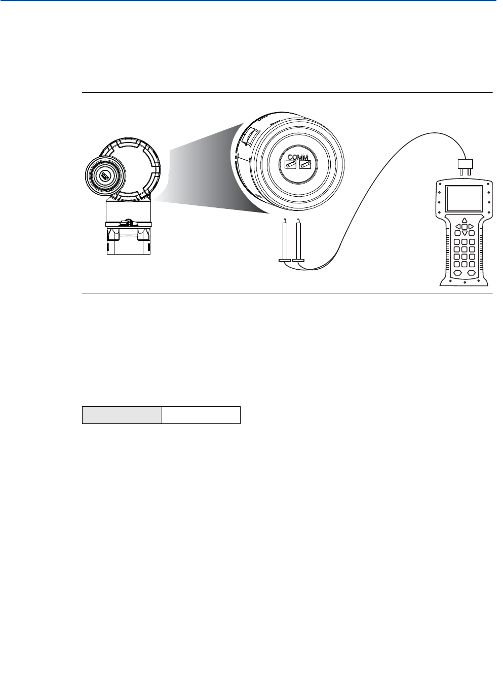
11
Reference Manual
00809-0100-4100, Rev AA
Section 2: Configuration
June 2012
Configuration
Field Hook-up
Figure 2-1 on page 11 illustrates the wiring for a field hook-up with a Field Communicator or
AMS. The Field Communicator or AMS may be connected at “COMM” on the transmitter
terminal block.
Figure 2-1. Field Communicator Connection
For HART communication, a 3051 WirelessHART DD is required.
2.4 Device Network Configuration
2.4.1 Join Device to Network
In order to communicate with the Smart Wireless Gateway, and ultimately the Host System, the
transmitter must be configured to communicate over the wireless network. This step is the
wireless equivalent of connecting wires from a transmitter to the host system.
1. From the Home screen, select 2: Configure.
2. Select 1: Guided Setup.
3. Select 1: Join Device to Network.
Using a Field Communicator or AMS, enter the Network ID and Join Key so that they match the
Network ID and Join Key of the Smart Wireless Gateway and other devices in the network. If the
Network ID and Join Key are not identical to those set in the Gateway, the transmitter will not
communicate with the network. The Network ID and Join Key may be obtained from the Smart
Wireless Gateway on the Setup>Network>Settings page on the web server.
Fast Keys 2, 1, 1

12
Reference Manual
00809-0100-4100, Rev AA
Section 2: Configuration
June 2012
Configuration
2.4.2 Configure Update Rate
The Update Rate is the frequency at which a new measurement is taken and transmitted over
the wireless network. This by default is 1 minute. This may be changed at commissioning, or at
any time via AMS Wireless Configurator. The Update Rate is user selectable from 8 seconds to 60
minutes.
1. From the Home screen, select 2: Configure.
2. Select 1: Guided Setup.
3. Select 2: Configure Update Rate.
When device configuration is completed, remove the Power Module and replace the housing
cover. Tighten the cover so that metal contacts metal.
2.4.3 Remove Power Module
After the sensor and network have been configured, remove the Power Module and replace the
housing cover. The Power Module should be inserted only when the device is ready to be
commissioned.
Use caution when handling the Power Module. The Power Module may be damaged if dropped
from heights in excess of 20 ft.
Fast Keys 2, 1, 2

13
Reference Manual
00809-0100-4100, Rev AA
Section 2: Configuration
June 2012
Configuration
2.5 Review Configuration Data
The following is a list of factory default configurations that can be viewed by using the Field
Communicator or AMS. Follow the steps below to review the transmitter configuration
information.
Note
Information and procedures in this section that make use of Field Communicator fast key
sequences and AMS assume that the transmitter and communication equipment are
connected, powered, and operating correctly.
2.5.1 Review Pressure Information
To view pressure information:
1. From the Home screen, select 2: Configure.
2. Select 2: Manual Setup.
3. Select 2: Pressure.
4. Select from the corresponding number to view each field:
2.5.2 Review Device Information
To view device information:
1. From the Home screen, select 2: Configure.
2. Select 2: Manual Setup.
3. Select 4: Device Information.
4. Select 3: Device.
5. Select from the corresponding number to view each field:
Fast Keys 2, 2, 2
1Unit
2Transfer Function
3Damping
4Upper Range Value
5Lower Range Value
6Maximum
7Minimum
8Minimum Span
Fast Keys 2, 2, 4, 3
1Manufacturer
2Model


15
Reference Manual
00809-0100-4100, Rev AA
Section 2: Configuration
June 2012
Configuration
2.5.3 Review Sensor Information
To view sensor information:
1. From the Home screen, select 2: Configure.
2. Select 2: Manual Setup.
3. Select 4: Device Information.
4. Select 4: Sensor.
5. Select from the corresponding number to view each field:
2.5.4 Review Radio Information
To view radio information:
1. From the Home screen, select 2: Configure.
2. Select 2: Manual Setup.
3. Select 4: Device Information.
4. Select 5: Radio.
5. Select from the corresponding number to view each field:
Fast Keys 2, 2, 4, 4
1Measurement Type
2Module Type
3Module Serial Number
4Sensor Materials
Isolator Material
Fill Fluid
5Process Connector
Connector Type
Connector Material
O Ring Material
Drain Vent Material
6Remote Seal
Number of Seals
Seal Type
Diaphragm Material
Seal Fill Fluid
Fast Keys 2, 2, 4, 5
1Manufacturer
2Device Type
3Device Revision
4Software Revision
5Hardware Revision

16
Reference Manual
00809-0100-4100, Rev AA
Section 2: Configuration
June 2012
Configuration
2.6 Field Communicator
1. Overview
2. Configure
3. Service Tools
1. Active Alerts
2. Communication Status
3. Pressure
4. Pressure Status
5. Last Update Time
1. Join Device to Network
2. Configure Update Rate
3. Zero Trim
4. Configure Device Display
5. Configure Process Alarms
6. Basic Setup
1. Guided Setup
2. Manual Setup
3. Alert Setup
1. Wireless
2. Pressure
3. Device Temperatures
4. Device Information
5. Device Display
6. Other
1. Network ID
2. Join Device to Network
3. Broadcast Rates
4. Configure Broadcast Power Level
5. Power Mode
6. Power Source 1. Unit
2. Transfer Function
3. Damping
4. Upper Range Value
5. Lower Range Value
6. Maximum
7. Minimum
8. Minimum Span
9. Range Using Applied Value
1. Sensor Temperature
2. Electronics Temperature
1. Unit
2. Maximum
3. Minimum
1. HI-HI Alarm
2. HI Alarm
3. LO Alarm
4. LO-LO Alarm
1. Configure LO-LO Alarm
2. Mode
3. Variable
4. Alarm Direction
5. Alarm Limit
6. Dead Band
1. Configure LO Alarm
2. Mode
3. Variable
4. Alarm Direction
5. Alarm Limit
6. Dead Band
1. Configure HI-HI Alarm
2. Mode
3. Variable
4. Alarm Direction
5. Alarm Limit
6. Dead Band
1. Configure HI Alarm
2. Mode
3. Variable
4. Alarm Direction
5. Alarm Limit
6. Dead Band
1. Mode
2. Display Options
1. Measurement and
Status Log
1. Alerts
2. Variables
3. Communications
4. Routine Maintenance
5. Simulate
1. Active Alerts
2. History
1. Percent of Range
2. Pressure
3. Pressure Status
4. Sensor Temperature
5. Sensor Temperature Status
6. Electronics Temperature
7. Electronics Temp Status
8. Supply Voltage
9. Supply Voltage Status
10. Last Update Time
1. Join Status
2. Communication Status
3. Join Mode
4. Number of Available
Neighbors
5. Number of Advertisements
Heard
6. Number of Join Attempts
1. Sensor Calibration
2. Other
1. Current Lower Trim
2. Current Upper Trim
3. Zero Sensor Trim
4. Lower Sensor Trim
5. Upper Sensor Trim
6. Recall Factory Trim
1. Master Reset
2. Measurement History
3. Advertise to New Devices
1. Pressure
2. Sensor Temperature
3. Electronics Temperature
4. Supply Voltage
1. Tag
2. Long Tag
3. Device
4. Sensor
5. Radio
6. Write Protect
1. Manufacturer
2. Model
3. Final Assembly Number
4. Universal
5. Field Device
6. Software
7. Hardware
8. Descriptor
9. Message
10. Date
11. Model Number I
12. Model Number II
13. Model Number III
14. SI Unit Restriction
15. Country
16. Device ID
1. Measurement Type
2. Module Type
3. Module Serial Number
4. Sensor Materials
5. Process Connector
6. Remote Seal
1. Isolator Fluid
2. Fill Fluid
1. Number of Seals
2. Seal Type
3. Diaphragm Material
4. Seal Fill Fluid
1. Connector Type
2. Connector Material
3. O Ring Material
4. Drain Vent Material
1. Manufacturer
2. Device Type
3. Device Revision
4. Software Revision
5. Hardware Revision
1. Configure Update Rate
2. Message 1
3. Message 2

17
Reference Manual
00809-0100-4100, Rev AA
Section 2: Configuration
June 2012
Configuration
2.7 Check Output
Before performing other transmitter operations, ensure that the transmitter is operating
properly by checking the operating parameters.
2.7.1 Operating Parameters
The pressure output value in both engineering units and percent of range will reflect the applied
pressure even when the applied pressure is outside of the configured range as long as the
applied pressure is between the upper and lower range limit of the transmitter. For example, if a
Range 2 3051T (LRL = 0 psi, URL = 150 psi) is ranged from 0 to 100 psi, an applied pressure of
150 psi will return a % of range output of 150% and an engineering output of 150 psi.
To view the Operating Parameters menu:
1. From the Home screen, select 3: Service Tools.
2. Select 2: Variables.
The Operating Parameters menu displays the following information pertaining to the device:
Percent of Range
Pressure
Pressure Status
Sensor Temperature
Sensor Temperature Status
Electronics Temperature
Electronics Temperature Status
Supply Voltage
Supply Voltage Status
Last Update Time
2.8 Basic Setup
2.8.1 Set Process Variable Unit
The PV Unit command sets the process variable units to allow you to monitor your process using
the appropriate units of measure.
To select a unit of measure for the PV:
Fast Keys 3, 2
Fast Keys 2, 2, 2, 1

18
Reference Manual
00809-0100-4100, Rev AA
Section 2: Configuration
June 2012
Configuration
1. From the Home screen, select 2: Configure.
2. Select 2: Manual Setup.
3. Select 2: Pressure.
4. Select 1: Unit to select from the following engineering units:
inH2Obar torr
inHg mbar atm
ftH2Og/cm2MPa
mmH2Okg/cm2inH2O at 4 °C
mmHg Pa mmH2O at 4 °C
psi kPa
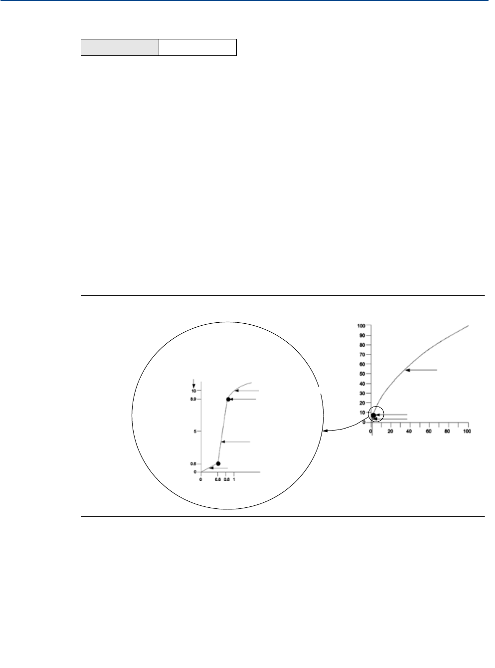
19
Reference Manual
00809-0100-4100, Rev AA
Section 2: Configuration
June 2012
Configuration
2.8.2 Set Transfer Function
The 3051 Wireless has two output settings: Linear and Square Root. Activate the square root
output option to make output proportional to flow. As input approaches zero, the 3051
Wireless automatically switches to linear output in order to ensure a more smooth, stable
output near zero (see Figure 2-2).
From 0 to 0.6 percent of the ranged pressure input, the slope of the curve is unity (y = x). This
allows accurate calibration near zero. Greater slopes would cause large changes in output (for
small changes at input). From 0.6 percent to 0.8 percent, curve slope equals 42 (y = 42x) to
achieve continuous transition from linear to square root at the transition point.
To select the output transfer function:
1. From the Home screen, select 2: Configure.
2. Select 2: Manual Setup.
3. Select 2: Pressure.
4. Select 2: Transfer Function and choose either Linear or Square Root.
Figure 2-2. Square Root Output Transition Point
Fast Keys 2, 2, 2, 2
Sq. Root
Curve
Transition Point
Linear Section
Slope=1
Slope=42
Transition Point
Sq. Root Curve
Full Scale
Flow (%)

20
Reference Manual
00809-0100-4100, Rev AA
Section 2: Configuration
June 2012
Configuration
2.8.3 Damping
The Damping command introduces a delay in processing which increases the response time of
the transmitter; smoothing variations in output readings caused by rapid input changes. In the
3051 Wireless pressure transmitter, damping only takes effect when the device is placed in high
power refresh mode and during calibration. In normal power mode, the effective damping is 0.
Note that when the device is in high power refresh mode, battery power will be depleted rapidly.
Determine the appropriate damp setting based on the necessary response time, signal stability,
and other requirements of the loop dynamics of your system. The damping value of your device
is user selectable from 0 to 25.6 seconds.
To determine the current damping value:
1. From the Home screen, select 2: Configure.
2. Select 2: Manual Setup.
3. Select 2: Pressure.
4. Select 3: Damping.
2.8.4 Write Protect
The 3051 Wireless has a software write protect security feature.
The view write protect security settings:
1. From the Home screen, select 2: Configure.
2. Select 2: Manual Setup.
3. Select 4: Device Information.
4. Select 6: Write Protect.
Fast Keys 2, 2, 2, 3
Fast Keys 2, 2, 4, 6

21
Reference Manual
00809-0100-4100, Rev AA
Section 2: Configuration
June 2012
Configuration
2.9 LCD Display
2.9.1 LCD Display Configuration
The LCD display indicates output and abbreviated diagnostic messages.
Note
Use Rosemount Wireless LCD Part Number: 00753-9004-0002.
The LCD display features a four-line display and a bar graph. The first line of five characters
displays the output description, the second line of seven digits displays the actual value, the
third line of six characters displays engineering units and the fourth line displays “Error” when
the transmitter is in alarm. The LCD display can also display diagnostic messages. The bar graph
represents the network connectivity status.
See “LCD Screen Messages” on page 57 for more information on LCD messages.
To configure LCD display options:
1. From the Home screen, select 2: Configure.
2. Select 1: Guided Setup.
3. Select 4: Configure Device Display.
Fast Keys 2, 1, 4
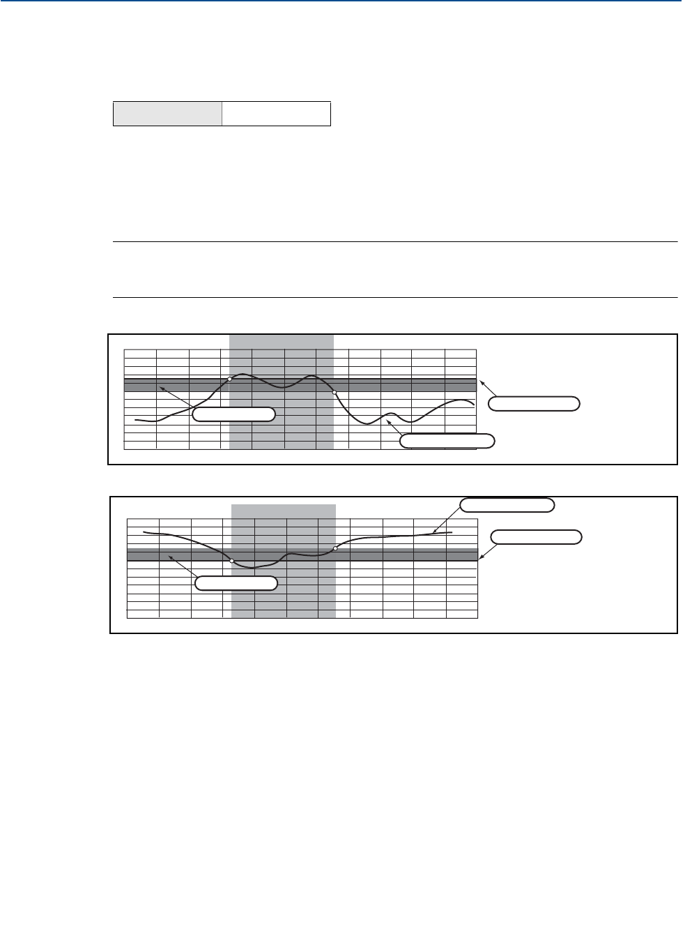
22
Reference Manual
00809-0100-4100, Rev AA
Section 2: Configuration
June 2012
Configuration
2.10 Detailed Setup
2.10.1 Configure Process Alarms
Alerts allow the user to configure the transmitter to output a HART message when the
configured data point is exceeded. A process alert will be transmitted continuously if the set
points are exceeded and the alert mode is ON. An alert will be displayed on a Field
Communicator, AMS status screen or in the error section of the LCD display. The alert will reset
once the value returns within range.
Note
HI alert value must be higher than the LO alert value. Both alert values must be within the
pressure or temperature sensor limits.
Example 1: Rising Alert
Example 2: Falling Alert
To configure the process alerts, perform the following procedure:
1. From the Home screen, select 2: Configure.
2. Select 1: Guided Setup.
3. Select 5: Configure Process Alarms and follow the on-screen instructions to complete
configure of process alarms.
Fast Keys 2, 1, 5
Deadband
Assigned Value
Alert Set Point
Alert “OFF” Alert “ON” Alert “OFF”
Units of Measurement
Time
Deadband
Assigned Value
Alert Set Point
Alert “OFF” Alert “ON” Alert “OFF”
Units of Measurement
Time

23
Reference Manual
00809-0100-4100, Rev AA
Section 2: Configuration
June 2012
Configuration
2.10.2 Sensor Temperature Unit
The Sensor Temperature Unit command selects between Celsius and Fahrenheit units for the
sensor temperature. The sensor temperature output is accessible via HART only.
To select the sensor temperature unit:
1. From the Home screen, select 2: Configure.
2. Select 2: Manual Setup.
3. Select 3: Device Temperatures.
4. Select 1: Sensor Temperature.
5. Select 1: Unit to select from Celsius or Fahrenheit.
2.11 Diagnostics and Service
Diagnostics and service functions listed below are primarily for use after field installation. The
Transmitter Test feature is designed to verify that the transmitter is operating properly, and can
be performed either on the bench or in the field.
2.11.1 Master Reset
The master reset function will reset the device electronics. To perform a master reset:
1. From the Home screen, select 3: Service Tools.
2. Select 4: Routine Maintenance.
3. Select 2: Other.
4. Select 1: Master Reset.
2.11.2 Join Status
To view the join status of the device, perform the following procedure:
1. From the Home screen, select 3: Service Tools.
2. Select 3: Communications.
3. Select 1: Join Status.
Fast Keys 2, 2, 3, 1, 1
Fast Keys 3, 4, 2, 1
Fast Keys 3, 3, 1

24
Reference Manual
00809-0100-4100, Rev AA
Section 2: Configuration
June 2012
Configuration
Wireless devices join the secure network through a four step process:
Step 1. Network Found
Step 2. Network Security Clearance Granted
Step 3. Network Bandwidth Allocated
Step 4. Network Join Complete
2.11.3 Number of Available Neighbors
In a self-organizing network, the more neighbors a device has, the more robust the network will
be. To view the number of available neighbors for the wireless device, perform the following
procedure:
1. From the Home screen, select 3: Service Tools.
2. Select 3: Routine Maintenance.
3. Select 4: Number of Available Neighbors.
Fast Keys 3, 3, 4

25
Reference Manual
00809-0100-4100, Rev AA
Section 2: Configuration
June 2012
Configuration
2.12 Advanced Functions for HART Protocol
2.12.1 Saving, Recalling, and Cloning Configuration Data
Use the cloning feature of the Field Communicator or the AMS “User Configuration” feature to
configure several 3051 Wireless transmitters similarly. Cloning involves configuring a
transmitter, saving the configuration data, then sending a copy of the data to a separate
transmitter. Several possible procedures exist when saving, recalling, and cloning configuration
data. For complete instructions refer to the Field Communicator manual (publication no.
00809-0100-4276) or AMS Books Online. One common method is as follows:
Field Communicator
1. Completely configure the first transmitter.
2. Save the configuration data:
a. Select F2 SAVE from the Field Communicator HOME/ONLINE screen.
b. Ensure that the location to which the data will be saved is set to MODULE. If it is not,
select 1: Location to set the save location to MODULE.
c. Select 2: Name, to name the configuration data. The default is the transmitter tag
number.
d. Ensure that the data type is set to STANDARD. If the data type is NOT STANDARD,
select 3: Data Type to set the data type to STANDARD.
e. Select F2 SAVE.
3. Connect and power the receiving transmitter and Field Communicator.
4. Select the back arrow from the HOME/ONLINE screen. The Field Communicator menu
appears.
5. Select 1: Offline, 2: Saved Configuration, 1: Module Contents to reach the MODULE
CONTENTS menu.
6. Use the DOWN ARROW to scroll through the list of configurations in the memory
module, and use the RIGHT ARROW to select and retrieve the required configuration.
7. Select 1: Edit.
8. Select 1: Mark All.
9. Select F2 SAVE.
10. Use the DOWN ARROW to scroll through the list of configurations in the memory
module, and use the RIGHT ARROW to select the configuration again.
11. Select 3: Send to download the configuration to the transmitter.
12. Select OK after the control loop is set to manual.
13. After the configuration has been sent, select OK.
Fast Keys left arrow, 1, 2

26
Reference Manual
00809-0100-4100, Rev AA
Section 2: Configuration
June 2012
Configuration
When finished, the Field Communicator informs you of the status. Repeat Steps 3 through 13 to
configure another transmitter.
Note
The transmitter receiving cloned data must have the same software version (or later) as the
original transmitter.
AMS creating a Reusable Copy
To create a reusable copy of a configuration perform the following procedure:
1. Completely configure the first transmitter.
2. Select View then User Configuration View from the menu bar (or click the toolbar
button).
3. In the User Configuration window, right click and select New from the context menu.
4. In the New window, select a device from the list of templates shown, and click OK.
5. The template is copied into the User Configurations window, with the tag name
highlighted; rename it as appropriate and press Enter.
Note
A device icon can also be copied by dragging and dropping a device template or any other
device icon from AMS Explorer or Device Connection View into the User Configurations window.
The “Compare Configurations” window appears, showing the Current values of the copied
device on one side and mostly blank fields on the other (User Configuration) side.
6. Transfer values from the current configuration to the user configuration as appropriate
or enter values by typing them into the available fields.
7. Click Apply to apply the values, or click OK to apply the values and close the window.
AMS Applying a User Configuration
Any amount of user configurations can be created for the application. They can also be saved,
and applied to connected devices or to devices in the Device List or Plant Database.
To apply a user configuration perform the following procedure:
1. Select the desired user configuration in the User Configurations window.
2. Drag the icon onto a like device in AMS Explorer or Device Connection View. The
Compare Configurations window opens, showing the parameters of the target device
on one side and the parameters of the user configuration on the other.
3. Transfer parameters from the user configuration to the target device as desired, Click
OK to apply the configuration and close the window.

Reference Manual
00809-0100-4100, Rev AA
Section 3: Installation
June 2012
27
Installation
Section 3 Installation
Overview . . . . . . . . . . . . . . . . . . . . . . . . . . . . . . . . . . . . . . . . . . . . . . . . . . . . . . . . . . . . . . . page 27
Safety Messages . . . . . . . . . . . . . . . . . . . . . . . . . . . . . . . . . . . . . . . . . . . . . . . . . . . . . . . . . page 27
Considerations . . . . . . . . . . . . . . . . . . . . . . . . . . . . . . . . . . . . . . . . . . . . . . . . . . . . . . . . . . page 29
Installation Procedures . . . . . . . . . . . . . . . . . . . . . . . . . . . . . . . . . . . . . . . . . . . . . . . . . . . page 31
Installing the LCD Display . . . . . . . . . . . . . . . . . . . . . . . . . . . . . . . . . . . . . . . . . . . . . . . . . page 37
Rosemount 304, 305 and 306 Integral Manifolds . . . . . . . . . . . . . . . . . . . . . . . . . . . . page 38
3.1 Overview
The information in this section covers installation considerations. A Quick Installation Guide
(document number 00825-0100-4100) is shipped with every transmitter to describe basic
installation and startup procedures. Dimensional drawings for each Rosemount 3051 Wireless
variation and mounting configuration are included in Appendix A: Specifications and Reference
Data.
Field Communicator and AMS instructions are given to perform configuration functions. For
convenience, Field Communicator fast key sequences are labeled “Fast Keys” for each software
function below the appropriate headings.
3.2 Safety Messages
Procedures and instructions in this section may require special precautions to ensure the safety
of the personnel performing the operation. Information that raises potential safety issues is
indicated with a warning symbol ( ). Refer to the following safety messages before
performing an operation preceded by this symbol.

28
Reference Manual
00809-0100-4100, Rev AA
Section 3: Installation
June 2012
Installation
3.2.1 Warnings ( )
Failure to follow these installation guidelines could result in death or serious injury.
Make sure only qualified personnel perform the installation.
Explosions can result in death or serious injury.
Installation of this transmitter in an explosive environment must be in accordance with the
appropriate local, national, and international standards, codes, and practices. Please review
the approvals section of the 3051 Wireless reference manual for any restrictions associated
with a safe installation.
Before connecting a Field Communicator in an explosive atmosphere, make sure the
instruments are installed in accordance with intrinsically safe or non-incendive field
wiring practices.
Verify that the operating atmosphere of the transmitter is consistent with the
appropriate hazardous locations certifications.
Electrical shock can result in death or serious injury.
Avoid contact with the leads and terminals. High voltage may be present on leads can
cause electrical shock.
Process leaks could result in death or serious injury.
Install and tighten process connectors before applying pressure.
Do not attempt to loosen or remove process connectors while the transmitter is
in service.
Replacement equipment or spare parts not approved by Rosemount Inc. for use as spare
parts could reduce the pressure retaining capabilities of the transmitter and may render the
instrument dangerous.
Use only bolts supplied or sold by Rosemount Inc. as spare parts.
Improper assembly of manifolds to traditional flange can damage SuperModule™.
For safe assembly of manifold to traditional flange, bolts must break back plane of
flange web (i.e., bolt hold) but must not contact module housing.
The Power Module with the wireless unit contains one “D” size primary lithium/thionyl
chloride battery (Green Power Module, model number 701PGNKF). Each Power Module
contains approximately 5 grams of lithium. Under normal conditions, the Power Module
materials are self-contained and are not reactive as long as the batteries and the pack
integrity are maintained. Care should be taken to prevent thermal, electrical or mechanical
damage. Contacts should be protected to prevent premature discharge.

29
Reference Manual
00809-0100-4100, Rev AA
Section 3: Installation
June 2012
Installation
3.3 Considerations
3.3.1 General
Measurement performance depends upon proper installation of the transmitter and impulse
piping. Mount the transmitter close to the process and use a minimum of piping to achieve best
performance. Also, consider the need for easy access, personnel safety, practical field
calibration, and a suitable transmitter environment. Install the transmitter to minimize
vibration, shock, and temperature fluctuation.
3.3.2 Wireless
Power Up Sequence
The Power Module should not be installed on any wireless device until the Smart Wireless
Gateway is installed and functioning properly. Wireless devices should also be powered up in
order of proximity from the Smart Wireless Gateway beginning with the closest. This will result
in a simpler and faster network installation. Enable High Speed Operation on the Gateway to
ensure that new devices join the network faster. For more information see the Smart Wireless
Gateway Manual (Doc. No. 00809-0200-4420).
Field Communicator Connections
In order for the Field Communicator to interface with the 3051, the Power Module must be
connected.
Figure 3-1. Field Communicator Connections
3.3.3 Mechanical
Note
For steam service or for applications with process temperatures greater than the limits of the
transmitter, do not blow down impulse piping through the transmitter. Flush lines with the
blocking valves closed and refill lines with water before resuming measurement.
Note
When the transmitter is mounted on its side, position the Coplanar flange to ensure proper
venting or draining. Mount the flange as shown in Figure 3.4.2 on page 34, keeping drain/vent
connections on the bottom for gas service and on the top for liquid service.

30
Reference Manual
00809-0100-4100, Rev AA
Section 3: Installation
June 2012
Installation
3.3.4 Environmental
Access requirements and cover installation on page 31 can help optimize transmitter
performance. Mount the transmitter to minimize ambient temperature changes, vibration,
mechanical shock, and to avoid external contact with corrosive materials. Appendix A:
Specifications and Reference Data lists temperature operating limits.
Figure 3-2. Installation Flowchart
START HERE
Bench
Calibration? Field Install
No
Configure
(Section 2)
Set Units
Set Range
Points
Set Network
Parameters
Verify
Apply Pressure
Yes
Within
Specifications? Yes
No
Refer to
Section 4
Operation and
Maintenance
Check Switches
(page 36)
Mount
Transmitter
(page 31)
Install Power
Module
(pages 37–36)
Check Process
Connection
(page 34)
Trim Transmitter
for Mounting
Effects
(page 52)
Done
Review
Transmitter
Configuration
(page 11)
Confirm
Transmitter
Configuration
(page 11)

31
Reference Manual
00809-0100-4100, Rev AA
Section 3: Installation
June 2012
Installation
3.4 Installation Procedures
For dimensional drawing information refer to “Dimensional Drawings” on page 93.
Process Flange Orientation
Mount the process flanges with sufficient clearance for process connections. For safety reasons,
place the drain/vent valves so the process fluid is directed away from possible human contact
when the vents are used. In addition, consider the need for a testing or calibration input.
Housing Rotation
See “Consider Housing Rotation” on page 36.
Power Module Side of Electronics Housing
Mount the transmitter so the Power Module side is accessible. Clearance of 2.75-in. (70 mm) is
required for cover removal.
Circuit Side of Electronics Housing
Provide 0.75 in. (19 mm) of clearance for units with out an LCD display. Three inches of
clearance is required for cover removal if a meter is installed.
Cover Installation
Always ensure a proper seal by installing the electronics housing cover(s) so that polymer
contacts polymer. Use Rosemount O-rings.
3.4.1 Mount the Transmitter
Mounting Brackets
Facilitate mounting transmitter to a 2-in. pipe, or to a panel. The B4 Bracket (SST) option is
standard for use with the Coplanar and In-Line flanges. “Coplanar Flange Mounting Configura-
tions” on page 93 shows bracket dimensions and mounting configurations for the B4 option.
Options B1–B3 and B7–B9 are sturdy, epoxy/polyester-painted brackets designed for use with
the traditional flange. The B1–B3 brackets have carbon steel bolts, while the B7–B9 brackets
have stainless steel bolts. The BA and BC brackets and bolts are stainless steel. The B1/B7/BA
and B3/B9/BC style brackets support 2-inch pipe-mount installations, and the B2/B8 style
brackets support panel mounting.
Note
Most transmitters are calibrated in the horizontal position. Mounting the transmitter in any
other position will shift the zero point to the equivalent amount of liquid head caused by the
varied mounting position. To reset zero point, refer to “Sensor Trim” on page 53.
Position the antenna such that it is vertical, typically straight up (antenna may be pointed down
as well.)
32
Reference Manual
00809-0100-4100, Rev AA
Section 3: Installation
June 2012
Installation
Flange Bolts
The 3051 can be shipped with a Coplanar flange or a Traditional flange installed with four
1.75-inch flange bolts. Mounting bolts and bolting configurations for the Coplanar and
Traditional flanges can be found on page 2-6, 7. Stainless steel bolts supplied by Emerson
Process Management are coated with a lubricant to ease installation. Carbon steel bolts do not
require lubrication. No additional lubricant should be applied when installing either type of bolt.
Bolts supplied by Emerson Process Management are identified by their head markings:
Bolt Installation
Only use bolts supplied with the Rosemount 3051 or sold by Emerson Process Management as
spare parts. When installing the transmitter to one of the optional mounting brackets, torque
the bolts to 125 in-lb. (0,9 N-m). Use the following bolt installation procedure:
1. Finger-tighten the bolts.
2. Torque the bolts to the initial torque value using a crossing pattern.
3. Torque the bolts to the final torque value using the same crossing pattern.
Torque values for the flange and manifold adapter bolts are as follows:
Table 3-1. Bolt Installation
Torque Values
Bolt Material Initial Torque Value Final Torque Value
CS-ASTM-A445 Standard 300 in.-lb (34 N-m) 650 in.-lb (73 N-m)
316 SST—Option L4 150 in.-lb (17 N-m) 300 in.-lb (34 N-m)
ASTM-A-193-B7M—Option L5 300 in.-lb (34 N-m) 650 in.-lb (73 N-m)
Alloy K-500—Option L6 300 in.-lb (34 N-m) 650 in.-lb (73 N-m)
ASTM-A-453-660—Option L7 150 in.-lb (17 N-m) 300 in.-lb (34 N-m)
ASTM-A-193-B8M—Option L8 150 in.-lb (17 N-m) 300 in.-lb (34 N-m)
Carbon Steel (CS) Head Markings
B7M
316 B8M F593_
Stainless Steel (SST) Head Markings
* The last digit in the F593_ head marking may
be any letter between A and M.
F593_
KM
660
CL A
Alloy K-500 Head Marking

33
Reference Manual
00809-0100-4100, Rev AA
Section 3: Installation
June 2012
Installation
Impulse Piping
The piping between the process and the transmitter must accurately transfer the pressure to
obtain accurate measurements. There are five possible sources of error: leaks, friction loss
(particularly if purging is used), trapped gas in a liquid line, liquid in a gas line, and density
variations between the legs.
The best location for the transmitter in relation to the process pipe depends on the process
itself. Use the following guidelines to determine transmitter location and placement of impulse
piping:
Keep impulse piping as short as possible.
For liquid service, slope the impulse piping at least 1 inch per foot (8 cm per m) upward
from the transmitter toward the process connection.
For gas service, slope the impulse piping at least 1 inch per foot (8 cm per m) downward
from the transmitter toward the process connection.
Avoid high points in liquid lines and low points in gas lines.
Make sure both impulse legs are the same temperature.
Use impulse piping large enough to avoid friction effects and blockage.
Vent all gas from liquid piping legs.
When using a sealing fluid, fill both piping legs to the same level.
When purging, make the purge connection close to the process taps and purge
through equal lengths of the same size pipe. Avoid purging through the transmitter.
Keep corrosive or hot (above 250 °F [121 °C]) process material out of direct contact
with the SuperModule and flanges.
Prevent sediment deposits in the impulse piping.
Keep the liquid head balanced on both legs of the impulse piping.
Avoid conditions that might allow process fluid to freeze within the process flange.

34
Reference Manual
00809-0100-4100, Rev AA
Section 3: Installation
June 2012
Installation
Mounting Requirements
Refer to Figure 3.4.2 for examples of the following mounting configurations:
Liquid Flow Measurement
Place taps to the side of the line to prevent sediment deposits on the process isolators.
Mount the transmitter beside or below the taps so gases vent into the process line.
Mount drain/vent valve upward to allow gases to vent.
Gas Flow Measurement
Place taps in the top or side of the line.
Mount the transmitter beside or above the taps so to drain liquid into the process line.
Steam Flow Measurement
Place taps to the side of the line.
Mount the transmitter below the taps to ensure that impulse piping will remain filled
with condensate.
Fill impulse lines with water to prevent steam from contacting the transmitter directly
and to ensure accurate measurement start-up.
Note
For steam or other elevated temperature services, it is important that temperatures at the
Coplanar process flanges must not exceed 250 °F (121 °C) for transmitters with silicone fill, or
185 °F (85 °C) for inert fill. For vacuum service, these temperature limits are reduced to 220 °F
(104 °C) for silicone fill and 160 °F (71 °C) for inert fill.
3.4.2 Process Connections
3051 Wireless transmitter flange process connection size is 1/4–18 NPT. Flange adapters with
1/2–14 NPT connections are available as the D2 option. Use your plant-approved lubricant or
sealant when making the process connections. The process connections on the transmitter
flange are on 21/8-inch (54 mm) centers to allow direct mounting to a three-valve or five-valve
manifold. Rotate one or both of the flange adapters to attain connection centers of 2 inches
(51 mm), 21/8inches (54 mm), or 21/4inches (57 mm).
Install and tighten all four flange bolts before applying pressure to avoid leakage. When properly
installed, the flange bolts will protrude through the top of the sensor module housing. Do not
attempt to loosen or remove the flange bolts while the transmitter is in service.
To install adapters to a Coplanar flange, perform the following procedure:
1. Remove the flange bolts.
2. Leaving the flange in place, move the adapters into position with the O-ring installed.
3. Clamp the adapters and the Coplanar flange to the transmitter module using the longer
of the bolts supplied.
4. Tighten the bolts. Refer to “Flange Bolts” on page 32 for torque specifications.
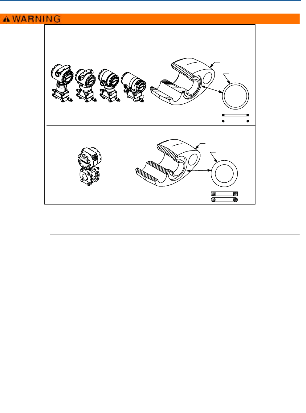
35
Reference Manual
00809-0100-4100, Rev AA
Section 3: Installation
June 2012
Installation
Note
PTFE O-rings should be replaced if the flange adapter is removed.
Whenever you remove flanges or adapters, visually inspect the Teflon® O-rings. Replace them if
there are any signs of damage, such as nicks or cuts. If you replace the O-rings, re-torque the
flange bolts after installation to compensate for cold flow. Refer to the process sensor body
reassembly procedure in Section 6: Troubleshooting on page 67.
Failure to install proper flange adapter o-rings may cause process leaks, which can result in death or
serious injury. The two flange adapters are distinguished by unique o-ring grooves. Only use the
o-ring that is designed for its specific flange adapter, as shown below.
ROSEMOUNT 3051S / 3051 / 2051 / 3001 / 3095 / 2024
ROSEMOUNT 1151
Flange Adapter
O-ring
Flange Adapter
O-ring
PTFE Based
Elastomer
PTFE
Elastomer
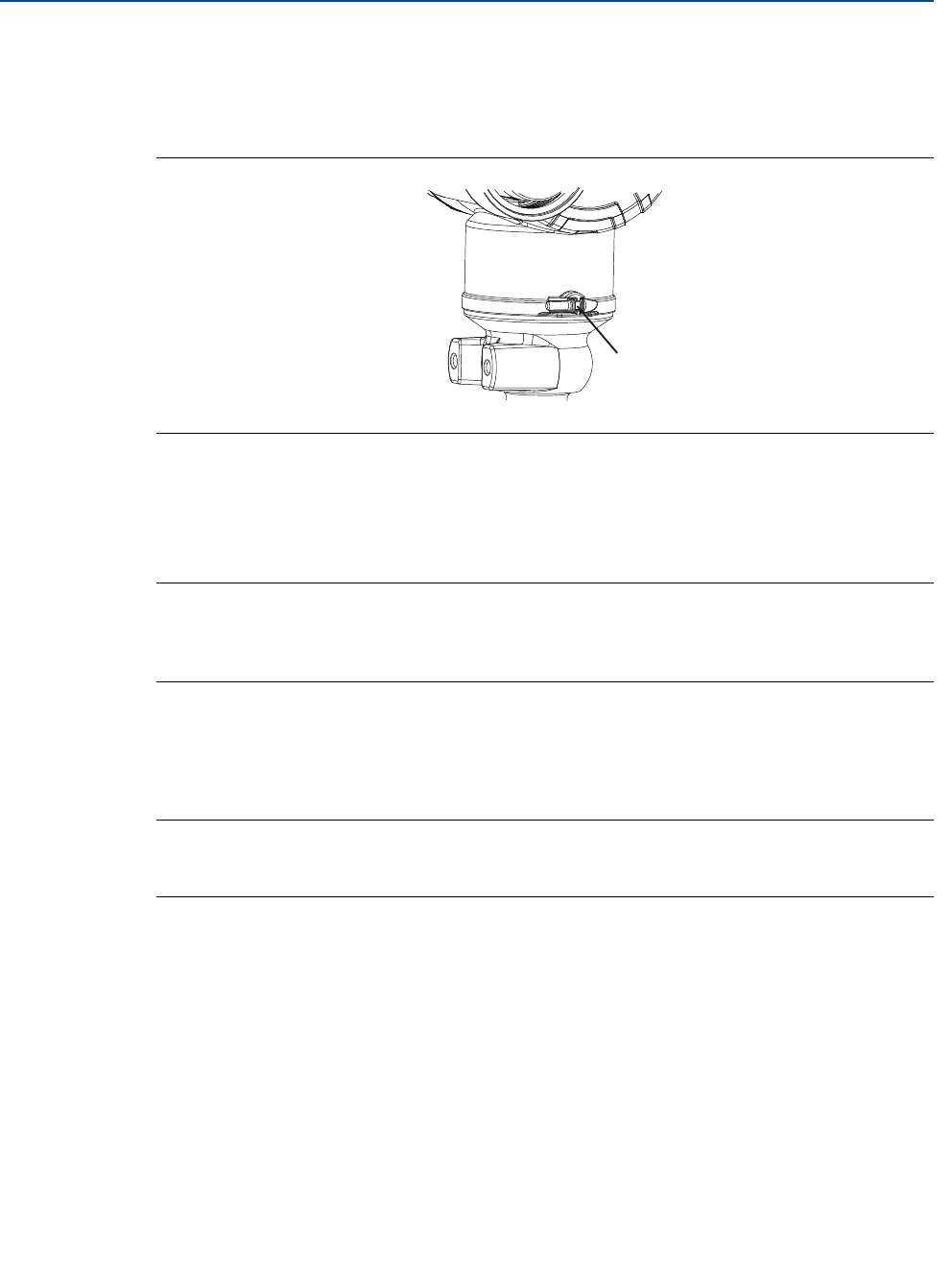
36
Reference Manual
00809-0100-4100, Rev AA
Section 3: Installation
June 2012
Installation
3.4.3 Consider Housing Rotation
The housing can be rotated to improve field access to wiring or to better view the optional LCD
display. Perform the following procedure:
Figure 3-3. Housing rotation
A. Housing rotation screw (5/64-inch hex wrench required)
1. Loosen the housing rotation set screw.
2. Turn the housing up to 180 degrees to the left or right of its original (as shipped)
position.
Note
Do not rotate the housing more than 180 degrees without first performing a disassembly
procedure (see “Removing from Service” on page 72). Over-rotation may sever the electrical
connection between the sensor module and the feature board.
3. Retighten the housing rotation set screw.
In addition to housing rotation, the optional LCD display can be rotated in 90-degree increments
by squeezing the two tabs, pulling out, rotating and snapping back into place.
Note
If LCD pins are inadvertently removed from the interface board, carefully re-insert the pins
before snapping the LCD display back into place.
3.4.4 Grounding
Transmitter Case
Always ground the transmitter case in accordance with national and local electrical codes. The
most effective transmitter case grounding method is a direct connection to earth ground with
minimal impedance. Methods for grounding the transmitter case include:
External Ground Assembly: This assembly is included with the optional transient
protection terminal block (Option Code T1), and it is included with various hazardous
location certifications. The External Ground Assembly can also be ordered with the
transmitter (Option Code V5), or as a spare part.
A
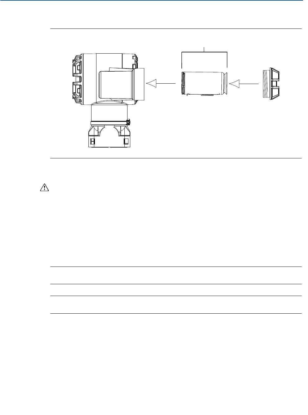
37
Reference Manual
00809-0100-4100, Rev AA
Section 3: Installation
June 2012
Installation
3.4.5 Power Module Installation
Figure 3-4. Power Module
A. Housing rotation screw (5/64-inch hex wrench required)
To make connections, perform the following procedure:
1. Remove the housing cover on the Power Module compartment side. The Power Module
supplies all power to the transmitter.
2. Connect Power Module 701PGNKF.
3. Replace the Power Module cover and tighten to safety specification (metal to metal).
3.4.6 Installing the LCD Display
Transmitters ordered with the LCD display will be shipped with the display installed.
Note
Only use Rosemount Wireless LCD Part Number: 00753-9004-0002
Note
An LCD from a wired device will not function in a wireless device.
In addition to housing rotation, the optional LCD display can be rotated in 90-degree increments
by squeezing the two tabs, pulling out, rotating and snapping back into place.
If LCD pins are inadvertently removed from the interface board, carefully re-insert the pins
before snapping the LCD display back into place.
Use the following procedure and Figure 3-5 to install the LCD display:
A
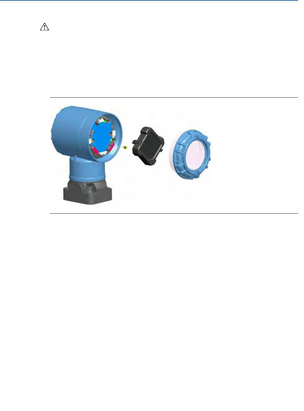
38
Reference Manual
00809-0100-4100, Rev AA
Section 3: Installation
June 2012
Installation
1. Remove the back cover and Power Module.
2. Remove the transmitter cover opposite the field terminal side. Do not remove the
instrument covers in explosive environments when the circuit is live.
3. Engage the four-pin connector into the LCD display and snap into place.
Note the following LCD temperature limits:
Operating:–40 to 175 °F (–40 to 80 °C)
Storage:–40 to 185 °F (–40 to 85 °C)
Figure 3-5. Optional LCD Display
3.5 Rosemount 304, 305 and 306 Integral Manifolds
The Rosemount 305 is available in two designs: Traditional and Coplanar. The traditional 305
Integral Manifold can be mounted to most primary elements with mounting adapters in the
market today. The Rosemount 306 Integral Manifold is used with In-line transmitters to provide
block-and-bleed valve capabilities of up to 10000 psi (690 bar). The Rosemount 304 comes in
two basic styles: traditional (flange x flange and flange x pipe) and wafer. The 304 traditional
manifold comes in 2, 3, and 5-valve configurations. The 304 wafer manifold comes in 3 and 5
valve configurations.

39
Reference Manual
00809-0100-4100, Rev AA
Section 3: Installation
June 2012
Installation
Figure 3-6. Integral Manifold Designs
3.5.1 Rosemount 305 Integral Manifold Installation Procedure
To install a 305 Integral Manifold to a 3051 Wireless transmitter:
1. Inspect the Teflon sensor module O-rings. If the O-rings are undamaged, reusing them
is recommended. If the O-rings are damaged (if they have nicks or cuts, for example),
replace them with new O-rings.
Important
If replacing the O-rings, take care not to scratch or deface the O-ring grooves or the surface of
the isolating diaphragm while you remove the damaged O-rings.
2. Install the Integral Manifold on the sensor module. Use the four 2.25-in. manifold bolts
for alignment. Finger tighten the bolts, then tighten the bolts incrementally in a cross
pattern to final torque value. See “Flange Bolts” on page 32 for complete bolt
installation information and torque values. When fully tightened, the bolts should
extend through the top of the module housing.
3. If the Teflon sensor module O-rings have been replaced, the flange bolts should be
re-tightened after installation to compensate for cold flow of the O-rings.
4. If applicable, install flange adapters on the process end of the manifold using the
1.75-in. flange bolts supplied with the transmitter.
Note
Always perform a zero trim on the transmitter/manifold assembly after installation to eliminate
mounting effects. See Section 5: Operation and Maintenance, “Zero Trim” on page 53.
3.5.2 Rosemount 306 Integral Manifold Installation Procedure
The 306 Manifold is for use only with a 3051T Wireless In-line transmitter.
Assemble the 306 Manifold to the 3051T Wireless In-line transmitter with a thread sealant.

40
Reference Manual
00809-0100-4100, Rev AA
Section 3: Installation
June 2012
Installation
1. Place transmitter into holding fixture.
2. Apply appropriate thread paste or tape to threaded instrument end of the manifold.
3. Count total threads on the manifold before starting assembly.
4. Start turning the manifold by hand into the process connection on the transmitter.
Note
If using thread tape, be sure the thread tape does no strip when the manifold assembly is
started.
5. Wrench tighten manifold into process connection. (Note: Minimum toque value is 425
in-lbs)
6. Count how many threads are still showing. (Note: Minimum engagement is 3
revolutions)
7. Subtract the number of threads showing (after tightening) from the total threads to
calculate the revolutions engaged. Further tighten until a minimum of 3 rotations is
achieved.
8. For block and bleed manifold, verify the bleed screw is installed and tightened. For
two-valve manifold, verify the vent plug is installed and tightened.
9. Leak-check assembly to maximum pressure range of transmitter.
3.5.3 Rosemount 304 Conventional Manifold Installation
Procedure
To install a 304 Conventional Manifold to a 3051 Wireless transmitter:
1. Align the Conventional Manifold with the transmitter flange. Use the four manifold
bolts for alignment.
2. Finger tighten the bolts, then tighten the bolts incrementally in a cross pattern to final
torque value. See “Flange Bolts” on page 2-6 for complete bolt installation information
and torque values. When fully tightened, the bolts should extend through the top of
the module housing.
3. If applicable, install flange adapters on the process end of the manifold using the
1.75-in. flange bolts supplied with the transmitter.
3.5.4 Manifold Operation
Improper installation or operation of manifolds may result in process leaks, which may cause
death or serious injury.
Always perform a zero trim on the transmitter/manifold assembly after installation to eliminate
any shift due to mounting effects. See Section 5: Operation and Maintenance, “Sensor Trim
Overview” on page 52.
Three and five-valve configurations shown:
41
Reference Manual
00809-0100-4100, Rev AA
Section 3: Installation
June 2012
Installation
Drain/
Vent
Valve
Drain/
Vent
Valve Equalize
(closed)
Process
Isolate
(open)
Isolate
(open)
HL
In normal operation the two block
valves between the process and
instrument ports will be open and the
equalizing valve will be closed.
Drain/
Vent
Valve Equalize
(closed)
Process
Isolate
(closed)
Isolate
(open)
HL
1. To zero the 3051, close the
block valve to the low
pressure (downstream) side
of the transmitter first.
Drain/
Vent
Valve
Drain/
Vent
Valve
Drain/
Vent
Valve Equalize
(open)
Process
Isolate
(closed)
Isolate
(open)
HL
2. Open the center (equalize)
valve to equalize the pressure
on both sides of the
transmitter. The manifold
valves are now in the proper
configuration for zeroing the
transmitter.
Drain/
Vent
Valve
Drain/
Vent
Valve Equalize
(closed)
Process
Isolate
(closed)
Isolate
(open)
HL
3. After zeroing the transmitter,
close the equalizing valve.
Drain/
Vent
Valve
Drain/
Vent
Valve Equalize
(closed)
Process
Isolate
(open)
Isolate
(open)
HL
4. Open the block valve on the
low pressure side of the
transmitter to return the
transmitter to service.
42
Reference Manual
00809-0100-4100, Rev AA
Section 3: Installation
June 2012
Installation
Five-valve Natural Gas configurations shown:
Note
Do not open the low side equalize valve before the high side equalize valve. Doing so will
overpressure the transmitter.
Test
(Plugged)
Test
(Plugged)
Equalize
(closed)
Process
Isolate
(open)
Isolate
(open)
HL
In normal operation, the two block
valves between the process and
instrument ports will be open, and the
equalizing valves will be closed.
Process
Equalize
(closed)
Drain
Vent
Test
(Plugged)
Test
(Plugged)
Equalize
(closed)
Process
Isolate
(closed)
Isolate
(open)
HL
1. To zero the 3051, first close
the block valve on the low
pressure (downstream) side
of the transmitter.
Process
Equalize
(closed)
Drain
Vent
Test
(Plugged)
Test
(Plugged)
Equalize
(closed)
Process
Isolate
(closed)
Isolate
(open)
HL
2. Open the equalize valve on
the high pressure (upstream)
side of the transmitter.
Process
Equalize
(open)
Drain Vent
(closed)
43
Reference Manual
00809-0100-4100, Rev AA
Section 3: Installation
June 2012
Installation
3. Open the equalize valve on
the low pressure
(downstream) side of the
transmitter. The manifold is
now in the proper
configuration for zeroing the
transmitter.
Test
(Plugged)
Test
(Plugged)
Equalize
(open)
Process
Isolate
(closed)
Isolate
(open)
HL
Process
Equalize
(open)
Drain Vent
(closed)
Test
(Plugged)
Test
(Plugged)
Equalize
(closed)
Process
Isolate
(closed)
Isolate
(open)
HL
4. After zeroing the transmitter,
close the equalize valve on
the low pressure
(downstream) side of the
transmitter.
Process
Equalize
(open)
Drain Vent
(closed)
5. Close the equalize valve on
the high pressure (upstream)
side.
Test
(Plugged)
Test
(Plugged)
Equalize
(closed)
Process
Isolate
(closed)
Isolate
(open)
HL
Process
Equalize
(closed)
Drain Vent
(closed)
6. Finally, to return the
transmitter to service, open
the low side isolation valve.
Test
(Plugged)
Test
(Plugged)
Equalize
(closed)
Process
Isolate
(open)
Isolate
(open)
HL
Process
Equalize
(closed)
Drain Vent
(closed)


Reference Manual
00809-0100-4100, Rev AA
Section 4: Commissioning
June 2012
47
Commissioning
Section 4 Commissioning
Safety Messages . . . . . . . . . . . . . . . . . . . . . . . . . . . . . . . . . . . . . . . . . . . . . . . . . . . . . . . . . page 47
Network Status . . . . . . . . . . . . . . . . . . . . . . . . . . . . . . . . . . . . . . . . . . . . . . . . . . . . . . . . . . page 48
Verify Operation . . . . . . . . . . . . . . . . . . . . . . . . . . . . . . . . . . . . . . . . . . . . . . . . . . . . . . . . . page 48
4.1 Safety Messages
Instructions and procedures in this section may require special precautions to ensure the safety
of the personnel performing the operations. Information that potentially raises safety issues is
indicated by a warning symbol ( ). Please refer to the following safety messages before
performing an operation preceded by this symbol.
4.1.1 Warnings ( )
Note
The Rosemount 3051 Wireless and all other wireless devices should be installed only after the
Smart Wireless Gateway has been installed and is functioning properly.
Wireless devices should also be powered up in order of proximity from the Smart Wireless
Gateway, beginning with the closest device to the Smart Wireless GatewaySmart. This will result
in a simpler and faster network installation.
Failure to follow these installation guidelines could result in death or
serious injury.
Make sure only qualified personnel perform the installation.
Explosions could result in death or serious injury.
Before connecting a Field Communicator in an explosive atmosphere, make sure the
instruments are installed in accordance with intrinsically safe or non-incendive field
wiring practices.
Verify that the operating atmosphere of the transmitter is consistent with the
appropriate hazardous locations certifications.
Process leaks could result in death or serious injury.
Install and tighten process connectors before applying pressure.
Do not attempt to loosen or remove process connectors while the transmitter is in
service.
Electrical shock could cause death or serious injury.
Avoid contact with the leads and terminals. High voltage that may be present on leads
can cause electrical shock.
48
Reference Manual
00809-0100-4100, Rev AA
Section 4: Commissioning
June 2012
Commissioning
4.2 Network Status
If the Rosemount 3051 Wireless was configured with the Network ID and Join Key and sufficient
time for network polling has passed, the transmitter should be connected to the network. To
verify connectivity, open the Smart Wireless Gateway’s integral web interface and navigate to
the Explorer page.
This page will display the transmitter’s HART tag, PV, SV, TV, QV, and Update Rate. A green
status indicator means that the device is working properly. A red indicator means that there is a
problem with either the device or its communication path. For more detail on a specific device,
click on the tag name.
4.3 Verify Operation
Operation can be verified in three locations, at the device via the Local Display, using the Field
Communicator, or at the Smart Wireless Gateway’s integrated web interface.
Local Display
The LCD will display the PV value at the same rate as the configured update rate, but no faster
than once every 60 seconds. Press the Diagnostic button to display the TAG, Device ID, Network
ID, Network Join Status and Device Status screens.
For Device Status screens, see “LCD Screen Messages” on page 57.
49
Reference Manual
00809-0100-4100, Rev AA
Section 4: Commissioning
June 2012
Commissioning
Figure 4-1. Diagnostic Screen Sequence
Figure 4-2. Network Join Status Screens
Field Communicator
To verify device operation using a HART Field Communicator, a 3051 Wireless DD is required.
For connecting with a Field Communicator, refer to Figure 2-1 on page 11.
Smart Wireless Gateway
To verify device operation using the Smart Wireless Gateway’s integrated web interface,
navigate to the Explorer page. This page will show whether the device has joined the network
and if it is communicating properly.
Tag Device ID Network ID
Network Join
Status Device Status
Searching for
Network Joining Network
Connected with
Limited
Bandwidth Connected
Function Key Sequence Menu Items
Communications 3, 3 Join Status, Wireless Mode, Join Mode, Number of
Available Neighbors, Number of Advertisements
Heard, Number of Join Attempts.
A b c d e
f g h
i d - 1 2
3 4 5 6 7 8
n e t w k
13 0 5
I D
n e t w k
O K
S u p l y
7. 2 1
v o l t s
N E T w K
S R C H N G
n e t w k
N E G O T
n e t w k
L I M - O P
n e t w k
O K
50
Reference Manual
00809-0100-4100, Rev AA
Section 4: Commissioning
June 2012
Commissioning
.
A green status indicator means that the device is working properly. A red indicator means that
there is a problem with either the device or its communication path. For more detail on a
specific device, click on the tag name.
Troubleshooting
The most common cause of incorrect operation is incorrect configuration of the Network ID and
Join Key. The Network ID and Join Key in the device must match that of the Smart Wireless
Gateway. The Network ID and Join Key may be obtained from the Smart Wireless Gateway on
the Setup>Network>Settings page of the web interface.

51
Reference Manual
00809-0100-4100, Rev AA
Section 5: Operation and Maintenance
June 2012
Operation and Maintenance
Section 5 Operation and Maintenance
Overview . . . . . . . . . . . . . . . . . . . . . . . . . . . . . . . . . . . . . . . . . . . . . . . . . . . . . . . . . . . . . . . page 51
Calibration . . . . . . . . . . . . . . . . . . . . . . . . . . . . . . . . . . . . . . . . . . . . . . . . . . . . . . . . . . . . . . page 51
LCD Screen Messages . . . . . . . . . . . . . . . . . . . . . . . . . . . . . . . . . . . . . . . . . . . . . . . . . . . . . page 57
5.1 Overview
This section contains information on commissioning and operating 3051 Wireless Pressure
Transm itters.
Field Communicator and AMS instructions are given to perform configuration functions. For
convenience, Field Communicator fast key sequences are labeled “Fast Keys” for each software
function below the appropriate headings.
5.2 Calibration
Calibrating a 3051 Wireless transmitter may include the following procedures:
Sensor Trim: Adjusts the position of the factory sensor characterization curve to
optimize performance over a specified pressure range, or to adjust for mounting
effects.
The 3051 sensor module uses a microprocessor that contains information about the sensor’s
specific characteristics in response to pressure and temperature inputs. A smart transmitter
compensates for these sensor variations. The process of generating the sensor performance
profile is called factory sensor characterization.
Sensor trimming requires an accurate pressure input and adds additional compensation that
adjusts the position of the factory sensor characterization curve to optimize performance over a
specific pressure range.
Note
Sensor trimming adjusts the position of the factory sensor characterization curve. It is possible
to degrade performance of the transmitter if the trim is done improperly or with inaccurate
equipment.

52
Reference Manual
00809-0100-4100, Rev AA
Section 5: Operation and Maintenance
June 2012
Operation and Maintenance
Table 5-1. Recommended Calibration Tasks
Note:
A Field Communicator or AMS is required for all sensor and output trim procedures.
Rosemount 3051C Range 4 and Range 5 transmitters require a special calibration procedure
when used in differential pressure applications under high static line pressure.
5.2.1 Sensor Trim Overview
Trim the sensor using either sensor or zero trim functions. Trim functions vary in complexity and
are application-dependent. Both trim functions alter the transmitter’s interpretation of the
input signal.
Zero trim is a single-point offset adjustment. It is useful for compensating for mounting position
effects and is most effective when performed with the transmitter installed in its final mounting
position. Since this correction maintains the slope of the characterization curve, it should not be
used in place of a sensor trim over the full sensor range.
When performing a zero trim, ensure that the equalizing valve is open and all wet legs are filled
to the correct levels.
Note
Do not perform a zero trim on 3051 Wireless absolute pressure transmitters. Zero trim is zero
based, and absolute pressure transmitters reference absolute zero. To correct mounting
position effects on a 3051 Wireless absolute pressure transmitter, perform a low trim within the
sensor trim function. The low trim function provides an offset correction similar to the zero trim
function, but it does not require zero-based input.
Transmitter Bench Calibration Tasks Field Calibration Tasks
3051CD
3051CG
3051L
3051TG, Range
1-4
1. Set output configuration parameters:
a. Set the range points.
b. Set the output units.
c. Set the output type.
d. Set the damping value.
2. Optional: Perform a sensor trim.
(Accurate pressure source required.)
1. Reconfigure parameters if
necessary.
2. Zero trim the transmitter to
compensate for mounting effects
or static pressure effects.
3. Optional: Perform an analog output
trim. (Accurate multimeter
required)
3051CA
3051TA
3051TG, Range 5
1. Set output configuration parameters:
a. Set the range points.
b. Set the output units.
c. Set the output type.
d. Set the damping value.
2. Optional: Perform a sensor trim if
equipment available (accurate
absolute pressure source required),
otherwise perform the low trim value
section of the sensor trim procedure.
1. Reconfigure parameters if
necessary.
2. Perform low trim value section of
the sensor trim procedure to
correct for mounting position
effects.
3. Optional: Perform an analog output
trim (Accurate multimeter
required)

53
Reference Manual
00809-0100-4100, Rev AA
Section 5: Operation and Maintenance
June 2012
Operation and Maintenance
Sensor trim is a two-point sensor calibration where two end-point pressures are applied, and all
output is linearized between them. Always adjust the low trim value first to establish the correct
offset. Adjustment of the high trim value provides a slope correction to the characterization
curve based on the low trim value. The trim values allow you to optimize performance over your
specified measuring range at the calibration temperature.
During a trim operation, the 3051 Wireless is placed in high power refresh mode, which
provides frequent pressure measurement updates and allows the configured damping to take
effect. This behavior allows for more accurate calibration of the device. When the device is in
high power refresh mode, the battery power supply will be depleted more rapidly.
5.2.2 Zero Trim
Note
The transmitter must be within three percent of true zero (zero-based) in order to calibrate with
zero trim function.
After properly venting the transmitter, calibrate the transmitter with the zero trim function:
1. From the Home screen, select 2: Configure.
2. Select 1: Guided Setup.
3. Select 3: Zero Trim and follow the on-screen instruction to complete the zero trim
adjustment.
5.2.3 Sensor Trim
Note
Use a pressure input source that is at least three times more accurate than the transmitter, and
allow the input pressure to stabilize for ten seconds before entering any values.
To calibrate the transmitter using the sensor trim function:
1. Assemble and power the entire calibration system including the 3051, Field
Communicator/AMS, power supply, pressure input source, and readout device.
2. From the Home screen, select 3: Service Tools.
3. Select 4: Routine Maintenance.
4. Select 1: Sensor Calibration.
5. Select 4: Lower Sensor Trim. The lower sensor trim value should be the sensor trim
point that is closest to zero.
6. Follow the on-screen instructions to complete the adjustment of the lower value.
7. Repeat the procedure for the upper value. Select 5: Upper Sensor Trim and follow the
on-screen instructions to complete the adjustment of the upper value.
Fast Keys 2, 1, 3
Fast Keys 3, 4, 1

54
Reference Manual
00809-0100-4100, Rev AA
Section 5: Operation and Maintenance
June 2012
Operation and Maintenance
Note
Select pressure input values so that lower and upper values are equal to or outside the Lower
and Upper Operating points. Do not attempt to obtain reverse output by reversing the high and
low points. The transmitter allows approximately five percent deviation.
5.2.4 Recall Factory Trim—Sensor Trim
The Recall Factory Trim—Sensor Trim command allows the restoration of the as-shipped factory
settings of the sensor trim. This command can be useful for recovering from an inadvertent zero
trim of an absolute pressure unit or inaccurate pressure source.
To restore sensor trim to as-shipped factory settings:
1. From the Home screen, Select 3: Service Tools.
2. Select 4: Routine Maintenance.
3. Select 1: Sensor Calibration.
4. Select 6: Recall Factory Trim.
5.2.5 Line Pressure Effect (Range 2 and Range 3)
The following specifications show the static pressure effect for the Rosemount 3051 Range 2
and Range 3 pressure transmitters used in differential pressure applications where line pressure
exceeds 2000 psi (138 bar).
Zero Effect
± 0.1% of the upper range limit plus an additional ± 0.1% of upper range limit error for each 1000
psi (69 bar) of line pressure above 2000 psi (138 bar).
Example: Line pressure is 3000 psi (207 bar) for Ultra performance transmitter. Zero effect error
calculation:
± {0.05 + 0.1 x [3 kpsi - 2 kpsi]} = ± 0.15% of the upper range limit
Span Effect
Refer to “Line Pressure Effect” on page 82.
5.2.6 Compensating for Line Pressure (Range 4 and Range 5)
The Rosemount 3051 Wireless Range 4 and 5 pressure transmitters require a special calibration
procedure when used in differential pressure applications. The purpose of this procedure is to
optimize transmitter performance by reducing the effect of static line pressure in these
applications. The 3051 Wireless differential pressure transmitters (Ranges 1, 2, and 3) do not
require this procedure because optimization occurs in the sensor.
Fast Keys 3, 4, 1, 6

55
Reference Manual
00809-0100-4100, Rev AA
Section 5: Operation and Maintenance
June 2012
Operation and Maintenance
Applying high static pressure to the 3051 Wireless Range 4 and Range 5 pressure transmitters
causes a systematic shift in the output. This shift is linear with static pressure; correct it by
performing the “Sensor Trim” procedure on page 53.
The following specifications show the static pressure effect for the 3051 Wireless Range 4 and
Range 5 transmitters used in differential pressure applications:
Zero Effect:
± 0.1% of the upper range limit per 1000 psi (69 bar) for line pressures from 0 to 2000 psi (0 to
138 bar)
For line pressures above 2000 psi (138 bar), the zero effect error is ± 0.2% of the upper range
limit plus an additional ± 0.2% of upper range limit error for each 1000 psi (69 bar) of line
pressure above 2000 psi (138 bar).
Example: Line pressure is 3000 psi (3 kpsi). Zero effect error calculation:
± {0.2 + 0.2 x [3 kpsi - 2 kpsi]} = ± 0.4% of the upper range limit
Span Effect:
Correctable to ±0.2% of reading per 1000 psi (69 bar) for line pressures from 0 to 3626 psi (0 to
250 bar)
The systematic span shift caused by the application of static line pressure is -1.00% of reading
per 1000 psi (69 bar) for Range 4 transmitters, and -1.25% of reading per 1000 psi (69 bar) for
Range 5 transmitters.
Use the following example to compute corrected input values.
Example
A transmitter with model number 3051_CD4 will be used in a differential pressure application
where the static line pressure is 1200 psi (83 bar). The transmitter output is ranged with 4 mA at
500 inH2O (1,2 bar) and 20 mA at 1500 inH2O (3,7 bar).
To correct for systematic error caused by high static line pressure, first use the following
formulas to determine corrected values for the low trim and high trim.

56
Reference Manual
00809-0100-4100, Rev AA
Section 5: Operation and Maintenance
June 2012
Operation and Maintenance
LT = LRV + S x (LRV) x P
HT = URV + S x (URV) x P
In this example:
To calculate the low trim (LT) value:
To calculate the high trim (HT) value:
Complete a 3051 Wireless sensor trim and enter the corrected values for low trim (LT) and high
trim (HT), refer to “Sensor Trim” on page 53.
Enter the corrected input values for low trim and high trim through the Field Communicator
keypad after you apply the nominal value of pressure as the transmitter input.
Note
After sensor trimming 3051 Wireless Range 4 and 5 transmitters for high differential pressure
applications, verify that the Lower and Upper Operating points are at nominal values using the
Field Communicator.
Where: LT = Corrected Low Trim Value
LRV = Lower Range Value
S = –(Span shift per specification)
P = Static Line Pressure
Where: HT = Corrected High Trim Value
URV = Upper Range Value
S = –(Span shift per specification)
P = Static Line Pressure
URV = 1500 inH2O (3.74 bar)
LRV = 500 inH2O (1.25 bar)
P = 1200 psi (82.74 bar)
S = ± 0.01/1000
LT = 500 + (0.01/1000)(500)(1200)
LT = 506 inH2O (1.26 bar)
HT = 1500 + (0.01/1000)(1500)(1200)
HT = 1518 inH2O (3.78 bar)
57
Reference Manual
00809-0100-4100, Rev AA
Section 5: Operation and Maintenance
June 2012
Operation and Maintenance
5.3 LCD Screen Messages
5.3.1 Startup Screen Sequence
The following screens will display when the Power Module is first connected to the Rosemount
3051 Wireless.
All Segments On: used to visually
determine if there are any bad
segments on the LCD
Device Identification: used to
determine Device Type.
Device Information - Tag: user
entered tag which is eight
characters long - will not display if
all characters are blank
PV Screen - process pressure
X X X X X
X X X X x x x
x x x x x x
3 0 5 1
W I r e l s
A b c d e
f g h
P R E S S
5 8. 0
P S I
58
Reference Manual
00809-0100-4100, Rev AA
Section 5: Operation and Maintenance
June 2012
Operation and Maintenance
SV Screen - sensor temperature
value
TV Screen - device temperature
value
QV Screen - voltage reading at the
power supply terminals
Percent Range Screen - percent
range reading
Alert Screen - at least one alert is
present - this screen will not
display if no alerts are present
S N S R
2 5. 0 0
d e g c
D E V
2 5. 2 5
d e g c
S u p l y
7. 2 1
v o l t s
P R C N T
7. 2 1
R A N G E
a l e r t
p r e s n t
59
Reference Manual
00809-0100-4100, Rev AA
Section 5: Operation and Maintenance
June 2012
Operation and Maintenance
5.3.2 Diagnostic Button Screen Sequence
The following five screens will display when the device is operating properly and the Diagnostic
Button has been pressed.
Device Information - Tag: user
entered tag which is eight
characters long - will not display if
all characters are blank
Device Identification: used to
determine Device ID
Diagnostic Button Screen 3:
assuming the device has the
correct join key, this ID tells the
user what network the device can
connect with
Diagnostic Button Screen 4: the device has joined a
network and has been fully configured and has
multiple parents
A b c d e
f g h
i d - 1 2
3 4 5 6 7 8
n e t w k
13 0 5
I D
n e t w k
O K
60
Reference Manual
00809-0100-4100, Rev AA
Section 5: Operation and Maintenance
June 2012
Operation and Maintenance
5.3.3 Network Diagnostic Status Screens
These screens display the network status of the device. Only one will be shown during the
startup sequence or diagnostic sequence.
Diagnostic Button Screen 5:
voltage reading at the power
supply terminals
Diagnostic Button Screen 4.1: the device is
attempting to start the radio
Diagnostic Button Screen 4.2: the device has just
restarted
Diagnostic Button Screen 4.3: the device is starting
to join the process
S u p l y
7. 2 1
v o l t s
n e t w k
u n k n w n
n e t w k
I N I T
n e t w k
i d l e
61
Reference Manual
00809-0100-4100, Rev AA
Section 5: Operation and Maintenance
June 2012
Operation and Maintenance
Diagnostic Button Screen 4.4: the device is in a
disconnected state and requires a “Force Join”
command to join the network
Diagnostic Button Screen 4.5: the device is
searching for the Network
Diagnostic Button Screen 4.6: the device is
attempting to join a network
Diagnostic Button Screen 4.7: the device is
connected to the Network, but is in a
“Quarantined” state
Diagnostic Button Screen 4.8: the device is joined
and operational, but is running with limited
bandwidth for sending periodic data
n e t w k
D I S C N T
N E T w K
S R C H N G
n e t w k
N E G O T
n e t w k
c o n e c t
n e t w k
L I M - O P

63
Reference Manual
00809-0100-4100, Rev AA
Section 5: Operation and Maintenance
June 2012
Operation and Maintenance
5.3.4 Device Diagnostic Screens
The following screens will show the device diagnostics depending on the state of the device.
Device Information - Status: there
is a critical error which may
prevent the device from
operating correctly. Check
additional status screens for more
information.
PV Screen - process pressure
value
SV Screen - sensor temperature
value
TV Screen - device temperature
value
D E V
f A i l u r
P R E S S
5 8. 0
P S I
S N S R
2 5. 0 0
d e g c
D E V
2 5. 2 5
d e g c
64
Reference Manual
00809-0100-4100, Rev AA
Section 5: Operation and Maintenance
June 2012
Operation and Maintenance
QV Screen - voltage reading at the
power supply terminals
Percent Range Screen - percent
range reading
Alert Screen - at least one alert is
present - this screen will not
display if no alerts are present
Diagnostic Button Screen 1 - Tag:
user entered tag which is eight
characters long - will not display if
all characters are blank
Diagnostic Button Screen 2: the
device’s identifier that is used to
make up the HART long address -
the Smart Wireless Gateway may
use this to help identify devices if
no unique user tag is available
S u p l y
7. 2 1
v o l t s
P R C N T
7. 2 1
R A N G E
a l e r t
p r e s n t
A b c d e
f g h
i d - 1 2
3 4 5 6 7 8

65
Reference Manual
00809-0100-4100, Rev AA
Section 5: Operation and Maintenance
June 2012
Operation and Maintenance
Diagnostic Button Screen 7.1: the
terminal voltage has dropped
below level of operating limit.
Replace the Power Module
(Part Number: 701PGNKF)
Diagnostic Button Screen 7.2: the
terminal voltage is below the
recommended operating range -
if this is a battery operated device,
the Power Module should be
replaced - for line powered
devices, the supply voltage
should be increased
Diagnostic Button Screen 8: the
device may not be able to
communicate with the radio or
the radio has an internal error. In
this state the device may still be
operational and publishing HART
data
Diagnostic Button Screen 9.1:
configuration of the transmitter is
invalid such that critical operation
of the device may be affected -
check the extended configuration
status to identify which
configuration item(s) need to be
corrected
s u p l y
f a i l u r
s u p l y
l o w
r a d i o
f a i l u r
c o n f g
f a i l u r

66
Reference Manual
00809-0100-4100, Rev AA
Section 5: Operation and Maintenance
June 2012
Operation and Maintenance
Note
Use the Rosemount Wireless LCD Part Number: 00753-9004-0002.
Diagnostic Button Screen 9.2:
configuration of the transmitter is
invalid such that non-critical
operation of the device may be
affected - check the extended
configuration status to identify
which configuration item(s) need
to be corrected
Diagnostic Button Screen 10.1: a
sensor attached to the
transmitter has failed, and valid
readings from that sensor are no
longer possible - check the sensor
and sensor wiring connections -
check additional status for more
detailed information of the failure
source
Diagnostic Button Screen 10.2: a
sensor attached to the
transmitter is degraded, readings
from that sensor may not be
within accuracy specifications -
check the process, and sensor
wiring connections - check
additional status for more
detailed information of the
warning source
c o n f g
w a r n
s n s r
f a i l u r
s n s r
w a r n

Reference Manual
00809-0100-4100, Rev AA
Section 6: Troubleshooting
June 2012
67
Troubleshooting
Section 6 Troubleshooting
Overview . . . . . . . . . . . . . . . . . . . . . . . . . . . . . . . . . . . . . . . . . . . . . . . . . . . . . . . . . . . . . . . page 67
Safety Messages . . . . . . . . . . . . . . . . . . . . . . . . . . . . . . . . . . . . . . . . . . . . . . . . . . . . . . . . . page 67
Disassembly Procedures . . . . . . . . . . . . . . . . . . . . . . . . . . . . . . . . . . . . . . . . . . . . . . . . . . page 72
Reassembly procedures . . . . . . . . . . . . . . . . . . . . . . . . . . . . . . . . . . . . . . . . . . . . . . . . . . page 75
6.1 Overview
Table 6-2 provides summarized maintenance and troubleshooting suggestions for the most
common operating problems.
If you suspect malfunction despite the absence of any diagnostic messages on the Field
Communicator display, consider using Section X.X on page XX to identify any potential problem
6.2 Safety Messages
Procedures and instructions in this section may require special precautions to ensure the safety
of the personnel performing the operations. Information that raises potential safety issues is
indicated by a warning symbol ( ). Refer to the following safety messages before performing
an operation preceded by this symbol.

68
Reference Manual
00809-0100-4100, Rev AA
Section 6: Troubleshooting
June 2012
Troubleshooting
6.2.1 Warnings ( )
Table 6-1. Rosemount 3051 Wireless Device Status Information
Explosions could result in death or serious injury:
Installation of this transmitter in an explosive environment must be in accordance with the
appropriate local, national, and international standards, codes, and practices. Please review
the approvals section of the 3051 reference manual for any restrictions associated with a
safe installation.
Before connecting a HART-based communicator in an explosive atmosphere, make
sure the instruments in the loop are installed in accordance with intrinsically safe or
non-incendive field wiring practices.
This device complies with Part 15 of the FCC Rules. Operation is subject to the following
conditions.
This device may not cause harmful interference. This device must accept any interference
received, including interference that may cause undesired operation.
This device must be installed to ensure a minimum antenna separation distance of 8 in. (20
cm) from all persons.
The Power Module may be replaced in a hazardous area. The Power Module has surface
resistivity greater than one gigaohm and must be properly installed in the wireless device
enclosure. Care must be taken during transportation to and from the point of installation to
prevent a potential electrostatic charging hazard.
Polymer enclosure has surface resistivity greater than one gigaohm. Care must be taken
during transportation to and from the point of installation to prevent a potential
electrostatic charging hazard.
Process leaks may cause harm or result in death.
To avoid process leaks, only use the o-ring designed to seal with the corresponding
flange adapter.
Electrical shock can result in death or serious injury.
Avoid contact with the leads and the terminals. High voltage that may be present on
leads can cause electrical shock.
Device Status Description Recommended Action
Electronics Failure An electronics error that could
impact the device measement
reading has occurred.
1. Reset the device
2. Reconfirm all configuration items in the device
3. If the condition persists, replace the electronics
Radio Failure The wireless radio has detected a
failure or stopped communicating.
1. Reset the device
2. If the condition persists, replace the electronics
Supply Voltage
Failure The supply voltage is too low for
the device to function properly.
1. Replace the Power Module

69
Reference Manual
00809-0100-4100, Rev AA
Section 5: Troubleshooting
June 2012
Troubleshooting
Electronics Warning The device has detected an
electronics error that does not
currently impact the device
measurement reading.
1. Reset the device
2. Reconfirm all configuration items in the device
3. If the condition persists, replace the electronics
Pressure has
Exceeded Limits The sensor has exceeded the
maximum measurement range.
1. Check process for possible saturation condition
2. Verify that the appropriate sensor was chosen for the
application
3. Reconfirm sensor configuration
4. Reset the device
5. Replace the sensor
Electronics
Temperature has
Exceeded Limits
The electronics temperature has
exceeded the transmitter's
maximum range.
1. Verify environmental temperature is within the
transmitter’s range
2. Remote mount the transmitter away from process
and environmental conditions
3. Reset the device
4. If the condition persists, replace the electronics
Supply Voltage Low The supply voltage is low and may
soon affect broadcast updates.
1. Replace the Power Module
Database Memory
Warning The device has failed to write to
the database memory. Any data
written during this time may have
been lost.
1. Reset the device
2. Reconfirm all configuration items in the device
3. If logging dynamic data not needed, this advisory
can be safely ignored
4. If the condition persists, replace the electronics
Configuration Error The device has detected a
configuration error based on a
change to the device.
1. Click on details for more information
2. Correct the parameter that has a configuration error
3. Reset the device
4. If the condition persists, replace the electronics
HI HI Alarm The primary variable has surpassed
the user defined limit.
1. Verify that the process variable is within user
specified limits
2. Reconfirm the user defined alarm limit
3. If not needed, disable this alert
Device Status Description Recommended Action

70
Reference Manual
00809-0100-4100, Rev AA
Section 6: Troubleshooting
June 2012
Troubleshooting
HI Alarm The primary variable has surpassed
the user defined limit.
1. Verify that the process variable is within user
specified limits
2. Reconfirm the user defined alarm limit
3. If not needed, disable this alert
LO Alarm The primary variable has surpassed
the user defined limit.
1. Verify that the process variable is within user
specified limits
2. Reconfirm the user defined alarm limit
3. If not needed, disable this alert
LO LO Alarm The primary variable has surpassed
the user defined limit.
1. Verify that the process variable is within user
specified limits
2. Reconfirm the user defined alarm limit
3. If not needed, disable this alert
Button Stuck A buttons on the Electronics Board
is detected as stuck in the active
position.
1. Check the buttons for obstructions
2. Reset the device
3. If the condition persists, replace the electronics
Simulation Active The device is in simulation mode
and may not be reporting actual
information.
1. Verify that simulation is no longer required
2. Disable Simulation mode in Service Tools
3. Reset the device
Device Status Description Recommended Action

71
Reference Manual
00809-0100-4100, Rev AA
Section 5: Troubleshooting
June 2012
Troubleshooting
Table 6-2. Rosemount 3051 Wireless Troubleshooting
Table 6-3. Wireless Network Troubleshooting
Symptom Recommended Actions
Transmitter will not respond to changes in
applied pressure Check test equipment
Check impulse piping or manifold for blockage
Verify applied pressure is within sensor limits
Digital Pressure Variable reading is low or
high Check test equipment (verify accuracy)
Check impulse piping for blockage or low fill in wet leg
Verify transmitter is calibrated properly
Verify pressure calculations for application
Digital Pressure Variable reading is erratic Check application for faulty equipment in pressure line
Verify transmitter is not reacting directly to equipment turning on/off
LCD display is not functioning Reseat the LCD according to “Installing the LCD Display” on page 37
Verify that the LCD display is a wireless LCD Meter. An LCD from a wired device will
not function in a wireless device. Rosemount part number: 00753-9004-0002
Verify that the LCD display mode is not disabled.
Symptom Recommended Actions
Device not joining the network Verify network ID and join key
Wait longer (30 min.)
Enable High Speed Operation on Smart Wireless Gateway
Check Power Module
Verify device is within range of at least one other device
Verify network is in active network advertise
Power Cycle device to try again
Verify device is configured to join. Send the “Force Join” command to the device
See troubleshooting section of Smart Wireless Gateway for more information
Short battery life Check that “Power Always On” mode is off
Verify device is not installed in extreme temperatures
Verfiy that device is not a network pinch point
Check for excessive network rejoins due to poor connectivity
Limited Bandwidth Error Reduce the Update Rate on transmitter
Increase communication paths by adding more wireless points
Check that device has been online for at least an hour
Check that device is not routing through a “limited” routing node
Create a new network with an additional Smart Wireless Gateway

72
Reference Manual
00809-0100-4100, Rev AA
Section 6: Troubleshooting
June 2012
Troubleshooting
6.3 Disassembly Procedures
6.3.1 Removing from Service
Follow these steps:
1. Follow all plant safety rules and procedures.
2. Isolate and vent the process from the transmitter before removing the transmitter from
service.
3. Remove the transmitter from the process connection.
a. The Rosemount 3051C Wireless transmitter is attached to the process connection by
four bolts and two cap screws. Remove the bolts and screws and separate the
transmitter from the process connection. Leave the process connection in place and
ready for re-installation. Reference Figure X-X on page 43 for coplanar flange.
b. The Rosemount 3051T Wireless transmitter is attached to the process by a single hex
nut process connection. Loosen the hex nut to separate the transmitter from the
process. Do not wrench on neck of transmitter. See warning in "Inline process
connection' on page XX.
4. Do not scratch, puncture, or depress the isolating diaphragms.
5. Clean isolating diaphragms with a soft rag and a mild cleaning solution, and rinse with
clear water.
6. Whenever you remove the process flange or flange adapters, visually inspect the PTFE
o-rings. Replace the o-rings if they show any signs of damage, such as nicks or cuts.
Undamaged o-rings may be reused.

73
Reference Manual
00809-0100-4100, Rev AA
Section 5: Troubleshooting
June 2012
Troubleshooting
6.3.2 Removing the electronics board
The Wireless electronics board is located in the electronics compartment. To remove the
assembly, perform the following procedure.
1. Remove the housing cover opposite the field terminal side.
2. Remove the LCD Display, if applicable. To do this, hold in the two clips and pull outward.
Note
The electronics board is electrostatically sensitive; observe handling precautions for
static-sensitive components.
3. Loosen the two small screws located on the assembly.
4. Replace the LCD Display. This will help in removing the assembly.
Note
If an LCD is installed, use caution as there is an electronic pin connector that interfaces between
the LCD and electronics board.
5. Pull out the assembly to expose and locate the sensor module connector.
6. Grasp the sensor module connector, squeeze the clips and pull upwards
(avoid pulling wires).

74
Reference Manual
00809-0100-4100, Rev AA
Section 6: Troubleshooting
June 2012
Troubleshooting
Figure 6-1. Sensor module connector view
6.3.3 Removing the sensor from the housing
Note
To prevent damage to the senser module cable, disconnect it from the PlantWeb assembly
before you remove the senser module from the housing.
1. Loosen the housing rotation screw with a 3/32-inch hex wrench, then rotate back one full
turn.
2. Unscrew the housing from the senser module.
Wireless Housing

75
Reference Manual
00809-0100-4100, Rev AA
Section 5: Troubleshooting
June 2012
Troubleshooting
6.4 Reassembly procedures
6.5 Reassembly procedures
1. Inspect all cover and housing (non-process wetted) O-rings and replace if necessary.
Lightly grease with silicone lubricant to ensure a good seal.
2. Carefully tuck the cable connector completely inside the internal black cap. To do so,
turn the black cap and cable counterclockwise one rotation to tighten the cable.
3. Lower the electronics housing onto the module. Guide the internal black cap and cable
on the sensor module through the housing and into the external black cap.
4. Turn the module clockwise into the housing.
Important
Make sure the sensor ribbon cable and internal black cap remain completely free of the housing
as you rotate it. Damage can occur to the cable if the internal black cap and ribbon cable
become hung up and rotate with the housing.
5. Thread the housing completely onto the sensor module. The housing must be no more
than one full turn from flush with the sensor module to comply with explosion proof
requirements.
6. Tighten the housing rotation set screw using a 5/64-inch hex wrench.
6.5.1 Attaching electronics board
1. Remove the cable connector from its position inside of the internal black cap and attach
it to the electronics board.
2. Using the two captive screws as handles, insert the electronics board into the housing.
Make sure the power posts from the electronics housing properly engage the
receptacles on the electronics board. Do not force. The electronics board should slide
gently on the connections.
3. Tighten the captive mounting screws.
4. Replace the electronics housing cover. The transmitter covers must be engaged
metal-to-metal to ensure a proper seal and to meet Explosion-Proof requirements.
6.5.2 Reassembling the 3051C process flange
1. Inspect the sensor module PTFE o-rings. Undamaged o-rings may be reused. Replace
o-rings that show any signs of damage, such as nicks, cuts, or general wear.
See “Safety Messages” on page 67 for complete warning

76
Reference Manual
00809-0100-4100, Rev AA
Section 6: Troubleshooting
June 2012
Troubleshooting
Note
If you are replacing the o-rings, be careful not to scratch the o-ring grooves or the surface of the
isolating diaphragm when removing the damaged o-rings.
2. Install the process connection. Possible options include:
a. Coplanar Process Flange:
–Hold the process flange in place by installing the two alignment screws to
finger tightness (screws are not pressure retaining). Do not overtighten as this
will affect module-to-flange alignment.
–Install the four 1.75-in. flange bolts by finger tightening them to the flange.
b. Coplanar Process Flange with Flange Adapters:
–Hold the process flange in place by installing the two alignment screws to
finger tightness (screws are not pressure retaining). Do not overtighten as this
will affect module-to-flange alignment.
–Hold the flange adapters and adapter o-rings in place while installing (in the
desired of the four possible process connection spacing configurations) using
four 2.88-inch bolts to mount securely to the coplanar flange. For gage
pressure configurations, use two 2.88-inch bolts and two 1.75-inch bolts
c. Manifold:
–Contact the manifold manufacturer for the appropriate bolts and procedures.
3. Tighten the bolts to the initial torque value using a crossed pattern. See Table 6-4 on
page 6-76 for appropriate torque values.
4. Using same cross pattern, tighten bolts to final torque values seen in Table 6-4 on
page 6-76.
Table 6-4. Bolt installation torque values
Note
If you replaced the PTFE sensor module o-rings, re-torque the flange bolts after installation to
compensate for cold flow.
Note
For Range 1 transmitters: after replacing o-rings and re-installing the process flange, expose the
transmitter to a temperature of 185 °F (85 °C) for two hours. Then re-tighten the flange bolts in
a cross pattern, and again expose the transmitter to a temperature of 185 °F (85 °C) for two
hours before calibration.
Bolt material Initial torque value Final torque value
CS-ASTM-A445 Standard 300 in-lb. (34 N-m) 650 in-lb. (73 N-m)
316 SST—Option L4 150 in-lb. (17 N-m) 300 in-lb. (34 N-m)
ASTM-A-19 B7M—Option L5 300 in-lb. (34 N-m) 650 in-lb. (73 N-m)
ASTM-A-193 Class 2, Grade B8M—Option L8 150 in.-lb (17 N-m) 300 in.-lb (34 N-m)
See “Safety Messages” on page 67 for complete warning

98
Reference Manual
00809-0100-4100, Rev AA
Appendix A: Specifications and Reference Data
June 2012
Specifications and Reference Data
Product Certifications
Standard Standard
I1 ATEX Intrinsic Safety and Dust ★
I2 INMETRO Intrinsic Safety ★
I3 China Intrinsic Safety ★
I4 TIIS Intrinsic Safety ★
I5 FM Intrinsically Safe, Division 2 ★
I7 IECEx Intrinsic Safety ★
Drinking Water Approval
Standard Standard
DW(11) NSF drinking water approval ★
Bolting Material
Standard Standard
L4 Austenitic 316 SST Bolts ★
L5 ASTM A 193, Grade B7M Bolts ★
L6 Alloy K-500 Bolts ★
Display and Interface Options
Standard Standard
M5 LCD Display ★
Calibration Certificate
Standard Standard
Q4 Calibration Certificate ★
QG Calibration Certificate and GOST Verification Certificate ★
QP Calibration certification and tamper evident seal ★
Material Traceability Certification
Standard Standard
Q8 Material Traceability Certification per EN 10204 3.1.B ★
Configuration Buttons
Standard Standard
DZ Digital Zero Trim ★
Software Configuration
Standard Standard
C1 Custom Software Configuration (Completed CDS 00806-0100-4001 required with order) ★
Gage Pressure Calibration
Standard Standard
C3 Gage Calibration (Model 3051CA4 only) ★
Pressure Testing
Expanded
P1 Hydrostatic Testing with Certificate
Cleaning Process Area
Expanded
P2 Cleaning for Special Service
Table 1. 3051C Coplanar Pressure Transmitters Ordering Information
★ The Standard offering represents the most common options. The starred options (★) should be selected for best delivery.
__The Expanded offering is subject to additional delivery lead time.

99
Reference Manual
00809-0100-4100, Rev AA
Appendix A: Specifications and Reference Data
June 2012
Specifications and Reference Data
P3 Cleaning for <1 PPM Chlorine/Fluorine
Pressure Calibration
Expanded
P4 Calibrate at Line Pressure (Specify Q48 on order for corresponding certificate)
High Accuracy
Standard Standard
P8(12) 0.04% Accuracy to 5:1 turndown (Range 2-4) ★
Flange Adapters
Standard Standard
DF(13) 1/2 -14 NPT flange adapter(s) ★
D3 ¼–18 NPT Process Connections (No flange adapters)
Vent/Drain Valves
Expanded
D7 Coplanar Flange Without Drain/Vent Ports
RC1/4 RC1/2 Process Connection
Expanded
D9(14) RC ¼ Flange with RC ½ Flange Adapter, CS - SST
Max Static Line Pressure
Standard Standard
P9 4500 psig (310 bar) Static Pressure Limit (3051CD Ranges 2–5 only) ★
Surface Finish
Standard Standard
Q16 Surface finish certification for sanitary remote seals ★
Toolkit Total System Performance Reports
Standard Standard
QZ Remote Seal System Performance Calculation Report ★
Typical Model Number: 3051CD 2 A 2 2 A 1 A B4$13857 780
(1)Wireless output (code X) available in absolute measurement type (Code A) with only range 1-4, 316L SST isolating diaphragm material
(code 2), silicone fill fluid (code 1), and housing code (code P).
(2)Wireless output (code X) available in draft range 0 with only 316L SST isolating diaphragm (code 2), silicone fill fluid (code 1), housing
code (code P), process flange (code 0), glass-filled o-ring (code A), and bolting option (code L4).
(3)Materials of Construction comply with recommendations per NACE MR0175/ISO 15156 for sour oil field production environments.
Environmental limits apply to certain materials. Consult latest standard for details. Selected materials also conform to NACE MR0103 for
sour refining environments.
(4)Requires 0 code in Materials of Construction for Alternate Process Connection.
(5)Not valid with optional code P9 for 4500 psi Static Pressure.
(6)“Assemble-to” items are specified separately and require a completed model number.
(7)Process Flange limited to Coplanar (codes 2, 3, 5, 7, 8) or Traditional (H2, H3, H7).
(8)Not valid with optional code D9 for RC1/2 Adaptors.
(9)Not valid for optional codes DF and D9 for Adaptors.
(10)Panel mounting bolts are not supplied.
(11)Not available with Alloy C-276 isolator (3 code), tantalum isolator (5 code), all Cast Alloy C-276 flanges, all plated CS flanges, all DIN
flanges, all Level flanges, assemble-to manifolds (S5 and S6 codes), assemble-to seals (S1 and S2 codes), assemble-to primary elements (S3
and S4 codes), surface finish certification (Q16 code), and remote seal system report (QZ code).
(12)Only available with Standard 3051. See specification section for more information.
(13)Not valid with Alternate Process Connection options S3, S4, S5, and S6.
Table 1. 3051C Coplanar Pressure Transmitters Ordering Information
★ The Standard offering represents the most common options. The starred options (★) should be selected for best delivery.
__The Expanded offering is subject to additional delivery lead time.

100
Reference Manual
00809-0100-4100, Rev AA
Appendix A: Specifications and Reference Data
June 2012
Specifications and Reference Data
(14)Not available with Alternate Process Connection; DIN Flanges and Level Flanges.
101
Reference Manual
00809-0100-4100, Rev AA
Appendix A: Specifications and Reference Data
June 2012
Specifications and Reference Data
A.5.3 Rosemount 3051T In-Line Pressure Transmitter
This ordering table contains the following Rosemount 3051T
configurations:
See Options for more details on each configuration.
Additional Information
Dimensional Drawings: page 93
Configuration Transmitter Output Code
4-20 mA HART®
-3051
-Enhanced 3051(1)
(1)The enhanced 4-20 mA HART device can be ordered with Transmitter Output option code
A plus any of the following new option codes: DA0, M4, QT, DZ, CR, CS, CT, HR5, HR7.
A
FOUNDATION™ fieldbus F
Profibus W
Table 2. 3051T In-Line Pressure Transmitter Ordering Information
★ The Standard offering represents the most common options. The starred options (★) should be selected for best delivery.
__The Expanded offering is subject to additional delivery lead time.
Model Transmitter Type
3051T In-Line Pressure Transmitter
Pressure Type
Standard Standard
GGage ★
A(1) Absolute ★
Pressure Range
3051TG(2) 3051TA
Standard Standard
1-14.7 to 30 psi (-1.0 to 2.1 bar) 0 to 30 psia (0 to 2.1 bar) ★
2-14.7 to 150 psi (-1.0 to 10.3 bar) 0 to 150 psia (0 to 10.3 bar) ★
3-14.7 to 800 psi (-1.0 to 55 bar) 0 to 800 psia (0 to 55 bar) ★
4-14.7 to 4000 psi (-1.0 to 276 bar) 0 to 4000 psia (0 to 276 bar) ★
5-14.7 to 10000 psi (-1.0 to 689 bar) 0 to 10000 psia (0 to 689 bar) ★
Transmitter Output
Standard Standard
XWireless ★
Process Connection Style
Standard Standard
2B 1/2–14 NPT Female ★
2C(3) G½ A DIN 16288 Male (Available in SST for Range 1–4 only) ★
Expanded
2F Coned and Threaded, Compatible with Autoclave Type F-250-C (Range 5 only)
61 Non-threaded Instrument flange (Range 1-4 only)
3051T In-Line
Pressure Transmitter

102
Reference Manual
00809-0100-4100, Rev AA
Appendix A: Specifications and Reference Data
June 2012
Specifications and Reference Data
Isolating Diaphragm
Process Connection Wetted Parts
Material
Standard Standard
2(4) 316L SST 316L SST ★
3(4) Alloy C-276 Alloy C-276 ★
Sensor Fill Fluid
Standard Standard
1Silicone ★
Housing Material Conduit Entry Size
Standard Standard
PEngineered polymer No conduit entries ★
Wireless options (Requires option code X and Engineered Polymer housing code P)
Wireless Transmit Rate, Operating Frequency and Protocol
Standard Standard
WA3 User Configurable Transmit Rate, 2.4GHz WirelessHART ★
PlantWeb Diagnostic Functionality
Standard Standard
WP5 Internal Antenna, Compatible with Green Power Module (I.S. Power Module Sold Separately) ★
Options (Include with selected model number)
Integral Assembly
Standard Standard
S5(5) Assemble to Rosemount 306 Integral Manifold ★
Diaphragm Seal Assemblies
Standard Standard
S1(5) Assemble to one Rosemount 1199 seal ★
Mounting Bracket(6)
Standard Standard
B4 Bracket for 2-in. Pipe or Panel Mounting, All SST ★
Product Certifications
Standard Standard
I1 ATEX Intrinsic Safety and Dust ★
I2 INMETRO Intrinsic Safety ★
I3 China Intrinsic Safety ★
I5 FM Intrinsically Safe, Division 2 ★
I7 IECEx Intrinsic Safety ★
Drinking Water Approval
Standard Standard
DW(7) NSF drinking water approval ★
Calibration Certification
Standard Standard
Q4 Calibration Certificate ★
QG Calibration Certificate and GOST Verification Certificate ★
Table 2. 3051T In-Line Pressure Transmitter Ordering Information
★ The Standard offering represents the most common options. The starred options (★) should be selected for best delivery.
__The Expanded offering is subject to additional delivery lead time.

103
Reference Manual
00809-0100-4100, Rev AA
Appendix A: Specifications and Reference Data
June 2012
Specifications and Reference Data
QP Calibration Certification and tamper evident seal ★
Material Traceability Certification
Standard Standard
Q8 Material Traceability Certification per EN 10204 3.1.B ★
Configuration Buttons
Standard Standard
DZ Digital Zero Trim ★
Display and Interface Options
Standard Standard
M5 LCD Display ★
Wireless Sensor Module
Standard Standard
WSM Wireless SST Sensor Module ★
Software Configuration
Standard Standard
C1(6) Custom Software Configuration (Completed CDS 00806-0100-4001 required with order) ★
Pressure Testing
Expanded
P1 Hydrostatic Testing with Certificate
Cleaning Process Area(8)
Expanded
P2 Cleaning for Special Service
P3 Cleaning for <1 PPM Chlorine/Fluorine
High Accuracy
Standard Standard
P8(9) 0.04% Accuracy to 5:1 turndown (Range 2-4) ★
Surface Finish
Standard Standard
Q16 Surface finish certification for sanitary remote seals ★
Toolkit Total System Performance Reports
Standard Standard
QZ Remote Seal System Performance Calculation Report ★
Typical Model Number: 3051T G 5 F 2A 2 1 A B4
(1)Wireless output (code X) available in absolute measurement type (Code A) with only range 1-4, 316L SST isolating diaphragm material
(code 2), silicone fill fluid (code 1), and housing code (code P).
(2)3051TG lower range limit varies with atmospheric pressure.
(3)Wireless output (code X) only available in G 1/2 A DIN 16288 Male process connection (code 2C) with range 1-4, 316L SST isolating
diaphragm (code 2), silcone fill fluid (code 1), and housing code (code P).
(4)Materials of Construction comply with recommendations per NACE MR0175/ISO 15156 for sour oil field production environments.
Environmental limits apply to certain materials. Consult latest standard for details. Selected materials also conform to NACE MR0103 for
sour refining environments.
(5)“Assemble-to” items are specified separately and require a completed model number.
(6)Panel mounting bolts are not supplied.
Table 2. 3051T In-Line Pressure Transmitter Ordering Information
★ The Standard offering represents the most common options. The starred options (★) should be selected for best delivery.
__The Expanded offering is subject to additional delivery lead time.

104
Reference Manual
00809-0100-4100, Rev AA
Appendix A: Specifications and Reference Data
June 2012
Specifications and Reference Data
(7)Not available with Alloy C-276 isolator (3 code), tantalum isolator (5 code), all Cast Alloy C-276 flanges, all plated CS flanges, all DIN
flanges, all Level flanges, assemble-to manifolds (S5 and S6 codes), assemble-to seals (S1 and S2 codes), assemble-to primary elements (S3
and S4 codes), surface finish certification (Q16 code), and remote seal system report (QZ code).
(8)Not valid with Alternate Process Connection S5.
(9)Only available with Standard 3051. See specification section for more information.
105
Reference Manual
00809-0100-4100, Rev AA
Appendix A: Specifications and Reference Data
June 2012
Specifications and Reference Data
A.5.4 Rosemount 3051CF Flowmeter Series
Rosemount 3051CFA Annubar Flowmeter
Table 3. Rosemount 3051CFA Annubar Flowmeter Ordering Information
★ The Standard offering represents the most common options. The starred options (★) should be selected for best delivery.
__The Expanded offering is subject to additional delivery lead time.
Model Product Description
3051CFA Annubar Flowmeter
Measurement Type
Standard Standard
DDifferential Pressure ★
Fluid Type
Standard Standard
LLiquid ★
GGas ★
SSteam ★
Line Size
Standard Standard
020 2-in. (50 mm) ★
025 21/2-in. (63.5 mm) ★
030 3-in. (80 mm) ★
035 31/2-in. (89 mm) ★
040 4-in. (100 mm) ★
050 5-in. (125 mm) ★
060 6-in. (150 mm) ★
070 7-in. (175 mm) ★
080 8-in. (200 mm) ★
100 10-in. (250 mm) ★
120 12-in. (300 mm) ★
Expanded
140 14-in. (350 mm)
160 16-in. (400 mm)
180 18-in. (450 mm)
This ordering table contains the following Rosemount 3051CF configurations:
See Options for more details on each configuration.
Configuration Transmitter Output Code
4-20 mA HART®
-3051
-Enhanced 3051(1)
(1)The enhanced 4-20 mA HART device can be ordered with Transmitter Output option code
A plus any of the following new option codes: DA0, M4, QT, DZ, CR, CS, CT, HR5, HR7.
A
FOUNDATION™ fieldbus F
Profibus W

106
Reference Manual
00809-0100-4100, Rev AA
Appendix A: Specifications and Reference Data
June 2012
Specifications and Reference Data
Expanded
200 20-in. (500 mm)
240 24-in. (600 mm)
300 30-in. (750 mm)
360 36-in. (900 mm)
420 42-in. (1066 mm)
480 48-in. (1210 mm)
600 60-in. (1520 mm)
720 72-in. (1820 mm)
780 78-in (1950 mm)
840 84-in. (2100 mm)
900 90-in. (2250 mm)
960 96-in (2400 mm)
Pipe I.D. Range
Standard Standard
CRange C from the Pipe I.D. table ★
D Range D from the Pipe I.D. table ★
Expanded
ARange A from the Pipe I.D. table
BRange B from the Pipe I.D. table
ERange E from the Pipe I.D. table
ZNon-standard Pipe I.D. Range or Line Sizes greater than 12 inches
Pipe Material / Mounting Assembly Material
Standard Standard
CCarbon steel (A105) ★
S316 Stainless Steel ★
0No Mounting (Customer Supplied) ★
Expanded
GChrome-Moly Grade F-11
NChrome-Moly Grade F-22
JChrome-Moly Grade F-91
Piping Orientation
Standard Standard
HHorizontal Piping ★
DVertical Piping with Downwards Flow ★
U Vertical Piping with Upwards Flow ★
Annubar Type
Standard Standard
PPak-Lok ★
FFlanged with opposite side support ★
Expanded
LFlange-Lok
GGear-Drive Flo-Tap
MManual Flo-Tap
Table 3. Rosemount 3051CFA Annubar Flowmeter Ordering Information
★ The Standard offering represents the most common options. The starred options (★) should be selected for best delivery.
__The Expanded offering is subject to additional delivery lead time.

107
Reference Manual
00809-0100-4100, Rev AA
Appendix A: Specifications and Reference Data
June 2012
Specifications and Reference Data
Sensor Material
Standard Standard
S316 Stainless Steel ★
Expanded
HAlloy C-276
Sensor Size
Standard Standard
1Sensor size 1 — Line sizes 2-in. (50 mm) to 8-in. (200 mm) ★
2Sensor size 2 — Line sizes 6-in. (150 mm) to 96-in. (2400 mm) ★
3Sensor size 3 — Line sizes greater than 12-in. (300 mm) ★
Mounting Type
Standard Standard
T1 Compression or Threaded Connection ★
A1 150# RF ANSI ★
A3 300# RF ANSI ★
A6 600# RF ANSI ★
D1 DN PN16 Flange ★
D3 DN PN40 Flange ★
D6 DN PN100 Flange ★
Expanded
A9(1) 900# RF ANSI
AF(1) 1500# RF ANSI
AT(1) 2500 # RF ANSI
R1 150# RTJ Flange
R3 300# RTJ Flange
R6 600# RTJ Flange
R9(1) 900# RTJ Flange
RF(1) 1500# RTJ Flange
RT(1) 2500# RTJ Flange
Opposite Side Support or Packing Gland
Standard Standard
0No opposite side support or packing gland (Required for Pak-Lok and Flange-Lok models) ★
Opposite Side Support – Required for Flanged Models
CNPT Threaded Opposite Support Assembly – Extended Tip ★
DWelded Opposite Support Assembly – Extended Tip ★
Expanded
Packing Gland – Required for Flo-Tap Models
Packing Gland Material Rod Material Packing Material
JStainless Steel Packing Gland / Cage Nipple Carbon Steel PTFE
KStainless Steel Packing Gland / Cage Nipple Stainless Steel PTFE
LStainless Steel Packing Gland / Cage Nipple Carbon Steel Graphite
NStainless Steel Packing Gland / Cage Nipple Stainless Steel Graphite
RAlloy C-276 Packing Gland / Cage Nipple Stainless Steel Graphite
Isolation Valve for Flo-Tap Models
Table 3. Rosemount 3051CFA Annubar Flowmeter Ordering Information
★ The Standard offering represents the most common options. The starred options (★) should be selected for best delivery.
__The Expanded offering is subject to additional delivery lead time.

108
Reference Manual
00809-0100-4100, Rev AA
Appendix A: Specifications and Reference Data
June 2012
Specifications and Reference Data
Standard Standard
0Not Applicable or Customer Supplied ★
Expanded
1Gate Valve, Carbon Steel
2Gate Valve, Stainless Steel
5Ball Valve, Carbon Steel
6Ball Valve, Stainless Steel
Temperature Measurement
Standard Standard
TIntegral RTD – not available with Flanged model greater than class 600# ★
0No Temperature Sensor ★
Expanded
RRemote Thermowell and RTD
Transmitter Connection Platform
Standard Standard
3Direct-mount, Integral 3-valve Manifold– not available with Flanged model greater than class 600 ★
5Direct -mount, 5-valve Manifold – not available with Flanged model greater than class 600 ★
7Remote-mount NPT Connections (1/2-in. NPT) ★
Expanded
6Direct-mount, high temperature 5-valve Manifold – not available with Flanged model greater than
class 600
8Remote-mount SW Connections (1/2-in.)
Differential Pressure Range
Standard Standard
10 to 25 in H2O (0 to 62,3 mbar) ★
20 to 250 in H2O (0 to 623 mbar) ★
30 to 1000 in H2O (0 to 2,5 bar) ★
Transmitter Output
Standard Standard
XWireless ★
Transmitter Housing Material Conduit Entry Size
Standard Standard
PEngineered polymer No conduit entries
Transmitter Performance Class
Standard Standard
11.6% flow rate accuracy, 8:1 flow turndown, 5-yr. stability ★
Wireless options (Requires option code X and Engineered Polymer housing code P)
Wireless Transmit Rate, Operating Frequency and Protocol
Standard
WA3 User Configurable Transmit Rate, 2.4GHz WirelessHART
PlantWeb Diagnostic Functionality
Standard
WP5 Internal Antenna, Compatible with Green Power Module (I.S. Power Module Sold Separately)
Table 3. Rosemount 3051CFA Annubar Flowmeter Ordering Information
★ The Standard offering represents the most common options. The starred options (★) should be selected for best delivery.
__The Expanded offering is subject to additional delivery lead time.

109
Reference Manual
00809-0100-4100, Rev AA
Appendix A: Specifications and Reference Data
June 2012
Specifications and Reference Data
Options (Include with selected model number)
Pressure Testing
Expanded
P1(2) Hydrostatic Testing with Certificate
PX(2) Extended Hydrostatic Testing
Special Cleaning
Expanded
P2 Cleaning for Special Services
PA Cleaning per ASTM G93 Level D (Section 11.4)
Material Testing
Expanded
V1 Dye Penetrant Exam
Material Examination
Expanded
V2 Radiographic Examination
Flow Calibration
Expanded
W1 Flow Calibration (Average K)
Special Inspection
Standard Standard
QC1 Visual & Dimensional Inspection with Certificate ★
QC7 Inspection & Performance Certificate ★
Surface Finish
Standard Standard
RL Surface finish for Low Pipe Reynolds # in Gas & Steam ★
RH Surface finish for High Pipe Reynolds # in Liquid ★
Material Traceability Certification
Standard Standard
Q8(3) Material Traceability Certification per EN 10474:2004 3.1 ★
Code Conformance(4)
Expanded
J2 ANSI/ASME B31.1
J3 ANSI/ASME B31.3
Materials Conformance
Expanded
J5(5) NACE MR-0175 / ISO 15156
Country Certification
Standard Standard
J6 European Pressure Directive (PED) ★
Expanded
J1 Canadian Registration
Installed in Flanged Pipe Spool Section
Expanded
H3 150# Flanged Connection with Rosemount Standard Length and Schedule
H4 300# Flanged Connection with Rosemount Standard Length and Schedule
Table 3. Rosemount 3051CFA Annubar Flowmeter Ordering Information
★ The Standard offering represents the most common options. The starred options (★) should be selected for best delivery.
__The Expanded offering is subject to additional delivery lead time.

110
Reference Manual
00809-0100-4100, Rev AA
Appendix A: Specifications and Reference Data
June 2012
Specifications and Reference Data
H5 600# Flanged Connection with Rosemount Standard Length and Schedule
Instrument Connections for Remote Mount Options
Standard Standard
G2 Needle Valves, Stainless Steel ★
G6 OS&Y Gate Valve, Stainless Steel ★
Expanded
G1 Needle Valves, Carbon Steel
G3 Needle Valves, Alloy C-276
G5 OS&Y Gate Valve, Carbon Steel
G7 OS&Y Gate Valve, Alloy C-276
Special Shipment
Standard Standard
Y1 Mounting Hardware Shipped Separately ★
Special Dimensions
Expanded
VM Variable Mounting
VT Variable Tip
VS Variable length Spool Section
Product Certifications
Standard Standard
I1 ATEX Intrinsic Safety and Dust ★
I2 INMETRO Intrinsic Safety ★
I3 China Intrinsic Safety ★
I5 FM Intrinsically Safe, Division 2 ★
I7 IECEx Intrinsic Safety ★
Sensor Fill Fluid and O-ring Options
Standard Standard
L2 Graphite-Filled (PTFE) O-ring ★
Display and Interface Options
Standard Standard
M5 LCD Display ★
Transmitter Calibration Certification
Standard Standard
Q4 Calibration Certificate for Transmitter ★
Manifold for Remote Mount Option
Standard Standard
F2 3-Valve Manifold, Stainless Steel ★
F6 5-Valve Manifold, Stainless Steel ★
Expanded
F1 3-Valve Manifold, Carbon Steel
F3 3-Valve Manifold, Alloy C-276
F5 5-Valve Manifold, Carbon Steel
F7 5-Valve Manifold, Alloy C-276
Configuration Buttons
Standard Standard
DZ Digital Zero Trim ★
Table 3. Rosemount 3051CFA Annubar Flowmeter Ordering Information
★ The Standard offering represents the most common options. The starred options (★) should be selected for best delivery.
__The Expanded offering is subject to additional delivery lead time.

111
Reference Manual
00809-0100-4100, Rev AA
Appendix A: Specifications and Reference Data
June 2012
Specifications and Reference Data
Typical Model
Number: 3051CFA D L 060 D C H P S 2 T1 0 0 0 3 2 A A 1
(1)Available in remote mount applications only.
(2)Applies to assembled flowmeter only, mounting not tested.
(3)Instrument Connections for Remote Mount Options and Isolation Valves for Flo-tap Models are not included in the Material Traceability
Certification.
(4)Not available with Transmitter Connection Platform 6.
(5)Materials of Construction comply with metallurgical requirements within NACE MR0175/ISO for sour oil field production environments.
Environmental limits apply to certain materials. Consult latest standard for details. Selected materials also conform to NACE MR0103 for
sour refining environments.
Table 3. Rosemount 3051CFA Annubar Flowmeter Ordering Information
★ The Standard offering represents the most common options. The starred options (★) should be selected for best delivery.
__The Expanded offering is subject to additional delivery lead time.

112
Reference Manual
00809-0100-4100, Rev AA
Appendix A: Specifications and Reference Data
June 2012
Specifications and Reference Data
Rosemount 3051CFC
Compact Flowmeter
Table 4. Rosemount 3051CFC Compact Flowmeter Ordering Information
★ The Standard offering represents the most common options. The starred options (★) should be selected for best delivery.
__The Expanded offering is subject to additional delivery lead time.
Model Product Description
3051CFC Compact Flowmeter
Measurement Type
Standard Standard
DDifferential Pressure ★
Primary Element Technology
Standard Standard
CConditioning Orifice Plate ★
POrifice Plate ★
Material Type
Standard Standard
S316 SST ★
Line Size
Standard Standard
005(1) 1/2-in. (15 mm) ★
010(1) 1-in. (25 mm) ★
015(1) 11/2-in. (40 mm) ★
020 2-in. (50 mm) ★
030 3-in. (80 mm) ★
040 4-in. (100 mm) ★
060 6-in. (150 mm) ★
080 8-in. (200 mm) ★
100 10-in. (250 mm) ★
120 12-in. (300 mm) ★
Primary Element Style
Standard Standard
NSquare Edged ★
Primary Element Type
Standard Standard
040 0.40 Beta Ratio ★
065(2) 0.65 Beta Ratio ★
Temperature Measurement
Standard Standard
0No Temperature Sensor ★
Expanded
RRemote Thermowell and RTD
Transmitter Connection Platform
Standard Standard
Additional Information
Dimensional Drawings: 3

113
Reference Manual
00809-0100-4100, Rev AA
Appendix A: Specifications and Reference Data
June 2012
Specifications and Reference Data
3Direct-mount, Integral 3-valve Manifold ★
7Remote-mount, 1/4-in. NPT Connections ★
Differential Pressure Range
Standard Standard
10 to 25 in H2O (0 to 62,3 mbar) ★
20 to 250 in H2O (0 to 623 mbar) ★
30 to 1000 in H2O (0 to 2,5 bar) ★
Transmitter Output
Standard Standard
XWireless ★
Transmitter Housing Material Conduit Entry Size
Standard Standard
PEngineered polymer No conduit entries ★
Transmitter Performance Class
Standard Standard
1Up to ±1.75% flow rate accuracy, 8:1 flow turndown, 5-year stability ★
Wireless options (Requires option code X and Engineered Polymer housing code P)
Wireless Transmit Rate, Operating Frequency and Protocol
Standard
WA3 User Configurable Transmit Rate, 2.4GHz WirelessHART
PlantWeb Diagnostic Functionality
Standard
WP5 Internal Antenna, Compatible with Green Power Module (I.S. Power Module Sold Separately)
Options (Include with selected model number)
Installation Accessories
Standard Standard
AB ANSI Alignment Ring (150#) (Only required for 10-in. (250 mm) and 12-in. (300mm) line sizes) ★
AC ANSI Alignment Ring (300#) (Only required for 10-in. (250 mm) and 12-in. (300mm) line sizes) ★
AD ANSI Alignment Ring (600#) (Only required for 10-in. (250 mm) and 12-in. (300mm) line sizes) ★
DG DIN Alignment Ring (PN16) ★
DH DIN Alignment Ring (PN40) ★
DJ DIN Alignment Ring (PN100) ★
Expanded
JB JIS Alignment Ring (10K)
JR JIS Alignment Ring (20K)
JS JIS Alignment Ring (40K)
Remote Adapters
Standard Standard
FE Flange Adapters 316 SST (1/2-in NPT) ★
High Temperature Application
Expanded
HT Graphite Valve Packing (Tmax = 850 °F)
Flow Calibration
Expanded
WC(3) Flow Calibration Certification (3 point)
WD(3) Discharge Coefficient Verification (full 10 point)
Pressure Testing
Table 4. Rosemount 3051CFC Compact Flowmeter Ordering Information
★ The Standard offering represents the most common options. The starred options (★) should be selected for best delivery.
__The Expanded offering is subject to additional delivery lead time.

114
Reference Manual
00809-0100-4100, Rev AA
Appendix A: Specifications and Reference Data
June 2012
Specifications and Reference Data
Expanded
P1 Hydrostatic Testing with Certificate
Special Cleaning
Expanded
P2 Cleaning for Special Services
PA Cleaning per ASTM G93 Level D (Section 11.4)
Special Inspection
Standard Standard
QC1 Visual & Dimensional Inspection with Certificate ★
QC7 Inspection and Performance Certificate ★
Transmitter Calibration Certification
Standard Standard
Q4 Calibration Certificate for Transmitter ★
Material Traceability Certification
Standard Standard
Q8 Material Traceability Certification per EN 10204:2004 3.1 ★
Code Conformance
Expanded
J2 ANSI/ASME B31.1
J3 ANSI/ASME B31.3
J4 ANSI/ASME B31.8
Materials Conformance
Expanded
J5(4) NACE MR-0175 / ISO 15156
Country Certification
Expanded
J1 Canadian Registration
Product Certifications
Standard Standard
I1 ATEX Intrinsic Safety and Dust ★
I2 INMETRO Intrinsic Safety ★
I3 China Intrinsic Safety ★
I5 FM Intrinsically Safe, Division 2 ★
I7 IECEx Intrinsic Safety ★
Sensor Fill Fluid and O-ring Options
Standard Standard
L2 Graphite-Filled (PTFE) O-ring ★
Display and Interface Options
Standard Standard
M5 LCD Display ★
Manifold for Remote Mount Option
Standard Standard
F2 3-Valve Manifold, Stainless Steel ★
F6 5-Valve Manifold, Stainless Steel ★
Configuration Buttons
Standard Standard
DZ Digitial Zero Trim ★
Typical Model Number: 3051CFC D C S 060 N 065 0 3 2 A A 1 WC E5 M5
(1)Not available for Primary Element Technology C.
(2)For 2-in. (50 mm) line sizes the Primary Element Type is 0.6 for Primary Element Technology Code C.
Table 4. Rosemount 3051CFC Compact Flowmeter Ordering Information
★ The Standard offering represents the most common options. The starred options (★) should be selected for best delivery.
__The Expanded offering is subject to additional delivery lead time.

115
Reference Manual
00809-0100-4100, Rev AA
Appendix A: Specifications and Reference Data
June 2012
Specifications and Reference Data
(3)Not available with Primary Element Technology P.
(4)Materials of Construction comply with metallurgical requirements within NACE MR0175/ISO for sour oil field production environments.
Environmental limitsapply to certain materials. Consult latest standard for details. Selected materials also conform to NACE MR0103 for
sour refining environments.

116
Reference Manual
00809-0100-4100, Rev AA
Appendix A: Specifications and Reference Data
June 2012
Specifications and Reference Data
Rosemount 3051CFP
Integral
Orifice Flowmeter
Table 5. Rosemount 3051CFP Integral Orifice Flowmeter Ordering Information
★ The Standard offering represents the most common options. The starred options (★) should be selected for best delivery.
__The Expanded offering is subject to additional delivery lead time.
Model Product Description
3051CFP Integral Orifice Flowmeter
Measurement Type
Standard Standard
DDifferential Pressure ★
Body Material
Standard Standard
S316 SST ★
Line Size
Standard Standard
005 1/2-in. (15 mm) ★
010 1-in. (25 mm) ★
015 11/2-in. (40 mm) ★
Process Connection
Standard Standard
T1 NPT Female Body (Not Available with Remote Thermowell and RTD) ★
S1(1) Socket Weld Body (Not Available with Remote Thermowell and RTD) ★
P1 Pipe Ends: NPT Threaded ★
P2 Pipe ends: Beveled ★
D1 Pipe Ends: Flanged, DIN PN16, slip-on ★
D2 Pipe Ends: Flanged, DIN PN40, slip-on ★
D3 Pipe Ends: Flanged, DIN PN100, slip-on ★
W1 Pipe Ends: Flanged, RF, ANSI Class 150, weld-neck ★
W3 Pipe Ends: Flanged, RF, ANSI Class 300, weld-neck ★
W6 Pipe Ends: Flanged, RF, ANSI Class 600, weld-neck ★
Expanded
A1 Pipe Ends: Flanged, RF, ANSI Class 150, slip-on
A3 Pipe Ends: Flanged, RF, ANSI Class 300, slip-on
A6 Pipe Ends: Flanged, RF, ANSI Class 600, slip-on
R1 Pipe Ends: Flanged, RTJ, ANSI Class 150, slip-on
R3 Pipe Ends: Flanged, RTJ, ANSI Class 300, slip-on
R6 Pipe Ends: Flanged, RTJ, ANSI Class 600, slip-on
Orifice Plate Material
Standard Standard
Additional Information
Dimensional Drawings: page 93

117
Reference Manual
00809-0100-4100, Rev AA
Appendix A: Specifications and Reference Data
June 2012
Specifications and Reference Data
S316 SST ★
Expanded
HAlloy C-276
MAlloy 400
Bore Size Option
Standard Standard
0066 0.066-in. (1.68 mm) for 1/2-in. Pipe ★
0109 0.109-in. (2.77 mm) for 1/2-in. Pipe ★
0160 0.160-in. (4.06 mm) for 1/2-in. Pipe ★
0196 0.196-in. (4.98 mm) for 1/2-in. Pipe ★
0260 0.260-in. (6.60 mm) for 1/2-in. Pipe ★
0340 0.340-in. (8.64 mm) for 1/2-in. Pipe ★
0150 0.150-in. (3.81 mm) for 1-in. Pipe ★
0250 0.250-in. (6.35 mm) for 1-in. Pipe ★
0345 0.345-in. (8.76 mm) for 1-in. Pipe ★
0500 0.500-in. (12.70 mm) for 1-in. Pipe ★
0630 0.630-in. (16.00 mm) for 1-in. Pipe ★
0800 0.800-in. (20.32 mm) for 1-in. Pipe ★
0295 0.295-in. (7.49 mm) for 1 1/2-in. Pipe ★
0376 0.376-in. (9.55 mm) for 1 1/2-in. Pipe ★
0512 0.512-in. (13.00 mm) for 1 1/2-in. Pipe ★
0748 0.748-in. (19.00 mm) for 1 1/2-in. Pipe ★
1022 1.022-in. (25.96 mm) for 1 1/2-in. Pipe ★
1184 1.184-in. (30.07 mm) for 1 1/2-in. Pipe ★
Expanded
0010 0.010-in. (0.25 mm) for 1/2-in. Pipe
0014 0.014-in. (0.36 mm) for 1/2-in. Pipe
0020 0.020-in. (0.51 mm) for 1/2-in. Pipe
0034 0.034-in. (0.86 mm) for 1/2-in. Pipe
Transmitter Connection Platform
Standard Standard
D3 Direct-mount, 3-Valve Manifold, SST ★
D5 Direct-mount, 5-Valve Manifold, SST ★
R3 Remote-mount, 3-Valve Manifold, SST ★
R5 Remote-mount, 5-Valve Manifold, SST ★
Expanded
D4 Direct-mount, 3-Valve Manifold, Alloy C-276
D6 Direct-mount, 5-Valve Manifold, Alloy C-276
D7 Direct-mount, High Temperature, 5-Valve Manifold, SST
R4 Remote-mount, 3-Valve Manifold, Alloy C-276
R6 Remote-mount, 5-Valve Manifold, Alloy C-276
Differential Pressure Ranges
Standard Standard
10 to 25 in H2O (0 to 62,3 mbar) ★
20 to 250 in H2O (0 to 623 mbar) ★
Table 5. Rosemount 3051CFP Integral Orifice Flowmeter Ordering Information
★ The Standard offering represents the most common options. The starred options (★) should be selected for best delivery.
__The Expanded offering is subject to additional delivery lead time.

118
Reference Manual
00809-0100-4100, Rev AA
Appendix A: Specifications and Reference Data
June 2012
Specifications and Reference Data
30 to 1000 in H2O (0 to 2,5 bar) ★
Transmitter Output
Standard Standard
XWireless ★
Transmitter Housing Material Conduit Entry Size
Standard Standard
PEngineered polymer No conduit entries ★
Transmitter Performance Class
Standard Standard
1up to ±1.75% flow rate accuracy, 8:1 flow turndown, 5-year stability ★
Wireless options (Requires option code X and Engineered Polymer housing code P)
Wireless Transmit Rate, Operating Frequency and Protocol
Standard
WA3 User Configurable Transmit Rate, 2.4GHz WirelessHART
PlantWeb Diagnostic Functionality
Standard
WP5 Internal Antenna, Compatible with Green Power Module (I.S. Power Module Sold Separately)
Options (Include with selected model number)
Transmitter Body / Bolt Material
Expanded
GT High Temperature (850 °F / 454 °C)
Temperature Sensor
Expanded
RT(2) Thermowell and RTD
Optional Connection
Standard Standard
G1 DIN 19213 Transmitter Connection ★
Pressure Testing
Expanded
P1(3) Hydrostatic Testing with Certificate
Special Cleaning
Expanded
P2 Cleaning for Special Services
PA Cleaning per ASTM G93 Level D (Section 11.4)
Material Testing
Expanded
V1 Dye Penetrant Exam
Material Examination
Expanded
V2 Radiographic Examination
Flow Calibration
Expanded
WD(4) Discharge Coefficient Verification
Table 5. Rosemount 3051CFP Integral Orifice Flowmeter Ordering Information
★ The Standard offering represents the most common options. The starred options (★) should be selected for best delivery.
__The Expanded offering is subject to additional delivery lead time.

119
Reference Manual
00809-0100-4100, Rev AA
Appendix A: Specifications and Reference Data
June 2012
Specifications and Reference Data
Special Inspection
Standard Standard
QC1 Visual & Dimensional Inspection with Certificate ★
QC7 Inspection and Performance Certificate ★
Material Traceability Certification
Standard Standard
Q8 Material Traceability Certification per EN 10204:2004 3.1 ★
Code Conformance
Expanded
J2(5) ANSI/ASME B31.1
J3(5) ANSI/ASME B31.3
J4(5) ANSI/ASME B31.8
Materials Conformance
Expanded
J5(6) NACE MR-0175 / ISO 15156
Country Certification
Standard Standard
J6 European Pressure Directive (PED) ★
Expanded
J1 Canadian Registration
Transmitter Calibration Certification
Standard Standard
Q4 Calibration Certificate for Transmitter ★
Product Certifications
Standard Standard
I1 ATEX Intrinsic Safety and Dust ★
I2 INMETRO Intrinsic Safety ★
I3 China Intrinsic Safety ★
I5 FM Intrinsically Safe, Division 2 ★
I7 IECEx Intrinsic Safety ★
Sensor Fill Fluid and O-ring Options
Standard Standard
L2 Graphite-Filled (PTFE) O-ring ★
Display and Interface Options
Standard Standard
M5 LCD Display ★
Configuration Buttons
Standard Standard
DZ Digital Zero Trim ★
Typical Model Number: 3051CFP D S 010 W1 S 0500 D3 2 A A 1 E5 M5
(1)To improve pipe perpendicularity for gasket sealing, socket diameter is smaller than standard pipe O.D.
(2)Thermowell Material is the same as the body material.
(3)Does not apply to Process Connection codes T1 and S1.
(4)Not available for bore sizes 0010, 0014, 0020, or 0034.
(5)Not available with DIN Process Connection codes D1, D2, or D3.
Table 5. Rosemount 3051CFP Integral Orifice Flowmeter Ordering Information
★ The Standard offering represents the most common options. The starred options (★) should be selected for best delivery.
__The Expanded offering is subject to additional delivery lead time.

120
Reference Manual
00809-0100-4100, Rev AA
Appendix A: Specifications and Reference Data
June 2012
Specifications and Reference Data
(6)Materials of Construction comply with metallurgical requirements within NACE MR0175/ISO for sour oil field production environments.
Environmental limits apply to certain materials. Consult latest standard for details. Selected materials also conform to NACE MR0103 for sour
refining environments.
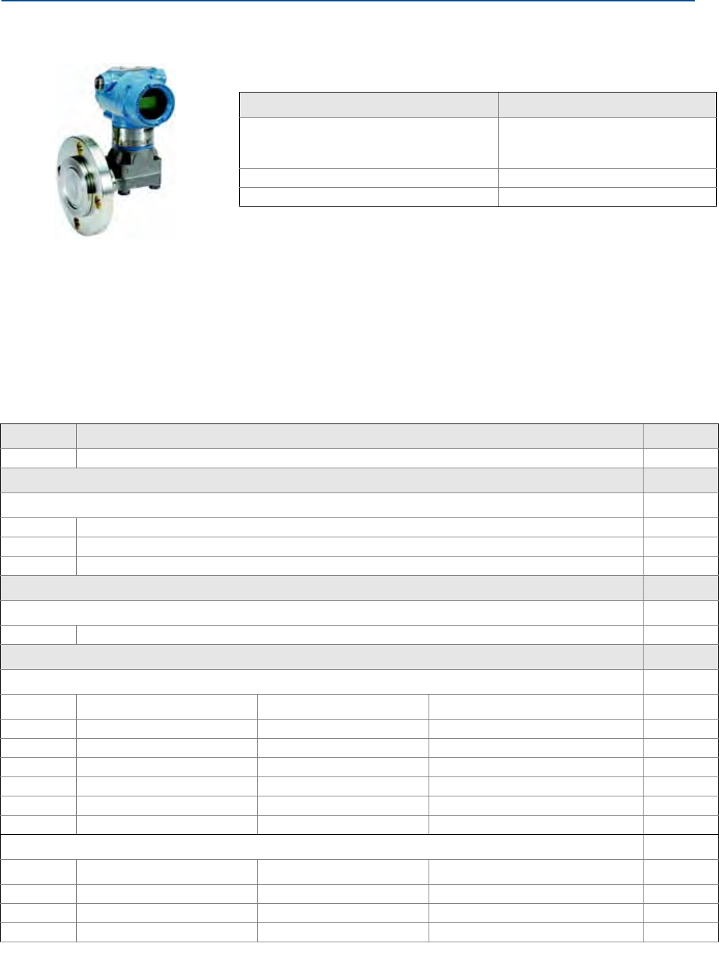
121
Reference Manual
00809-0100-4100, Rev AA
Appendix A: Specifications and Reference Data
June 2012
Specifications and Reference Data
A.5.5 Rosemount 3051L Level Transmitter
This ordering table contains the following Rosemount 3051L
configurations:
See Options for more details on each configuration.
Additional Information
Dimensional Drawings: page 93
Configuration Transmitter Output Code
4-20 mA HART®
-3051
-Enhanced 3051(1)
(1)The enhanced 4-20 mA HART device can be ordered with Transmitter Output option code
A plus any of the following new option codes: DA0, M4, QT, DZ, CR, CS, CT, HR5, HR7.
A
FOUNDATION™ fieldbus F
Profibus W
Table 6. Rosemount 3051L Level Transmitter Ordering Information
★ The Standard offering represents the most common options. The starred options (★) should be selected for best delivery.
__The Expanded offering is subject to additional delivery lead time.
Model Transmitter Type
3051L Level Transmitter
Pressure Range
Standard Standard
2–250 to 250 inH2O (–0,6 to 0,6 bar) ★
3–1000 to 1000 inH2O (–2,5 to 2,5 bar) ★
4–300 to 300 psi (–20,7 to 20,7 bar) ★
Transmitter Output
Standard Standard
XWireless ★
Process Connection Size, Material, Extension length (High Side)
Standard Standard
Code Process Connection Size Material Extension Length
G0(1) 2-in./DN 50/A 316L SST Flush Mount Only ★
H0(1) 2-in./DN 50 Alloy C-276 Flush Mount Only ★
J0 2-in./DN 50 Tantalum Flush Mount Only ★
A0(1) 3-in./DN 80 316L SST Flush Mount ★
A2(1) 3-in./DN 80 316L SST 2-in./50 mm ★
A4(1) 3-in./DN 80 316L SST 4-in./100 mm ★
Standard Standard
Code Process Connection Size Material Extension Length
A6(1) 3-in./DN 80 316L SST 6-in./150 mm ★
B0(1) 4-in./DN 100 316L SST Flush Mount ★
B2(1) 4-in./DN 100 316L SST 2-in./50 mm ★
3051L Level Transmitter

122
Reference Manual
00809-0100-4100, Rev AA
Appendix A: Specifications and Reference Data
June 2012
Specifications and Reference Data
B4(1) 4-in./DN 100 316L SST 4-in./100 mm ★
B6(1) 4-in./DN 100 316L SST 6-in./150 mm ★
C0(1) 3-in./DN 80 Alloy C-276 Flush Mount ★
C2(1) 3-in./DN 80 Alloy C-276 2-in./50 mm ★
C4(1) 3-in./DN 80 Alloy C-276 4-in./100 mm ★
C6(1) 3-in./DN 80 Alloy C-276 6-in./150 mm ★
D0(1) 4-in./DN 100 Alloy C-276 Flush Mount ★
D2(1) 4-in./DN 100 Alloy C-276 2-in./50 mm ★
D4(1) 4-in./DN 100 Alloy C-276 4-in./100 mm ★
D6(1) 4-in./DN 100 Alloy C-276 6-in./150 mm ★
E0 3-in./DN 80 Tantalum Flush Mount Only ★
F0 4-in./DN 100 Tantalum Flush Mount Only ★
Mounting Flange Size, Rating, Material (High Side)
Size Rating Material
Standard Standard
M2-in. ANSI/ASME B16.5 Class 150 CS ★
A3-in. ANSI/ASME B16.5 Class 150 CS ★
B4-in. ANSI/ASME B16.5 Class 150 CS ★
N2-in. ANSI/ASME B16.5 Class 300 CS ★
C3-in. ANSI/ASME B16.5 Class 300 CS ★
D4-in. ANSI/ASME B16.5 Class 300 CS ★
P2-in. ANSI/ASME B16.5 Class 600 CS ★
E3-in. ANSI/ASME B16.5 Class 600 CS ★
X(1) 2-in. ANSI/ASME B16.5 Class 150 SST ★
F(1) 3-in. ANSI/ASME B16.5 Class 150 SST ★
G(1) 4-in. ANSI/ASME B16.5 Class 150 SST ★
Y(1) 2-in. ANSI/ASME B16.5 Class 300 SST ★
H(1) 3-in. ANSI/ASME B16.5 Class 300 SST ★
J(1) 4-in. ANSI/ASME B16.5 Class 300 SST ★
Z(1) 2-in. ANSI/ASME B16.5 Class 600 SST ★
L(1) 3-in. ANSI/ASME B16.5 Class 600 SST ★
QDN 50 PN 10-40 per EN 1092-1 CS ★
RDN 80 PN 40 per EN 1092-1 CS ★
SDN 100 PN 40 per EN 1092-1 CS ★
VDN 100 PN 10/16 per EN 1092-1 CS ★
K(1) DN 50 PN 10-40 per EN 1092-1 SST ★
T(1) DN 80 PN 40 per EN 1092-1 SST ★
U(1) DN 100 PN 40 per EN 1092-1 SST ★
W(1) DN 100 PN 10/16 per EN 1092-1 SST ★
7(1) 4 in. ANSI/ASME B16.5 Class 600 SST ★
Expanded
1 — 10K per JIS B2238 CS
2 — 20K per JIS B2238 CS
3 — 40K per JIS B2238 CS
Table 6. Rosemount 3051L Level Transmitter Ordering Information
★ The Standard offering represents the most common options. The starred options (★) should be selected for best delivery.
__The Expanded offering is subject to additional delivery lead time.

123
Reference Manual
00809-0100-4100, Rev AA
Appendix A: Specifications and Reference Data
June 2012
Specifications and Reference Data
4(1) —10K per JIS B2238 316 SST
5(1) —20K per JIS B2238 316 SST
6(1) —40K per JIS B2238 316 SST
Seal Fill Fluid (High Side) Specific Gravity
Temperature Limits (Ambient Temperature of
70° F (21° C))
Standard Standard
ASyltherm XLT 0.85 -102 to 293 °F (-75 to 145 °C) ★
CSilicone 704 1.07 32 to 401 °F (0 to 205 °C) ★
DSilicone 200 0.93 -49 to 401 °F (-45 to 205 °C) ★
HInert (Halocarbon) 1.85 -49 to 320 °F (-45 to 160 °C) ★
GGlycerine and
Water
1.13 5 to 203 °F (-15 to 95 °C) ★
NNeobee M-20 0.92 5 to 401 °F (-15 to 205 °C) ★
PPropylene Glycol
and Water
1.02 5 to 203 F (-15 to 95 °C) ★
Low Pressure Side
Configuration
Flange
Adapter Diaphragm Material Sensor Fill Fluid
Standard Standard
11(1) Gage SST 316L SST Silicone ★
21(1) Differential SST 316L SST Silicone ★
22(1) Differential SST Alloy C-276 Silicone ★
2A(1) Differential SST 316L SST Inert (Halocarbon) ★
2B(1) Differential SST Alloy C-276 Inert (Halocarbon) ★
31(1) Tuned-System
Assembly with
Remote Seal
None 316L SST Silicone
(Requires Option Code S1)
★
O-ring
Standard Standard
AGlass-filled PTFE ★
Housing Material Conduit Entry Size
Standard Standard
PEngineered polymer No conduit entries ★
Wireless options (Requires option code X and Engineered Polymer housing code P)
Wireless Transmit Rate, Operating Frequency and Protocol
Standard Standard
WA3 User Configurable Transmit Rate, 2.4GHz WirelessHART ★
Antenna and SmartPower
Standard Standard
WP5 Internal Antenna, Compatible with Green Power Module (I.S. Power Module Sold Separately) ★
Options (Include with selected model number)
Seal Assemblies
Table 6. Rosemount 3051L Level Transmitter Ordering Information
★ The Standard offering represents the most common options. The starred options (★) should be selected for best delivery.
__The Expanded offering is subject to additional delivery lead time.

124
Reference Manual
00809-0100-4100, Rev AA
Appendix A: Specifications and Reference Data
June 2012
Specifications and Reference Data
Standard Standard
S1(2) Assembled to One Rosemount 1199 Seal (Requires 1199M) ★
Product Certifications
Standard Standard
I1 ATEX Intrinsic Safety and Dust ★
I2 INMETRO Intrinsic Safety ★
I3 China Intrinsic Safety ★
I5 FM Intrinsically Safe, Division 2 ★
I7 IECEx Intrinsic Safety ★
Bolting Material
Standard Standard
L4 Austenitic 316 SST Bolts ★
L5 ASTM A 193, Grade B7M bolts ★
L6 Alloy K-500 Bolts ★
L8 ASTM A 193 Class 2, Grade B8M Bolts ★
Display and Interface Options
Standard Standard
M5 LCD Display ★
Calibration Certification
Standard Standard
Q4 Calibration Certificate ★
QP Calibration Certificate and tamper evident seal ★
QG Calibration Certificate and GOST Verification Certificate ★
Material Traceability Certification
Standard Standard
Q8 Material Traceability Certification per EN 10204 3.1 ★
Toolkit Total System Performance Reports
Standard Standard
QZ Remote Seal System Performance Calculation Report ★
Configuration Buttons
Standard Standard
DZ Digital Zero Trim ★
Lower Housing Flushing Connection Options
Ring Material Number Size (NPT)
Standard Standard
F1 316 SST 11/4-18 NPT ★
F2 316 SST 21/4-18 NPT ★
F3 Alloy C-276 11/4-18 NPT ★
F4 Alloy C-276 21/4-18 NPT ★
F7 316 SST 11/2-14 NPT ★
Table 6. Rosemount 3051L Level Transmitter Ordering Information
★ The Standard offering represents the most common options. The starred options (★) should be selected for best delivery.
__The Expanded offering is subject to additional delivery lead time.

125
Reference Manual
00809-0100-4100, Rev AA
Appendix A: Specifications and Reference Data
June 2012
Specifications and Reference Data
F8 316 SST 21/2-14 NPT ★
F9 Alloy C-276 11/2-14 NPT ★
F0 Alloy C-276 21/2-14 NPT ★
Typical Model Number: 3051L 2 A A0 D 21 A A F1
(1)Materials of Construction comply with metallurgical requirements highlighted within NACE MR0175/ISO 15156 for sour oil field
production environments. Environmental limits apply to certain materials. Consult latest standard for details. Selected materials also
conform to NACE MR0103 for sour refining environments.
(2)“Assemble-to” items are specified separately and require a completed model number.
Table 6. Rosemount 3051L Level Transmitter Ordering Information
★ The Standard offering represents the most common options. The starred options (★) should be selected for best delivery.
__The Expanded offering is subject to additional delivery lead time.

126
Reference Manual
00809-0100-4100, Rev AA
Appendix A: Specifications and Reference Data
June 2012
Specifications and Reference Data
A.6 Options
Standard configuration
Unless otherwise specified, transmitter is shipped as follows:
Custom configuration
If Option Code C1 is ordered, the customer may specify the following data in addition to the
standard configuration parameters.
Output Information
Transmitter Information
LCD Display Configuration
Hardware Selectable Information
Signal Selection
Refer to the “Rosemount Enhanced 3051 Configuration Data Sheet” document number
00806-0100-4007.
Tagging (3 options available)
Standard SST hardware tag is wired to the transmitter. Tag character height is 0.125 in.
(3,18 mm), 56 characters maximum.
Tag may be permanently stamped on transmitter nameplate upon request, 56
characters maximum.
Tag may be stored in transmitter memory. Character limit is dependent on protocol.
–- WirelessHART: 32 characters
Optional Rosemount 304, 305, or 306 Integral Manifolds
Factory assembled to 3051C and 3051T transmitters. Refer to the following Product Data Sheet
(document number 00813-0100-4839 for Rosemount 304 and 00813-0100-4733 for
Rosemount 305 and 306) for additional information.
Engineering units
Differential/Gage:
Absolute/3051TA:
inH2O (Range 0, 1, 2, and 3)
psi (Range 4 and 5)
psi (all ranges)
Low Limit: 0 (engineering units above)
High Limit: Upper range limit
Output: Linear
Flange type: Specified model code option
Flange material: Specified model code option
O-ring material: Specified model code option
Drain/vent: Specified model code option
LCD Display: Installed or none
Alarm: High
Software tag: (Blank)

127
Reference Manual
00809-0100-4100, Rev AA
Appendix A: Specifications and Reference Data
June 2012
Specifications and Reference Data
Other seals
Refer to Product Data Sheet 00813-0100-4016 for additional information.
Output information
Output range points must be the same unit of measure. Available units of measure include:
Display and interface options
Digital display option provides diagnostic messages for local troubleshooting and has 90 degree
rotation capability for easy viewing.
M5 Digital Display
2-Line, 5-Digit LCD for 4-20 mA HART
Configuration buttons
The 3051 Wireless transmitter comes with a Digital Zero installed with the LCD digital display.
Bolts for flanges and adapters
Options permit bolts for flanges and adapters to be obtained in various materials
Standard material is plated carbon steel per ASTM A449, Type 1
Pressure
atm inH2O@4 °C g/cm2psi
mbar mmH2Okg/cm2torr
bar mmHg Pa cmH20@4 °C
inH20mmH2O@4 °C kPa cmHG@0 °C
inHg ftH20MPa ftH20@60 °F
hPa inH20@60 °F kg/SqM mH20@4 °C
mHg@0 °C Psf ftH2O@4 °C

128
Reference Manual
00809-0100-4100, Rev AA
Appendix A: Specifications and Reference Data
June 2012
Specifications and Reference Data
L4 Austenitic 316 Stainless Steel Bolts
L5 ASTM A 193, Grade B7M Bolts
L6 Alloy K-500 Bolts
Rosemount 3051C Coplanar Flange and 3051T bracket option
B4 Bracket for 2-in. Pipe or Panel Mounting
For use with the standard Coplanar
flange configuration
Bracket for mounting of transmitter on 2-in. pipe or panel
Stainless steel construction with stainless steel bolts
Rosemount 3051C Traditional Flange bracket options
B1 Bracket for 2-in. Pipe Mounting
For use with the traditional flange option
Bracket for mounting on 2-in. pipe
Carbon steel construction with carbon
steel bolts
Coated with polyurethane paint
B2 Bracket for Panel Mounting
For use with the traditional flange option
Bracket for mounting transmitter on wall
or panel
Carbon steel construction with carbon
steel bolts
Coated with polyurethane paint
B3 Flat Bracket for 2-in. Pipe Mounting
For use with the traditional flange option
Bracket for vertical mounting of transmitter on 2-in. pipe
Carbon steel construction with carbon
steel bolts
Coated with polyurethane paint
B7 B1 Bracket with SST Bolts
Same bracket as the B1 option with Series 300 stainless steel bolts
B8 B2 Bracket with SST Bolts
Same bracket as the B2 option with Series 300 stainless steel bolts
B9 B3 Bracket with SST Bolts
Same bracket as the B3 option with Series 300 stainless steel bolts

129
Reference Manual
00809-0100-4100, Rev AA
Appendix A: Specifications and Reference Data
June 2012
Specifications and Reference Data
BA Stainless Steel B1 Bracket with SST Bolts
B1 bracket in stainless steel with Series 300 stainless steel bolts
BC Stainless Steel B3 Bracket with SST Bolts
B3 bracket in stainless steel with Series 300 stainless steel bolts
Shipping weights
Table 7. Transmitter weights without options
Table 8. 3051L weights without options
Transmitter Add weight In lb (kg)
3051C 3.9 (1,8)
3051L Table 8
3051T 2.3 (1,0)
Flange
Flush
lb. (kg)
2-in. Ext.
lb (kg)
4-in. Ext.
lb (kg)
6-in. Ext.
lb (kg)
2-in., 150 12.5 (5,7) ———
3-in., 150 17.5 (7,9) 19.5 (8,8) 20.5 (9,3) 21.5 (9,7)
4-in., 150 23.5 (10,7) 26.5 (12,0) 28.5 (12,9) 30.5 (13,8)
2-in., 300 17.5 (7,9) ———
3-in., 300 22.5 (10,2) 24.5 (11,1) 25.5 (11,6) 26.5 (12,0)
4-in., 300 32.5 (14,7) 35.5 (16,1) 37.5 (17,0) 39.5 (17,9)
2-in., 600 15.3 (6,9) ———
3-in., 600 25.2 (11,4) 27.2 (12,3) 28.2 (12,8) 29.2 (13,2)
DN 50/PN 40 13.8 (6,2) ———
DN 80/PN 40 19.5 (8,8) 21.5 (9,7) 22.5 (10,2) 23.5 (10,6)
DN 100/PN 10/16 17.8 (8,1) 19.8 (9,0) 20.8 (9,5) 21.8 (9,9)
DN 100/PN 40 23.2 (10,5) 25.2 (11,5) 26.2 (11,9) 27.2 (12,3)

130
Reference Manual
00809-0100-4100, Rev AA
Appendix A: Specifications and Reference Data
June 2012
Specifications and Reference Data
Table 9. Transmitter options weights
Code Option
Add
lb (kg)
J, K, L, M Stainless Steel Housing(T) 3.9 (1,8)
J, K, L, M Stainless Steel Housing (C, L, H, P) 3.1 (1,4)
M5 LCD Display for Aluminum Housing 0.5 (0,2)
M6 LCD Display for SST Housing 1.25 (0,6)
B4 SST Mounting Bracket for Coplanar Flange 1.0 (0,5)
B1 B2 B3 Mounting Bracket for Traditional Flange 2.3 (1,0)
B7 B8 B9 Mounting Bracket for Traditional Flange 2.3 (1,0)
BA, BC SST Bracket for Traditional Flange 2.3 (1,0)
H2 Traditional Flange 2.4 (1,1)
H3 Traditional Flange 2.7 (1,2)
H4 Traditional Flange 2.6 (1,2)
H7 Traditional Flange 2.5 (1,1)
FC Level Flange—3 in., 150 10.8 (4,9)
FD Level Flange—3 in., 300 14.3 (6,5)
FA Level Flange—2 in., 150 10.7 (4,8)
FB Level Flange—2 in., 300 14.0 (6,3)
FP DIN Level Flange, SST, DN 50, PN 40 8.3 (3,8)
FQ DIN Level Flange, SST, DN 80, PN 40 13.7 (6,2)

131
Reference Manual
00809-0100-4100, Rev AA
Appendix A: Specifications and Reference Data
June 2012
Specifications and Reference Data
A.7 Spare parts
Model 3051C Sensor Modules (Min. Span/Range)
Silicone Fill
Part Number
Note: One spare part is recommended for every 50 transmitters.
Note: Listed by Range and Process Isolator Order Numbers.
–3 to 3/0.1 inH2O, Range 0 (includes Traditional SST flange and SST bolts).
316L SST 03031-1045-0002
–25 to 25 inH2O/0.5 inH2O, Range 1
316L SST 03031-1045-0012
Alloy C-276 03031-1045-0013
Alloy 400 03031-1045-0014
Gold-plated Alloy 400 03031-1045-0016
Gold-plated 316 SST 03031-1045-0017
–250 to 250 inH2O/2.5 inH2O, Range 2
316L SST 03031-1045-0022
Alloy C-276 03031-1045-0023
Alloy 400 03031-1045-0024
Tantalum 03031-1045-0025
Gold-plated Alloy 400 03031-1045-0026
Gold-plated 316 SST 03031-1045-0027
–1000 to 1000 inH2O/10 inH2O, Range 3
316L SST 03031-1045-0032
Alloy C-276 03031-1045-0033
Alloy 400 03031-1045-0034
Tantalum 03031-1045-0035
Gold-plated Alloy 400 03031-1045-0036
Gold-plated 316 SST 03031-1045-0037
–300 to 300 psi/3 psi, Range 4
316L SST 03031-1045-2042
Alloy C-276 03031-1045-2043
Alloy 400 03031-1045-2044
Tantalum 03031-1045-2045
Gold-plated Alloy 400 03031-1045-2046
Gold-plated 316 SST 03031-1045-2047

132
Reference Manual
00809-0100-4100, Rev AA
Appendix A: Specifications and Reference Data
June 2012
Specifications and Reference Data
–2000 to 2000/20 psi, Range 5
316L SST 03031-1045-2052
Alloy C-276 03031-1045-2053
Alloy 400 03031-1045-2054
Tantalum 03031-1045-2055
Gold-plated Alloy 400 03031-1045-2056
Gold-plated 316 SST 03031-1045-2057
Rosemount 3051C gage and differential sensor modules (Min. Span/Range)
Silicone fill
Part number
Note: One spare part is recommended for every 50 transmitters.
Note: Listed by Range and Process Isolator Order Numbers.
Gage pressure range Differential pressure range
Range 1 –25 to 25 in H2O/0.5 in H2O –25 to 25 in H2O/0.5 in H2O
316L SST 03031-1045-0012
Alloy C-276 03031-1045-0013
Alloy 400 03031-1045-0014
Gold-plated Alloy 400 03031-1045-0016
Gold-plated 316 SST 03031-1045-0017
Range 2 –250 to 250 inH2O/2.5 inH2O–250 to 250 inH2O/2.5 inH2O
316L SST 03031-1045-0022
Alloy C-276 03031-1045-0023
Alloy 400 03031-1045-0024
Tantalum 03031-1045-0025
Gold-plated Alloy 400 03031-1045-0026
Gold-plated 316 SST 03031-1045-0027
Range 3 –407 to 1000 inH2O/10 inH2O-1000 to 1000 inH2O/10 inH2O
316L SST 03031-1045-0032
Alloy C-276 03031-1045-0033
Alloy 400 03031-1045-0034
Tantalum 03031-1045-0035
Gold-plated Alloy 400 03031-1045-0036
Gold-plated 316 SST 03031-1045-0037

133
Reference Manual
00809-0100-4100, Rev AA
Appendix A: Specifications and Reference Data
June 2012
Specifications and Reference Data
Range 4 –14.2 to 300 psi/3 psi -300 to 300 psi/3 psi
316L SST 03031-1045-2042
Alloy C-276 03031-1045-2043
Alloy 400 03031-1045-2044
Tantalum 03031-1045-2045
Gold-plated Alloy 400 03031-1045-2046
Gold-plated 316 SST 03031-1045-2047
Range 5 –14.2 to 2000 psi/20 psi -2000 to 2000psi/20 psi
316L SST 03031-1045-2052
Alloy C-276 03031-1045-2053
Alloy 400 03031-1045-2054
Tantalum 03031-1045-2055
Gold-plated Alloy 400 03031-1045-2056
Gold-plated 316 SST 03031-1045-2057
Rosemount 3051C absolute sensor modules (Min. Span/Range)
Silicone fill
Part number
Note: One spare part is recommended for every 50 transmitters.
Note: Listed by Range and Process Isolator Order Numbers.
Range 1, 0 to 30 psia/0.3 psia
316L SST 03031-2020-0012
Alloy C-276 03031-2020-0013
Alloy 400 03031-2020-0014
Gold-plated Alloy 400 03031-2020-0016
Gold-plated 316 SST 03031-2020-0017
Range 2, 0 to 150/1.5 psia
316L SST 03031-2020-0022
Alloy C-276 03031-2020-0023
Alloy 400 03031-2020-0024
Gold-plated Alloy 400 03031-2020-0026
Gold-plated 316 SST 03031-2020-0027
Range 3, 0 to 800 psia/8 psia
316L SST 03031-2020-0032
Alloy C-276 03031-2020-0033
Alloy 400 03031-2020-0034
Gold-plated Alloy 400 03031-2020-0036
Gold-plated 316 SST 03031-2020-0037

134
Reference Manual
00809-0100-4100, Rev AA
Appendix A: Specifications and Reference Data
June 2012
Specifications and Reference Data
Range 4, 0 to 400 psia/40 psia
316L SST 03031-2020-0042
Alloy C-276 03031-2020-0043
Alloy 400 03031-2020-0044
Gold-plated Alloy 400 03031-2020-0046
Gold-plated 316 SST 03031-2020-0047
Rosemount 3051T Sensor Modules (Min. Span/Range)
Silicone Fill
Part Number
Note: One spare part is recommended for every 50 transmitters.
Range 1
Gage pressure range
0-0.3/30 psig
Aluminum, 316L SST Isolator
1/4 –18 NPT Female 03031-3112-3112
1/2 –14 NPT Female 03031-3102-3112
G1/2 A DIN 16288 Male 03031-3132-3112
Aluminum, Alloy C-276 Isolator
1/4 –18 NPT Female 03031-3112-3113
1/2 –14 NPT Female 03031-3102-3113
SST, 316L SST Isolator
1/4 –18 NPT Female 03031-3111-3112
1/2 –14 NPT Female 03031-3101-3112
SST, AlloyC-276 Isolator
1/4 –18 NPT Female 03031-3111-3113
1/2 –14 NPT Female 03031-3101-3113
Range 2 0-1.5/150 psig
Aluminum, 316L SST Isolator
1/4 –18 NPT Female 03031-3112-3122
1/2 –14 NPT Female 03031-3102-3122
G1/2 A DIN 16288 Male 03031-3132-3122
Aluminum, Alloy C-276 Isolator
1/4 –18 NPT Female 03031-3112-3122
1/2 –14 NPT Female 03031-3102-3122
G1/2 A DIN 16288 Male 03031-3132-3122

135
Reference Manual
00809-0100-4100, Rev AA
Appendix A: Specifications and Reference Data
June 2012
Specifications and Reference Data
Aluminum, Alloy C-276 Isolator
1/4 –18 NPT Female 03031-3112-3123
1/2 –14 NPT Female 03031-3102-3123
SST, 316L SST Isolator
¼ –18 NPT Female 03031-3111-3122
1/2 –14 NPT Female 03031-3101-3122
SST, AlloyC-276 Isolator
1/4 –18 NPT Female 03031-3111-3123
1/2 –14 NPT Female 03031-3101-3123
Range 3 0-8/800 psig
Aluminum, 316L SST Isolator
1/4 –18 NPT Female 03031-3112-3132
1/2 –14 NPT Female 03031-3102-3132
G1/2 A DIN 16288 Male 03031-3132-3132
Aluminum, Alloy C-276 Isolator
1/4 –18 NPT Female 03031-3112-3133
1/2 –14 NPT Female 03031-3102-3133
SST, 316L SST Isolator
1/4 –18 NPT Female 03031-3111-3132
1/2 –14 NPT Female 03031-3101-3132
SST, AlloyC-276 Isolator
1/4 –18 NPT Female 03031-3111-3133
1/2 –14 NPT Female 03031-3101-3133
Range4 0-40/4,000 psig
Aluminum, 316L SST Isolator
1/4 –18 NPT Female 03031-3112-3142
1/2 –14 NPT Female 03031-3102-3142
G1/2 A DIN 16288 Male 03031-3132-3142
Aluminum, Alloy C-276 Isolator
1/4 –18 NPT Female 03031-3112-3143
1/2 –14 NPT Female 03031-3102-3143
SST, 316L SST Isolator
1/4 –18 NPT Female 03031-3111-3142
1/2 –14 NPT Female 03031-3101-3142
SST, AlloyC-276 Isolator
1/4 –18 NPT Female 03031-3111-3143
1/2 –14 NPT Female 03031-3101-3143

136
Reference Manual
00809-0100-4100, Rev AA
Appendix A: Specifications and Reference Data
June 2012
Specifications and Reference Data
Range 1
Gage pressure range
0-0.3/30 psia
Aluminum, 316L SST Isolator
1/4 –18 NPT Female 03031-3112-3012
1/2 –14 NPT Female 03031-3102-1012
G1/2 A DIN 16288 Male 03031-3132-3012
Aluminum, Alloy C-276 Isolator
1/4 –18 NPT Female 03031-3112-3013
1/2 –14 NPT Female 03031-3102-3013
SST, 316L SST Isolator
1/4 –18 NPT Female 03031-3111-3012
1/2 –14 NPT Female 03031-3101-3012
SST, AlloyC-276 Isolator
1/4 –18 NPT Female 03031-3111-3013
1/2 –14 NPT Female 03031-3101-3013
Range 2 0-1.5/150 psia
Aluminum, 316L SST Isolator
1/4 –18 NPT Female 03031-3112-3022
1/2 –14 NPT Female 03031-3112-3022
G1/2 A DIN 16288 Male 03031-3132-3022
Aluminum, Alloy C-276 Isolator
1/4 –18 NPT Female 03031-3112-3023
1/2 –14 NPT Female 03031-3102-3023
SST, 316L SST Isolator
1/4 –18 NPT Female 03031-3111-3022
1/2 –14 NPT Female 03031-3101-3022
SST, AlloyC-276 Isolator
1/4–18 NPT Female 03031-3111-3023
1/2 –14 NPT Female 03031-3101-3023
Range 3 0-8/800 psia
Aluminum, 316L SST Isolator
1/4–18 NPT Female 03031-3112-3032
1/2 –14 NPT Female 03031-3102-3032
G1/2 A DIN 16288 Male 03031-3132-3032
Aluminum, Alloy C-276 Isolator
1/4 –18 NPT Female 03031-3112-3033
1/2 –14 NPT Female 03031-3102-3033

137
Reference Manual
00809-0100-4100, Rev AA
Appendix A: Specifications and Reference Data
June 2012
Specifications and Reference Data
SST, 316L SST Isolator
1/4 –18 NPT Female 03031-3111-3032
1/2 –14 NPT Female 03031-3101-3032
SST, AlloyC-276 Isolator
1/4 –18 NPT Female 03031-3111-3033
1/2 –14 NPT Female 03031-3101-3033
Range 4 0-40/4,000 psia
Aluminum, 316L SST Isolator
1/4 –18 NPT Female 03031-3112-3042
1/2 –14 NPT Female 03031-3102-3042
G1/2 A DIN 16288 Male 03031-3132-3042
Aluminum, Alloy C-276 Isolator
1/4 –18 NPT Female 03031-3112-3043
1/2 –14 NPT Female 03031-3102-3043
SST, 316L SST Isolator
1/4 –18 NPT Female 03031-3111-3042
1/2 –14 NPT Female 03031-3101-3042
SST, AlloyC-276 Isolator
1/4 –18 NPT Female 03031-3111-3043
1/2 –14 NPT Female 03031-3101-3043
Range 5 0-2000/10,000 psia
Aluminum, 316L SST Isolator
1/4–18 NPT Female 03031-3112-3052
1/2 –14 NPT Female 03031-3102-3052
Autoclave type F-250-C 03031-3122-3052
Aluminum, Alloy C-276 Isolator
1/4 –18 NPT Female 03031-3112-3053
1/2 –14 NPT Female 03031-3102-3053
SST, 316L SST Isolator
1/4 –18 NPT Female 03031-3111-3052
1/2 –14 NPT Female 03031-3101-3052
Autoclave type F-250-C 03031-3121-3052
SST, AlloyC-276 Isolator
1/4–18 NPT Female 03031-3111-3053
1/2 –14 NPT Female 03031-3101-3053

138
Reference Manual
00809-0100-4100, Rev AA
Appendix A: Specifications and Reference Data
June 2012
Specifications and Reference Data
LCD Display Part number
LCD Display for 3051 Wireless with Polymer Housing
LCD Display for 3051 WirelessHART 03151-9010-0001
Electrical housings Part number
Standard - Polymer
Engineered Polymer
Housing covers (include o-ring) Part number
Wireless Battery Cover - Polymer
LCD Display Cover - Polymer
Flanges Part number
Differential Coplanar Flange
316 SST 03031-0388-0022
Cast Alloy C-276 03031-0388-0023
Cast Alloy 400 03031-0388-0024
Nickel-plated carbon steel 03031-0388-0025
Gage/Absolute Coplanar Flange
316 SST 03031-0388-1022
Cast Alloy C-276 03031-0388-1023
Cast Alloy 400 03031-0388-1024
Nickel-plated carbon steel 03031-0388-1025
Coplanar flange alignment screw (package of 12) 03031-0309-0001
Traditional Flange
316 SST 03031-0320-0002
Cast Alloy C-276 03031-0320-0003
Cast Alloy 400 03031-0320-0004
316 SST - DIN Compliant (Option Code HJ) 03031-1350-0012
Level Flange, Vertical Mount
2 in., class 150, SST 03031-0393-0221
2 in., class 300, SST 03031-0393-0222
3 in., class 150, SST 03031-0393-0231
3 in., class 300, SST 03031-0393-0232
DIN, DN 50, PN 40 03031-0393-1002
DIN, DN 80, PN 40 03031-0393-1012

139
Reference Manual
00809-0100-4100, Rev AA
Appendix A: Specifications and Reference Data
June 2012
Specifications and Reference Data
Flange adapter kits (each kit contains parts for one DP transmitter or two GP/AP
transmitters) Part number
CS bolts, glass-filled PTFE O-Rings
SST adapters 03031-1300-0002
Cast Alloy C-276 adapters 03031-1300-0003
Alloy 400 adapters 03031-1300-0004
Nickel-plated carbon steel adapters 03031-1300-0005
SST bolts, glass-filled PTFE O-Rings
SST adapters 03031-1300-0012
Cast Alloy C-276 adapters 03031-1300-0013
Alloy 400 adapters 03031-1300-0014
Nickel-plated carbon steel adapters 03031-1300-0015
CS bolts, graphite-filled PTFE O-Rings
SST adapters 03031-1300-0102
Cast Alloy C-276 adapters 03031-1300-0103
Alloy 400 adapters 03031-1300-0104
Nickel-plated carbon steel adapters 03031-1300-0105
SST bolts, graphite-filled PTFE O-Rings
SST adapters 03031-1300-0112
Cast Alloy C-276 adapters 03031-1300-0113
Alloy 400 adapters 03031-1300-0114
Nickel-plated carbon steel adapters 03031-1300-0115
Flange adapters Part number
1/2 - 14 NPT Adapters
316 SST 02024-0069-0002
Cast Alloy C-276 02024-0069-0003
Cast Alloy 400 02024-0069-0004
Nickel-plated carbon steel 02024-0069-0005
Socket Weld Adapters
316 SST 02024-0069-1002
Cast Alloy C-276 02024-0069-1003
Cast Alloy 400 02024-0069-1004

140
Reference Manual
00809-0100-4100, Rev AA
Appendix A: Specifications and Reference Data
June 2012
Specifications and Reference Data
O-Ring packages (package of 12) Part number
Electronics housing, cover 03031-0232-0001
Electronics housing, module 03031-0233-0001
Process flange, glass-filled PTFE (White) 03031-0234-0001
Process flange, graphite-filled PTFE (Black) 03031-0234-0002
Flange adapter, glass-filled PTFE (Light Brown) 03031-0242-0001
Flange adapter, graphite-filled PTFE (Black) 03031-0242-0002
Bolt kits Part number
COPLANAR FLANGE
Flange Bolt Kit {44mm (1.75 in.)} (set of 4)
Carbon steel 03031-0312-0001
316 SST 03031-0312-0002
ASTM A 193, Grade B7M 03031-0312-0003
Alloy K-500 03031-0312-0004
Flange/Adapter Bolt Kit {73mm (2.88 in.)} (set of 4)
Carbon steel 03031-0306-0001
316 SST 03031-0306-0002
ASTM A 193, Grade B7M 03031-0306-0003
Alloy K-500 03031-0306-0004
TRADITIONAL FLANGE
Differential Flange/Adapter Bolt Kit {44mm (1.75 in.)} (set of 8)
Carbon steel 03031-0307-0001
316 SST 03031-0307-0002
ASTM A 193, Grade B7M 03031-0307-0003
Alloy K-500 03031-0307-0004
Gage/Absolute Flange/Adapter Bolt Kit {44mm (1.75 in.)} (set of 6)
Carbon steel 03031-0307-1001
316 SST 03031-0307-1002
ASTM A 193, Grade B7M 03031-0307-1003
Alloy K-500 03031-0307-1004
Conventional Manifold/Traditional Flange Bolts
Carbon steel Use bolts supplied with
manifold
316 SST Use bolts supplied with
manifold
Level Flange, Vertical Mount Bolt Kit (Set of 4)
Carbon steel 03031-0395-0001
316 SST 03031-0395-0002

141
Reference Manual
00809-0100-4100, Rev AA
Appendix A: Specifications and Reference Data
June 2012
Specifications and Reference Data
Drain/Vent valve kits (each kit contains parts for one transmitter) Part number
Differential Drain/Vent Kits
316 SST stem and seat kit 01151-0028-0022
Alloy C-276 stem and seat kit 01151-0028-0023
Alloy K-500 stem and Alloy 400 seat kit 01151-0028-0024
316 SST ceramic ball drain/vent kit 03031-0378-0022
Alloy C-276 ceramic ball drain/vent kit 03031-0378-0023
Alloy 400/K-500 ceramic ball drain/vent kit 03031-0378-0024
Gage/Absolute Drain/Vent Kits
316 SST stem and seat kit 01151-0028-0012
Alloy C-276 stem and seat kit 01151-0028-0013
Alloy K-500 stem and Alloy 400 seat kit 01151-0028-0014
316 SST ceramic ball drain/vent kit 03031-0378-0012
Alloy C-276 ceramic ball drain/vent kit 03031-0378-0013
Alloy 400/K-500 ceramic ball drain/vent kit 03031-0378-0014
Mounting brackets Part number
3051C and 3051L Coplanar Flange Bracket kit
B4 bracket, SST, 2-in. pipe mount, SST bolts 03031-0189-0003
3051T Inline Bracket Kit
B4 bracket, SST, 2-in. pipe mount, SST bolts 03031-0189-0004
3051C Traditional Flange Bracket Kits
B1 bracket, 2-in. pipe mount, CS bolts 03031-0313-0001
B2 bracket, panel mount, CS bolts 03031-0313-0002
B3 flat bracket, 2-in. pipe mount, CS bolts 03031-0313-0003
B7 (B1 bracket, SST bolts) 03031-0313-0007
B8 (B2 bracket, SST bolts) 03031-0313-0008
B9 (B3 bracket, SST bolts) 03031-0313-0009
BA (SST B1 bracket, SST bolts) 03031-0313-0011
BC (SST B3 bracket, SST bolts) 03031-0313-0013

142
Reference Manual
00809-0100-4100, Rev AA
Appendix A: Specifications and Reference Data
June 2012
Specifications and Reference Data

Reference Manual
00809-0100-4100, Rev AA
Appendix B: Product Certifications
June 2012
143
Product Certifications
Appendix B Product Certifications
Wireless Certifications . . . . . . . . . . . . . . . . . . . . . . . . . . . . . . . . . . . . . . . . . . . . . . . . . . . . . . . page 143
B.1 Wireless Certifications
B.1.1 Approved manufacturing locations
Rosemount Inc. — Chanhassen, Minnesota USA
Fisher-Rosemount GmbH & Co. — Wessling, Germany
Emerson Process Management Asia Pacific Private Limited — Singapore
Beijing Rosemount Far East Instrument Co., LTD — Beijing, China
B.1.2 European directive information
The EC declaration of conformity can be found on . The most recent revision can be found at
www.rosemount.com.
B.1.3 Telecommunication compliance
All wireless devices require certification to ensure that they adhere to regulations regarding the
use of the RF spectrum. Nearly every country requires this type of product certification.
Emerson is working with governmental agencies around the world to supply fully compliant
products and remove the risk of violating country directives or laws governing wireless device
usage.
B.1.4 FCC and IC
This device complies with Part 15 of the FCC Rules. Operation is subject to the following
conditions: This device may not cause harmful interference. This device must accept any
interference received, including interference that may cause undesired operation. This device
must be installed to ensure a minimum antenna separation distance of 20 cm from all persons.
B.1.5 Ordinary location certification for FM
As standard, the transmitter has been examined and tested to determine that the design meets
basic electrical, mechanical, and fire protection requirements by FM, a nationally recognized
testing laboratory (NRTL) as accredited by the Federal Occupational Safety and Health
Administration (OSHA).

144
Reference Manual
00809-0100-4100, Rev AA
Appendix B: Product Certifications
June 2012
Product Certifications
B.1.6 North American certifications
Factory Mutual (FM) approvals
I5 FM Intrinsically Safe, Non-Incendive, and Dust Ignition-proof.
Intrinsically Safe for Class I/II/III, Division 1, Groups A, B, C, D, E, F, and G.
Zone Marking: Class I, Zone 0, AEx ia llC
Temperature Codes T4 (Tamb = -50 to 70 °C)
Non-Incendive for Class I, Division 2, Groups A, B, C, and D.
Dust Ignition-proof for Class II/III, Division 1, Groups E, F, and G.
Ambient temperature limits: -50 to 85 °C
For use with Rosemount power module P/N 00753-9220-0001 only.
Enclosure Type 4X / IP66/68
B.1.7 CSA - Canadian Standards Association
I6 CSA Intrinsically Safe
Intrinsically Safe for Class I, Division 1, Groups A, B, C, and D.
Temp Code T3C
Enclosure Type 4X / IP66/68
For use with Rosemount power module P/N 00753-9220-0001 only.
B.1.8 European certifications
I1 ATEX Intrinsic Safety
Certificate No.: BAS01ATEX1303X II 1G
Ex ia IIC T4 (Ta = -60 °C to 70 °C)
For use with Rosemount power module options 00753-9220-0001 only.
IP66/68
1180
Special Conditions for Safe Use (X)
The surface resistivity of the antenna is greater than one gigaohm. To avoid electrostatic charge
build-up, it must not be rubbed or cleaned with solvents or a dry cloth.
I7 IECEx Intrinsic Safety
Certificate No.: IECEx BAS 04.0017X
Ex ia IIC T4 (Ta = -60 °C to 70 °C)
For use with Rosemount power module options 00753-9220-0001 only.
IP66/68
Special Conditions for Safe Use (X)
The surface resistivity of the antenna is greater than one gigaohm. To avoid electrostatic charge
build-up, it must not be rubbed or cleaned with solvents or a dry cloth.

145
Reference Manual
00809-0100-4100, Rev AA
Appendix B: Product Certifications
June 2012
Product Certifications
B.1.9 Japanese Certifications
I4 TIIS Intrinsic Safety
Ex ia IIC T4
B.1.10 China (NEPSI) Certifications
I3 China Intrinsic Safety
Certificate No. (manufactured in Chanhassen, MN): GYJ081078
Certificate No. (manufactured in Beijing, China): GYJ06367
Certificate No. (manufactured in Singapore): GYJ06365
Ex ia IIC T4
Special Conditions for Safe Use (X)
See appropriate certificate.
Certificate Description
TC18649 2051_CD/CG/LD/LG
TC18650 2051_CA/TA/TG/LA
TC18657 2051FA/SFC/SFP

146
Reference Manual
00809-0100-4100, Rev AA
Appendix B: Product Certifications
June 2012
Product Certifications

Reference Manual
00809-0100-4100, Rev AA
June 2012
Standard Terms and Conditions of Sale can be found at www.rosemount.com/terms_of_sale
The Emerson logo is a trademark and service mark of Emerson Electric Co.
Rosemount. the Rosemount logotype, and SMART FAMILY are registered trademarks of Rosemount Inc.
Coplanar is a trademark of Rosemount Inc.
Halocarbon is a trademark of the Halocarbon Products Corporation.o.
Fluorinert is a registered trademark of Minnesota Mining and Manufacturing Company Corporation
Syltherm 800 and D.C. 200 are registered trademarks of Dow Corning Corporation.
Neobee M-20 is a registered trademark of PVO International, Inc.
HART is a registered trademark of the HART Communication Foundation.
Foundation fieldbus is a registered trademark of the Fieldbus Foundation.
All other marks are the property of their respective owners.
© June 2012 Rosemount, Inc. All rights reserved.
Emerson Process Management
GmbH & Co.
Argelsrieder Feld 3
82234 Wessling
Germany
Tel 49 (8153) 9390
Fax 49 (8153) 939172
Emerson Process Management Asia
Pacific Private Limited
1 Pandan Crescent
Singapore 128461
T (65) 6777 8211
F (65) 6777 0947
Enquiries@AP.EmersonProcess.com
Beijing Rosemount Far East
Instrument Co., Limited
No. 6 North Street,
Hepingli, Dong Cheng District
Beijing 100013, China
T (86) (10) 6428 2233
F (86) (10) 6422 8586
Emerson Process Management
Rosemount Measurement
8200 Market Boulevard
Chanhassen MN 55317 USA
Tel (USA) 1 800 999 9307
Tel (International) +1 952 906 8888
Fax +1 952 906 8889