Rosslare ACQ4XXB Anti-Vandal Standalone Controllers User Manual AC Q4x Series Installation and Programming Manual
Rosslare Enterprises Ltd Anti-Vandal Standalone Controllers AC Q4x Series Installation and Programming Manual
Rosslare >
15_AC-Q42HB UserMan
AC-Q4x Series
Anti-Vandal Standalone
Controllers
Installation and Programming Manual
Models:
AC-Q41HB
AC-Q41HP
AC-Q41SB
AC-Q42HB
AC-Q42HP
AC-Q42SB
Copyright © 2017 by Rosslare. All rights reserved.
This manual and the information contained herein are proprietary to ROSSLARE
ENTERPRISES LIMITED and/or its related companies and/or subsidiaries’
(hereafter: "ROSSLARE"). Only ROSSLARE and its customers have the right to
use the information.
No part of this manual may be re-produced or transmitted in any form or by any
means, electronic or mechanical, for any purpose, without the express written
permission of ROSSLARE.
ROSSLARE owns patents and patent applications, trademarks, copyrights, or
other intellectual property rights covering the subject matter in this manual.
TEXTS, IMAGES, AND ILLUSTRATIONS INCLUDING THEIR ARRANGEMENT IN
THIS DOCUMENT ARE SUBJECT TO THE PROTECTION OF COPYRIGHT LAWS
AND OTHER LEGAL RIGHTS WORLDWIDE. THEIR USE, REPRODUCTION, AND
TRANSMITTAL TO THIRD PARTIES WITHOUT EXPRESS WRITTEN PERMISSION
MAY RESULT IN LEGAL PROCEEDINGS.
The furnishing of this manual to any party does not give that party or any third
party any license to these patents, trademarks, copyrights or other intellectual
property rights, except as expressly provided in any written agreement of
ROSSLARE.
ROSSLARE reserves the right to revise and change this document at any time,
without being obliged to announce such revisions or changes beforehand or
after the fact.

Table of Contents
AC-Q4x Series Installation and Programming Manual iii
Table of Contents
1. Introduction ................................................................ 9
1.1 Controller Types ...................................................................... 9
1.2 Box Content ......................................................................... 10
1.3 Ancillary Equipment .............................................................. 10
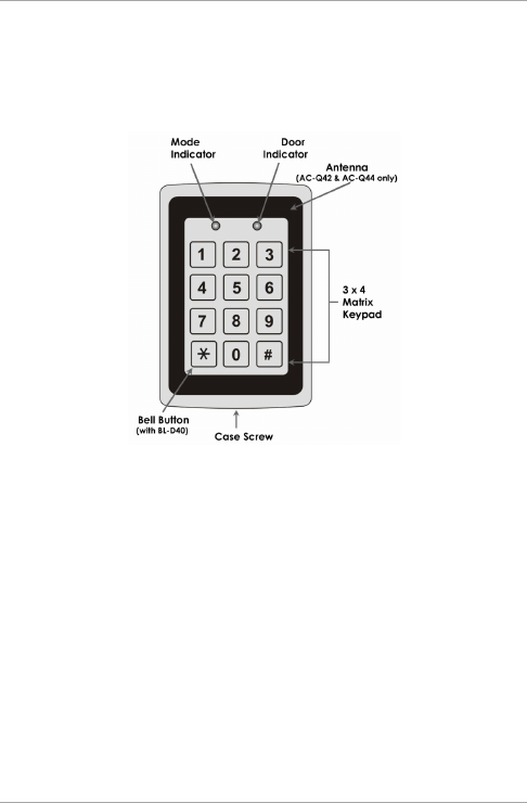
1.4 Front Panel Description .......................................................... 11
2. Technical Specifications ............................................ 12
3. Installation ................................................................ 14
3.1 Mounting ............................................................................. 14
3.2 Wiring .................................................................................. 15
3.2.1 Pre-wired Models .......................................................................... 16
3.2.2 Terminal Block Models .................................................................. 20
4. Operation .................................................................. 24
4.1 Modes of Operation .............................................................. 24
4.1.1 Normal Mode ............................................................................... 24
4.1.2 Secure Mode ................................................................................ 24
4.1.3 Bypass Mode ................................................................................ 24
4.2 User Levels ............................................................................ 25
4.3 Switching Operational Modes ................................................ 26
4.3.1 From Normal to Secure Mode ....................................................... 26
4.3.2 From Secure to Normal Mode ....................................................... 26
4.3.3 From Normal to Bypass Mode ....................................................... 27
4.3.4 From Bypass to Normal Mode ....................................................... 27
4.4 Auxiliary Input and Output..................................................... 27
4.5 REX Button ........................................................................... 27

Table of Contents
iv AC-Q4x Series Installation and Programming Manual
4.6 Tamper Feature ..................................................................... 28
4.7 Lockout Feature (Keypad/Card Tamper) .................................. 28
4.8 BL-D40 External Sounder ....................................................... 29
5. Programming ............................................................ 30
5.1 Entering the Programming Mode ........................................... 31
5.2 Exiting the Programming Mode .............................................. 32
5.3 Changing the Open Code ...................................................... 32
5.4 Changing the Auxiliary Code ................................................. 33
5.5 Changing the Programming Code .......................................... 34
5.6 Changing the Normal/Secure Code ........................................ 34
5.7 Changing the Normal/Bypass Code ........................................ 35
5.8 Setting Fail Safe/Secure Operation, Tamper Siren and Lock Strike
Release Time ......................................................................... 36
5.9 Setting Auxiliary Modes ......................................................... 37
5.9.1 Auxiliary Mode 0 .......................................................................... 39
5.9.2 Auxiliary Mode 1 .......................................................................... 39
5.9.3 Auxiliary Mode 2 .......................................................................... 39
5.9.4 Auxiliary Mode 3 .......................................................................... 40
5.9.5 Auxiliary Mode 4 .......................................................................... 40
5.9.6 Auxiliary Mode 5 .......................................................................... 40
5.9.7 Auxiliary Mode 6 .......................................................................... 41
5.9.8 Auxiliary Mode 7 .......................................................................... 41
5.9.9 Auxiliary Mode 8 .......................................................................... 42
5.9.10 Auxiliary Mode 9 .......................................................................... 42
5.10 Keypad Heater Operation ...................................................... 43
5.11 Setting the Lockout Feature ................................................... 43
5.12 Setting the Backlight Behavior ............................................... 45
5.13 Enrolling Primary and Secondary Codes .................................. 45

Table of Contents
AC-Q4x Series Installation and Programming Manual v
5.13.1 Primary Codes Definition .............................................................. 45
5.13.2 Secondary Codes Definition .......................................................... 46
5.13.3 Enrolling Methods ........................................................................ 46
5.14 Deleting Primary and Secondary Codes ................................... 49
5.14.1 Deleting Primary and Secondary Codes using the Standard Method
..................................................................................................... 49
5.14.2 Deleting Primary and Secondary Codes using the Code Search
Method ........................................................................................ 50
5.15 Relay Codes Assignment ........................................................ 51
5.15.1 Relay Code Assignment using Standard Method .......................... 51
5.15.2 Relay Code Assignment using Search Method .............................. 52
5.16 Changing PIN Code Length/Factory Default Settings ............... 54
5.17 Replacing a Programming Code ............................................. 55
5.18 Replacing a Normal/Secure Code ........................................... 55
A. Limited Warranty ...................................................... 56

List of Figures
vi AC-Q4x Series Installation and Programming Manual
List of Figures
Figure 1: Front Panel........................................................................................ 11
Figure 2: Drilling Holes Identification ............................................................... 14
Figure 3: Pre-Wired Connection for Lock Strike Relay & REX............................ 17
Figure 4: Pre-Wired Connection for Auxiliary Input & Output .......................... 18
Figure 5: Pre-Wired Connection for the BL-D40 External Sounder ................... 19
Figure 6: Connections to Terminal Blocks ........................................................ 20
Figure 7: Terminal Block Wiring of the Lock Strike Relay & REX ....................... 21
Figure 8: Terminal Block Wiring of the Auxiliary Input and Output .................. 22
Figure 9: Terminal Block Wiring of the BL-D40 External Sounder ..................... 23

List of Tables
AC-Q4x Series Installation and Programming Manual vii
List of Tables
Table 1: Wire Color Guide ............................................................................... 16
Table 2: Programming Menus.......................................................................... 30
Table 3: Quick Reference Guide for Auxiliary Mode Setting ............................. 38

Introduction
8 AC-Q4x Series Installation and Programming Manual
Notice and Disclaimer
This manual’s sole purpose is to assist installers and/or users in the safe and
efficient installation and usage of the system and/or product, and/or software
described herein.
BEFORE ATTEMPTING TO INSTALL AND/OR USE THE SYSTEM, THE INSTALLER AND THE
USER MUST READ THIS MANUAL AND BECOME FAMILIAR WITH ALL SAFETY
REQUIREMENTS AND OPERATING PROCEDURES.
The system must not be used for purposes other than those for which it
was designed.
The use of the software associated with the system and/or product, if
applicable, is subject to the terms of the license provided as part of the
purchase documents.
ROSSLARE exclusive warranty and liability is limited to the warranty and
liability statement provided in an appendix at the end of this document.
This manual describes the maximum configuration of the system with the
maximum number of functions, including future options. Therefore, not all
functions described in this manual may be available in the specific system
and/or product configuration you purchased.
Incorrect operation or installation, or failure of the user to effectively
maintain the system, relieves the manufacturer (and seller) from all or any
responsibility for consequent noncompliance, damage, or injury.
The text, images and graphics contained in the manual are for the purpose
of illustration and reference only.
All data contained herein subject to change without prior notice.
In no event shall manufacturer be liable for any special, direct, indirect,
incidental, consequential, exemplary or punitive damages (including,
without limitation, any and all damages from business interruption, loss of
profits or revenue, cost of capital or loss of use of any property or capital or
injury).
All graphics in this manual are for reference only, some deviation between
the image(s) and the actual product may occur.
All wiring diagrams are intended for reference only, the photograph or
graphic of the PCB(s) are intended for clearer illustration and
understanding of the product and may differ from the actual PCB(s).

Introduction
AC-Q4x Series Installation and Programming Manual 9
1. Introduction
The AC-Q4x series are vandal resistant standalone controllers. All the
units are water resistant and suitable for indoor or outdoor mounting.
The unit(s) accepts up to 500 users and allows entry via a personal
identification number (PIN) and/or by presenting a proximity card.
1.1 Controller Types
The different types of control units described in this manual are:
Type 41 – PIN only
Type 42 – PIN and proximity card
Type 44 – PIN and proximity card, with piezoelectric contacts
Heater Relay
Current
Backlight Keypad
Type
Proximity
AC-Q41HB 2 A Standard
AC-Q41HP 2 A Standard
AC-Q41SB 2 A Standard
AC-Q42HB 2 A Standard
AC-Q42HP 2 A Standard
AC-Q42SB 2 A Standard
AC-Q44 2 A Piezoelectric

Introduction
10 AC-Q4x Series Installation and Programming Manual
1.2 Box Content
Before beginning, verify that all of the following is in the box. If
anything is missing please report the discrepancy to your nearest
Rosslare Office.
One controller unit
Installation kit
1 drilling template (label/sticker)
1 security spline key
1 security hex screw
4 mounting screws and wall plugs
1.3 Ancillary Equipment
The following ancillary equipment may be required to complete your
installation:
Electric Lock Strike Mechanism – Fail safe (power to lock) or fail
secure (power to open)
Power supply with backup battery – 12 to 24 VDC (from a
regulated power supply) or 16 to 24 VAC (from a transformer)
Request-to-Exit (REX) button (optional) – Normally open type;
switch is closed when pressed
BL-D40 external sounder (optional) – Provides siren, bell, and
chime
Magnetic contact (optional) – Installed for door monitor
capabilities

Technical Specifications
12 AC-Q4x Series Installation and Programming Manual
2. Technical Specifications
AC-Q41HB AC-Q42HB AC-
Q41SB
AC-
Q41HP
AC-
Q42SB
AC-
Q42HP AC-Q44
Input
Voltage
VDC 12–24 VDC
VAC 12–24 VAC 16–24 VAC 12–24 VAC 16–24 VAC
Maximum
Input
Current
(12 VDC)
Heater
Off
130 mA 125 mA 145 mA 130 mA 145 mA 125 mA
Heater
On
610 mA 605 mA 625 mA 610 mA 625 mA N/A
Standby
Input
Current
(12 VDC)
Heater
Off
70 mA 65 mA 85 mA 70 mA 85 mA 65 mA
Heater
On
550 mA 545 mA 565 mA 550 mA 565 mA N/A
Maximum Relay
Current
2 A
REX Input Normally Open (dry contact)
Aux. Input Normally Open (dry contact)
Max. Proximity
Read Range*
N/A 65 mm (2.5
in.)
N/A 65 mm (2.5 in.)

Technical Specifications
AC-Q4x Series Installation and Programming Manual 13
AC-Q41HB AC-Q42HB AC-
Q41SB
AC-
Q41HP
AC-
Q42SB
AC-
Q42HP AC-Q44
Proximity
Modulation
N/A ASK at 125
kHz
N/A ASK at 125 kHz
Proximity Card
Compatibility
N/A 26-Bit EM
cards
N/A 26-Bit EM cards
LED Indicators Two tri-colored LED (Mode and Door)
Operating Temp.
Range
-20ºC to 60ºC (-4ºF to 140ºF)
Outdoor Usage Water resistant, meets IP54 Weather resistant, epoxy-potted, meets IP65
Size (H x W x T) 120 x 76 x 27 mm
(4.7 x 3.0 x 1.1 in.)
120 x 76 x 22 mm (4.7 x 3.0 x 0.9 in.)
Weight 440 g (1.0 lb) 521 g (1.2 lb)
* Measured using a Rosslare proximity card or equivalent. Range also depends on electrical environment and proximity
to metal.
Installation
14 AC-Q4x Series Installation and Programming Manual
3. Installation
Installation of an RFID reader adjacent to metallic surfaces
might alter the reader’s specifications. To diminish this
interference, use a plastic spacer when mounting the reader.
3.1 Mounting
Prior to starting, select the location where the controller unit is to be
mounted.
To mount the controller:
1. Peel off the back of the self-adhesive mounting label template
and place it on the required mounting location.
2. At the bottom of the unit’s case, remove the screw.
3. Carefully remove the snap-off front cover of the unit to reveal the
screw holes.
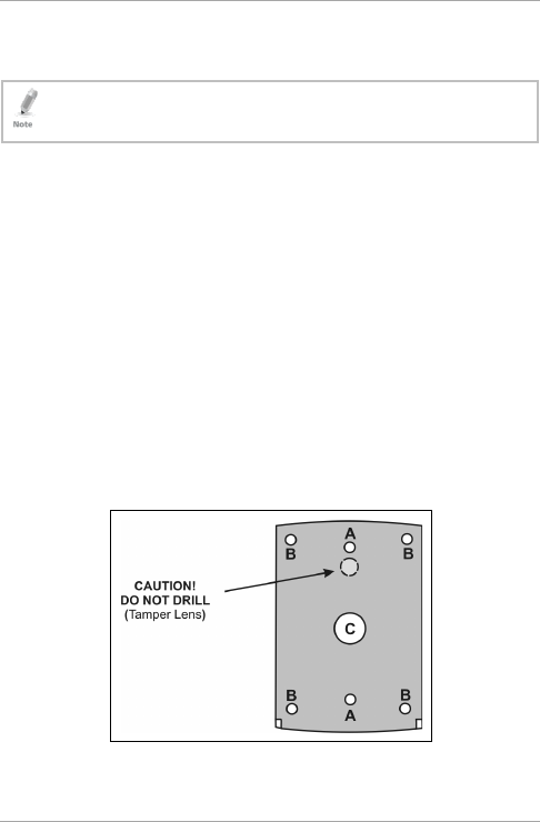
4. Depending on the type of installation, gang box or panel mount,
drill the respective holes in the rear cover (see Figure 2 for details).
For gang box mounting, drill two holes marked “A”. For flat
panel mount, drill four holes marked “B”.
Figure 2: Drilling Holes Identification
Installation
AC-Q4x Series Installation and Programming Manual 15
The central hole, marked “C” is for routing the wiring to the
controller.
5. Drill an additional 10-mm (7/16”) hole for the cable. When
installing the reader on a metallic surface, cover the inside of the
hole with a grommet or electrical tape.
6. Insert the unit’s cable wire into the cable hole and wire the unit
as described in Section 3.2.
7. Screw the back plate into the surface. Ensure the screws are the
size specified on the installation template.
The unit can also be mounted using strong epoxy glue. After
application, firmly hold the unit in place until the glue dries.
8. Carefully re-attach the front cover of the unit.
9. Secure the front cover by using the supplied security Torx screw.
A Torx security screw tool is provided to tighten the security Torx
screw.
3.2 Wiring
The controllers are provided either with a pre-wired cable or with a
screw-type terminal block:
Pre-wired Cabling Models Terminal Block Models
AC-Q41SB AC-Q41HB/HP
AC-Q42SB AC-Q42HB
AC-Q44

Installation
16 AC-Q4x Series Installation and Programming Manual
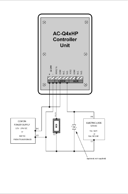
3.2.1 Pre-wired Models
These units are supplied with a 10-conductor 60-cm (24-in.) pigtail
(24-AWG cable) with exposed wires coated with solder.
To wire the controller:
1. Select the appropriate connections according to Table 1.
Table 1: Wire Color Guide
Color Description
Red V input
Black Ground
Green REX/BL
White In/Monitor
Purple Lock: Com
Gray Lock: N.O.
Brown Lock: N.C.
Blue Aux: Com
Yellow Aux: N.O.
Orange Aux: N.C.
2. Prepare the secured power supply’s cable by cutting the cable
jacket back 3.2 cm (1¼”) and strip the wire 1.3 cm (½”).
3. Splice the controller pigtail wires to the corresponding ancillary
devices and insulate each connection, including unused wires.
Refer to the wiring diagrams, depending on the desired
application:
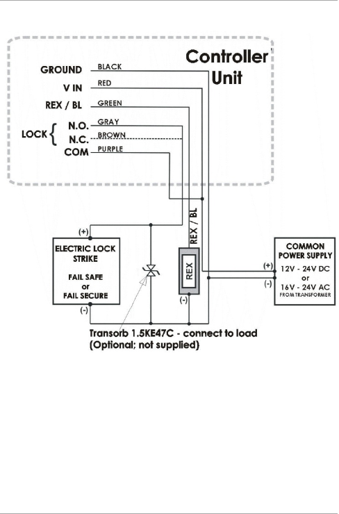
Wiring the Lock Strike Relay & REX (Figure 3)
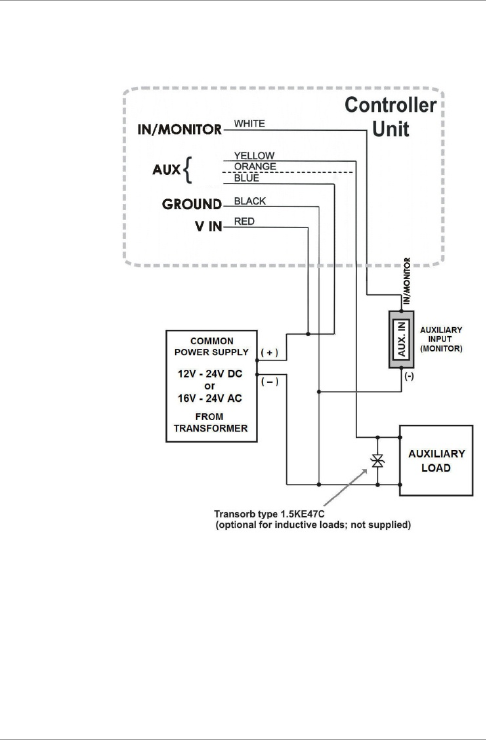
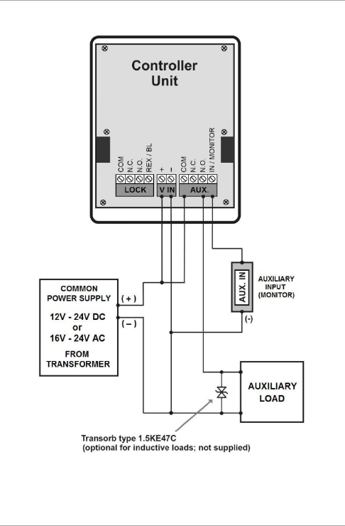
Wiring for Auxiliary Input & Output (Figure 4)
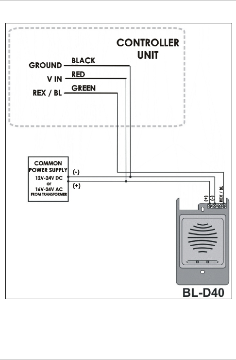
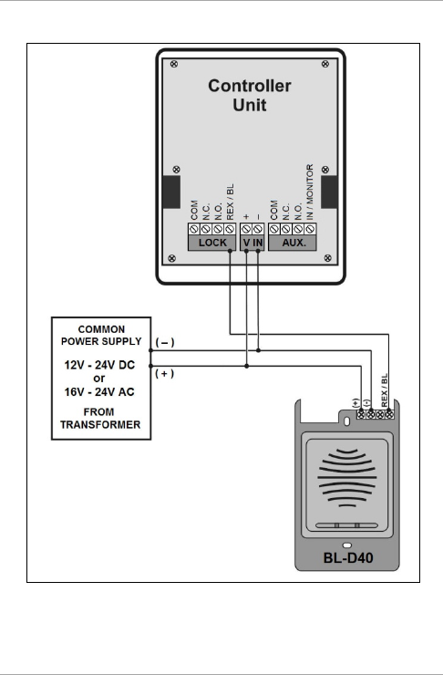
Wiring for the BL-D40 External Sounder (Figure 5)
Installation
AC-Q4x Series Installation and Programming Manual 17
Figure 3: Pre-Wired Connection for Lock Strike Relay & REX
Installation
18 AC-Q4x Series Installation and Programming Manual
Figure 4: Pre-Wired Connection for Auxiliary Input & Output
Installation
AC-Q4x Series Installation and Programming Manual 19
Figure 5: Pre-Wired Connection for the BL-D40 External Sounder
Installation
20 AC-Q4x Series Installation and Programming Manual
3.2.2 Terminal Block Models
These controllers come with removable terminal blocks that are
pushed on pins on the motherboard of the controllers.
To wire the terminal blocks:
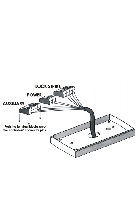
1. Route the wires or cable through the large hole in the back cover
See Figure 6. Connect the terminal blocks as shown.
2. Wire the cabling according to the following diagrams.
3. Wiring the Lock Strike Relay & REX (Figure 7)
4. Wiring for Auxiliary Input & Output (Figure 8)
5. Wiring for the BL-D40 External Sounder (Figure 9)
Figure 6: Connections to Terminal Blocks
Installation
AC-Q4x Series Installation and Programming Manual 21
Figure 7: Terminal Block Wiring of the Lock Strike Relay & REX
Installation
22 AC-Q4x Series Installation and Programming Manual
Figure 8: Terminal Block Wiring of the Auxiliary Input and Output
Installation
AC-Q4x Series Installation and Programming Manual 23
Figure 9: Terminal Block Wiring of the BL-D40 External Sounder
Operation
24 AC-Q4x Series Installation and Programming Manual
4. Operation
• In the Operation chapter, “code” refers to a PIN code or proximity
card depending on the unit you have.
• Memory slots can be a proximity card or PIN code depending on the
unit you have.
4.1 Modes of Operation
The control units have three modes of operation. These are indicated
by the color of the Mode indicator.
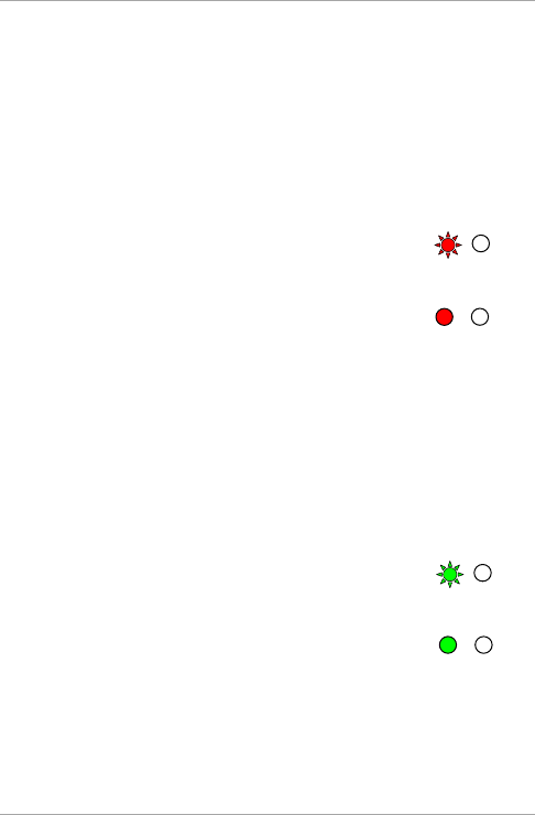
4.1.1 Normal Mode
The left LED is green.
Normal mode is the default mode. In Normal mode, the door is locked
until a valid Primary code is presented to the controller.
The controller can only be programmed in Normal mode.
4.1.2 Secure Mode
The left LED is red.
Only Secure and Master users can access the premises in Secure
mode.
A secure user must enter a primary and secondary code to gain entry.
Once the primary code has been entered, the right LED flashes green
for 10 seconds. During this time, the Secondary code must be
entered. A Master user only needs to present the code once to gain
entry.
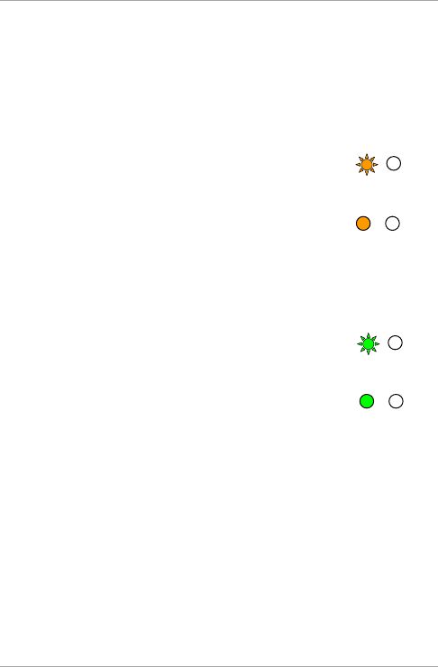
4.1.3 Bypass Mode
The left LED is orange.
In Bypass mode, access to the premises is dependent on whether the
controller's Lock Strike Relay is programmed for Fail Safe Operation or
Fail Secure Operation. When the Lock Strike relay is programmed for
Orange
Red
Green

Operation
AC-Q4x Series Installation and Programming Manual 25
Fail Secure Operation, the door is locked until the star button (*) is
pressed. When the Lock Strike relay is programmed for Fail Safe
Operation, the door is constantly unlocked.
In case of power failure, once the power is restored, the controller
returns to Normal mode for security reasons.
4.2 User Levels
AC-Q4x series access control units accept up to 500 users and provide
entry via the use of codes. Each user is allocated two memory slots:
Memory Slot 1 (primary code) and Memory Slot 2 (secondary code).
The way in which the two memory slots are programmed determines
a user’s access level and also establishes access is granted for each of
the three modes of operation.
There are three user levels:
Normal User
A Normal user only has a Primary code and is granted access only
when the controller is in its Normal or Bypass mode.
Secure User
A Secure user must have a primary and secondary code assigned,
and the two codes must not be the same. The Secure user can
gain access in any mode of operation. In Normal mode, the
secure user must use the Primary code to gain entry. In Secure
mode, the Secure user must first enter the Primary and then the
Secondary code to gain entry.
Master User
A Master user must have identical Primary and Secondary codes
assigned. The codes are entered with the same proximity card or
the same PIN. The Master user can gain access during any mode
of operation by entering the code only once.
Operation
26 AC-Q4x Series Installation and Programming Manual
4.3 Switching Operational Modes
The three modes of operation defined above can be changed through
a few steps.
4.3.1 From Normal to Secure Mode
The default factory setting for the normal/secure code is 3838.
To change from Normal to Secure mode:
1. Enter the 4-digit Normal/Secure code.
The left LED flashes red.
2. Press # to confirm the mode change.
The left LED stops flashing.
The auxiliary input of the controller can also be used to switch the
mode of operation from Secure to Normal and vice versa. If the
auxiliary input is selected, it de-activates the Norma/Secure mode code
(see Section 5.9).
4.3.2 From Secure to Normal Mode
The default factory setting for the normal/secure code is 3838.
To change from Secure to Normal mode:
1. Enter the 4-digit Normal/Secure code.
The left LED flashes green.
2. Press # to confirm the mode change.
The left LED stops flashing.
The auxiliary input of the controller can also be used to switch the
mode of operation from Secure to Normal and vice versa. If the
auxiliary input is selected, it de-activates the Norma/Secure mode code
(see Section 5.9).
Green
Green
Red
Red
Operation
AC-Q4x Series Installation and Programming Manual 27
4.3.3 From Normal to Bypass Mode
By default, there is no Normal/Bypass code. The Normal/Bypass code
must first be programmed to use this function (see Section 5.7 to
create/modify the Normal/Bypass code).
To change from Normal to Bypass mode:
1. Enter the 4-digit Normal/Bypass code.
The left LED flashes orange.
2. Press # to confirm the mode change.
The left LED stops flashing.
4.3.4 From Bypass to Normal Mode
To change from Bypass to Normal mode:
1. Enter the 4-digit Normal/Bypass code.
The left LED flashes green.
2. Press # to confirm the mode change.
The left LED stops flashing.
4.4 Auxiliary Input and Output
For optimum usability in different applications, the controller’s
auxiliary input and output can be configured in 10 different modes of
operation (see Section 5.9).
4.5 REX Button
The REX button is located within the premises and is used to open the
door from the inside. It is usually located in a convenient location,
such as next to the door or at a receptionist’s desk. The door chime in
the BL-D40 (if enabled) does not sound when the REX button is used
to open the door.
Green
Green
Orange
Orange

Operation
28 AC-Q4x Series Installation and Programming Manual
The function of the REX button depends on the Lock Strike relay,
whether it is programmed for failsafe or for fail secure operation.
Fail Secure Operation
From the moment the REX button is pressed, the door is unlocked
until the Lock Strike Release time has elapsed. After this time, the
door is locked, even if the REX button has not been released.
Failsafe Operation
From the moment the REX button is pressed, the door is unlocked
until the REX button is released. In this case, the Lock Strike relay
only begins its countdown once the REX button is released. This
feature is designed to keep the door open, when used in
conjunction with fire systems.
4.6 Tamper Feature
If the controller is forcibly opened or the controller is removed from
the wall, a tamper event is triggered. A tamper signal is sent to the
BL-D40 external sounder.
If the BL-D40 receives a tamper event signal, it activates a tamper
output and a strobe light. The Siren Time can be easily programmed
in the controller from 0 to 9 minutes.
The tamper event can activate the auxiliary output if the controller is
in Auxiliary Mode 3 (see Table 3).
4.7 Lockout Feature (Keypad/Card Tamper)
If the controller is presented with wrong codes (PIN or card)
consecutively several times, the unit goes into Lockout mode.
When a lockout occurs, the controller keypad and reader are de-
activated so no codes can be entered until the set lockout period
expires.
During Lockout mode, the left LED is Off, the right LED flashes red,
and the controller beeps every two seconds.

Operation
AC-Q4x Series Installation and Programming Manual 29
4.8 BL-D40 External Sounder
The BL-D40 external sounder is designed for indoor use only and
installed within the secured premises. The sounder can be powered by
a 12 to 24 VDC power supply or by a 16 VAC transformer. The
BL-D40 is capable of emitting four different types of audible and
visual alerts: bell, chime, siren and strobe light.
The bell sounds when the controller’s bell button is pressed.
The door chime can be programmed to sound whenever a valid
code is entered as well as for a door held open alert.
The siren can be programmed to sound when the controller is
tampered with (opened or removed from the wall). The length of
the siren can also be programmed in the controller.
The controller communicates with the BL-D40 via a Rosslare
proprietary protocol. If the BL-D40 receives an unrecognized code
over its communication line or communications between the
controller and the BL-D40 are severed, the strobe flashes repeatedly,
until the communication problem has been resolved.
Programming
30 AC-Q4x Series Installation and Programming Manual
5. Programming
• In the Programming chapter, “code” refers to a PIN code or proximity
card depending on the unit you have.
• When entering a PIN or presenting a proximity card is mentioned, the
meaning may vary between units.
Programming is done solely via the unit’s keypad-driven Programming
Menu System. To reach the Programming Menu System, the
controller must first be placed into Programming Mode (see Section
5.1).
During the manufacturing process, certain codes and settings are pre-
programmed. These settings are the called default factory settings.
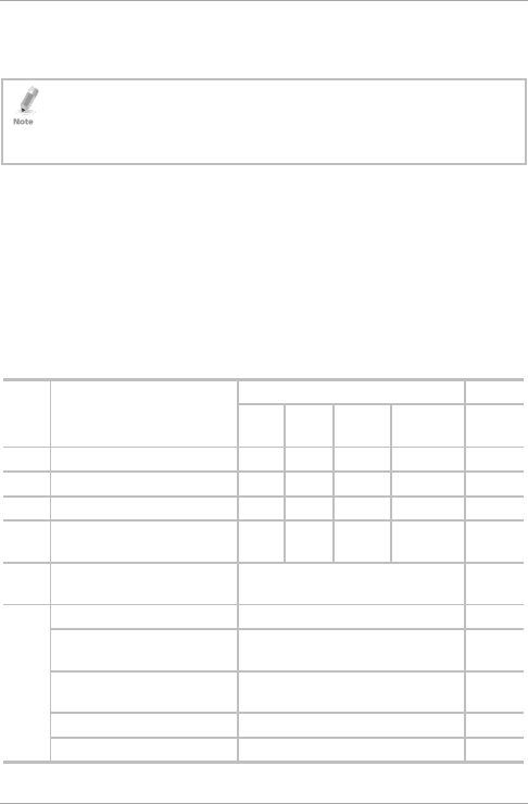
Table 2 shows all the programming menus, with default factory codes
and settings.
Table 2: Programming Menus
Menu
No.
Description Default Section
4
Digits
5
Digits
6
Digits
4-8 Digits
1 Change Open code 2580 25802 258025 25802580 5.3
2 Change Auxiliary code 0852 08520 085208 08520852 5.4
3 Change Program code 1234 12341 123412 12341234 5.5
4 Change Normal/Secure
code
3838 38383 383838 38383838 5.6
5 Change Normal/Bypass
code
NA 5.7
6 Change Door Release time 0004 5.8
Define auxiliary
inputs/outputs
2004 5.9
Enable or disable keypad
heater
3000 5.10
Set Lockout Feature 4000 5.11
Backlight and LED Behavior 5100 5.12
Programming
AC-Q4x Series Installation and Programming Manual 31
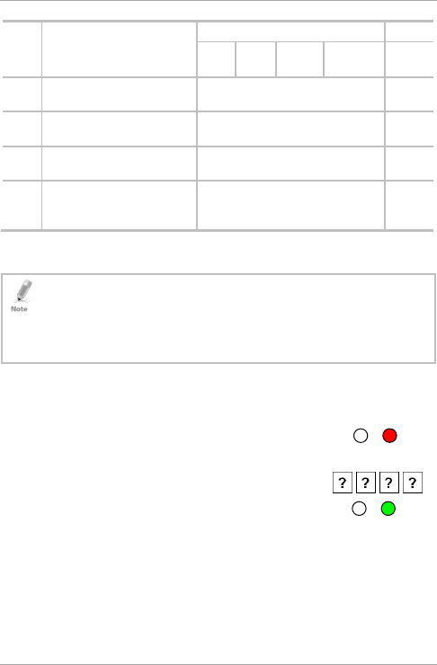
Menu
No.
Description Default Section
4
Digits
5
Digits
6
Digits
4-8 Digits
7 Enroll proximity cards, PIN
or both
NA 5.13
8 Delete proximity cards or
PIN
NA 5.14
9 Code assignment with
strike/auxiliary
NA 5.15
0 Return to factory
defaults/Change PIN code
Length
NA 5.16
5.1 Entering the Programming Mode
• The controller must be in Normal mode to enter the programming
mode.
• The factory default 4-digit programming code is 1234.
• If a Programming code is not entered within 5 seconds, the controller
returns to Normal mode.
To enter Programming mode:
1. Press # twice.
The left LED turns off and the right LED turns
red.
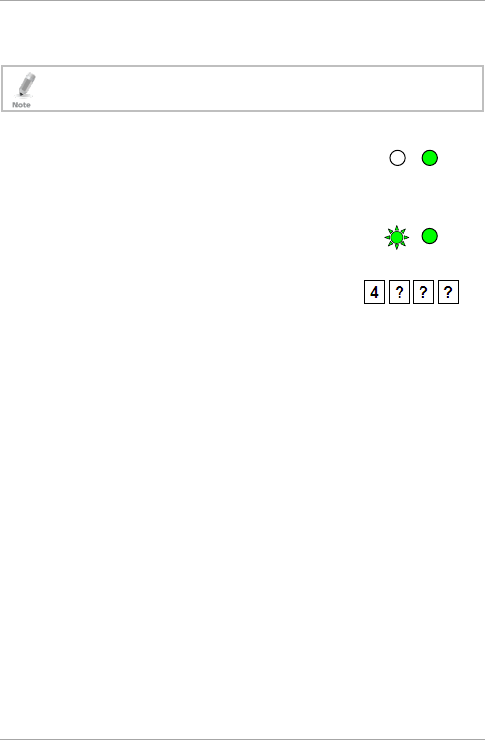
2. Enter your 4-digit Programming code.
The right LED turns green.
Red
Programming
32 AC-Q4x Series Installation and Programming Manual
5.2 Exiting the Programming Mode
• Wrong entries may reset the controller back to Normal mode.
• If no key is pressed for 1 minute, while in programming mode, the
controller exits Programming mode and returns to Normal mode.
To exit Programming mode:
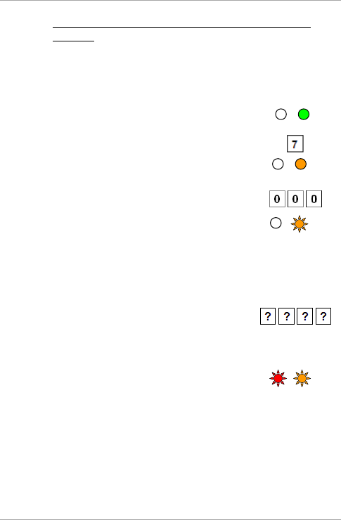
1. Press # twice to exit Programming mode at any time.
You hear 3 beeps.
The left LED turns green and the right LED
turns off.
Wrong entries reset the controller back to Normal mode.
While in Programming mode, if no key is pressed for one minute,
the unit exits Programming mode and returns to Normal mode.
5.3 Changing the Open Code
The Open code is mainly used as a method to quickly test the Lock
Strike relay during installation.
For security reasons, when the first user is added to the controller or
the Auxiliary code is changed, the default Open code is automatically
deleted; non-default codes are not be erased automatically.
• Open code does not function in Secure mode.
• For wrong entries, you hear a long beep and the controller returns to
Normal mode.
• Code 0000 erases and deactivate the open code.
• The factory 4-digit default setting for the open code is 2580.
Green
Programming
AC-Q4x Series Installation and Programming Manual 33
To change the Open code:
1. Enter Programming mode.
2. Press 1 to enter Menu 1.
The left LED turns red.
3. Enter the new 4-digit Open code.
You hear three beeps.
The system returns to Normal mode.
5.4 Changing the Auxiliary Code
The Auxiliary code is mainly used as a method to quickly test the
Auxiliary relay during installation.
For security reasons, when the first user is added to the controller or
the open code is changed, the default auxiliary code is automatically
deleted; non-default codes are not be erased automatically.
• Auxiliary code does not function in Secure mode.
• Auxiliary code only works when the Auxiliary mode is 0, 1, 8 or 9.
• Wrong entries return the controller to Normal mode.
• Code 0000 erases and deactivates the auxiliary code.
• The default 4-digit factory setting for the auxiliary code is 0852.
To change the Auxiliary code:
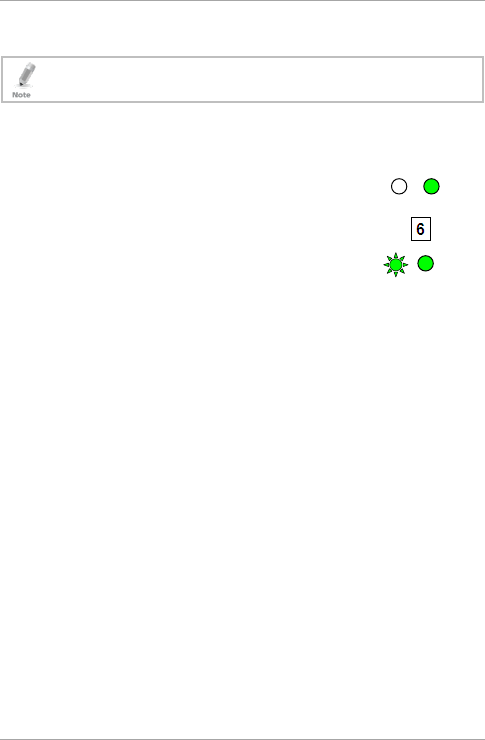
1. Enter Programming mode.
2. Press 2 to enter Menu 2.
The left LED turns orange.
Orange Green
Green
Green
Red Green
Green
Programming
34 AC-Q4x Series Installation and Programming Manual
3. Enter the new 4-digit Auxiliary code.
You hear three beeps.
The system returns to Normal mode.
5.5 Changing the Programming Code
• The Programming code cannot be erased; the code 0000 is invalid
and does not erase the Programming code.
• The factory default 4-digit Programming code is 1234.
To change the Programming code:
1. Enter Programming mode.
2. Press 3 to enter Menu 3.
The left LED turns green.
3. Enter the new 4-digit Programming code.
You hear three beeps.
The system returns to Normal mode.
5.6 Changing the Normal/Secure Code
• When the Auxiliary mode is 1, 2, 3 or 4, the auxiliary input takes
priority over the Normal/Secure code.
• Code 0000 erases and deactivates the Normal/Secure code.
To change the Normal/Secure code:
1. Enter Programming mode.
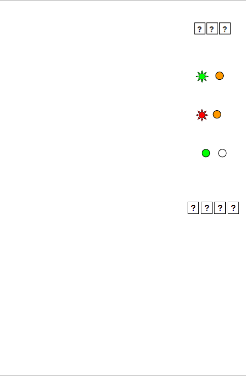
2. Press 4 to enter Menu 4.
The left LED flashes red.
Green Green
Red
Green
Green
Green
Green
Green
Programming
AC-Q4x Series Installation and Programming Manual 35
3. Enter the new 4-digit Normal/Secure code.
You hear three beeps.
The system returns to Normal mode.
5.7 Changing the Normal/Bypass Code
The Normal/Bypass code is also used to turn the door chime off and
on. Chime only functions with the BL-D40 external sounder.
• The chime is only heard when the Lock Strike relay is activated by a
valid code entry.
• Code 0000 erases and deactivates the Normal/Bypass code.
To change the Normal/Bypass code:
1. Enter Programming mode.
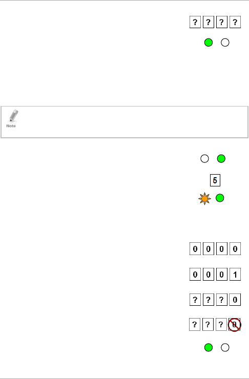
2. Press 5 to enter Menu 5.
The left LED flashes orange.
3. There are four different ways to program the Normal/Bypass code
and door chime:
Disable both Bypass code and the door chime.
Enter the code 0000.
Disable Bypass code and enable the door
chime. Enter the code 0001.
Enable Bypass code and disable the door
chime. Enter any code ending with 0.
Enable Bypass code and enable the door
chime. Enter a code not ending with 0.
You hear three beeps.
The system returns to Normal mode.
Green
Orange
Green
Green
Green
Programming
36 AC-Q4x Series Installation and Programming Manual
5.8 Setting Fail Safe/Secure Operation, Tamper
Siren and Lock Strike Release Time
The default value is 0004, which corresponds to Fail Secure
operation, no siren, and 4-seconds Lock Strike release time.
To set the Fail Safe/Secure Operation, Tamper Siren and Lock
Strike Release Time:
1. Enter Programming mode.
2. Press 6 to enter Menu 6.
The left LED flashes green.
3. Construct a code using the following
instructions:
First digit
For Fail Secure Operation, the first digit should be 0.
For Fail Safe Operation the first digit should be 1.
Second digit
Siren Time in minutes (1–9, 0 – disabled)
Third and fourth digits
Enter the number of seconds (from 1 to 99) that you want
the Lock Strike to be released.
For example, 0312 means a Fail Secure Operation consisting of a
3-minute siren and a 12-second Lock Strike release time.
You hear three beeps.
The system returns to Normal mode.
Green
Green Green
Green
Programming
AC-Q4x Series Installation and Programming Manual 37
5.9 Setting Auxiliary Modes
The default auxiliary setting is 2004.
Auxiliary Relay activation is subject to the user’s Auxiliary
code assignment (excluding Shunt, which is activated by all
users). For more details, see Section 5.15.
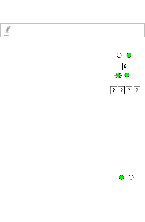
To set Auxiliary modes:
1. Enter Programming mode.
2. Press 6 to enter Menu 6.
The left LED flashes green.
3. Construct a code using the following
instructions:
Second digit (Auxiliary Mode)
In addition to the Lock Strike Relay and Lock Strike REX, the
unit features an Auxiliary Input. The Auxiliary mode defines
the function of the Auxiliary Input.
Third and fourth digits (Auxiliary Setting)
Each of the Auxiliary modes has a 2-digit setting that affects
how the Auxiliary mode functions (Table 3).
You hear three beeps.
The system returns to Normal mode.
Green
Green Green
Green

Programming
38 AC-Q4x Series Installation and Programming Manual
Table 3: Quick Reference Guide for Auxiliary Mode Setting
Auxiliary
Mode
Auxiliary
Input
Function
Auxiliary Output
Activated by
Auxiliary
Relay
Auxiliary Settings
(in seconds)
0 AUX REX Valid code or AUX
REX
N.O. 01 to 99 Aux. Relay
Release Time
00 Aux. relay toggle
1 Normal/Secure
switch
Valid code N.O. 01 to 99 Aux. Relay
Release Time
00 Aux. relay toggle
2 Normal/Secure
switch
Star button (*) N.O. 01 to 99 Aux. Relay
Release Time
00 Aux. relay toggle
3 Normal/Secure
switch
Tamper event N.C. 01 to 99 Aux. Relay
Release Time
00 Aux. relay tamper
activated
4 Normal/Secure
switch
Direct shunt N.O. 01 to 99 Shunt time
5 Door Monitor Shunt N.C. 01 to 99 maximum
Shunt time
6 Door Monitor Forced door N.C. 01 to 99 Forced delay
7 Door Monitor Door ajar N.C. 01 to 99 Ajar delay
8 LED control –
Green
Valid code N.O. 01 to 99 Aux. Relay
Release time
00 Aux. relay toggle
9 LED control –
Red
Valid code N.O. 01 to 99 Aux. Relay
Release time
00 Aux. relay toggle

Programming
AC-Q4x Series Installation and Programming Manual 39
The following subsections describe each Auxiliary mode.
5.9.1 Auxiliary Mode 0
Auxiliary input function: Activates the auxiliary output
Auxiliary output activated by: Valid user code, Auxiliary code,
Auxiliary input
For example, in Auxiliary Mode 0, the controller can function as a
2-door controller. The auxiliary relay is to be attached to the lock on
the second door. The auxiliary setting defines the Door Open time for
the second door. The auxiliary input is to be attached to the REX
button for the second door. Door Monitor input feature for the
second door is not enabled when using this mode.
5.9.2 Auxiliary Mode 1
Auxiliary input function: Toggles Normal/Secure modes
Auxiliary output activated by: Valid user code, Auxiliary code
For example, in Auxiliary Mode 1, the controller can function as a
2-door controller. The auxiliary relay is to be attached to the lock on
the second door. REX feature for the second door is not enabled
when using this mode.
The auxiliary setting defines the Door Open time for the second door.
The auxiliary input can switch the mode of operation of the controller
between Normal and Secure mode. By connecting a switch timer or
alarm system output to the auxiliary input, the controller can be
automatically switched from Normal mode (during office hours) to
Secure mode (after office hours).
5.9.3 Auxiliary Mode 2
Auxiliary input function: Toggles Normal/Secure modes
Auxiliary output activated by: Star Button (*)
For example, in Auxiliary Mode 2, the auxiliary relay can function as a
general purpose time switch that can be activated when * is pressed.
The auxiliary setting establishes for how long the auxiliary relay is to
be activated. The auxiliary input can switch the mode of operation of
the controller between Normal and Secure mode. By connecting a

Programming
40 AC-Q4x Series Installation and Programming Manual
switch timer or alarm system output to the auxiliary input, the
controller can be automatically switched from Normal mode (during
office hours) to Secure mode (after office hours).
5.9.4 Auxiliary Mode 3
Auxiliary input function: Toggles Normal/Secure modes
Auxiliary output activated by: Alarms
For example, in Auxiliary Mode 3, the auxiliary output is activated if
the controller is tampered; that is, if the case is forcibly opened or
removed from the wall. The auxiliary input can switch the mode of
operation of the controller between Normal and Secure mode. By
connecting a switch timer or alarm system output to the auxiliary
input, the controller can be automatically switched from Normal
mode (during office hours) to Secure mode (after office hours).
5.9.5 Auxiliary Mode 4
Auxiliary input function: Toggles Normal/Secure modes
Auxiliary output activated by: direct shunt (explanation below)
For example, in Auxiliary Mode 4, the controller is capable of
bypassing an alarm zone by shunting an alarm system’s door sensor.
The auxiliary output is to be wired in parallel to the door sensor
output. When in use, the auxiliary output is normally open and the
door sensor functions normally. When a valid code is entered, the
auxiliary relay shunts the door sensor for the duration of the Shunt
time, as defined by the auxiliary setting. If the door is left open longer
than the Shunt time, an alarm is triggered.
5.9.6 Auxiliary Mode 5
Auxiliary input function: Door Monitor
Auxiliary output activated by: Shunt (explanation below)
For example, in Auxiliary Mode 5, the controller is capable of shunting
an alarm system. In this mode, the auxiliary input is to be wired to the
magnetic contact switch on the door. The auxiliary relay is wired to
the alarm system. Without a valid code entered, the auxiliary relay
matches the condition of the magnetic contact switch; if the door

Programming
AC-Q4x Series Installation and Programming Manual 41
opens, the auxiliary relay opens; if the door closes, the auxiliary relay
closes. When a valid code is entered, a countdown for maximum
Shunt time, as defined by the auxiliary setting, begins; if the door is
not closed before the maximum Shunt time, the alarm is triggered.
5.9.7 Auxiliary Mode 6
Auxiliary input function: Door Monitor
Auxiliary output activated by: Forced entry
For example, in Auxiliary Mode 6, the controller can trigger the
auxiliary relay if the door has been forced. If the Siren Settings is
enabled, the siren is activated.
In this mode, the auxiliary input functions as a door monitor switch
and is wired to the magnetic contact switch on the door. The auxiliary
relay is to be wired to the alarm system. If the door is forced open,
the controller waits for the period of the Forced Door Delay time to
elapse and then it activates the auxiliary relay. The auxiliary setting
sets the forced door delay period.
5.9.8 Auxiliary Mode 7
Auxiliary input function: Door Monitor
Auxiliary output activated by: Door Ajar (door held open)
For example, in Auxiliary Mode 7, the controller can trigger the
auxiliary relay, if it detects that the door has been held open (ajar) too
long. In this mode the auxiliary input functions as a door monitor
switch and is wired to the magnetic contact switch on the door. The
auxiliary relay is to be wired to the alarm system. If the door is
opened, the controller waits for the Door Ajar Delay time to elapse
and if the door does not close prior to the end of this period, the
controller activates the auxiliary relay. The auxiliary setting defines the
Door Ajar time.
If the BL-D40 External Sounder is connected in the system and a door-
ajar event occurs, the BL-D40 chimes every few seconds for 1 minute
or until the door is closed.
Programming
42 AC-Q4x Series Installation and Programming Manual
5.9.9 Auxiliary Mode 8
Auxiliary input function: Green LED control
Auxiliary output activated by: Valid user code, Auxiliary code
For example, in Auxiliary Mode 8, the controller can function as a
2-door controller and also provide indicator functionality control. The
auxiliary relay is connected to the lock on the second door. The
auxiliary setting defines the Door Open time for the second door. The
auxiliary input is used to control the Door indicator. If the auxiliary
input is open, the indicator flashes green; if the auxiliary input is
closed, the Door indicator flashes red.
This mode takes control of the Door indicator LED.
The indicator LED is not lit when:
• A valid code is entered
• While in Secure mode, when waiting for a secondary code
5.9.10 Auxiliary Mode 9
Auxiliary input function: Red LED control
Auxiliary output activated by: Valid user code, Auxiliary code
For example, in Auxiliary Mode 9, the controller can function as a
2-door controller and also provide indicator functionality control. The
auxiliary relay is connected to the lock on the second door. The
auxiliary setting defines the Door Open time for the second door. The
auxiliary input is used to control the indicator. If the auxiliary input is
open, the Door indicator flashes red; if the auxiliary input is closed,
the Door indicator flashes green.
This mode takes control of the Door indicator LED.
The indicator LED is not lit when:
• A valid code is entered
• While in Secure mode, when waiting for a secondary code
Programming
AC-Q4x Series Installation and Programming Manual 43
5.10 Keypad Heater Operation
This section is not applicable for AC-Q44 (without keypad
heater).
The controllers contain a built-in keypad heater. Once the heater
circuitry is activated, the heater turns on when the ambient
temperature drops to 4±1°C and remains on until the keypad
temperature rises to 7(+2 or -1)°C.
When the heater is on, the controller can operate down to an
ambient temperature of -20°C. When the heater is disabled, the
lowest operating temperature is 0°C.
The default setting for the keypad heater is disabled state (3000).
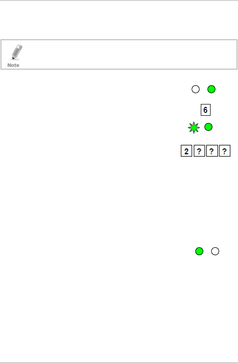
To define the keypad heater operation:
1. Enter Programming mode.
2. Press 6 to enter Menu 6.
3. The Mode indicator flashes green.
4. Construct a code using the following
instructions:
To disable the heater, the fourth digit is set to 0.
To enable the heater, the fourth digit is set to 1.
5.11 Setting the Lockout Feature
If the controller is presented with wrong codes (PIN or card)
consecutively several times, the unit goes into Lockout mode.
When a lockout occurs, the controller keypad and reader are locked
so no codes can be entered until the set lockout period expires.
During Lockout, the left LED is Off, the right LED flashes red, and the
Green Green
Green
Programming
44 AC-Q4x Series Installation and Programming Manual
controller beeps every two seconds. The default setting for the
Lockout Feature is 4000 (Lockout Disabled).
Using the lockout feature is highly recommended, especially
when selecting to use short PIN code length (4 or 5 digits).
To define the Lockout feature:
1. Enter Programming mode.
2. Press 6 to enter Menu 6.
The Mode indicator flashes green.
3. Construct a code using the following
instructions:
Second digit
Set the number of wrong code attempts, which causes a
Lockout between 0 and 9 attempts.
Third and fourth digits
Sets the Duration of the lockout, between 00 and 99; the
value is multiplied by ten, resulting in 0 to 990 seconds.
Mode Door
Green
Mode Door
Green
Green
Programming
AC-Q4x Series Installation and Programming Manual 45
5.12 Setting the Backlight Behavior
This section is applicable for AC-Q4xHB/SB models only
(backlight).
The controller allows you to define the way the unit’s backlight
works.
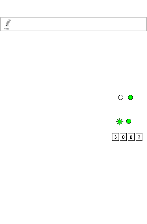
To set the backlight behavior:
1. Enter Programming mode.
2. Press 6 to enter Menu 6.
The left LED flashes green.
3. Enter one of the following codes:
5000 – Backlight off
5100 – Backlight on (default)
5200 – Backlight is off, activates for 10 seconds when a key is
pressed, after which it dims until off
5300 – Backlight is dimmed, activates for 10 seconds when a
key is pressed, after which it returns to a dimmed level
5.13 Enrolling Primary and Secondary Codes
5.13.1 Primary Codes Definition
Primary codes can only be enrolled to an empty user slot, a slot
with no existing Primary code in the controller’s memory.
A Primary code must be unique; for instance, one user’s primary
code may not be the same as that of another user.
Primary codes cannot be the same as system codes, such as: the
Normal/Secure code or the Open code.
Users possessing a Primary code can gain entry during Normal
and Bypass modes.
Green Green

Programming
46 AC-Q4x Series Installation and Programming Manual
5.13.2 Secondary Codes Definition
Secondary codes can only be enrolled to a user slot that already
includes a primary code.
A secondary code need not be unique; for instance, one user’s
Secondary code may be the same as that of another user.
Secondary codes cannot be the same as any system codes, such
as: the Normal/Secure code or the open code.
Users possessing secondary codes can gain entry in any mode of
operation.
A secondary code can be the same as the primary code of any
user.
5.13.3 Enrolling Methods
There are two methods used to enroll primary and secondary codes:
the standard method and the code search method.
The Standard Method is used when the user slot number, for the
user you wish to program, is known. You can program both
primary and secondary codes using this method.
The Code Search Method is mainly used when enrolling a
secondary code and the user’s slot code is unknown. The code
search method functions only if a user’s primary code is already
enrolled and the secondary code is not.
5.13.3.1 Enrolling Primary and Secondary Codes using the
Standard Method
To enroll Primary and Secondary codes using the Standard
method:
1. Enter Programming mode.
2. Press 7 to enter Menu 7.
The right LED turns orange.
Orange
Green
Programming
AC-Q4x Series Installation and Programming Manual 47
3. Enter the 3-digit user slot number between
001and 500 for the slot to which you wish to
enroll a Primary or Secondary code.
For example, User Slot 003 represents User #3.
If the selected slot has no Primary code, the
left LED flashes green, indicating that the
controller is ready to accept a Primary code.
If the selected slot already has a Primary code
but no Secondary code, the left LED flashes
red, indicating that the controller is ready to
accept a Secondary code.
If the selected slot already has a Primary and
Secondary code, you hear a long beep and the
controller returns to Normal mode.
4. Perform one of the following:
Enter the PIN code that you want to assign
as the Primary or Secondary code for this
slot number.
Present your user card that you want to assign as the Primary
or Secondary code for this slot number.
If the PIN or user card presented is valid, the left LED stops
flashing and the controller is ready for you to enter the next
3-digit slot number (refer to Step
3) for the slot to which you
want to assign a code.
5. Do one of the following:
Press # to move to the next available user slot number.
Enter another 3-digit user slot number.
If you do not wish to continue enrolling codes, press # twice
and the controller returns to Normal mode.
Green
Red Orange
Gree
Orange
Programming
48 AC-Q4x Series Installation and Programming Manual
5.13.3.2 Enrolling Secondary Codes using the Code Search
Method
The code search method enables to quickly enroll a secondary code
for a user whose primary code is known and whose slot number is
unknown.
To enroll secondary codes using the Code Search method:
1. Enter Programming mode.
2. Press 7 to enter Menu 7.
The right LED turns orange.
3. Enter 000 as the 3-digit user slot number.
The right LED flashes orange.
The controller is now waiting for the Primary code of the user to
whom you want to add a Secondary code.
4. Perform one of the following:
Enter the PIN code belonging to the user for
whom you wish to add a Secondary code.
Present the user card belonging to the user for whom you wish to
add a Secondary code.
The left LED flashes red.
If the Primary code entered is not valid, you hear a long beep and
the unit continues to wait for a valid Primary code.
Red Orange
Orange
Orange
Green
Programming
AC-Q4x Series Installation and Programming Manual 49
5. Perform one of the following:
Enter the PIN code to be used as the
Secondary code.
Present the user card to be used as the Secondary code.
If the Secondary code is valid, the controller beeps three times
and returns to Normal mode.
If the Secondary code is invalid, the controller sounds a long
beep, and the unit continues to wait for a valid Secondary code
to be entered.
5.14 Deleting Primary and Secondary Codes
There are two methods to delete primary and secondary codes: a
standard method and a search method. When deleting a user slot,
both the primary code and the secondary code are erased.
It is recommended that a record be kept of added and deleted
users. This makes it easier to keep track of user slots’ status
(empty or not).
5.14.1 Deleting Primary and Secondary Codes using the
Standard Method
To delete the Primary and Secondary codes using the Standard
Method:
1. Enter Programming mode.
2. Press 8 to enter Menu 8.
The left LED turns red and the right LED turns
orange.
3. Enter the 3-digit User Slot code you wish to
delete.
Red Orange
Green
Programming
50 AC-Q4x Series Installation and Programming Manual
The left LED flashes red indicating the
controller is waiting for the Programming code
to confirm the deletion.
If the user slot is empty, you hear a long beep and the unit
returns to Normal mode.
4. Enter your 4-digit Programming code to
confirm the deletion.
If the Programming code is valid, three beeps are heard and the
controller returns to Normal mode.
If the Programming code is invalid, a long beep is heard and the
controller returns to Normal mode.
5.14.2 Deleting Primary and Secondary Codes using the
Code Search Method
To delete the Primary and Secondary codes using the Code
Search Method:
1. Enter Programming mode.
2. Press 8 to enter Menu 8.
The left LED turns red and the right LED turns
orange.
3. Enter 000 as the 3-digit user slot number.
The right LED flashes orange.
The controller is now waiting for the Primary code of the user you
want to delete.
Red Orange
Red Orange
Green
Red Orange
Programming
AC-Q4x Series Installation and Programming Manual 51
4. Perform one of the following:
Enter the PIN code of the Primary code
belonging to the user you want to delete.
Present the user card of the Primary code belonging to the
user you want to delete.
The left LED flashes red.
5. Enter your 4-digit Programming code to confirm the deletion.
If the Programming code is valid, you hear three beeps and the
unit returns to Normal mode.
If the Programming code is invalid, you hear a long beep and the
unit returns to Normal mode.
5.15 Relay Codes Assignment
When a primary code is enrolled for any user, the user is authorized
to activate the Lock Strike relay. However, different user codes may
be set to operate the auxiliary relay instead or operate both the Lock
strike and auxiliary relay. Assignment of such codes is achievable for
any valid user code entered in the controller.
There are two methods to assign relay codes to users: a standard
method and a search method.
5.15.1 Relay Code Assignment using Standard Method
To assign the relay code using Standard method:
1. Enter Programming mode.
2. Press 9 to enter Menu 9.
The left LED turns green and the right LED
turns orange.
3. Enter the 3-digit user slot for code assignment.
Green Orange
Green
Red Orange
Programming
52 AC-Q4x Series Installation and Programming Manual
The left LED flashes green.
4. Enter the assignment digit for the current user slot:
1 activates the Lock Strike relay only default
2 activates the Auxiliary relay only
3 activates the Lock Strike and Auxiliary relays
If the assignment code is valid, the left LED stops flashing.
The controller is now waiting for another slot number.
5. Do one of the following:
Press # to move to the next available user slot number.
Enter another 3-digit user slot number.
If you do not wish to continue enrolling codes, press # twice and
the controller returns to Normal mode.
5.15.2 Relay Code Assignment using Search Method
To assign the relay code using Search method:
1. Enter Programming mode.
2. Press 9 to enter Menu 9.
The left LED turns green and the right LED
turns orange.
3. Enter 000 for user slot access.
The right LED flashes orange.
Green
Orange
Green Orange
Green
Green
Orange

Programming
AC-Q4x Series Installation and Programming Manual 53
4. Do one of the following:
Enter the PIN code of the Primary code
belonging to the user you want to delete.
Present the user card of the Primary code belonging to the
user you want to delete.
The left LED flashes green.
5. Enter the assignment digit for the current user slot:
1 activates the Lock Strike relay only default
2 activates the Auxiliary relay only
3 activates the Lock Strike and Auxiliary relays
If the assignment digit is
valid
, three beeps are heard and the
controller returns to Normal mode.
If the assignment digit is
invalid
, a long beep sounds and the
controller waits for another assignment digit to be entered.
Green
Orange
Programming
54 AC-Q4x Series Installation and Programming Manual
5.16 Changing PIN Code Length/Factory Default
Settings
You must be very careful before using this command! Changing
the PIN code length also erases the entire memory contents,
including all user and special codes, and returns all codes to
their factory default settings.
To change PIN code length:
1. Enter Programming mode.
2. Select the desired PIN code length as follows:
00 – Returns to factory defaults and sets a 4-digit code
05 – Returns to factory defaults and sets a 5-digit code
06 – Returns to factory defaults and sets a 6-digit code
08 – Returns to factory defaults and sets a 4-8 digit code
When choosing the 4–8 option, please note that you should
either enter zeros before the code, or press pound at the end
(for example if your code is 12345, enter either 00012345 or
12345#).
Both LEDs flash red.
3. Enter your 4-digit Programming code.
If the Programming code is valid, all memory is erased. You hear
three beeps and the controller returns to Normal mode.
If the Programming code is invalid, you hear a long beep and the
controller returns to Normal mode without erasing the memory
contents.
Red Red
Green
Programming
AC-Q4x Series Installation and Programming Manual 55
5.17 Replacing a Programming Code
The controller must be in Normal mode for the procedure to
work. Ensure that the Mode indicator is green before
proceeding.
To replace a Programming code:
1. Remove power from the controller.
2. Press and hold the REX button.
3. Apply power to the unit with the REX button pressed.
4. Release the REX button.
5. You now have 15 seconds to program a new programming code
into the unit using the initial default code before the controller
reverts to the existing code.
The deafult code depends on the PIN length selected (see Table
2).
5.18 Replacing a Normal/Secure Code
The controller must be in its Secure mode for the procedure to
work. Ensure that the Mode indicator is red before proceeding.
To replace a Normal/Secure code:
1. Remove power from the controller.
2. Press and hold the REX button.
3. Apply power to the unit with the REX button pressed.
4. Release the REX button.
5. You now have 15 seconds to use the Normal/Secure code to
return to the Normal mode.
6. Once in Normal mode, enter Programming mode to program a
new Normal/Secure code.
The deafult code depends on the PIN length selected (see Table
2).

56 AC-Q4x Series Installation and Programming Manual
A. Limited Warranty
The full ROSSLARE Limited Warranty Statement is available in the
Quick Links section on the ROSSLARE website at
www.rosslaresecurity.com.
Rosslare considers any use of this product as agreement to the
Warranty Terms even if you do not review them.
This device complies with part 15 of the FCC Rules.
Operation is subject to the following two conditions:
(1) This device may not cause harmful interference, and
(2) This device must accept any interference received, including interference that may cause undesired
operation.
Note: This equipment has been tested and found to comply with the limits for a Clas
s B digital
device, pursuant to Part 15 of the FCC Rules. These limits are designed to provide reasonable
protection against harmful interference in a residential installation. This equipment generates,
uses and can radiate radio frequency energy and, if not installed and used in accordance with
the instructions, may cause harmful interference to radio communications.
However, there is no guarantee that interference will not occur in a particular installation. If this
equipment does cause harmful interference to radio or television reception, which can be
determined by turning the equipment off and on, the user is encouraged to try to correct the
interference by one or more of the following measures:
NOTE: This equipment has been tested and found to comply with the limits for a Class B digital device,
pursuant to Part 15 of the FCC Rules. These limits are designed to provide reasonable protection against harmful
interference in a residential installation. This equipment generates uses and can radiate radio frequency energy and,
if not installed and used in accordance with the instructions, may cause harmful interference to radio communications.
However, there is no guarantee that interference will not occur in a particular installation.
If this equipment does cause harmful interference to radio or television reception, which can be determined by turning
the equipment off and on, the user is encouraged to try to correct the interference by one or more
of the following measures:
---Reorient or relocate the receiving antenna.
---Increase the separation between the equipment and receiver.
---Connect the equipment into an outlet on a circuit different from that to which the receiver is connected.
---Consult the dealer or an experienced radio/TV technician for help.
WARNING: Changes or modifications not expressly approved by the party responsible for compliance
could void the user's authority to operate the equipment.
AC-Q4x Series
0706-0960121+05
Asia Pacific, Middle
East, Africa
Rosslare Enterprises Ltd.
Kowloon Bay, Hong Kong
Tel: +852 2795-5630
Fax: +852 2795-1508
support.apac@rosslaresecurity.com
United States and
Canada
Rosslare Security Products, Inc.
Southlake, TX, USA
Toll Free: +1-866-632-1101
Local: +1-817-305-0006
Fax: +1-817-305-0069
support.na@rosslaresecurity.com
Europe
Rosslare Israel Ltd.
Rosh HaAyin, Israel
Tel: +972 3 938-6838
Fax: +972 3 938-6830
support.eu@rosslaresecurity.com
Latin America
Rosslare Latin America
Buenos Aires, Argentina
Tel: +54-11-4001-3104
support.la@rosslaresecurity.com
China
Rosslare Electronics (Shenzhen) Ltd.
Shenzhen, China
Tel: +86 755 8610 6842
Fax: +86 755 8610 6101
support.cn@rosslaresecurity.com
India
Rosslare Electronics India Pvt Ltd.
Tel/Fax: +91 20 40147830
Mobile: +91 9975768824
sales.in@rosslaresecurity.com
CERT
ISO 9001
ISO 14001