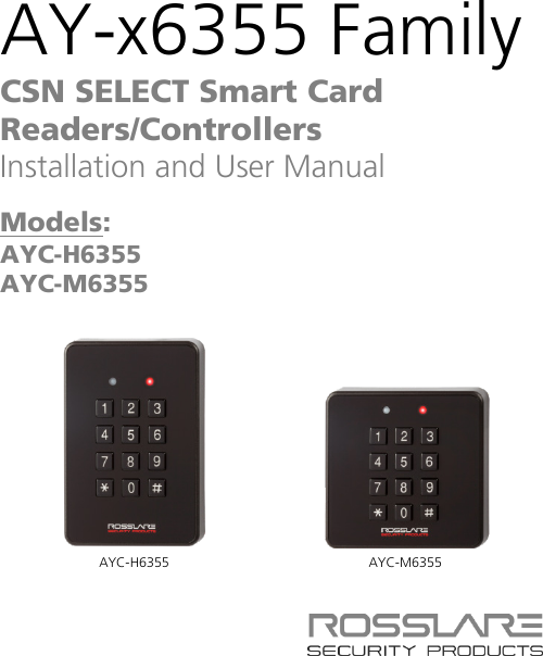
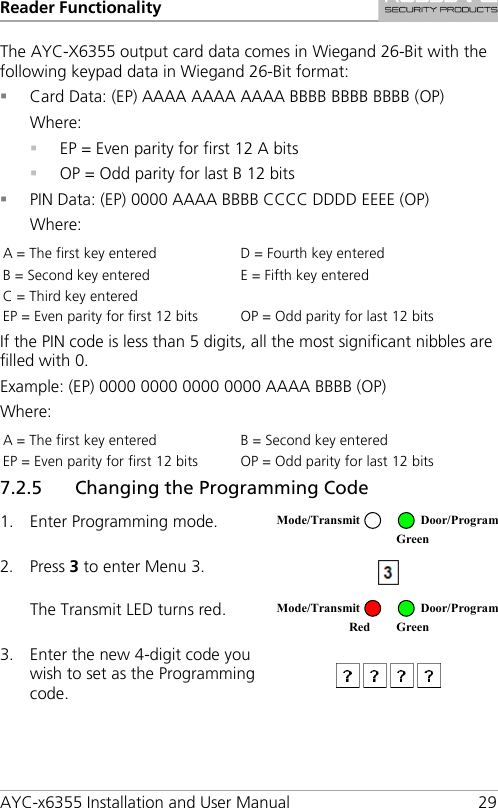
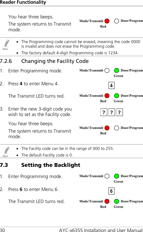
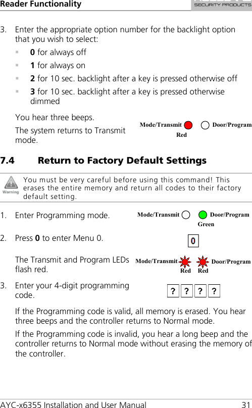
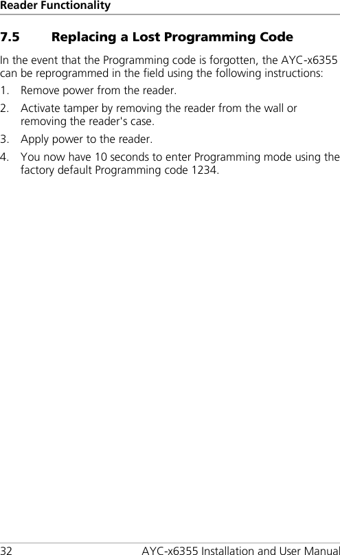
Rosslare AYCX6X55 Smart Card CSN Reader User Manual AYC x6355 Installation and
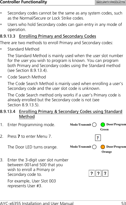
Rosslare Enterprises Ltd Smart Card CSN Reader AYC x6355 Installation and
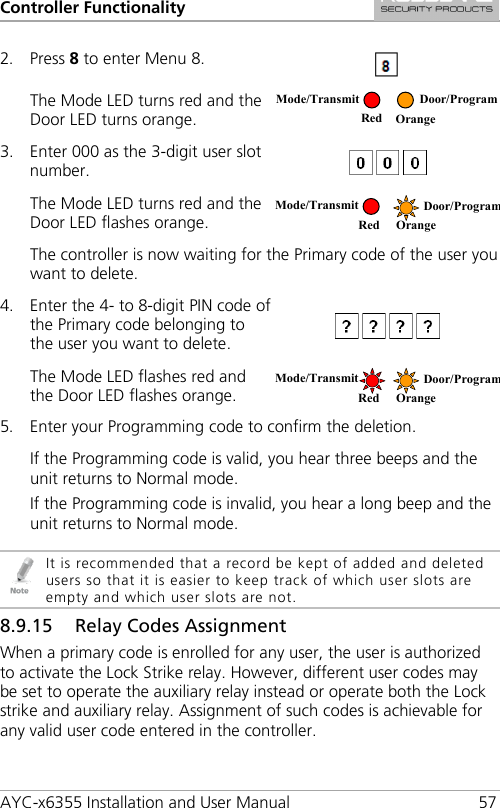
UserManual.wiki
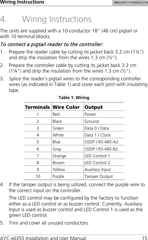
>
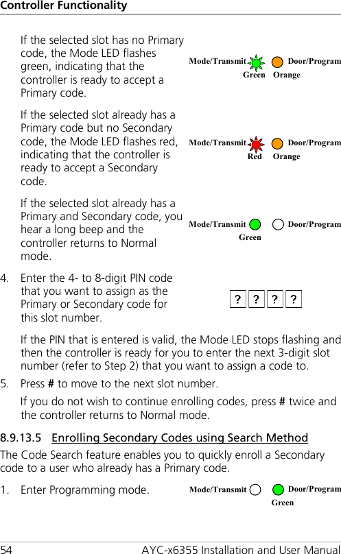
Rosslare
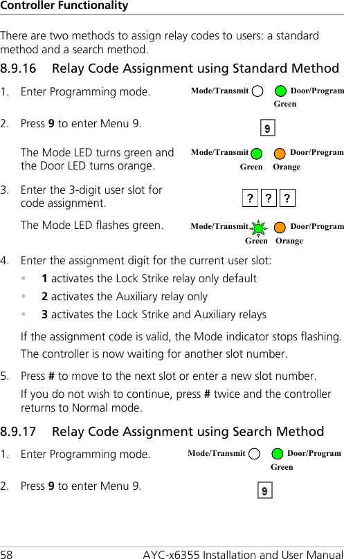
>
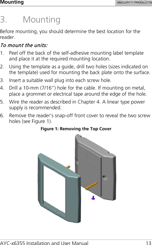
AYCX6X55 User Manual
Users Manual
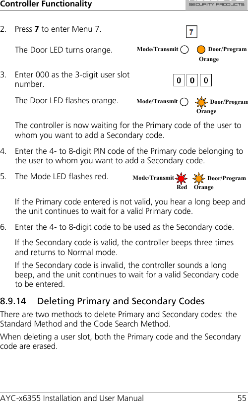
Navigation menu
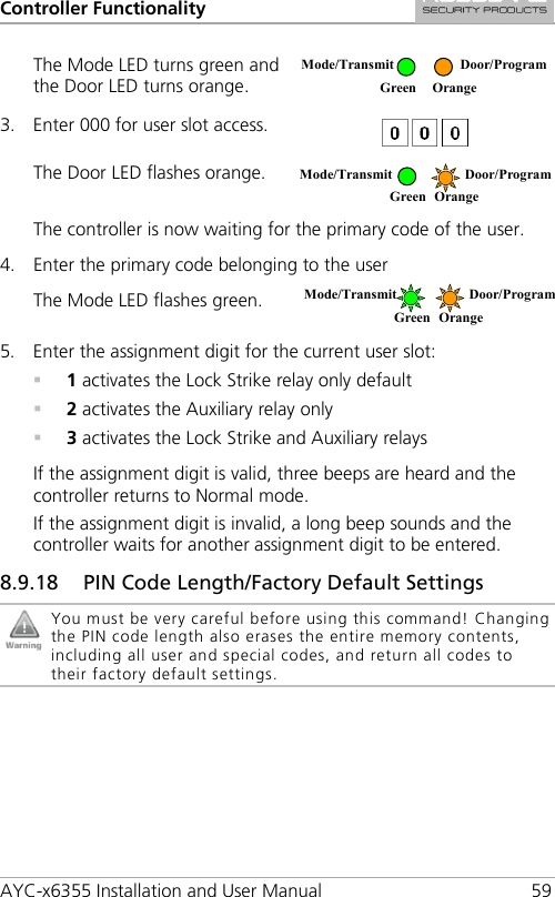
Upload a User Manual
Namespaces
Wiki Guide
HTML
PDF
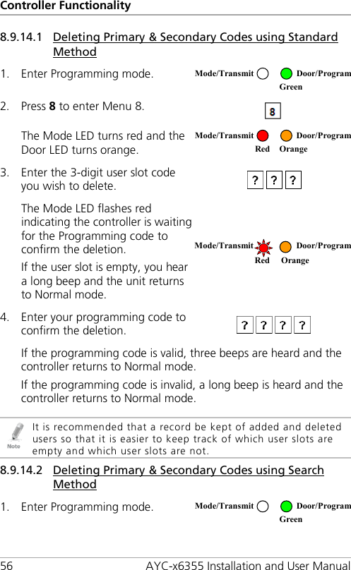
Info
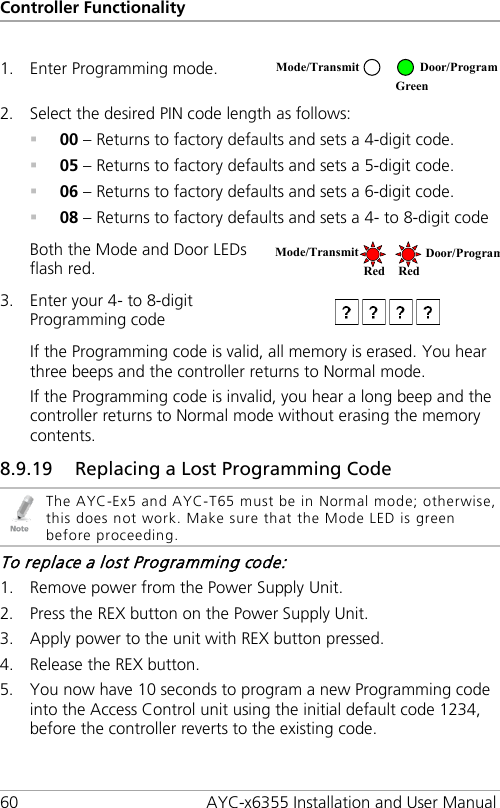
Views
User Manual
Discussion / Help
Navigation