Rosslare AYR6255 RGB Proximity Card Reader User Manual AY R6255 Installation and Operation Manual
Rosslare Enterprises Ltd RGB Proximity Card Reader AY R6255 Installation and Operation Manual
Rosslare >
User Manual
AY-R6255
Illuminated RFID Reader
Installation and Operational Manual
Copyright © 2015 by Rosslare. All rights reserved.
This manual and the information contained herein are proprietary to ROSSLARE
ENTERPRISES LIMITED and/or its related companies and/or subsidiaries’
(hereafter: "ROSSLARE"). Only ROSSLARE and its customers have the right to
use the information.
No part of this manual may be re-produced or transmitted in any form or by any
means, electronic or mechanical, for any purpose, without the express written
permission of ROSSLARE.
ROSSLARE owns patents and patent applications, trademarks, copyrights, or
other intellectual property rights covering the subject matter in this manual.
TEXTS, IMAGES, AND ILLUSTRATIONS INCLUDING THEIR ARRANGEMENT IN
THIS DOCUMENT ARE SUBJECT TO THE PROTECTION OF COPYRIGHT LAWS
AND OTHER LEGAL RIGHTS WORLDWIDE. THEIR USE, REPRODUCTION, AND
TRANSMITTAL TO THIRD PARTIES WITHOUT EXPRESS WRITTEN PERMISSION
MAY RESULT IN LEGAL PROCEEDINGS.
The furnishing of this manual to any party does not give that party or any third
party any license to these patents, trademarks, copyrights or other intellectual
property rights, except as expressly provided in any written agreement of
ROSSLARE.
ROSSLARE reserves the right to revise and change this document at any time,
without being obliged to announce such revisions or changes beforehand or
after the fact.

Table of Contents
AY-R6255 Installation and Operation Manual iii
Table of Contents
1. Introduction ................................................................ 7
2. Technical Specifications .............................................. 8
3. Mounting Instructions ................................................ 9
4. Wiring Instructions ................................................... 10
5. Operating Instructions .............................................. 12
5.1 Lighting ................................................................................ 12
5.2 DIP Switch Settings for Output and Input Formats ................... 13
6. Testing the Reader .................................................... 14
A. Limited Warranty ...................................................... 15


List of Tables
AY-R6255 Installation and Operation Manual v
List of Tables
Table 1: Wiring Colors ..................................................................................... 10
Table 2: Operations Table ................................................................................ 12
Table 3: Output Format ................................................................................... 13
Table 4: Read Format....................................................................................... 13

Notice and Disclaimer
vi AY-R6255 Installation and Operation Manual
Notice and Disclaimer
This manual’s sole purpose is to assist installers and/or users in the safe and
efficient installation and usage of the system and/or product described herein.
BEFORE ATTEMPTING TO INSTALL AND/OR USE THE SYSTEM, THE INSTALLER AND THE
USER MUST READ THIS MANUAL AND BECOME FAMILIAR WITH ALL SAFETY
REQUIREMENTS AND OPERATING PROCEDURES.
The system must not be used for purposes other than those for which it
was designed.
The use of the software associated with the system and/or product, if
applicable, is subject to the terms of the license provided as part of the
purchase documents.
ROSSLARE exclusive warranty and liability is limited to the warranty and
liability statement provided in an appendix at the end of this document.
This manual describes the maximum configuration of the system with the
maximum number of functions, including future options. Therefore, not all
functions described in this manual may be available in the specific system
and/or product configuration you purchased.
Incorrect operation or installation, or failure of the user to effectively
maintain the system, relieves the manufacturer (and seller) from all or any
responsibility for consequent noncompliance, damage, or injury.
The text, images and graphics contained in the manual are for the purpose
of illustration and reference only.
All data contained herein is subject to change without prior notice.
In no event shall manufacturer be liable for any special, direct, indirect,
incidental, consequential, exemplary or punitive damages (including,
without limitation, any and all damages from business interruption, loss of
profits or revenue, cost of capital or loss of use of any property or capital or
injury).
All graphics in this manual are for reference only, some deviation between
the image(s) and the actual product may occur.
All wiring diagrams are intended for reference only, the photograph or
graphic of the PCB(s) are intended for clearer illustration and
understanding of the product and may differ from the actual PCB(s).

Introduction
AY-R6255 Installation and Operation Manual 7
1. Introduction
The AY-R6255 is 13.56 MHz RFID reader and is installed when using
access control systems. This is a unique product that has a variety of
options to control the reader's illumination according to various
settings. An example of this are the settings that enable users to set
the reader to project green light when everything is normal and red in
case of emergency; this is done by adjusting the inputs accordingly.
This product is compatible with any Rosslare controller that supports
Wiegand 26-Bit, Wiegand 32-Bit, Wiegand 34-Bit, or Wiegand 40-Bit
protocols, as well with any third-party controllers that support the
same Wiegand inputs.
The panel links are used to set various conditions between events and
outputs to get the required illumination from the reader.

Technical Specifications
8 AY-R6255 Installation and Operation Manual
2. Technical Specifications
Electrical Characteristics
Power Supply Type Linear (recommended)
Operating Voltage Range 12–16 VDC
Maximum Input Current Standby: 100 mA
Read: 250 mA
Tamper Output Open collector, active low, max. sink
current 16 mA
Read Range* (max) MIFARE Classic EV1®: 7 cm (2.8 in.)
Felica/MIFARE Plus®/DESFire®: 3 cm
(1.2 in.)
ISO1443B: 5 cm (2.0 in.)
China ID: 2 cm (0.8 in.)
Maximum Cable Distance to
Controller
150 m (500 ft)
RE Modulation ASK @ 13.56 MHz
Output Format Wiegand 26-Bit, Wiegand 32-Bit,
Wiegand 34-Bit, Wiegand 40-Bit
Environmental Characteristics
Operating Temp. Range -31°C to 63°C (-25°F to 145°F)
Operating Humidity Range 0 to 95% (non-condensing)
Physical Characteristics
Height x Width x Depth 120 x 89 x 21 mm
(4.7 x 3.5 x 0.8 in.)
Weight 202 g (7.1 oz)
* Measured using a Rosslare proximity card or equivalent. Range also depends
on electrical environment and proximity to metal.
Mounting Instructions
AY-R6255 Installation and Operation Manual 9
3. Mounting Instructions
Installation of an RFID reader adjacent to metallic surfaces
might alter the reader’s specifications. To diminish this
interference, use a plastic spacer when mounting the reader.
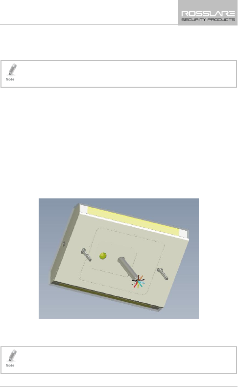
When mounting the reader, you must remove the snap-off cover to
access the screw holes.
To mount the reader:
1. Determine an appropriate mounting position for the reader.
2. Screw off the back of the unit and place it at the desired
mounting position.
3. Using the template as a guide, drill two holes (hole size is
indicated on mounting template) for mounting the reader to the
surface (Figure 1).
Figure 1: Mounting Template
4. Drill a 10-mm (7/16”) hole for the cable.
5. Route the interface cable from the reader to the controller.
The proximity reader is also mountable using strong epoxy glue.
After application, firmly hold the reader in place until the glue
dries

Wiring Instructions
10 AY-R6255 Installation and Operation Manual
4. Wiring Instructions
The AY-R6255 is supplied with a 10-wire 45-cm (18”) pigtail,
comprising a 6-conductor cable.
To connect the reader to the controller:
1. Prepare the reader cable by cutting its jacket back 4.5 cm (1¼”)
and strip the wires 1.3 cm (½”).
2. Prepare the controller cable by cutting its jacket back 3.2 cm
(1¼”) and stripping the wires 1.3 cm (½”).
3. Splice the reader’s pigtail wires to the corresponding controller
wires and cover each connection.
Table 1: Wiring Colors
Color Wiring
Black Ground
Red Vin
Green Data 0
White Data 1
Brown G.LED
Purple Tamper
Yellow SET 0
Blue SET 1
Gray SET 2
Orange SET 3
If the tamper output is being utilized, connect the purple wire to
the correct input on the controller.

Wiring Instructions
AY-R6255 Installation and Operation Manual 11
4. Trim and cover all unused conductors.
• The individual wires from the reader are color-coded according the
Wiegand standard.
• When using a separate power supply for the reader, this supply and
that of the controller, must have a common ground.
• The reader’s cable shield wire should preferably be attached to an
earth ground, or a signal ground connection at the panel, or power
supply end of he cable. This configuration is best fro shielding the
Reader cable from external interference

Operating Instructions
12 AY-R6255 Installation and Operation Manual
5. Operating Instructions
5.1 Lighting
Table 2 shows the settings for Set 0 through Set 3, which determine
the color of the unit’s lighting.
Table 2: Operations Table
Operation Set 0 Set 1 Set 2 Set 3
Green 0 0 0 0
Green with dimming 0 0 0 1
Red 0 0 1 0
Red with dimming 0 0 1 1
Blue 0 1 0 0
Blue with dimming 0 1 0 1
Purple 0 1 1 0
Purple with dimming 0 1 1 1
Yellow 1 0 0 0
Yellow with dimming 1 0 0 1
Cyan/Aqua 1 0 1 0
Cyan/Aqua with dimming 1 0 1 1
White 1 1 0 0
White with dimming 1 1 0 1
No Illumination 1 1 1 0
7 colors circularly with dimmer 1 1 1 1
1 – Not connected; 0 – Connected to the ground
Operating Instructions
AY-R6255 Installation and Operation Manual 13
5.2 DIP Switch Settings for Output and Input
Formats
Setting the DIP Switches of Pins 1 and 2 determine the output format
of the reader (Table 3), while Pins 3 and 4 determine the card format
that is read (Table 4).
Pins 5 through 8 are for future use.
Table 3: Output Format
Pin 1 Pin 2 Output
0 0 Wiegand 26-Bit
0 1 Wiegand 32-Bit
1 0 Wiegand 34-Bit
1 1 Wiegand 40-Bit
Table 4: Read Format
Pin 3 Pin 4 Read
0 0 ISO14443A
0 1 ISO14444B
1 0 ISO15693.Felica.Topaz
1 1 China ID/ ISO14443A

Testing the Reader
14 AY-R6255 Installation and Operation Manual
6. Testing the Reader
Once the reader has been wired to a power supply and the controller,
it should be tested.
To test the reader:
1. Power up the reader. The beeper activates 3 times after which the
LED lights up green (according to Set 0, Set 1, Set 2, and Set 3
setup). This indicates that the reader is working properly.
The default is that the reader switches colors circularly. The color
can be set according to the input wires.
2. Present the appropriate type of proximity card to the reader. The
LED turns green (if set to default) and a short beep is emitted,
indicating that the card was read properly by to proximity reader.

Limited Warranty
AY-R6255 Installation and Operation Manual 15
A. Limited Warranty
The full ROSSLARE Limited Warranty Statement is available in the
Quick Links section on the ROSSLARE website at
www.rosslaresecurity.com.
Rosslare considers any use of this product as agreement to the
Warranty Terms even if you do not review them.
Caution:
This device complies with Part 15 of the FCC rules and Industry Canada license-exempt RSS
standard(s). Operation is subject to the following two conditions: (1) this device may not cause
harmful interference, and (2) this device must accept any interference received, including
interference that may cause undesired operation.
The manufacturer is not responsible for any radio or TV interference caused by unauthorized
modifications or change to this equipment. Such modifications or change could void the user’s
authority to operate the equipment.
This radio transmitter (identify the device by certification number or model number if Category II)
has been approved by Industry Canada to operate with the antenna types listed below with the
maximum permissible gain indicated. Antenna types not included in this list, having a gain greater
than the maximum gain indicated for that type, are strictly prohibited for use with this device.
This equipment has been tested and found to comply with the limits for a Class B digital device,
pursuant to part 15 of the FCC Rules. These limits are designed to provide reasonable protection
against harmful interference in a residential installation. This equipment generates, uses and can
radiate radio frequency energy and, if not installed and used in accordance with the instructions,
may cause harmful interference to radio communications. However, there is no guarantee that
interference will not occur in a particular installation. If this equipment does cause harmful
interference to radio or television reception, which can be determined by turning the equipment
off and on, the user is encouraged to try to correct the interference by one or more of the
following measures:
-- Reorient or relocate the receiving antenna.
-- Increase the separation between the equipment and receiver.
-- Connect the equipment into an outlet on a circuit different from that to which the receiver is
connected.
-- Consult the dealer or an experienced radio/TV technician for help.
The device has been evaluated to meet general RF exposure requirement.
To maintain compliance with FCC’s RF exposure guidelines, this equipment should be
installed and operated with a minimum distance of 20cm between the radiator and your
body.

AY-R6255
Asia Pacific, Middle
East, Africa
Rosslare Enterprises Ltd.
Kowloon Bay, Hong Kong
Tel: +852-2795-5630
Fax: +852-2795-1508
support.apac@rosslaresecurity.com
United States and
Canada
Rosslare Security Products, Inc.
Southlake, TX, USA
Toll Free: +1-866-632-1101
Local: +1-817-305-0006
Fax: +1-817-305-0069
support.na@rosslaresecurity.com
Europe
Rosslare Israel Ltd.
Rosh HaAyin, Israel
Tel: +972-3-938-6838
Fax: +972-3-938-6830
support.eu@rosslaresecurity.com
Latin America
Rosslare Latin America
Buenos Aires, Argentina
Tel: +54-11-4001-3104
support.la@rosslaresecurity.com
China
Rosslare Electronics (Shenzhen) Ltd.
Shenzhen, China
Tel: +86-755-8610 6842
Fax: +86-755-8610 6101
support.cn@rosslaresecurity.com
India
Rosslare Electronics India Pvt Ltd.
Tel/Fax: +91-20-40147830
Mobile: +91-9975768824
sales.in@rosslaresecurity.com
0706-0960607+00