Rosslare HLX24TH Advanced Wireless Security Panels User Manual HLX 24
Rosslare Enterprises Ltd Advanced Wireless Security Panels HLX 24
Rosslare >
Users Manual
HLX-24TH Family
Advanced Wireless Security Panels
User Manual
Copyright © 2015 by Rosslare. All rights reserved.
This manual and the information contained herein are proprietary to ROSSLARE
ENTERPRISES LIMITED and/or its related companies and/or subsidiaries’ (hereafter:
"ROSSLARE"). Only ROSSLARE and its customers have the right to use the information.
No part of this manual may be re-produced or transmitted in any form or by any means,
electronic or mechanical, for any purpose, without the express written permission of
ROSSLARE.
ROSSLARE owns patents and patent applications, trademarks, copyrights, or other
intellectual property rights covering the subject matter in this manual.
TEXTS, IMAGES, AND ILLUSTRATIONS INCLUDING THEIR ARRANGEMENT IN THIS
DOCUMENT ARE SUBJECT TO THE PROTECTION OF COPYRIGHT LAWS AND OTHER
LEGAL RIGHTS WORLDWIDE. THEIR USE, REPRODUCTION, AND TRANSMITTAL TO THIRD
PARTIES WITHOUT EXPRESS WRITTEN PERMISSION MAY RESULT IN LEGAL
PROCEEDINGS.
The furnishing of this manual to any party does not give that party or any third party any
license to these patents, trademarks, copyrights or other intellectual property rights,
except as expressly provided in any written agreement of ROSSLARE.
ROSSLARE reserves the right to revise and change this document at any time, without
being obliged to announce such revisions or changes beforehand or after the fact.

Table of Contents
HLX-24 User Manual iii
Table of Contents
1. Introduction ....................................................................... 8
2. Technical Specifications ................................................... 9
3. Operating the HLX-24 ..................................................... 10
3.1 Quick Reference ............................................................................... 10
3.2 About Everyday Operation ................................................................ 10
3.3 Arming Options ................................................................................ 10
3.3.1 Arm Away ................................................................................................. 10
3.3.2 Arm Home ................................................................................................ 11
3.3.3 Quick Arming ............................................................................................ 11
3.3.4 Instant Arming .......................................................................................... 11
3.3.5 Forced Arming .......................................................................................... 11
3.3.6 Exit Delay .................................................................................................. 11
3.3.7 Exit Restart ................................................................................................ 12
3.4 Disarm Mode .................................................................................... 12
3.4.1 Entry Delay ................................................................................................ 12
3.5 System Alarm ................................................................................... 13
3.5.1 Abort Window Time .................................................................................. 13
3.5.2Alarm Cancel ............................................................................................ 13
3.5.3 Zone Cross ................................................................................................ 13
3.5.4 Swinger Zone Shutdown ............................................................................ 13
3.5.5 Fire Alarm ................................................................................................. 14
4. System Overview ............................................................ 15
4.1 HLX-24 Wireless Panel ...................................................................... 15
4.2 The LCD Display ................................................................................ 16
4.3 The Keypad ...................................................................................... 18
4.4 Sound Indicators ............................................................................... 19
4.5 LED Indicators ................................................................................... 19
5. User Menu Structure ....................................................... 21

Table of Contents
iv HLX-24 User Manual
6. Telephony Voice Response Menu .................................. 23
6.1 General ............................................................................................ 23
6.2 Arming Submenu ............................................................................. 23
6.3 Automation Submenu ...................................................................... 24
6.4 Status Report .................................................................................... 24
7. Reading the Event Log ................................................... 25
8. User Menu Options ......................................................... 26
8.1 Accessing the User Menu .................................................................. 26
8.2 Changing the Master Code ............................................................... 26
8.3 Defining User Codes ......................................................................... 26
8.4 Authorization Codes ......................................................................... 27
8.5 Silent Exit .......................................................................................... 27
8.6 Setting Date and Time ...................................................................... 27
8.7 Defining Date and Time Format ........................................................ 27
8.8 Setting Zone Bypass .......................................................................... 28
8.8.1 Enabling Zone Bypass ................................................................................ 28
8.8.2 Defining Bypass Zones ............................................................................... 28
8.9 Enrolling a Remote Control ............................................................... 29
8.10 Deleting a Remote Control ................................................................ 29
8.11 Setting Phone Numbers .................................................................... 30
8.12 Registration Code (HLX-24IP model only) .......................................... 30
9. Maintenance .................................................................... 31
9.1 Dismounting the Control Panel ......................................................... 31
9.2 Replacing the 4 AA Backup Batteries ................................................. 31
A. Declaration of Conformity ............................................. 32
B. Limited Warranty ............................................................ 33

List of Figures
HLX-24 User Manual v
List of Figures
Figure 1: HLX-24 Panel ................................................................................. 15
Figure 2: The Keypad.................................................................................... 18
Figure 3: Replacing the Backup Batteries....................................................... 31

List of Tables
vi HLX-24 User Manual
List of Tables
Table 1: Quick Reference to Keypad Buttons ................................................. 10
Table 2: HLX-24 Wireless Panel ..................................................................... 16
Table 3: Display Options ............................................................................... 17
Table 4: Keypad Functions ............................................................................ 18
Table 5: Sound Indicators ............................................................................. 19
Table 6: Power LED Indicator ........................................................................ 19
Table 7: Status LED Indicator ........................................................................ 19
Table 8: Keypad Function Indicators ............................................................. 20
Table 9: User Menu Options ......................................................................... 21

Notice and Disclaimer
HLX-24 User Manual vii
Notice and Disclaimer
This manual’s sole purpose is to assist installers and/or users in the safe and
efficient installation and usage of the system and/or product, and/or software
described herein.
BEFORE ATTEMPTING TO INSTALL AND/OR USE THE SYSTEM, THE INSTALLER AND
THE USER MUST READ THIS MANUAL AND BECOME FAMILIAR WITH ALL SAFETY
REQUIREMENTS AND OPERATING PROCEDURES.
The system must not be used for purposes other than those for which it
was designed.
The use of the software associated with the system and/or product, if
applicable, is subject to the terms of the license provided as part of the
purchase documents.
ROSSLARE exclusive warranty and liability is limited to the warranty and
liability statement provided in an appendix at the end of this document.
This manual describes the maximum configuration of the system with the
maximum number of functions, including future options. Therefore, not
all functions described in this manual may be available in the specific
system and/or product configuration you purchased.
Incorrect operation or installation, or failure of the user to effectively
maintain the system, relieves the manufacturer (and seller) from all or any
responsibility for consequent noncompliance, damage, or injury.
The text, images and graphics contained in the manual are for the
purpose of illustration and reference only.
All data contained herein subject to change without prior notice.
In no event shall manufacturer be liable for any special, direct, indirect,
incidental, consequential, exemplary or punitive damages (including,
without limitation, any and all damages from business interruption, loss of
profits or revenue, cost of capital or loss of use of any property or capital
or injury).
All graphics in this manual are for reference only, some deviation between
the image(s) and the actual product may occur.
All wiring diagrams are intended for reference only, the photograph or
graphic of the PCB(s) are intended for clearer illustration and
understanding of the product and may differ from the actual PCB(s).

Introduction
8 HLX-24 User Manual
1. Introduction
The HLX-24 family of panels by Rosslare is the perfect wireless security system
for intrusion protection of the home, or small office providing security
monitoring and telephony IVR Voice messaging.
Users receive the latest RF technology in a wide selection of advanced wireless
sensors and remotes, and benefit from smooth and easy operation of a large
number of security and communication options.
The panel has two full split reporting features for communicating to central
station for Contact ID and telephony voice enabled event reporting.
The HLX-24 currently comes in two models:
HLX-24P – PSTN (landline) communication
HLX-24T – TCP/IP communication
In addition to the standard HLX-24P version, the HLX-24T version allows users
to control and monitor the status of the panel by using the HLX-24 mobile
application, HomeLogiX™APP from a smartphone. For more information, see
the
HLX-24 Mobile Application User Manual
.
Technical Specifications
HLX-24 User Manual 9
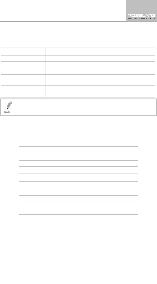
2. Technical Specifications
Electrical Characteristics
External Power Supply 220 VAC/50 Hz, 110 VAC/60 Hz
Operating Voltage Range 15 VDC, 800 mA
Input Current Standby: 150 mA
Max: 300 mA
Backup Batteries
4 AA (1800 mAh rechargeable batteries are
included)
Display Two Line, 16 characters, white backlit LCD
PGM Open Collector Output 100 mA, PTC protected
Local Siren 87 dBA @ 1 m (3.28 ft)
Communication (RF) Characteristics
Frequencies 433.92 MHz (G version)
868.35 MHz (H version)
RF Jamming Detection UL/EN selectable
Anti-collision Proprietary RF protocol
Programmable No-activity Timer 1–30 minutes, per zone
Reporting Three private telephone numbers.
Telephone and Modem Built in dialer & 2400 Baud modem
Environmental Characteristics
Operating Temp. Range 0ºC to 60ºC (32ºF to 140ºF) without battery
0ºC to 45ºC (32ºF to 113ºF) with battery
Storage Temp. Range -25ºC to 70ºC (-13ºF to 158ºF)
Operating Humidity 0 to 85% at 30ºC non-condensing
Dimensions
Height x Width x Depth 174 x 152 x 48 mm
(8.5 x 5.7 x 1.9 in.)
Weight 330 g (11.6 oz)
Operating the HLX-24
10 HLX-24 User Manual
3. Operating the HLX-24
This chapter describes the day to day operation of the system, as well as
provides a quick reference for the Arming/Disarming buttons in the system.
3.1 Quick Reference
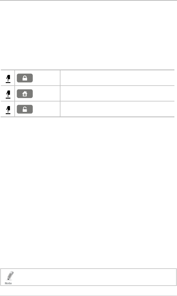
Use the following buttons on the keypad for quick arming the system:
Table 1: Quick Reference to Keypad Buttons
AWAY
Arms all sensors and detectors for use when there is no
one at home/office.
HOME
Arms all perimeter sensors and detectors as defined by
the installer. For use when home/office is occupied.
DISARM
Disarms all armed sensors and detectors.
For more on the keys and their function, see Section 4.3.
3.2 About Everyday Operation
The HLX-24 system allows you to ensure the security of your home, both while
you are home and while you are away. The system allows you to control
attached subsystems and appliances such as garage doors, lights, heating, and
air conditioner via an expandable PGM output.
3.3 Arming Options
The following subsections describe the arming options available to the installer.
3.3.1 Arm Away
ARM AWAY is the full arming of the system, best used when there is no one is
at home or in the office. In Away mode, the system enters Alarm mode if there
is a zone violation, regardless of perimeter or interior type.
If the installer enabled the “Unvacated Premises” option, the system may
trigger Arm Home (Stay) mode automatically if the system was armed in Arm
Away mode, but there was no exiting from the delay zone during the exit
delay period.
To arm the system using AWAY:
1. Verify that the system is ready for arming.
2. Press the AWAY arming key.
3. Enter your user code.
If the user arms the system as AWAY by remote control, a squawk
acknowledgement is produced twice in the local sounders.

Operating the HLX-24
HLX-24 User Manual 11
3.3.2 Arm Home
Home arming is an arming of all perimeter sensors and detectors as defined by
the installer. This is intended for when home or office is occupied.
To arm the system using HOME:
1. Verify that the system is ready for arming.
2. Press the HOME arming key.
3. Enter your user code.
If the user arms the system as HOME by remote control, a squawk
acknowledgement is produced twice in the local sounders.
3.3.3 Quick Arming
Quick arming allows arming the system without code entry. If Quick Arming is
enabled (by the installer during setup), a long press on one of the arming
buttons activates Quick Arming.
3.3.4 Instant Arming
If Instant Arming mode is enabled (by the installer during configuration), the
system skips the exit delay, cancels the entry delay configured, and initiates the
alarm, which instantly causes an alarm to go off upon violation of any zone.
To instantly arm the system:
1. Verify that the system is ready for arming.
2. Press either the HOME or the AWAY arming key.
3. Enter your user code.
4. Press the same arming key once again.
3.3.5 Forced Arming
If Forced Arming is enabled, the system is able to arm even when zones are in
violation (open) but not defined as bypassed. In such a case, the system arms,
effectively bypassing the open zone. Once the open zone is closed, the system
completes arming, adding the previously bypassed zone to the monitored
zones.
3.3.6 Exit Delay
An exit delay enables the user to arm the system and exit the site through a
specified door (determined as a delay zone) using a predetermined path after
arming the system, without setting off an alarm.
A progress annunciation of slow-rate warning beeps sound when the system is
armed. The system counts down the last 10 seconds of the delay if the voice
capability is configured; otherwise, the warning beeps are faster. The exit delay
is set at 60 seconds by default.
The user can use the Silent Exit feature to silence the audible progress
annunciation of the exit delay.
Operating the HLX-24
12 HLX-24 User Manual
If Silent Exit is active, the Exit Time is doubled for that exit period only, but
does not exceed 255 seconds.
During Home arming, the system ignores all interior zones as well as the
predefined delay zones.
3.3.7 Exit Restart
When this feature is enabled, an Exit Restart delay occurs on the second zone
opening within the same zone and the Exit Delay time is doubled. If it is
disabled, the same zone may be opened several times while in the Exit Delay
countdown.
3.4 Disarm Mode
When disarmed, the HLX-24 system is in Standby mode. Alarms trigger only
for panic, fire, 24-hour audible, and silent conditions.
In this state, the system continuously checks zone status and holds the Ready
status parameter. This parameter determines whether the system is ready to be
armed. The system becomes Ready to Arm when zones are either closed or
bypassed.
To disarm the system:
1. Press the Disarm key.
2. Enter your user code.
• If the user disarms the system during Exit/Entry mode, the progress
annonciation is silenced on the first keystroke of the user code. If the code
is invalid, the progress annonciation resumes.
• If the user disarms the system during the Abort time, the alarm
announciation is silenced on the first keystroke of the user code. If the code
is invalid, the alarm resumes.
• If the user disarms the system by remote control, a squawk
acknowledgement is produced once in the local sounders.
3.4.1 Entry Delay
An entry delay enables the user to enter the site through a specified door
(determined as a delay zone) using a predetermined path, without setting off
an alarm. The entry delay is set at 30 seconds by default.
After entry, the user must disarm the system before the entry delay expires. A
progress annunciation of slow-rate warning beeps sound upon detection of
the specified zone. The system counts down the last 10 seconds of the delay
indication if enabled or the warning beeps become faster.

Operating the HLX-24
HLX-24 User Manual 13
3.5 System Alarm
Alarms trigger for panic, fire, 24-hour audible and silent conditions for 24
hours a day, 7 days a week. When premises are in Armed Away, all delayed,
interior, and perimeter zones are protected. When premises are in Armed
Home (Stay), all delayed and perimeter zones are protected (interior zones are
ignored).
Once in Alarm mode, the system transmits an alarm event to the monitoring
station (if configured).
Call Waiting Policy:
*70 is added to the beginning of the phone number to disable call waiting to
ensure that the connection failure was not due to the use of the Call Waiting
Cancel feature on a non-call-waiting line.
In addition, the system notifies the user of the alarm by phone (if configured).
A local siren is heard if configured.
All events are saved to an event log.
3.5.1 Abort Window Time
When this option is enabled, the system sounds a warning, but the central
station does not receive notification of the alarm if the user disarms the system
within the specified alarm abort time.
3.5.2 Alarm Cancel
The Alarm Cancel window is a period of time starting at the end of the abort
window period, during which a user can cancel the alarm. The Alarm Cancel
window applies to all alarms that have been subjected to the Abort window. If
an alarm had previously been transmitted, an Alarm Cancel event signal is
transmitted to the monitoring station if the control panel is disarmed during
the Alarm Cancel window.
3.5.3 Zone Cross
The zone cross option requires an opening of two zones within a given time
period to initiate an alarm event sequence. If one linked zone is opened and
the other linked zone is not opened, a zone cross error is sent to the
monitoring station.
3.5.4 Swinger Zone Shutdown
If there are two or more opening events in an armed non-fire zone, the system
ignores the zone. The zone is restored after disarming the system or
automatically after 8 hours.

Operating the HLX-24
14 HLX-24 User Manual
3.5.5 Fire Alarm
Fire alarm verification is an available option on fire zones. When used the
system begins and Alarm Transmission Sequence once the conditions for fire
alarm verification are met.
The Fire Verify setting double checks the state of the fire detectors.
When there is a fire sensor alarm signal, a siren is heard immediately. A 60-
second retard-reset period starts during which every additional fire alarm signal
is ignored. After this period, an additional timeout of 60 seconds starts, which is
the confirmation period, during which a fire sensor alarm signal causes an event
transmission to the monitoring station.
When the confirmation period expires, the fire zone is automatically restored
and ready for a new fire alarm session.
System Overview
HLX-24 User Manual 15
4. System Overview
The main components of the HLX-24 wireless panel are:
HLX-24 Wireless Panel
The LCD Display
The Keypad
Sound Indicators
LED Indicators
4.1 HLX-24 Wireless Panel
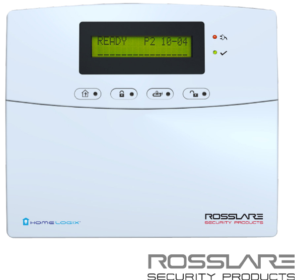
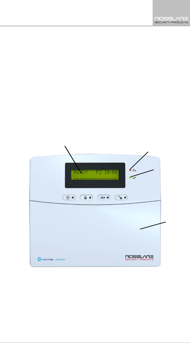
Figure 1 presents the components of the wireless panel.
Figure 1: HLX-24 Panel
Display
Power Indicator
Status Indicator
Keypad Door
System Overview
16 HLX-24 User Manual
Table 2 describes the components in the panel:
Table 2: HLX-24 Wireless Panel
Menu Use to navigate between menus
Power indicator Power LED
Red on: system is ON
Red flashing: AC power failure
Status indicators on the
‘Arm Home’, Disarm and
Arm Away buttons
Status LED
Green LED when the system is disarmed using the
‘Disarm’ button
Red on: System armed
Red off: System disarmed
Flash: Entry and exit delay (according to beep rate)
Keypad door Open to access the keypad buttons
Local sounder On the back of the device
Local emergency button Keep pressed for 3 seconds to sound a standard panic
alarm
Display LCD display
Enter Accept an entry or selection
Panic Alarm is followed by a report to the Central Station and audible siren as
defined by the installer.
4.2 The LCD Display
The LCD display clearly shows the system status. The display consists of two
rows. The bottom line is divided into two and displays the system status and
events.
When in Idle mode, the first line displays the system's name (HomeLogiX™ by
default) while the second line shows the system status. For example, the
second line displays Ready.
Pressing # (pound key), toggles the first line display between the System name
display and the Time & Date display.
The system status is displayed on the left of the bottom line. The events are
displayed on the right of the system status. If there is more than one event, the
event display toggles every two seconds. There are several display options as
described in Table 3:
System Overview
HLX-24 User Manual 17
Table 3: Display Options
System Status
Ready Indicates that all zones are in Normal state and the system is ready
for arming.
Not ready Indicates that at least one zone is open and the system is not ready
for arming.
Press Enter to see which zones are open. If there is more than one
open zone, pressing Enter or Menu displays the next open zone.
When there are no more open zones, the display returns to the idle
view. You can also exit the active zone view by pressing the ESC,
Away or Home buttons.
Event Display
TRBL Indicates that a problem exists on the system. The following
System
Troubles
may appear in the TRBL message:
• Battery Missing
• Dead Battery
• Low battery
• Power failure (AC Fail)
• RF jamming
• Line Fail
• Communication Fail
• Tamper
In addition, the following Zone Troubles may appear in the TRBL
message:
• Tamper
• Low battery
• Supervision (failure)
MEM Indicates an alarm in memory
LOG Indicates that a trouble event appears in the log file
ABT Indicates that at least one zone alarm aborted
CNL Indicates that a cancel alarm was transmitted to the central station
MSG Indicates that a personal message is waiting
System Overview
18 HLX-24 User Manual
4.3 The Keypad
The keypad is used to program the wireless panel and to arm and disarm the
sensors.
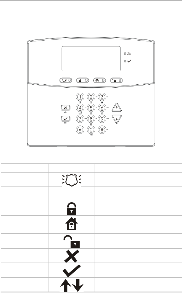
Figure 2: The Keypad
Table 4 describes the keypad functions:
Table 4: Keypad Functions
Key Icon Function
Panic
When pressed for 3 seconds a standard
panic alarm sounds
Keys 0 – 9 Enters alphanumeric entries
Press 0 to enter a space
Arm Away
Arms all sensors and detectors for use
when there is no one at home/office
Arm Home
Arms all perimeter sensors and detectors
as defined by the installer (for use when
home/office is occupied)
Disarm
Disarms all armed sensors and detectors
ESC/Back
Ignores an entry or moves one level up in
a menu
Enter
Accepts an entry or selection
Up/Down Arrows
Use to navigate between menus
System Overview
HLX-24 User Manual 19
4.4 Sound Indicators
Table 5 describes the sounds are emitted by the system and keypad:
Table 5: Sound Indicators
Sound Sounded When
Single beep A key is pressed
Long Beep Illegal key entry
Three short beeps An entry is successfully accepted.
Four short beeps a
minute
If enabled, on trouble condition.
Short beep every
second
An exit/entry delay is activated. (Beep sounded every 0.5
seconds during last 10 seconds of delay.
This table does not include actual alarm sounds.
The audible indication of a fire zone differs from that of a normal intrusion
zone.
4.5 LED Indicators
Table 6, Table 7, and Table 8 describe the LED indicators of the various panel
indicators.
Table 6: Power LED Indicator
Power LED
(Red/Green)
Status
Green ON Normal AC mode
FLASHES red every 0.5 seconds AC Failure
Table 7: Status LED Indicator
Status LED
(Red/Green)
Status
Green ON Panel ready
Red ON Panel not ready
Green FLASHES every 1 second Walk Test mode
System Overview
20 HLX-24 User Manual
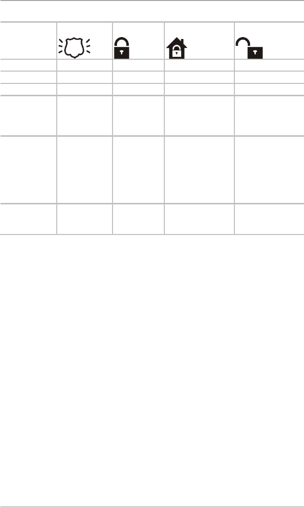
Table 8: Keypad Function Indicators
Panel
Status
Panic
Arm Away
Arm Home
Disarm
Disarm OFF OFF OFF ON
Arm Home OFF OFF ON OFF
Arm Away OFF ON OFF OFF
Arming Home OFF OFF FLASHES every 1
second (until last
10 seconds flashes
every 0.5 seconds)
OFF
Arming Away OFF FLASHES
every 1
second (until
last 10
seconds
flashes every
0.5 seconds)
OFF OFF
Panic ON Previous LED
status
continues
Previous LED status
continues
Previous LED status
continues

User Menu Structure
HLX-24 User Manual 21
5. User Menu Structure
The User menu enables configuring the basic user settings, such as setting the
date and time and changing user codes. You can define one Master user and
up to twenty additional users, each with an individual code.
Settings marked with an “M” can be accessed by the Master user only, and
appear only if the master code is entered.
If the master code has not been specified and the installer has set the zone
bypass to Off, the User menu is unavailable to regular users.
To enter the User menu:
1. On the panel, press Menu repeatedly until the screen displays
User
.
2. Press Enter.
3. Enter the Master user code (the default code is 1234) and press Enter.
The system is locked out for 90 seconds after entering 5 wrong codes.
The User menu options are displayed in Table 9:
Table 9: User Menu Options
Select To
(M) Edit Master
Code
Change the master code (see Section 8.2).
(M) User Codes Specify user codes 1 through 20.
If the user code exists, you can edit the code or delete it by
pressing # (see Section
8.3).
Authorization Code Specify the code that is used to configure the system’s settings
with the remote programming software HR-P02.
The default code is 1234.
Silent Exit Choose between disabling and enabling the progress
annunciation during exit delay.
The default is Disabled.
(M) Set Date & Time Set the Time & Date, as specified in Section 8.5.
(M) Date & Time
Format
Specify the format in which the time is specified: 24 hour
format or AM/PM. By toggling between the two using the
Menu button.
Specify the format in which the date is specified: DD-MM-YY or
MM-DD-YY (see Section 8.7)

User Menu Structure
22 HLX-24 User Manual
Select To
Zone Bypass Enables you to arm the system by bypassing/un-bypassing
selected zones (see Section 8.8).
This option is enabled if manual bypass has been enabled by the
installer.
Note: Zone bypass can be triggered only if the zone was
enrolled.
Remote Controls Enroll remote controls for quick activation of the system (see
Section
8.9)
(M) Private
Numbers
Specify up to three private telephone numbers (see Section
8.11).
Walk Test When entering the detector’s Test mode, the red and green
LEDs on the panel flash every second simultaneously, and the
display shows “receiving…”.
If the alert monitoring station reporting options is enabled, an
E607 event is transmitted.
The Walk Test sequence timeout is for 15 minutes. In the last 5
minutes, a squawk is heard every two seconds in addition the
green and red LEDs flash simultaneously to indicate that the
testing period will be terminated in another five minutes.
If the system walk detector test is terminated, an R607 restore
event is transmitted (if enabled).
During the Walk Test, each successful detector violation causes
a squawk and the signal strength is displayed.
In the conclusion of the Walk Test, the installer may browse
through the recorded results by using the Menu button. Each
browsing of a record is followed by the E613 event transmission
with the relevant zone indication.
For 24-H and fire zones, reporting trouble event E380 is sent to
the monitoring station.

Telephony Voice Response Menu
HLX-24 User Manual 23
6. Telephony Voice Response Menu
6.1 General
IVR (Interactive Voice Response) features include telephony voice assistance,
where the panel uses voice through the telephone to prompt the user. Either
the system or a remote private telephone can initiate an IVR session.
IVR session Initiated by a Remote Telephone User: The remote telephone
user initiates an IVR session by calling the system’s number. The system
answers after a preset number of rings. Press * to initiate connection. The
system broadcasts the site description and waits for a code. The remote
user must enter a valid master code to start a session.
IVR session initiated by the System: The system initiates a session (if
enabled by the installer) upon an event occurrence. The system calls the
private number and asks that you to press * to initiate the connection
after which the system broadcasts the site and the event description. The
user must then enter a valid master code to enter the IVR menu. The
system hangs up after approximately 60 seconds of inactivity. If there is no
answer from a private phone or if the user hangs up, the system switches
to the next private number. The system retries calling the programmed
private phones for a pre-programmed number of attempts unless the user
disconnects the call session by pressing 9, in which case the session is
stopped completely.
The system switches to voice menu mode when a valid master code is entered.
During voice menu mode, the system uses voice messages for menu options.
Follow the voice instructions.
Press 0 at any time to jump one level up in the menus.
The following options are available:
Press 1 to enter the arming options submenu
Press 2 to enter the automation options submenu
Press 4 to receive a status report
Press 9 to exit the menu and disconnect the system.
6.2 Arming Submenu
After entering the arming submenu the following options are available:
Press 1 to “Arm Away”
Press 2 to “Arm Home”
Press 3 to “Disarm”
Press 0 to return to the previous menu
The system status is announced.
Telephony Voice Response Menu
24 HLX-24 User Manual
Please note that when arming, the status change is only announced after the
exit delay timeout.
Disconnect the phone to terminate the session or press 0 to return to the
previous menu.
6.3 Automation Submenu
After entering the automation submenu, you hear the following:
Press 0 to return to the previous menu
The system then requests the following:
Press 1 to turn the PGM on
Press 2 to turn the PGM off.
Note that if no acknowledgment is heard after your selection, disconnect the
phone to terminate the session or press 0 to return to the previous menu.
6.4 Status Report
Enter the Status submenu to hear the system status.
During a PSTN IVR session, the system does not activate its local IVR.

Reading the Event Log
HLX-24 User Manual 25
7. Reading the Event Log
The HLX-24 event log stores up to 250 events. When the log is full, the new
incoming event replaces the oldest event.
Events are displayed in a chronological order and include the date and time of
their occurrence.
To access the Event Log:
1. Access the event log by pressing 8 on the keypad when the system is in
Normal mode.
2. To read an event, enter the master code and press Enter.
3. Browse the event log using the Menu button or go directly to an event by
entering the event number using the numeric keypad.
4. Press Enter to view the date and time of the occurrence.
5. Enter a number from 001 to 250 to locate the requested event.
The log indication is off in Disarm mode.
The event registration into log reoccurs after system disarming.
User Menu Options
26 HLX-24 User Manual
8. User Menu Options
8.1 Accessing the User Menu
To access the User menu:
1. Press the Menu button to reach the User menu and press Enter.
You are asked to enter the Master code.
2. Enter your 4-digit Master code.
Entering the correct code brings you to the user menu submenus. If a
wrong code is entered, the system emits a long beep indicating an error
and waits once again for the correct code to be entered.
Inactivity for 30 seconds causes the system to return to Normal mode.
3. Once in the
User menu,
use the Menu button to browse the submenus.
4. Press Enter to access the desired submenu as detailed below.
8.2 Changing the Master Code
You can change the master code.
This feature is only for Master users.
To change the master code:
1. Using the Menu button, select Edit Master Code and press Enter.
2. Using the numeric keypad, enter the new master code and press Enter to
save.
The master code is changed.
8.3 Defining User Codes
You can use the panel to define up to twenty users.
This feature is only for Master users.
To define user codes:
1. Using the Menu button, select User Codes and press Enter.
2. Using the numeric keypad, select a user (1–20) and press Enter.
3. Using the numeric keypad, type a 4-digit code and press Enter to save.
4. Press the pound key (#) to delete an existing number.
User Menu Options
HLX-24 User Manual 27
8.4 Authorization Codes
You can set the code that is used to configure the system’s settings with the
remote programming software HR-P02.
To set the authorization codes:
1. Using the Menu button, select Authorization Code and press Enter.
2. Using the numeric keypad, type a 4-digit code and press Enter to save.
8.5 Silent Exit
You can choose between disabling and enabling the progress annunciation
during exit delay. The default is Disabled.
To set the silent exit:
1. Using the Menu button, select Silent Exit and press Enter.
2. Using the Menu button, select either Enable or Disable.
3. Press Enter to confirm.
8.6 Setting Date and Time
You can set the date and time that appears on the panel.
This feature is only for Master users.
To set the date and time:
1. Using the Menu button, select Date and Time and press Enter.
2. Two options appear:
a. Set Time – Enter the time using the alphanumeric keypad and press
Enter.
b. Set Date – Enter the date using the alphanumeric keypad and press
Enter.
The date and time are set.
8.7 Defining Date and Time Format
You can set the format used for how the date and time appear on the panel.
This feature is only for Master users.
To set the date and time format:
1. Select Date and Time Format with Menu button, press Enter.
2. Specify the format in which the time is displayed: toggle between 24-hour
format and AM/PM using the Menu button.
3. Press Enter to confirm your selection.
User Menu Options
28 HLX-24 User Manual
4. Specify the format in which the date is displayed: DD-MM-YY or MM-DD-
YY.
5. Press Enter to confirm your selection.
The date and time format is set.
8.8 Setting Zone Bypass
You can define certain zones to be bypassed when arming the system to deal
with different situations, such as when the sensors battery is low and is
sending an event, or when arming the system while someone is still on
premises in certain areas. In general, you need to also determine whether to
activate zone bypass.
This feature is available to both User and Master level users, and is only active if
it is set by the installer.
8.8.1 Enabling Zone Bypass
For the zone bypass option to work, the feature must first be enabled and at
least one zone must be enrolled and/or active.
If Zone Bypass is disabled, pressing Enter shows “BYPASS DISABLED”. If Zone
Bypass is enabled but there is no enrolled or active zone, pressing Enter shows
“NO ACTIVE ZONE”.
To enable zone bypass:
1. Using the Menu button, select
Zone Bypass
and press Enter.
2. Using the Menu and Enter buttons, access the
Set Activation
submenu.
3. Using the Menu button, choose to either Activate or Deactivate the
zone bypass feature.
4. Press Enter to save.
8.8.2 Defining Bypass Zones
You can define each of the 24 zones to be bypassed when arming the system.
The zone bypass is deactivated once the system is disarmed following the
bypassed arming.
To define bypass zones:
1. Using the Menu button, select
Zone Bypass
and press Enter.
2. Press Enter to access the
Select Zone
submenu.
3. Using the numeric keypad or the Menu button, select the specific zone to
define and press Enter to confirm your selection.
4. Using the Menu button, choose to either Bypass or Un-Bypass the
selected zone.
5. Press Enter to save your selection.

User Menu Options
HLX-24 User Manual 29
6. Arm the system using one of the arming options.
7. To arm the system again using the same bypass settings, press 6 followed
by one of the arming buttons.
8.9 Enrolling a Remote Control
You can enroll up to eight remote controls, and specify functions for each
button on the remote control. The default functions are ARM AWAY, ARM
HOME, OFF, PANIC, and STATUS (voice announcement of panel status).
Arming or disarming the system using a remote control is identical to arming
and disarming manually.
To activate the Panic alarm, user must press the Panic button twice.
To enroll a remote control and specify a function:
1. Using the Menu button, select Remote Controls and press Enter.
2. Select the desired remote control number 01–08 by either browsing the
remotes using the Menu button or by entering the remote number using
the numeric keypad.
3. Enroll the remote control when the “
WAITING FOR SIGNAL”
message is
displayed by pressing a button on the remote you wish to enroll.
4. When the signal is detected, you are asked to press the Enter button to
store and save your selection.
5. Once the selection is stored, you can then choose to configure each of the
remote control buttons to behave in one of the following options:
Restore Default (reset to its original functionality)
Operate PGM
Status Request
6. At any time, you can press the ESC button to exit the menu.
Once you exit the menu (after saving the enrollment) you cannot change the
button’s behavior, unless you delete the remote and re-enroll it.
8.10 Deleting a Remote Control
To delete a remote control:
1. Using the Menu button, select Remote Controls and press Enter.
2. Select the pre-enrolled remote control number 01–08 by either browsing
the remotes using the Menu button or by entering the remote number
using the numeric keypad.
You are asked to confirm deletion.
3. Press Enter to delete the remote control or the ESC button to go back.

User Menu Options
30 HLX-24 User Manual
8.11 Setting Phone Numbers
You can specify up to three private telephone numbers that are called by the
wireless panel when an event occurs.
To define phone numbers:
1. Using the Menu button, select Private Numbers and press Enter.
2. Using the Menu button or numeric keypad, choose between private
numbers 1, 2 or 3 and press Enter.
3. Using the numeric keypad, enter the telephone number and press Enter
to confirm.
4. Press the pound key (#) to delete an existing number.
The private numbers are set.
For PABX, use the digit followed by "," and then the full number.
8.12 Registration Code (HLX-24IP model only)
The registration code is the MAC address of the HLX-24IP control panel. This is
used to create a user account when using the HomeLogiX™APP, which allows
you to control and monitor your HLX-24IP control panel from a smartphone.
For more information see the
HLX-24 Mobile Application User Manual
.
Maintenance
HLX-24 User Manual 31
9. Maintenance
This chapter is for the installer.
9.1 Dismounting the Control Panel
To release the panel from the mounted back-plate:
1. Unlock the locking hooks on the top of the back plate by lifting them up
and out of the recesses on top of the panel.
2. Pull the top of the panel away from the wall to disconnect the connector
from the back-plate.
3. Remove the panel from the lower posts of the back-plate.
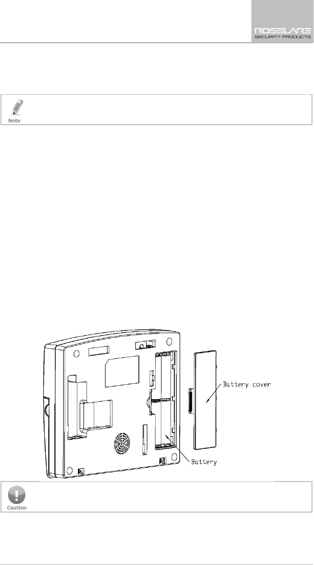
9.2 Replacing the 4 AA Backup Batteries
To replace the backup batteries:
1. Dismount the panel.
2. Remove the battery compartment cover (Figure 3).
3. Replace the batteries.
4. Replace the cover.
Figure 3: Replacing the Backup Batteries
Do not mix between different rechargeable batteries type and different
charging levels

Declaration of Conformity
32 HLX-24 User Manual
A. Declaration of Conformity
This device complies with Part 15 of the FCC Rules. Operation is subject to the
following two conditions:
This device may not cause harmful interference.
This device must accept any interference received, including interference
that may cause undesired operation.
Changes or modifications not expressly approved by the party responsible for
compliance could void the user's authority to operate the equipment.
This equipment has been tested and found to comply with the limits for a
Class B digital device, pursuant to part 15 of the FCC Rules. These limits are
designed to provide reasonable protection against harmful interference in a
residential installation.
This equipment generates, uses, and can radiate radio frequency energy and, if
not installed and used in accordance with the instructions, may cause harmful
interference to radio communications. However, there is no guarantee that
interference will not occur in a particular installation. If this equipment does
cause harmful interference to radio or television reception, which can be
determined by turning the equipment off and on, the user is encouraged to try
to correct the interference by one or more of the following measures:
Reorient or relocate the receiving antenna.
Increase the separation between the equipment and receiver.
Connect the equipment into an outlet on a circuit different from that to
which the receiver is connected.
Consult the dealer or an experienced radio/TV technician for help.
Changes or modifications to this equipment not expressly approved by the
party responsible for compliance (Rosslare Ltd.) could void the user’s authority
to operate the equipment.

Limited Warranty
HLX-24 User Manual 33
B. Limited Warranty
The full ROSSLARE Limited Warranty Statement is available in the Quick Links
section on the ROSSLARE website at www.rosslaresecurity.com.
Rosslare considers any use of this product as agreement to the Warranty Terms
even if you do not review them.

HLX-24
Asia Pacific, Middle East,
Africa
Rosslare Enterprises Ltd.
Kowloon Bay, Hong Kong
Tel: +852 2795-5630
Fax: +852 2795-1508
support.apac@rosslaresecurity.com
United States and Canada
Rosslare Security Products, Inc.
Southlake, TX, USA
Toll Free: +1-866-632-1101
Local: +1-817-305-0006
Fax: +1-817-305-0069
support.na@rosslaresecurity.com
Europe
Rosslare Israel Ltd.
Rosh HaAyin, Israel
Tel: +972 3 938-6838
Fax: +972 3 938-6830
support.eu@rosslaresecurity.com
Latin America
Rosslare Latin America
Buenos Aires, Argentina
Tel: +54-11-4001-3104
support.la@rosslaresecurity.com
China
Rosslare Electronics (Shenzhen) Ltd.
Shenzhen, China
Tel: +86 755 8610 6842
Fax: +86 755 8610 6101
support.cn@rosslaresecurity.com
India
Rosslare Electronics India Pvt Ltd.
Tel/Fax: +91 20 40147830
Mobile: +91 9975768824
sales.in@rosslaresecurity.com
0706-0960567+00