Rosslare PYR-3011G Wireless Passive Infrared Ceiling - Mount Motion Detector PYR-3011 User Manual Installation Manual
Rosslare Enterprises Ltd Wireless Passive Infrared Ceiling - Mount Motion Detector PYR-3011 Installation Manual
Rosslare >
Users Manual
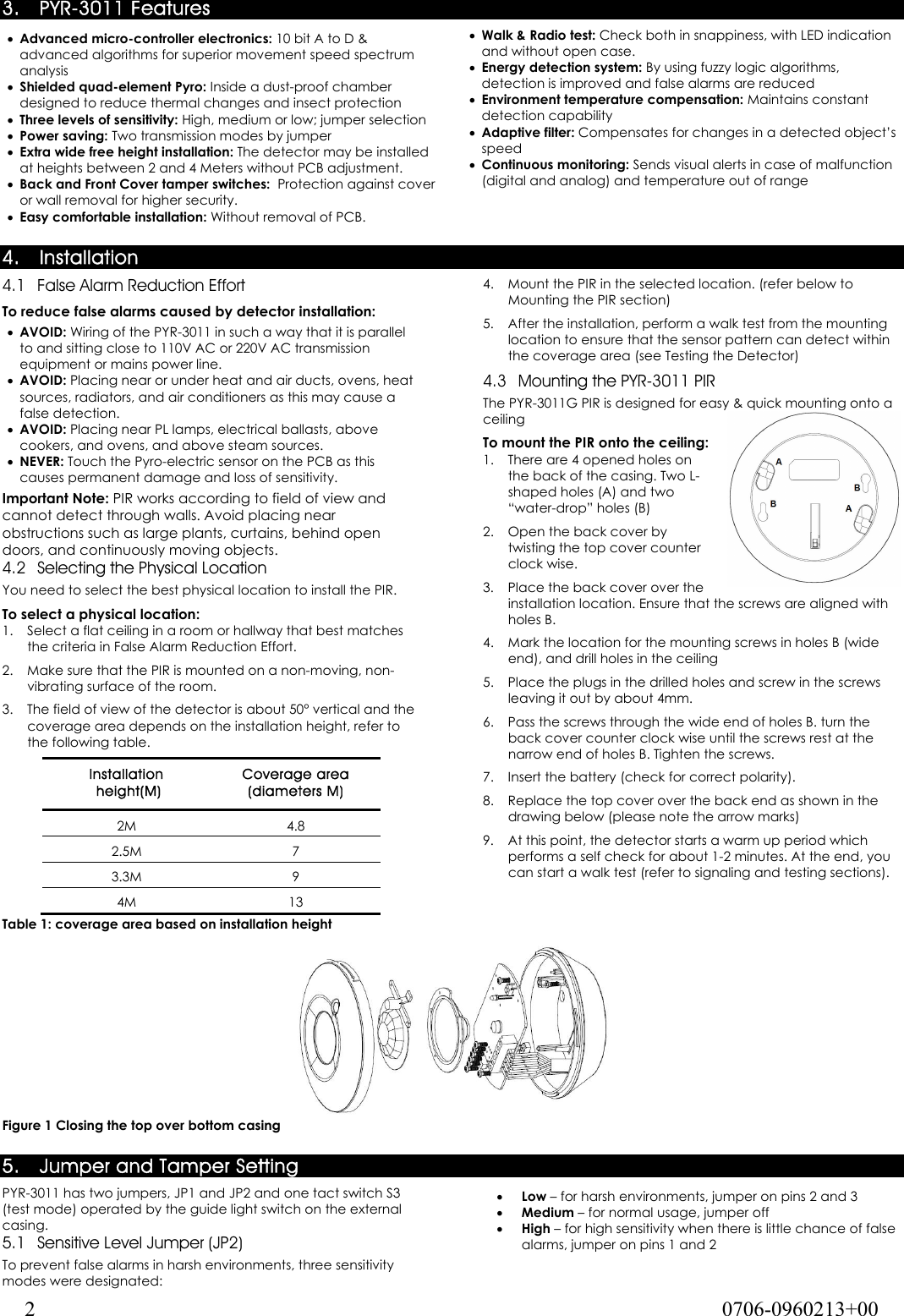
![PYR-3011 Installation Instructions Wireless Passive Infrared Ceiling-Mount Motion Detector 1 0706-0960213+00 1. Introduction The PYR-3011 Digital Wireless Passive Infrared (PIR) ceiling-mount motion detector is a high-performance, ultra low power intrusion sensor with advanced design ideal for residential and commercial applications. This unit works with Rosslare’s control panels like HomeLogiX™, which is wireless, and AuraSys™, which is wired. For the PYR-3011 to work with AuraSys™, the AuraSys™ panel must have the XR-16 wireless expansion. The PIR senses slight motion within a coverage area by detecting infrared energy with a Pyroelectric sensor. Serving as an anti-intrusion sensor, the PIR can monitor open space within line of sight. “Walk & Radio” test is an easy, as well as friendly, ceiling installation that makes it very comfortable for placing and setting. The PYR-3011 uses fuzzy logic to improve detections and reduce false alarms. It also provides digital temperature compensation and self-test capability. The PYR-3011 is supplied with front and back tampers for high security. As a wireless device, it includes a supervised mechanism as well as a battery-checker and tamper announcement. Note 1: This product must be installed professionally, and has only one available channel. Note 2: Pursuant to FCC §15.21 [ 54 FR 17714 , Apr. 25, 1989, as amended at 68 FR 68545 , Dec. 9, 2003], changes or modifications made to equipment, which are not expressly approved by Rosslare Enterprises, Ltd., may void the user's authority to operate the equipment. 2. Technical Specifications 2.1 Optical Characteristics Lens Type: High density Polytilan lens Optical Filter: White light protection Maximum Coverage: 7m (23ft) diameter at 2.4M (7.874ft) height. 2.2 Electrical Characteristics Battery type: CR123 (3V/1300mhA) Current Consumptions: Standby 15µa, 10ma transmission. Battery Life (nominal): 3 years (150tr/day) Detector Type: Quad-matrix PYRO IR element (IR filter 5um÷14um) Alarm Signaling: Red LED 2 seconds on (push button setting) Events Transmission: Alarm, Tamper, Low battery. Sensitivity: 3 levels fuzzy logic (jumper setting) Speed Detect: 0.2m/s ÷ 3m/s ∆ t= 1.1°C (0.66 ft/s ÷ 9.84 ft /s ∆ t= 34° F) Temperature Compensation: Digital dual slope (+/- 1°C) Tamper Switches: Back and front Cover tampers Supervisory Signals: Electronic malfunction, temperature out of range (by flashing LED) Arming types: Normal- 2 minutes sleep, followed by last alarm Dynamic- 2 minutes sleep, followed by last movement (retriggerable) Test modes- walk test (no sleep) 1 min Radio Test- 10 transmissions 2.3 RF Transmission Characteristics Frequency: model H = 868.35 MHz; model G = 433.92 MHz Range: 200 meters (656 ft) open field conditions Supervision transmission: automatic, at 20-minute intervals Self check: 3 hours from last alarm (retriggered) 2.4 Environmental Characteristics Operating Environment: Indoor use Operating Temperature: -10 to 60°C (14 to 140°F) Operating Humidity: 0 to 95% (non-condensing) RFI Protection: >20 V/m up to 1000 MHz Physical Characteristics Dimensions top diameter x height x bottom diameter: 106 x 31 x 71 mm (4.2 x 1.2 x 2.8 inch) Weight: 106 grams (3.8 oz) Note: The PYR-3011 is an indoor use PIR, and should not be used in outdoor applications. 2.5](https://usermanual.wiki/Rosslare/PYR-3011G/User-Guide-1179895-Page-1.png)