Rosslare PYR-3011G Wireless Passive Infrared Ceiling - Mount Motion Detector PYR-3011 User Manual Installation Manual
Rosslare Enterprises Ltd Wireless Passive Infrared Ceiling - Mount Motion Detector PYR-3011 Installation Manual
Rosslare >
Users Manual

PYR-3011
Installation Instructions
W
ireless Passive Infrared
Ceiling-Mount Motion Detector
1 0706-0960213+00
1. Introduction
The PYR-3011 Digital Wireless Passive Infrared (PIR) ceiling-mount
motion detector is a high-performance, ultra low power intrusion
sensor with advanced design ideal for residential and commercial
applications. This unit works with Rosslare’s control panels like
HomeLogiX™, which is wireless, and AuraSys™, which is wired. For
the PYR-3011 to work with AuraSys™, the AuraSys™ panel must
have the XR-16 wireless expansion.
The PIR senses slight motion within a coverage area by detecting
infrared energy with a Pyroelectric sensor. Serving as an anti-
intrusion sensor, the PIR can monitor open space within line of sight.
“Walk & Radio” test is an easy, as well as friendly, ceiling installation
that makes it very comfortable for placing and setting.
The PYR-3011 uses fuzzy logic to improve detections and reduce
false alarms.
It also provides digital temperature compensation and self-test
capability.
The PYR-3011 is supplied with front and back tampers for high
security.
As a wireless device, it includes a supervised mechanism as well as
a battery-checker and tamper announcement.
Note 1: This product must be installed professionally, and has
only one available channel.
Note 2: Pursuant to
FCC §15.21 [ 54 FR 17714
, Apr. 25, 1989, as
amended at 68 FR
68545 , Dec. 9, 2003],
changes or
modifications made to
equipment, which are
not expressly approved
by Rosslare Enterprises,
Ltd., may void the user's
authority to operate the
equipment.
2. Technical Specifications
2.1 Optical Characteristics
Lens Type: High density Polytilan lens
Optical Filter: White light protection
Maximum Coverage: 7m (23ft) diameter at 2.4M (7.874ft) height.
2.2 Electrical Characteristics
Battery type: CR123 (3V/1300mhA)
Current Consumptions: Standby 15µa, 10ma transmission.
Battery Life (nominal): 3 years (150tr/day)
Detector Type: Quad-matrix PYRO IR element (IR filter 5um÷14um)
Alarm Signaling: Red LED 2 seconds on (push button setting)
Events Transmission: Alarm, Tamper, Low battery.
Sensitivity: 3 levels fuzzy logic (jumper setting)
Speed Detect: 0.2m/s ÷ 3m/s ∆ t= 1.1°C (0.66 ft/s ÷ 9.84 ft /s ∆ t= 34°
F)
Temperature Compensation: Digital dual slope (+/- 1°C)
Tamper Switches: Back and front Cover tampers
Supervisory Signals: Electronic malfunction, temperature out of
range (by flashing LED)
Arming types:
Normal- 2 minutes sleep, followed by last alarm
Dynamic- 2 minutes sleep, followed by last movement
(retriggerable)
Test modes- walk test (no sleep) 1 min
Radio Test- 10 transmissions
2.3 RF Transmission Characteristics
Frequency: model H = 868.35 MHz; model G = 433.92 MHz
Range: 200 meters (656 ft) open field conditions
Supervision transmission: automatic, at 20-minute intervals
Self check: 3 hours from last alarm (retriggered)
2.4 Environmental Characteristics
Operating Environment: Indoor use
Operating Temperature: -10 to 60°C (14 to 140°F)
Operating Humidity: 0 to 95% (non-condensing)
RFI Protection: >20 V/m up to 1000 MHz
Physical Characteristics
Dimensions top diameter x height x bottom diameter: 106 x 31 x 71
mm (4.2 x 1.2 x 2.8 inch)
Weight: 106 grams (3.8 oz)
Note: The PYR-3011 is an indoor use PIR, and should not be
used in outdoor applications.
2.5

2 0706-0960213+00
3. PYR-3011 Features
• Advanced micro-controller electronics: 10 bit A to D &
advanced algorithms for superior movement speed spectrum
analysis
• Shielded quad-element Pyro: Inside a dust-proof chamber
designed to reduce thermal changes and insect protection
• Three levels of sensitivity: High, medium or low; jumper selection
• Power saving: Two transmission modes by jumper
• Extra wide free height installation: The detector may be installed
at heights between 2 and 4 Meters without PCB adjustment.
• Back and Front Cover tamper switches: Protection against cover
or wall removal for higher security.
• Easy comfortable installation: Without removal of PCB.
• Walk & Radio test: Check both in snappiness, with LED indication
and without open case.
• Energy detection system: By using fuzzy logic algorithms,
detection is improved and false alarms are reduced
• Environment temperature compensation: Maintains constant
detection capability
• Adaptive filter: Compensates for changes in a detected object’s
speed
• Continuous monitoring: Sends visual alerts in case of malfunction
(digital and analog) and temperature out of range
4. Installation
4.1 False Alarm Reduction Effort
To reduce false alarms caused by detector installation:
• AVOID: Wiring of the PYR-3011 in such a way that it is parallel
to and sitting close to 110V AC or 220V AC transmission
equipment or mains power line.
• AVOID: Placing near or under heat and air ducts, ovens, heat
sources, radiators, and air conditioners as this may cause a
false detection.
• AVOID: Placing near PL lamps, electrical ballasts, above
cookers, and ovens, and above steam sources.
• NEVER: Touch the Pyro-electric sensor on the PCB as this
causes permanent damage and loss of sensitivity.
Important Note: PIR works according to field of view and
cannot detect through walls. Avoid placing near
obstructions such as large plants, curtains, behind open
doors, and continuously moving objects.
4.2 Selecting the Physical Location
You need to select the best physical location to install the PIR.
To select a physical location:
1. Select a flat ceiling in a room or hallway that best matches
the criteria in False Alarm Reduction Effort.
2. Make sure that the PIR is mounted on a non-moving, non-
vibrating surface of the room.
3. The field of view of the detector is about 50° vertical and the
coverage area depends on the installation height, refer to
the following table.
Installation
height(M)
Coverage area
(diameters M)
2M 4.8
2.5M 7
3.3M 9
4M 13
Table 1: coverage area based on installation height
4. Mount the PIR in the selected location. (refer below to
Mounting the PIR section)
5. After the installation, perform a walk test from the mounting
location to ensure that the sensor pattern can detect within
the coverage area (see Testing the Detector)
4.3 Mounting the PYR-3011 PIR
The PYR-3011G PIR is designed for easy & quick mounting onto a
ceiling
To mount the PIR onto the ceiling:
1. There are 4 opened holes on
the back of the casing. Two L-
shaped holes (A) and two
“water-drop” holes (B)
2. Open the back cover by
twisting the top cover counter
clock wise.
3. Place the back cover over the
installation location. Ensure that the screws are aligned with
holes B.
4. Mark the location for the mounting screws in holes B (wide
end), and drill holes in the ceiling
5. Place the plugs in the drilled holes and screw in the screws
leaving it out by about 4mm.
6. Pass the screws through the wide end of holes B. turn the
back cover counter clock wise until the screws rest at the
narrow end of holes B. Tighten the screws.
7. Insert the battery (check for correct polarity).
8. Replace the top cover over the back end as shown in the
drawing below (please note the arrow marks)
9. At this point, the detector starts a warm up period which
performs a self check for about 1-2 minutes. At the end, you
can start a walk test (refer to signaling and testing sections).
Figure 1 Closing the top over bottom casing
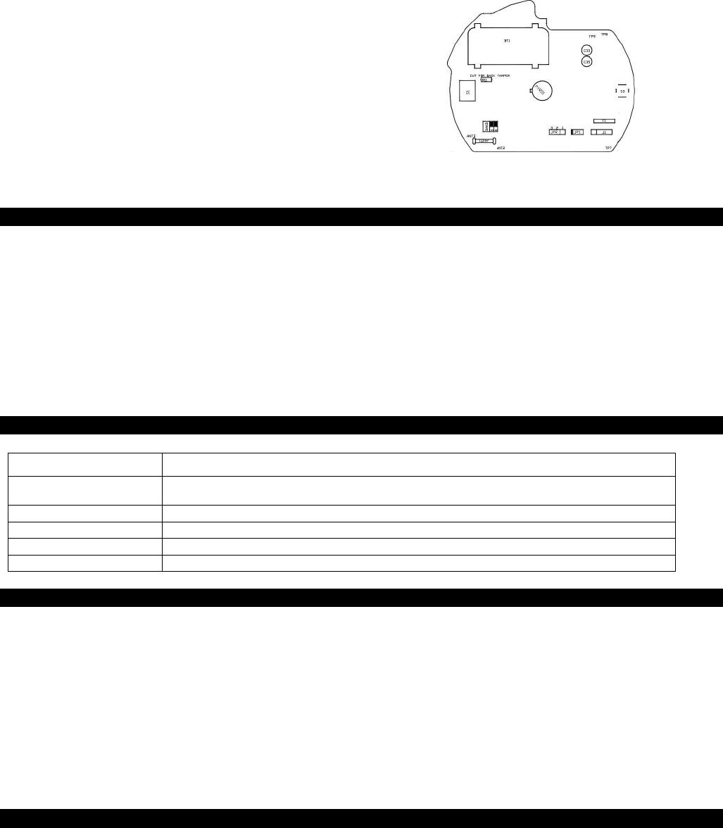
5. Jumper and Tamper Setting
PYR-3011 has two jumpers, JP1 and JP2 and one tact switch S3
(test mode) operated by the guide light switch on the external
casing.
5.1 Sensitive Level Jumper (JP2)
To prevent false alarms in harsh environments, three sensitivity
modes were designated:
• Low – for harsh environments, jumper on pins 2 and 3
• Medium – for normal usage, jumper off
• High – for high sensitivity when there is little chance of false
alarms, jumper on pins 1 and 2
3 0706-0960213+00
5.2 APS – Auto Power Save Mode (JP1)
To save power, the PYR-3011 goes into sleep mode after sending
an alarm. The time the device will be latent is set by the radio
mode jumper, JP1.
• Normal (always 2 minutes between alarms) – no jumper.
• Dynamic (2 minutes retriggered between alarms) – jumper
on.
When the dynamic mode is set, an alarm event will be sent only if
there were 2 minutes of silence prior to the current alarm. This
setting is useful for places with a high level of traffic, such as
factories, shops, etc.
5.3 Back Tamper (R11)
The PYR-3011 has both front and back tamper detection. Front
tamper detection is on by default and it is activated when the
cover is opened cannot be changed. The back tamper detection
is activated when the detector is pulled off the ceiling and is
disabled by default, to enable the back tamper detection cut the
back tamper wire - R11 - which is marked on the PCB as a scissor
print.
5.4 Test Mode Switch (S3)
This pushbutton is used for walk test or radio test, as follows:
Walk Test – press for 1 second only; PIR functionality will be
evaluated during the calibration process, for a 1 minute period.
(After self check at power up the walk test is automatic enable for
2 minutes.)
Radio Test – press for more than 3 seconds; the red indicator
illuminates. 10 Alarms events are transmitted with 4 second
intervals for a total transmission time of approximately 40 seconds.
This test is to insure clear RF passes between the detector and the
control panel.
In all modes the LED will remain activate at all trouble
announcements.
Refer also to panel manual for RF testing details.
Figure 2 PCB front view
6. Testing the Detector
The PYR-3011 PIR has a built-in walk test function where the LED of
the PIR is enabled. This test is used to check the detection of the
PIR and the coverage pattern.
To perform a walk test:
1. Ensure all of the settings in the PIR are adjusted as necessary for
the location according to the installation instructions above.
2. Insert battery in the closed case as described above. The LED
flashes on for 2 seconds and off for 2 seconds for a period of 1
minute. Then the LED turns off. At this point a walk test can be
performed. As default, perform a walk test of 2 minute at the
end of the self test. If more than 2 minute goes past, refer to
paragraph 3.
3. Place a magnet over the right side of the lens for 1 second
only.
4. With the LED enabled the LED flashes every time the detector
detects motion. There is a two second wait period before the
next detection.
5. It is recommended that the installer test the detection by going
over the protected area and seeing that the detection
pattern is good.
6. After 1 minute, the LED goes off. If a new walk test is needed,
go again to paragraph 3.
7. Signaling Table
The LED on the front of the PYR-3011 is used to send several signals to the user. The following table describes the signals for different activities:
Activity LED Signal
Warm-Up The LED flashes on for 2 seconds and off for 2 seconds for a period of 1 minute. If the warm-up is
successful, the LED stops flashing and the system is ready for detection.
Detect Condition The LED flashes on for 2 seconds and then turns off.
PIR Problem The LED flashes on for 1 second and then off for 1 second. A PIR check is conducted every 3 hours.
Temperature Problem The LED flashes on in short bursts.
Weak Battery LED OFF and ON alternately during Alarm, Tamper event
8. Testing the Detector
The PYR-3011 PIR has a built-in walk test function where the LED of
the PIR is enabled. This test is used to check the detection of the
PIR and the coverage pattern.
To perform a walk test:
1. Ensure all of the settings in the PIR are adjusted as necessary
for the location according to the installation instructions
above.
2. Insert battery in the closed case as described above. The
LED flashes on for 2 seconds and off for 2 seconds for a
period of 1 minute. Then the LED turns off. At this point a walk
test can be performed. As default, perform a walk test of 1
minute at the end of the self test. If more than 1 minute pasts,
refer to paragraph 3.
3. Push the guide light according to the required LED mode.
(Refer to setting test Mode, above)
4. With the LED enabled the LED flashes every time the detector
detects motion. There is a two second wait period before the
next detection.
5. It is recommended that the installer test the detection by
going over the protected area and seeing that the
detection pattern is good.
6. After 1 minute, the LED goes off. If a new walk test is needed,
go again to paragraph 3.
9. Low Battery Supervision
Prior to each RF transmission, the battery voltage is sampled. If
the voltage is low (as indicated by the red blinking light) for 3
sequential samples, a special message is sent. Once the battery
level returns to the minimum preset value, fault transmissions
cease.

10. Enrolling the Detector
After ending the self test, the detector can be enrolled. The
easiest way to enroll the detector is by opening and closing the
front tamper.
For specific steps to be followed for the enrolling, refer to the
manual supplied with the alarm panel.
11. Limited Warranty
ROSSLARE ENTERPRISES LIMITED S (Rosslare) ONE YEAR LIMITED
WARRANTY is applicable worldwide. This warranty supersedes any other
warranty. Rosslare's ONE YEAR LIMITED WARRANTY is subject to the
following conditions:
Warranty
Warranty of Rosslare's products extends to the original purchaser (Customer)
of the Rosslare product and is not transferable.
Products Covered By This Warranty and Duration
ROSSLARE ENTERPRISES LTD. AND / OR SUBSIDIARIES (ROSSLARE)
warrants that the PYR-3011 Wireless Passive Infrared Ceiling-Mount Motion
Detector, to be free from defects in materials and assembly in the course of
normal use and service. The warranty period commences with the date of
shipment to the original purchaser and extends for a period of 1 year (12
Months).
Warranty Remedy Coverage
In the event of a breach of warranty, ROSSLARE will credit Customer with the
price of the Product paid by Customer, provided that the warranty claim is
delivered to ROSSLARE by the Customer during the warranty period in
accordance with the terms of this warranty. Unless otherwise requested by
ROSSLARE ENTERPRISES LTD. AND / OR SUBSIDIARIES representative,
return of the failed product(s) is not immediately required.
If ROSSLARE has not contacted the Customer within a sixty (60) day holding
period following the delivery of the warranty claim, Customer will not be
required to return the failed product(s). All returned Product(s), as may be
requested at ROSSLARE ENTERPRISES LTD. AND /OR SUBSIDIARY’S sole
discretion, shall become the property of ROSSLARE ENTERPRISES LTD.
AND /OR SUBSIDIARIES.
To exercise the warranty, the user must contact Rosslare Enterprises Ltd. to
obtain an RMA number after which, the product must be returned to the
Manufacturer freight prepaid and insured
In the event ROSSLARE chooses to perform a product evaluation within the
sixty (60) day holding period and no defect is found, a minimum US$ 50.00 or
equivalent charge will be applied to each Product for labor required in the
evaluation.
Rosslare will repair or replace, at its discretion, any product that under normal
conditions of use and service proves to be defective in material or
workmanship. No charge will be applied for labor or parts with respect to
defects covered by this warranty, provided that the work is done by Rosslare
or a Rosslare authorized service center.
Exclusions and Limitations
ROSSLARE shall not be responsible or liable for any damage or loss resulting
from the operation or performance of any Product or any systems in which a
Product is incorporated. This warranty shall not extend to any ancillary
equipment not furnished by ROSSLARE, which is attached to or used in
conjunction with a Product, nor to any Product that is used with any ancillary
equipment, which is not furnished by ROSSLARE.
This warranty does not cover expenses incurred in the transportation, freight
cost to the repair center, removal or reinstallation of the product, whether or
not proven defective.
Specifically excluded from this warranty are any failures resulting from
Customer's improper testing, operation, installation, or damage resulting from
use of the Product in other than its normal and customary manner, or any
maintenance, modification, alteration, or adjustment or any type of abuse,
neglect, accident, misuse, improper operation, normal wear, defects or
damage due to lightning or other electrical discharge. This warranty does not
cover repair or replacement where normal use has exhausted the life of a part
or instrument, or any modification or abuse of, or tampering with, the Product if
Product disassembled or repaired in such a manner as to adversely affect
performance or prevent adequate inspection and testing to verify any warranty
claim.
ROSSLARE does not warrant the installation, maintenance, or service of the
Product. Service life of the product is dependent upon the care it receives and
the conditions under which it has to operate.
In no event shall Rosslare be liable for incidental or consequential damages.
Limited Warranty Terms
THIS WARRANTY SETS FORTH THE FULL EXTENT OF ROSSLARE
ENTERPRISES LTD. AND IT’S SUBSIDIARY’S WARRANTY.
THE TERMS OF THIS WARRANTY MAY NOT BE VARIED BY ANY PERSON,
WHETHER OR NOT PURPORTING TO REPRESENT OR ACT ON BEHALF OF
ROSSLARE.
THIS LIMITED WARRANTY IS PROVIDED IN LIEU OF ALL OTHER
WARRANTIES. ALL OTHER WARRANTIES EXPRESSED OR IMPLIED,
INCLUDING WITHOUT LIMITATION, IMPLIED WARRANTIES OF
MERCHANTABILITY AND FITNESS FOR A PARTICULAR PURPOSE, ARE
SPECIFICALLY EXCLUDED.
IN NO EVENT SHALL ROSSLARE BE LIABLE FOR DAMAGES IN EXCESS OF
THE PURCHASE PRICE OF THE PRODUCT, OR FOR ANY OTHER INCIDENTAL,
CONSEQUENTIAL OR SPECIAL DAMAGES, INCLUDING BUT NOT LIMITED TO
LOSS OF USE, LOSS OF TIME, COMMERCIAL LOSS, INCONVENIENCE, AND
LOSS OF PROFITS, ARISING OUT OF THE INSTALLATION, USE, OR INABILITY
TO USE SUCH PRODUCT, TO THE FULLEST EXTENT THAT ANY SUCH LOSS
OR DAMAGE MAY BE DISCLAIMED BY LAW.
THIS WARRANTY SHALL BECOME NULL AND VOID IN THE EVENT OF A
VIOLATION OF THE PROVISIONS OF THIS LIMITED WARRANTY.
12. Contact information
Asia Pacific, Middle East, Africa
Headquarters:
905-912 Wing Fat Industrial Bldg, 12 Wang Tai Road, Kowloon Bay HK
Tel:+852 2795-5630 Fax: +852 2795-1508
E-mail: support.apac@rosslaresecurity.com
United States and Canada
1600 Hart Court, Suite 103 Southlake, TX, USA 76092
Toll Free:+1-866-632-1101 Local:+1-817-305-0006 Fax: +1-817-305-0069
E-mail: support.na@rosslaresecurity.com
Europe
Global Technical Support & Training Center:
HaMelecha 22 Rosh HaAyin, Israel 48091
Tel: +972 3 938-6838 Fax: +972 3 938-6830
E-mail: support.eu@rosslaresecurity.com
South America
Pringles 868, 1640 Martinez Buenos Aires Argentina
Tel: +54 11 4798-0095 Fax: +54 11 4798-2228
E-mail: support.la@rosslaresecurity.com
Web Site: www.rosslaresecurity.com
4 0706-0960213+00