Rosslare SA-80G SA-80G User Manual SA 80A Installation Manual
Rosslare Enterprises Ltd SA-80G SA 80A Installation Manual
UserManual.wiki
>
Rosslare
>
SA 80G User Manual
Users Manual
Navigation menu
Upload a User Manual
Namespaces
Wiki Guide
HTML
PDF
Info
Views
User Manual
Discussion / Help
Navigation
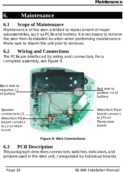
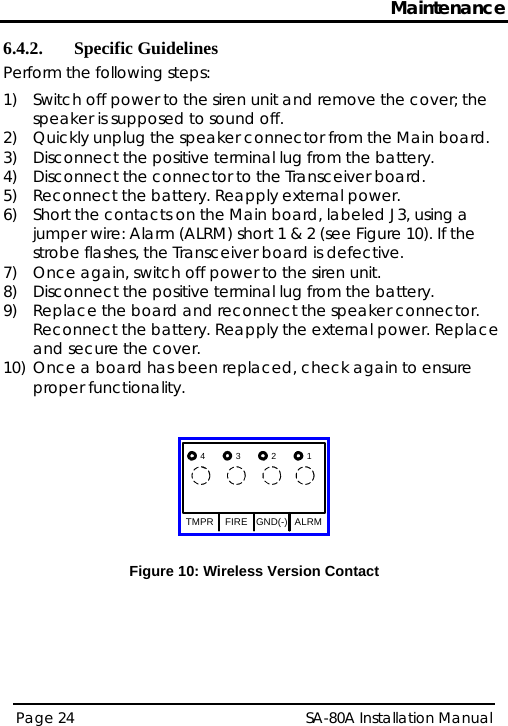
![Introduction Page 3 SA-80A Installation Manual 1. Introduction Rosslare’s SA-80G wireless Siren Annunciator is used in commercial, industrial, and residential locations, either indoors or outdoors. The rugged packaging, styled to fit into any décor, can be mounted on a wall in any direction. This Product must be installed professionally. The siren is capable of providing audible alerts for fire, alarm, and tampering, at levels difficult to ignore. A strong, flashing signal helps to identify the source of the alarm from a distance. • The SA-80G wireless Siren Annunciator includes an RF transceiver module that operates over 433.92 MHz. The SA-80G wireless unit operates with burglar (intrusion) alarm control panels and fire alarm control panels, such as the HomeLogiX, manufactured by Rosslare. It can also operate with Any interference or vandalism, which would be a result of trying to remove the cover from the unit, or tear the unit from the wall, would cause the unit to immediately report such an event by transmitting to the control panel. Priorities for sounding off alarms are according to: 1) Fire 2) Alarm (panic) 3) Tamper Alarms are activated/deactivated from the remote control panel or from any telephone. This product has only one available channel. Pursuant to FCC §15.21 [ 54 FR 17714 , Apr. 25, 1989, as amended at 68 FR 68545 , Dec. 9, 2003], changes or modifications made to equipment, which are not expressly approved by Rosslare Enterprises, Ltd., may void the user's authority to operate the equipment.](https://usermanual.wiki/Rosslare/SA-80G/User-Guide-1201936-Page-5.png)