Rosslare SA-80G SA-80G User Manual SA 80A Installation Manual
Rosslare Enterprises Ltd SA-80G SA 80A Installation Manual
Rosslare >
Users Manual
Wireless Annunciator with Strobe
SA-80G
Installation Manual
June 2009

Introduction
Page 1
SA-80A Installation Manual
Table of Contents
1. Introduction.............................................................. 3
2. Mechanical Description........................................... 4
3. Electrical Description .............................................. 6
3.1 Alarm Operation .................................................. 6
3.2 Self-Check............................................................ 7
3.3 Tamper Operation ................................................ 7
3.4 Wireless Operation............................................... 7
4. Technical Specifications .......................................... 9
5. Installation.............................................................. 11
5.1 Jumper Settings.................................................. 11
5.2 Mechanical Installation...................................... 12
5.3 Testing ............................................................... 17
6. Maintenance ........................................................... 20
6.1 Scope of Maintenance........................................ 20
6.2 Wiring and Connections..................................... 20
6.3 PCB Description ................................................ 20
6.4 Troubleshooting ................................................. 23
Introduction
Appendix A. Limited Warranty................................. 25
Appendix B. Technical Support................................. 27
Note
Upon receipt of your siren annunciator, verify that the siren unit
includes an AC adapter and mounting hardware. If some item(s) is
missing, report the discrepancy to your nearest Rosslare Enterprises
Ltd. Sales office.
Warning!!!
BE SURE TO WEAR PROTECTIVE EAR PLUGS WHILE NEAR THE SIREN.
VERY HIGH SOUND LEVEL MAY CAUSE EAR DAMAGE
Page 2 SA-80A Installation Manual

Introduction
Page 3
SA-80A Installation Manual
1. Introduction
Rosslare’s SA-80G wireless Siren Annunciator is used in commercial,
industrial, and residential locations, either indoors or outdoors. The
rugged packaging, styled to fit into any décor, can be mounted
on a wall in any direction. This Product must be installed
professionally. The siren is capable of providing audible alerts for
fire, alarm, and tampering, at levels difficult to ignore. A strong,
flashing signal helps to identify the source of the alarm from a
distance.
• The SA-80G wireless Siren Annunciator includes an RF
transceiver module that operates over 433.92 MHz.
The SA-80G wireless unit operates with burglar (intrusion) alarm
control panels and fire alarm control panels, such as the
HomeLogiX, manufactured by Rosslare. It can also operate with
Any interference or vandalism, which would be a result of trying to
remove the cover from the unit, or tear the unit from the wall,
would cause the unit to immediately report such an event by
transmitting to the control panel.
Priorities for sounding off alarms are according to:
1) Fire
2) Alarm (panic)
3) Tamper
Alarms are activated/deactivated from the remote control panel
or from any telephone.
This product has only one available channel.
Pursuant to FCC §15.21 [ 54 FR 17714 , Apr. 25, 1989, as amended
at 68 FR 68545 , Dec. 9, 2003], changes or modifications made to
equipment, which are not expressly approved by Rosslare
Enterprises, Ltd., may void the user's authority to operate the
equipment.

Mechanical Description
2. Mechanical Description
The enclosure of the SA-80G is made of sturdy ABS material,
capable of withstanding rain and dust. Sealing grommets on the
mounting holes and around the base render the unit water-
repellent. A transparent grill is used for sound transmission (from
the speaker), and for visual indications.
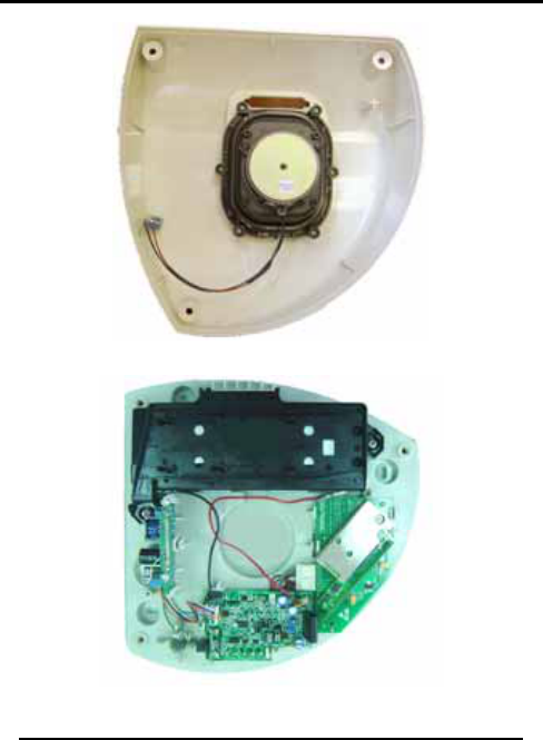
The siren cover holds a strong loudspeaker (see Figure 1). The
base holds three printed circuit assemblies and a back-up battery
(see Figure 2). A fully charged battery powers the unit for over 24
hours, in the event of power failure or disable, and during that
time the battery can power the alarm for at least five minutes.
The PCBs are snapped into place for easy replacement and
secure mounting. A tamper plunger provides switch closure in two
directions:
• Down - If the unit is torn off the wall, the plunger is
released down.
• Up - If the cover is removed from the unit, the plunger
rises.
The PCBs are:
• Main board
• Transceiver board
• Flash board
Warning!!!
High voltage is present on the terminals of the flash tube, when
enabled.
Page 4 SA-80A Installation Manual
Mechanical Description
Figure 1: Cover with Loudspeaker
Figure 2: Base with PCBs
SA-80A Installation Manual Page 5
Electrical Description
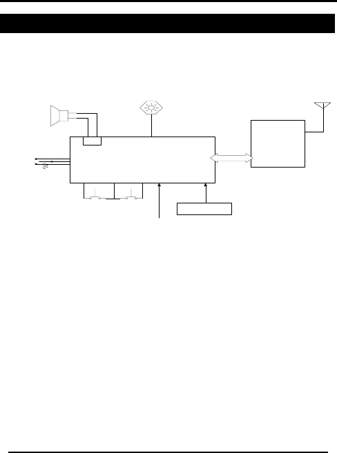
3. Electrical Description
The siren unit (see Figure 3) is basically composed of a Main board
which receives a number of external triggers, and generates
audible and visual indications according to a pre-programmed
microprocessor.
BACK - UP
BATTERY
TRANSCEIVER
PCB
MAIN
BOARD
16 VDC INPUT
TAMPER
SWITCH
STROBE
BOARD
FIRE ALARM
Wired version only
*
Speaker connector
Ground
*
FIRE & ALARM are
relay contacts in the host
panel or switches used
for testing.
Figure 3: Siren Unit Block Diagram
3.1 Alarm Operation
The microprocessor is activated by fire or alarm inputs, and
accordingly generates one of two sound patterns and related
flashing strobe indications:
• Burglar (or panic) alarm sound – the strobe flashes until
the input is restored to normal condition. The speaker in
the siren outputs a loud 1300 to 1800 Hz continuous
sweeping sound, having a 100% duty cycle. The alarm
sounds until the timer runs out (5 or 15 minutes). The
strobe continues to flash, even when the sound has
ceased, until the unit is reset.
• Fire alarm sound – the operation is similar to that of the
burglar alarm, with the exception of the audio sound
from the speaker. The siren sounds off at 800 to 850 Hz,
Page 6 SA-80A Installation Manual

Electrical Description
Page 7
SA-80A Installation Manual
continuously, for a period of 0.5 seconds, and then turns
off for 0.5 seconds. This is repeated three times
altogether, followed by a 1.5 second delay.
3.2 Self-Check
In addition to the alarms, the unit constantly checks itself. Every
four hours, the status of the battery is checked. If the battery is
low, the unit provides continuous visual indications: red LED
indicator flashes at a rate of two seconds on and two seconds off;
two short beeps are generated once per hour.
In the event that main power is removed due to a power failure or
break-in, the normally-illuminated green LED indicator is
extinguished.
3.3 Tamper Operation
The tamper switch is an input to the microprocessor and an
output to the alarm control panel (host). When the switch is
activated, the burglar alarm is generated for five minutes,
regardless of further tamper switch settings. This alarm can be
turned off only by activating the fire or burglar alarm, and then
deactivating it.
The system is armed only 30 seconds after activating and
deactivating the tamper switch function. This is useful for initial
installation and maintenance functions.
3.4 Wireless Operation
As this siren unit is wireless, it has a transceiver PCB. This board
receives/transmits the alarm/tamper/battery status from/to a
remote phone or panel, equipped to interface with the siren at a
distance of up to 200 meters. The board includes a
microprocessor connected to an ASK FM transceiver. An onboard
antenna enables communication to a remote location.

Electrical Description
Page 8 SA-80A Installation Manual
Alarm enabling/disabling is transmitted from the remote panel or
phone, while the tamper/battery status is sent from the siren unit
to the host. Acknowledgements make for reliable
communication.

Technical Specifications
Page 9
SA-80A Installation Manual
4. Technical Specifications
Power Characteristics
Input Voltage: 14-18VDC.
From host panel or wall adapter.
Battery Charging Current: 300 mA max
No alarm
Input Current: 0.6 A; during alarm
Standby: < 100mA; no alarm
Battery Characteristics
Battery Capacity: 2.3 Ahr; 12 V sealed lead-acid
battery
Battery Lifetime: 5 years; typical
Battery Backup: 24 hr min.; in standby mode
Electrical Characteristics
Frequency H model 868.35 MHz; ± 0.1 MHz
Frequency G model 433.92 MHz; ± 0.1 MHz
Effective Transmit Power 10 mW nominal
Transmit Range >180 m
Receiver Sensitivity -100 dBm min.; For 100 kHz
bandwidth

Technical Specifications
Page 10 SA-80A Installation Manual
Siren Output
Speaker Low Level 90 dB; at 1 m
Speaker High Level 103 dB; at 1 m
Environmental Characteristics
Operating Environment: Outdoor Use (IP55)
Operating Temperature: -20°C to +50°C
Operating Humidity: 0% - 95% (Non Condensing)
Dimensions
Height x Width x Depth 25 x 25 x 9 cm
Weight 2236.5 g
Installation
5. Installation
This section provides details and procedures on the physical and
electrical installation of the siren unit. The unit is first physically
installed, and then a number of steps are followed to enable and
arm the device.
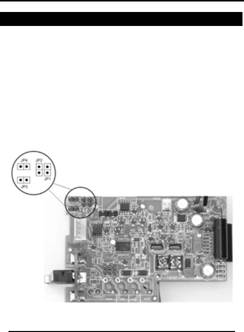
5.1 Jumper Settings
It is recommended to set the jumpers before installing the unit, as
it is much easier than doing so after installation.
1) Disassemble the cover from the base by extracting the three
screws from the cover. Set the screws aside.
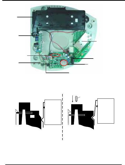
2) Locate the Main board and identify the jumpers to be set,
according to Figure 4 and Table 1.
Figure 4: Setting Jumpers on Main Board
SA-80A Installation Manual Page 11
Installation
Table 1: Main Board Jumper Settings
Jumper Function Fitted Not
Fitted Remarks
JP1 Volume
selection Low High (1)
JP2 Input
topology N.C. N.O. Alarm input
JP3 Alarm
timer 15 min. 5 min.
JP4 Not used For factory
programming
only
Note:
Volume settings are according to section 4 Technical
Specifications.
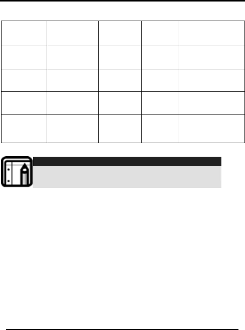
5.2 Mechanical Installation
5.2.1. Preferred Location
Mount the siren unit on a straight surface, away from heat or
exhaust of gases, and preferably in a shady place. The unit is
protected from rain and dust by a gasket surrounding the base of
the unit to seal the cover, and by gaskets that surround each
entry hole in the base (see Figure 5). The unit may be installed in
any one of four directions, as desired by the installer. However, for
the SA-80 G range models, it is recommended to install the unit in
an upright or downright position (as portrayed in Figure 1 and
Figure 6) for optimal RF reception.
Page 12 SA-80A Installation Manual
Installation
Rubber
Gasket for
Tamper
Switch
(+3 places)
Rubber
Gasket for
Mounting
Hole
Figure 5: Base with Sealing Gaskets
5.2.2. Initial Preparation
1) Disassemble the cover from the base by extracting the three
screws from the cover. Set the screws aside.
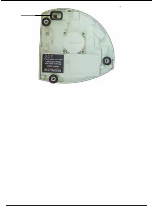
2) Use the dimensions from Figure 6 to locate the three holes to
be drilled in the wall. As an alternative, the base can be
positioned, and the holes marked.
3) Use appropriate hardware to affix the base to the surface.
4) Make sure that the straight side of the base is level.
SA-80A Installation Manual Page 13
Installation
Figure 6: Base Plate Layout
5.2.3. General Wiring Instructions
Before beginning, read the entire process!
1) Remove the Transceiver board from the base, to access the
feed hole for the wires.
Page 14 SA-80A Installation Manual
Installation
2) Locate the feed hole and grommet for the wires to be
connected inside the unit (see Figure 6); two 22 AWG cabling
wires are needed for the 16 VDC power.
3) Use a simple wire loop to pull the cabling through the hole into
the base area. Leave enough slack to make connections to
the Main board.
4) Run the cabling via the rubber grommet, and replace the
grommet in the base.
5) Secure the cabling by using the holding clamp (see Figure 6).
6) Strip the cable and wires and connect the power conductors
to the power input terminals J1 (-16VDC+) (see Figure 7).
Observe polarity!
7) Once all wiring has been done, locate and connect the red
battery wire to the battery positive lug and the black wire to
the negative lug. Do not apply external power at this time.
Note:
The siren is not powered after the battery is connected. The
unit starts operating only after external power from a wall
adapter or from the host panel is applied.
8) Check the operation of the tamper switch, as indicated
hereafter.
5.2.4. Tamper Switch Setting
You can adjust the plunger to compensate for an uneven
mounting surface. You can perform the adjustment using the
screw within the plunger (see Figure 8). Releasing the plunger
activates the micro-switch (alarm condition), until the cover is
replaced.
Reconnect the speaker connector to J5 on the Main board (see
Figure 7), prior to closing the cover.
SA-80A Installation Manual Page 15
Installation
Back-up
Battery
Flash
Board Transceiver
Board
Page 16 SA-80A Installation Manual
Figure 7: Base Assembly Layout
MICROSWITCH
Plunger position with cover
removed.
MICROSWITCH
Adjust the screw in the
plunger until a triangular
slot is obtained; the
microswitch is open.
Press and hold the plunger
while adjusting screw.
Screwdriver
Figure 8: Tamper Switch Plunger Adjustment
Tamper
Switch
Tamper
Switch
Plunger
Speaker
Connector J5 Main Board
Power Input
Terminals

Installation
Page 17
SA-80A Installation Manual
5.3 Testing
It is necessary to check the general operation of the siren, and to
test it after installation and prior to putting it into service.
5.3.1. General Operation
Make sure that power is applied to the siren. Observe that the
green light on the Strobe board is illuminated.
Before beginning, read the entire process!
5.3.2. Testing
The following steps are performed with a telephone unit, type SP-
03, and its remote control; the phone’s frequency is to match that
of the siren.
Perform the steps listed in the table below.
Table 2: Testing Wireless Siren
Step Operation Audio
Indication Visual
Indication
1
Connect power to
the telephone; do
not connect a
phone line.
The phone
emits two
short beeps.
SP03 V1.2 WAIT
2
Enter 8 8 8 8 on the
phone. A beep is
emitted
after each
digit is
entered;
* * * * followed
by,
PROGRAMMING
SELECT
FUNCTION
3 Press the Å key. The phone
emits two
short beeps.
WIRELESS SIRENS
NOT INSTALLED
4 Press Store key. SIREN TIME: 03

Installation
Page 18 SA-80A Installation Manual
5
Press Store key.
WIRELESS SIRENS
followed by
prompt: (Value
1....4 for up to
four sirens on a
system).
6
Enter 1 on the
phone.
WIRELESS SIREN_1
followed by
prompt:
ENROLL
TRANSMIT.
7
Remove the three
screws from the
cover and lift the
cover.
WIRELESS SIREN_1
INSTALLED
For one second
only.
8 Press Escape key 4
times. - Returns to
DISARMED
screen.
9 Press the Panic
button on the
remote control for
3 to 6 seconds.
Wireless
siren is
activated;
internal
alarm in
phone is
activated.
Strobe on
wireless siren is
activated.
10 Press the OFF
pushbutton on the
remote control.
The phone
gives 2 short
beeps.
Returns to
DISARMED
screen.

Installation
Page 19
SA-80A Installation Manual
Wireless
siren is
deactivated
; internal
alarm in
phone is
deactivated
.
Strobe on
wireless siren is
deactivated.
5.3.3. Testing the Tamper Feature
1) Raise the cover of the siren in order to test the tamper feature.
The alarm sounds off immediately (no strobe). Have the
second person turn off the alarm at the host panel.
2) Replace the cover on the base and secure with the three
screws previously removed (see section 5.2.2).
Maintenance
6. Maintenance
6.1 Scope of Maintenance
Maintenance of the siren is limited to replacement of major
subassemblies, such as PCBs and battery. It is necessary to remove
the siren from its installed location when performing maintenance.
Make sure to disarm the unit prior to removal.
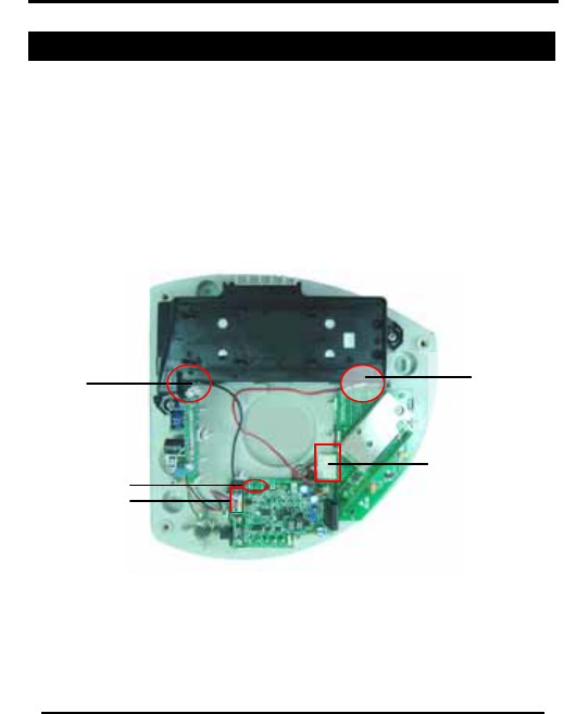
6.2 Wiring and Connections
The PCBs are interfaced by wiring and connectors. For a
complete assembly, see Figure 9.
Black wire to
negative (-)
of battery
Red wire to
positive (+) of
battery
Speaker
connects to J5
Wires from Flash
board connect
to J2 on Main
board
Wires from Main
board connect
to JP2 on
Transceiver
board
Figure 9: Wire Connections
6.3 PCB Description
This paragraph describes connectors, switches, indicators, and
jumpers used in the siren unit, categorized by individual boards.
Page 20 SA-80A Installation Manual

Maintenance
Page 21
SA-80A Installation Manual
6.3.1. Main Board
The Main board includes the major components for the operation
of the siren: a microprocessor, a loudspeaker, driving circuitry, and
a power supply regulator. A number of jumpers are available to
select certain parameters (refer to the table below).
Table 3: Main Board Components
Ref.
Des. Description Function Remarks
J1 Terminal board Input power Pin 1: (+)
Pin 2: (-)
J2 Multi-pin header Strobe
output Pin 1: Strobe +
Pin 2: Strobe -
Pin 3: Power LED
Pin 4: Battery low
out
Pin 5: Ground
J4 Multi-pin header Programmin
g Factory use only
J5 2-pin header Speaker
output
J6 2-pin header Piezzo
output
R16 Potentiometer Float
charge set Factory adjust
only
JP1 Jumper Volume High or low

Maintenance
Page 22 SA-80A Installation Manual
JP2 Jumper Alarm inputs N.C. or N.O.
JP3 Jumper Auto shut-
down 5 or 15 minutes
JP4 Jumper Output
selection Factory use only
SW1 Microswitch Tamper
P1 Plug and wires Connection
s to
Transceiver
board
Pin 1: VBAT
Pin 2: Ground
Pin 3: -
Pin 4: TMPR
Pin 5: PLOWBAT
Pin 6: ALARM
Pin 7: FIRE
Pin 8: PVINDET
6.3.2. Transceiver Board
The Transceiver board includes a transmit/receive chip, a
microprocessor, and a power supply regulator. The only
connector on the board is JP2, used for interconnection to the
Main board. Pin definition matches are given in Table 3, for
connector P1.
Header JP1 is for programming the board, at the factory.

Maintenance
Page 23
SA-80A Installation Manual
6.3.3. Strobe Board
The Strobe board includes a high voltage supply to flash the
strobe bulb during alarms. This board includes two LED indicators
which are visible through the orange plastic, when illuminated.
The indicators are:
• LD1 – A power LED which illuminates when power is
applied.
• D2 – A lo-battery LED which illuminates when battery
voltage is low. This indicator has a cycle of two-seconds
on, and then two-seconds off. It is triggered when the
battery test fails.
A connector plugs into the Main board, at J2; refer to Table 3 for
corresponding pin descriptions.
6.4 Troubleshooting
Troubleshooting of the unit is straightforward. It is assumed that the
unit was installed according to instructions, and was operating
properly. Troubleshooting is done with the unit mounted on the
wall.
6.4.1. General Guidelines
Follow these general guidelines:
• If a problem is reported, verify the operation of the siren
unit by triggering the burglar alarm. Both the speaker and
strobe must operate.
• If only the strobe does not work, the Strobe PCB is faulty.
• If both the Strobe PCB and the Main board do not
function, the problem may be due to the Transceiver PCB
or due to the Main board.
• In all cases, check for a speaker impedance of four ohms.
Maintenance
6.4.2. Specific Guidelines
Perform the following steps:
1) Switch off power to the siren unit and remove the cover; the
speaker is supposed to sound off.
2) Quickly unplug the speaker connector from the Main board.
3) Disconnect the positive terminal lug from the battery.
4) Disconnect the connector to the Transceiver board.
5) Reconnect the battery. Reapply external power.
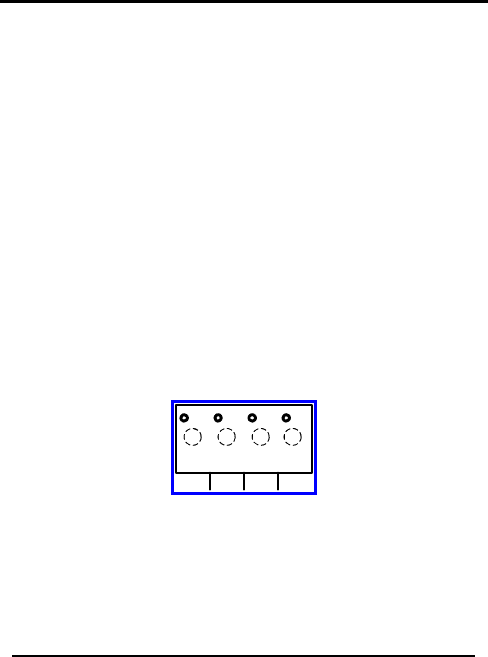
6) Short the contacts on the Main board, labeled J3, using a
jumper wire: Alarm (ALRM) short 1 & 2 (see Figure 10). If the
strobe flashes, the Transceiver board is defective.
7) Once again, switch off power to the siren unit.
8) Disconnect the positive terminal lug from the battery.
9) Replace the board and reconnect the speaker connector.
Reconnect the battery. Reapply the external power. Replace
and secure the cover.
10) Once a board has been replaced, check again to ensure
proper functionality.
TMPR FIRE GND(-) ALRM
4321
Figure 10: Wireless Version Contact
Page 24 SA-80A Installation Manual

Limited Warranty
Page 25
SA-80A Installation Manual
Appendix A. Limited Warranty
ROSSLARE ENTERPRISES LIMITED S (Rosslare) TWO YEARS LIMITED WARRANTY
is applicable worldwide. This warranty supersedes any other warranty. Rosslare's TWO
YEARS LIMITED WARRANTY is subject to the following conditions:
Warranty
Warranty of Rosslare's products extends to the original purchaser (Customer) of the
Rosslare product and is not transferable.
Products Covered By This Warranty and Duration
ROSSLARE ENTERPRISES LTD. AND / ORSUBSIDIARIES (ROSSLARE) warrants that
the SA-80G Wireless Annunciator Siren, to be free from defects in materials and assembly
in the course of normal use and service. The warranty period commences with the date of
shipment to the original purchaser and extends for a period of 2 years (24 Months).
Warranty Remedy Coverage
In the event of a breach of warranty, ROSSLARE will credit Customer with the price of the
Product paid by Customer, provided that the warranty claim is delivered to ROSSLARE by
the Customer during the warranty period in accordance with the terms of this warranty.
Unless otherwise requested by ROSSLARE ENTERPRISES LTD. AND / OR
SUBSIDIARIES representative, return of the failed product(s) is not immediately required.
If ROSSLARE has not contacted the Customer within a sixty (60) day holding period
following the delivery of the warranty claim, Customer will not be required to return the
failed product(s). All returned Product(s), as may be requested at ROSSLARE
ENTERPRISES LTD. AND /OR SUBSIDIARY’S sole discretion, shall become the property
of ROSSLARE ENTERPRISES LTD. AND /OR SUBSIDIARIES.
To exercise the warranty, the user must contact Rosslare Enterprises Ltd. to obtain an
RMA number after which, the product must be returned to the Manufacturer freight prepaid
and insured
In the event ROSSLARE chooses to perform a product evaluation within the sixty (60) day
holding period and no defect is found, a minimum US$ 50.00 or equivalent charge will be
applied to each Product for labor required in the evaluation.
Rosslare will repair or replace, at its discretion, any product that under normal conditions
of use and service proves to be defective in material or workmanship. No charge will be
applied for labor or parts with respect to defects covered by this warranty, provided that
the work is done by Rosslare or a Rosslare authorized service center.

Limited Warranty
Page 26 SA-80A Installation Manual
Exclusions and Limitations
ROSSLARE shall not be responsible or liable for any damage or loss resulting from the
operation or performance of any Product or any systems in which a Product is
incorporated. This warranty shall not extend to any ancillary equipment not furnished by
ROSSLARE, which is attached to or used in conjunction with a Product, nor to any Product
that is used with any ancillary equipment, which is not furnished by ROSSLARE.
This warranty does not cover expenses incurred in the transportation, freight cost to the
repair center, removal or reinstallation of the product, whether or not proven defective.
Specifically excluded from this warranty are any failures resulting from Customer's
improper testing, operation, installation, or damage resulting from use of the Product in
other than its normal and customary manner, or any maintenance, modification, alteration,
or adjustment or any type of abuse, neglect, accident, misuse, improper operation, normal
wear, defects or damage due to lightning or other electrical discharge. This warranty does
not cover repair or replacement where normal use has exhausted the life of a part or
instrument, or any modification or abuse of, or tampering with, the Product if Product
disassembled or repaired in such a manner as to adversely affect performance or prevent
adequate inspection and testing to verify any warranty claim.
ROSSLARE does not warrant the installation, maintenance, or service of the Product.
Service life of the product is dependent upon the care it receives and the conditions under
which it has to operate.
In no event shall Rosslare be liable for incidental or consequential damages.
Limited Warranty Terms
THIS WARRANTY SETS FORTH THE FULL EXTENT OF ROSSLARE ENTERPRISES LTD. AND
ITS SUBSIDIARIES’ WARRANTY
THE TERMS OF THIS WARRANTY MAY NOT BE VARIED BY ANY PERSON, WHETHER OR
NOT PURPORTING TO REPRESENT OR ACT ON BEHALF OF ROSSLARE.
THIS LIMITED WARRANTY IS PROVIDED IN LIEU OF ALL OTHER WARRANTIES. ALL OTHER
WARRANTIES EXPRESSED OR IMPLIED, INCLUDING WITHOUT LIMITATION, IMPLIED
WARRANTIES OF MERCHANTABILITY AND FITNESS FOR A PARTICULAR PURPOSE, ARE
SPECIFICALLY EXCLUDED.
IN NO EVENT SHALL ROSSLARE BE LIABLE FOR DAMAGES IN EXCESS OF THE
PURCHASE PRICE OF THE PRODUCT, OR FOR ANY OTHER INCIDENTAL,
CONSEQUENTIAL OR SPECIAL DAMAGES, INCLUDING BUT NOT LIMITED TO LOSS OF
USE, LOSS OF TIME, COMMERCIAL LOSS, INCONVENIENCE, AND LOSS OF PROFITS,
ARISING OUT OF THE INSTALLATION, USE, OR INABILITY TO USE SUCH PRODUCT, TO
THE FULLEST EXTENT THAT ANY SUCH LOSS OR DAMAGE MAY BE DISCLAIMED BY LAW.
THIS WARRANTY SHALL BECOME NULL AND VOID IN THE EVENT OF A VIOLATION OF THE
PROVISIONS OF THIS LIMITED WARRANTY.

Technical Support
Page 27
SA-80A Installation Manual
Appendix B. Technical Support
Asia Pacific, Middle East
Rosslare Security Products Headquarters
905-912 Wing Fat Industrial Bldg,
12 Wang Tai Road,
Kowloon Bay Hong Kong
Tel: +852 2795-5630
Fax: +852 2795-1508
E-mail: support.apac@rosslaresecurity.com
United States and Canada
1600 Hart Court, Suite 103
Southlake, TX, USA 76092
Tool Free:+1-866-632-1101
Local:+1-817-305-0006
Fax: +1-817-305-0069
E-mail: support.na@rosslaresecurity.com
Europe, Africa
Global Technical Support & Training Center
HaMelecha 22
Rosh HaAyin, Israel 48091
Tel: +972 3 938-6838
Fax: +972 3 938-6830
E-mail: support.eu@rosslaresecurity.com
South America
Pringles 868, 1640 Martinez
Buenos Aires
Argentina
Tel: +54 11 4798-0095
Fax: +54 11 4798-2228
Web Site: www.rosslaresecurity.com

0706-0960236+01
www.rosslaresecurity.com