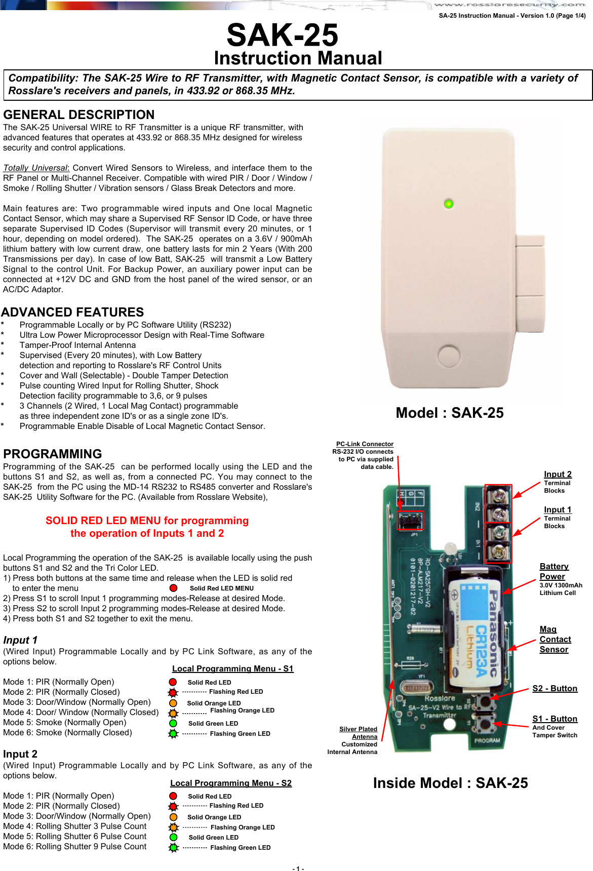
Rosslare SA25G Wired to RF Transmitter User Manual Visio SA 25 Instruction Manual 28 01 04 A4 vsd
Rosslare Enterprises Ltd Wired to RF Transmitter Visio SA 25 Instruction Manual 28 01 04 A4 vsd
Rosslare >
Contents
- 1. User Manual Part 1
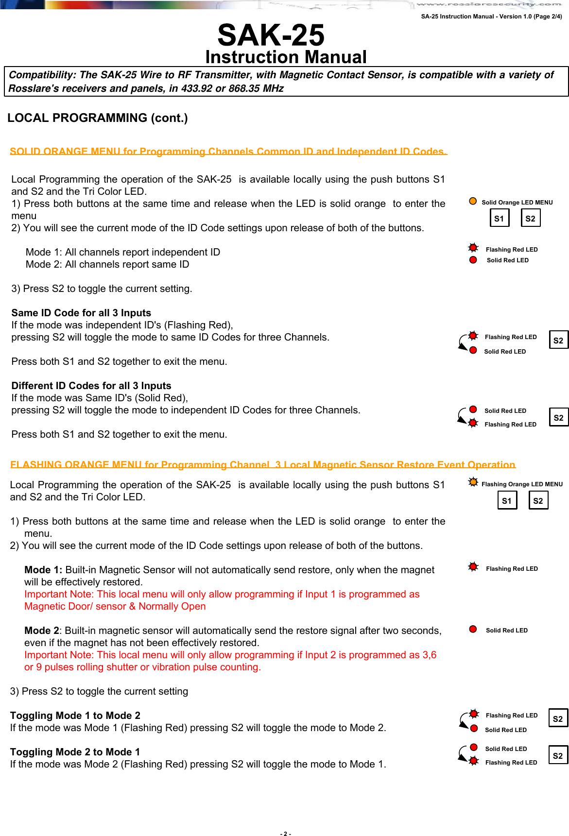
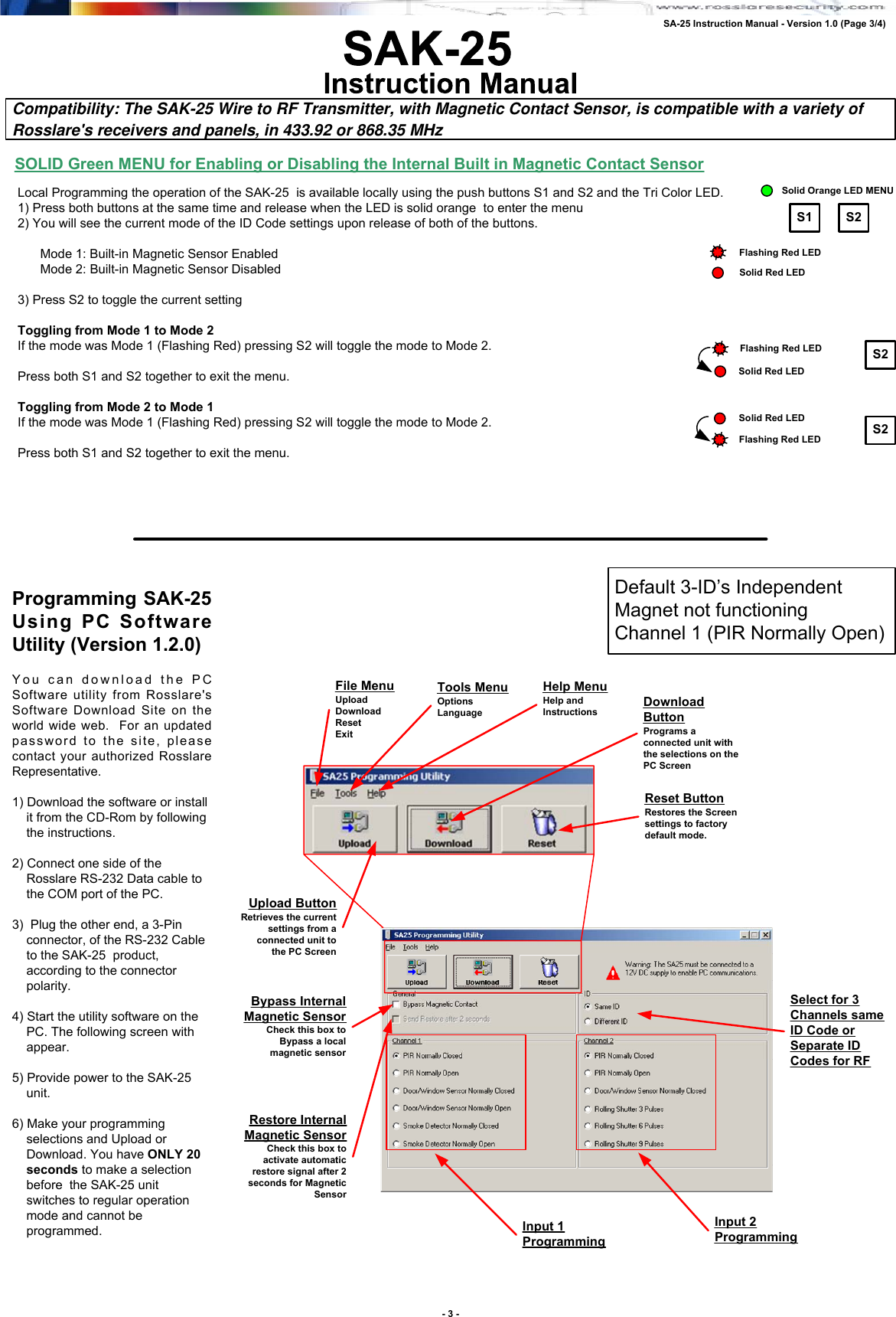
- 2. User Manual Part 2
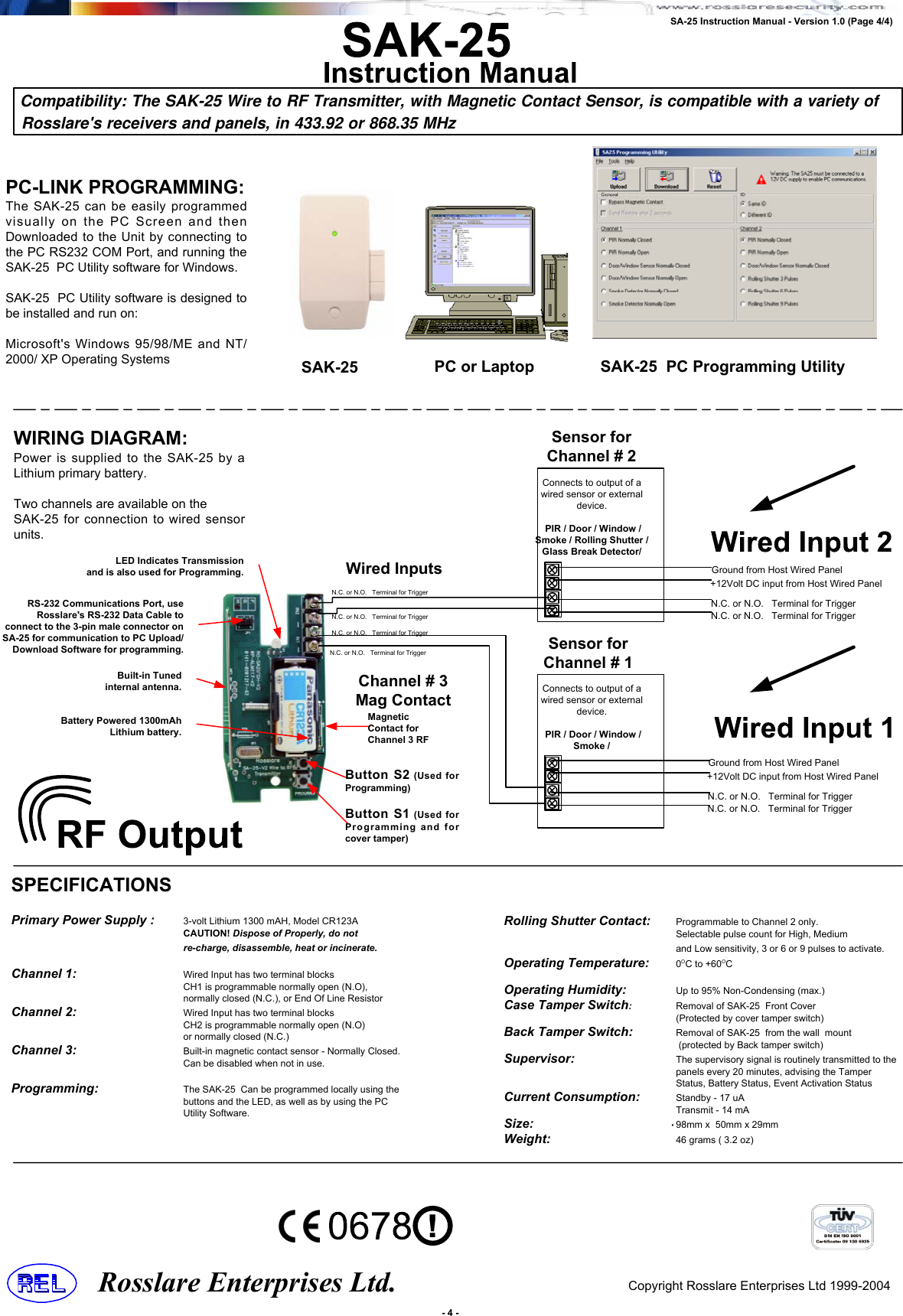
User Manual Part 2