Rosslare SA25G Wired to RF Transmitter User Manual Visio SA 25 Instruction Manual 28 01 04 A4 vsd
Rosslare Enterprises Ltd Wired to RF Transmitter Visio SA 25 Instruction Manual 28 01 04 A4 vsd
Rosslare >
Contents
- 1. User Manual Part 1
- 2. User Manual Part 2
User Manual Part 2
Compatibility: The SAK-25 Wire to RF Transmitter, with Magnetic Contact Sensor, is compatible with a variety of
Rosslare's receivers and panels, in 433.92 or 868.35 MHz.
Model : SAK-25
ADVANCED FEATURES
*Programmable Locally or by PC Software Utility (RS232)
*Ultra Low Power Microprocessor Design with Real-Time Software
*Tamper-Proof Internal Antenna
*Supervised (Every 20 minutes), with Low Battery
detection and reporting to Rosslare's RF Control Units
*Cover and Wall (Selectable) - Double Tamper Detection
*Pulse counting Wired Input for Rolling Shutter, Shock
Detection facility programmable to 3,6, or 9 pulses
*3 Channels (2 Wired, 1 Local Mag Contact) programmable
as three independent zone ID's or as a single zone ID's.
*Programmable Enable Disable of Local Magnetic Contact Sensor.
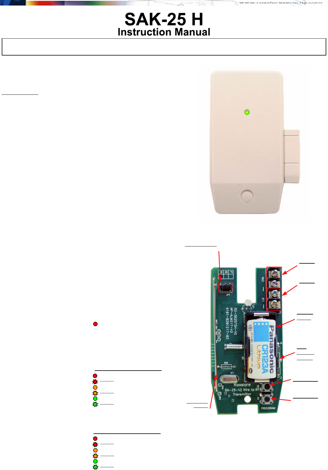
Inside Model : SAK-25
GENERAL DESCRIPTION
The SAK-25 Universal WIRE to RF Transmitter is a unique RF transmitter, with
advanced features that operates at 433.92 or 868.35 MHz designed for wireless
security and control applications.
Totally Universal: Convert Wired Sensors to Wireless, and interface them to the
RF Panel or Multi-Channel Receiver. Compatible with wired PIR / Door / Window /
Smoke / Rolling Shutter / Vibration sensors / Glass Break Detectors and more.
Main features are: Two programmable wired inputs and One local Magnetic
Contact Sensor, which may share a Supervised RF Sensor ID Code, or have three
separate Supervised ID Codes (Supervisor will transmit every 20 minutes, or 1
hour, depending on model ordered). The SAK-25 operates on a 3.6V / 900mAh
lithium battery with low current draw, one battery lasts for min 2 Years (With 200
Transmissions per day). In case of low Batt, SAK-25 will transmit a Low Battery
Signal to the control Unit. For Backup Power, an auxiliary power input can be
connected at +12V DC and GND from the host panel of the wired sensor, or an
AC/DC Adaptor.
PROGRAMMING
Programming of the SAK-25 can be performed locally using the LED and the
buttons S1 and S2, as well as, from a connected PC. You may connect to the
SAK-25 from the PC using the MD-14 RS232 to RS485 converter and Rosslare's
SAK-25 Utility Software for the PC. (Available from Rosslare Website),
Local Programming the operation of the SAK-25 is available locally using the push
buttons S1 and S2 and the Tri Color LED.
1) Press both buttons at the same time and release when the LED is solid red
to enter the menu
2) Press S1 to scroll Input 1 programming modes-Release at desired Mode.
3) Press S2 to scroll Input 2 programming modes-Release at desired Mode.
4) Press both S1 and S2 together to exit the menu.
Input 1
(Wired Input) Programmable Locally and by PC Link Software, as any of the
options below.
Mode 1: PIR (Normally Open)
Mode 2: PIR (Normally Closed)
Mode 3: Door/Window (Normally Open)
Mode 4: Door/ Window (Normally Closed)
Mode 5: Smoke (Normally Open)
Mode 6: Smoke (Normally Closed)
Input 2
(Wired Input) Programmable Locally and by PC Link Software, as any of the
options below.
Mode 1: PIR (Normally Open)
Mode 2: PIR (Normally Closed)
Mode 3: Door/Window (Normally Open)
Mode 4: Rolling Shutter 3 Pulse Count
Mode 5: Rolling Shutter 6 Pulse Count
Mode 6: Rolling Shutter 9 Pulse Count
SOLID RED LED MENU for programming
the operation of Inputs 1 and 2
Solid Red LED
Flashing Red LED
Solid Orange LED
Flashing Orange LED
Solid Green LED
Flashing Green LED
Local Programming Menu - S1
Solid Red LED
Flashing Red LED
Solid Orange LED
Flashing Orange LED
Solid Green LED
Flashing Green LED
Local Programming Menu - S2
Solid Red LED MENU
Input 2
Terminal
Blocks
Battery
Power
3.0V 1300mAh
Lithium Cell
S2 - Button
S1 - Button
And Cover
Tamper Switch
Silver Plated
Antenna
Customized
Internal Antenna
PC-Link Connector
RS-232 I/O connects
to PC via supplied
data cable.
Mag
Contact
Sensor
Input 1
Terminal
Blocks
- 1 -
SA-25 Instruction Manual - Version 1.0 (Page 1/4)
Compatibility: The SAK-25 Wire to RF Transmitter, with Magnetic Contact Sensor, is compatible with a variety of
Rosslare's receivers and panels, in 433.92 or 868.35 MHz
- 2 -
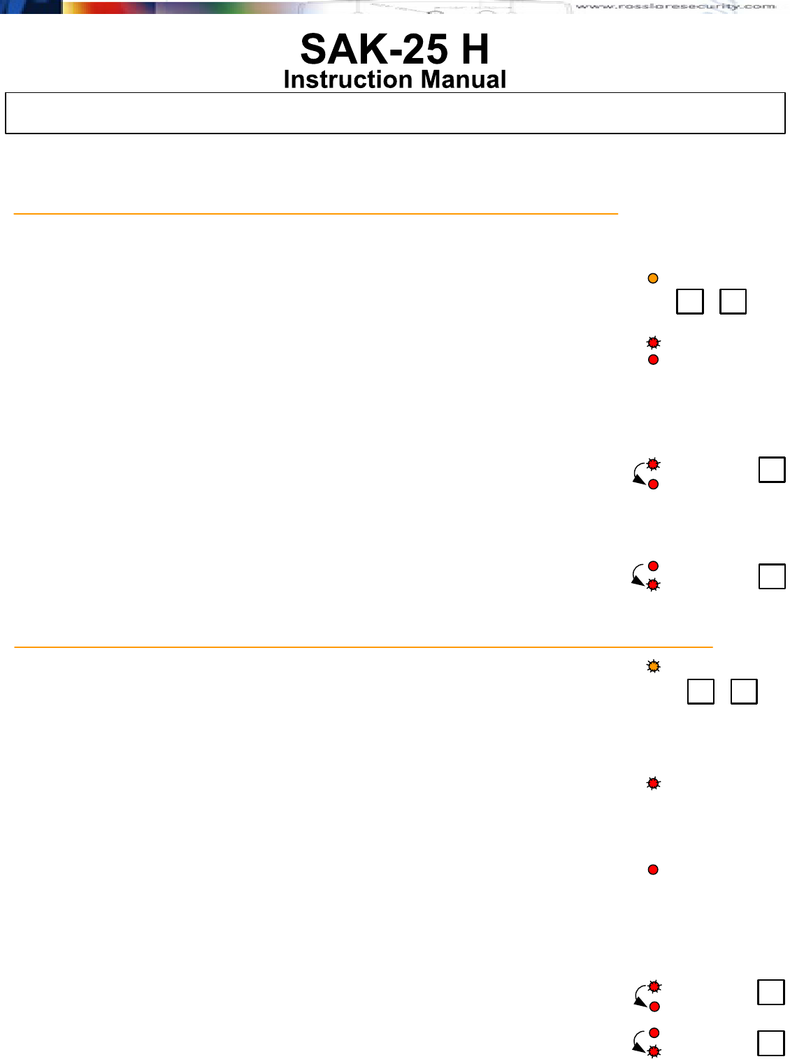
Local Programming the operation of the SAK-25 is available locally using the push buttons S1
and S2 and the Tri Color LED.
1) Press both buttons at the same time and release when the LED is solid orange to enter the
menu
2) You will see the current mode of the ID Code settings upon release of both of the buttons.
Mode 1: All channels report independent ID
Mode 2: All channels report same ID
3) Press S2 to toggle the current setting.
Same ID Code for all 3 Inputs
If the mode was independent ID's (Flashing Red),
pressing S2 will toggle the mode to same ID Codes for three Channels.
Press both S1 and S2 together to exit the menu.
Different ID Codes for all 3 Inputs
If the mode was Same ID's (Solid Red),
pressing S2 will toggle the mode to independent ID Codes for three Channels.
Press both S1 and S2 together to exit the menu.
SOLID ORANGE MENU for Programming Channels Common ID and Independent ID Codes.
S2
S2
Solid Red LED
Flashing Red LED
Solid Red LED
Flashing Red LED
Solid Red LED
Flashing Red LED
Solid Orange LED MENU
S2S1
LOCAL PROGRAMMING (cont.)
Local Programming the operation of the SAK-25 is available locally using the push buttons S1
and S2 and the Tri Color LED.
1) Press both buttons at the same time and release when the LED is solid orange to enter the
menu.
2) You will see the current mode of the ID Code settings upon release of both of the buttons.
Mode 1: Built-in Magnetic Sensor will not automatically send restore, only when the magnet
will be effectively restored.
Important Note: This local menu will only allow programming if Input 1 is programmed as
Magnetic Door/ sensor & Normally Open
Mode 2: Built-in magnetic sensor will automatically send the restore signal after two seconds,
even if the magnet has not been effectively restored.
Important Note: This local menu will only allow programming if Input 2 is programmed as 3,6
or 9 pulses rolling shutter or vibration pulse counting.
3) Press S2 to toggle the current setting
Toggling Mode 1 to Mode 2
If the mode was Mode 1 (Flashing Red) pressing S2 will toggle the mode to Mode 2.
Toggling Mode 2 to Mode 1
If the mode was Mode 2 (Flashing Red) pressing S2 will toggle the mode to Mode 1.
FLASHING ORANGE MENU for Programming Channel 3 Local Magnetic Sensor Restore Event Operation
Flashing Orange LED MENU
S2S1
Solid Red LED
Flashing Red LED
S2
S2
Solid Red LED
Flashing Red LED
Solid Red LED
Flashing Red LED
SA-25 Instruction Manual - Version 1.0 (Page 2/4)
Compatibility: The SAK-25 Wire to RF Transmitter, with Magnetic Contact Sensor, is compatible with a variety of
Rosslare's receivers and panels, in 433.92 or 868.35 MHz
Default 3-ID’s Independent
Magnet not functioning
Channel 1 (PIR Normally Open)
- 3 -
Local Programming the operation of the SAK-25 is available locally using the push buttons S1 and S2 and the Tri Color LED.
1) Press both buttons at the same time and release when the LED is solid orange to enter the menu
2) You will see the current mode of the ID Code settings upon release of both of the buttons.
Mode 1: Built-in Magnetic Sensor Enabled
Mode 2: Built-in Magnetic Sensor Disabled
3) Press S2 to toggle the current setting
Toggling from Mode 1 to Mode 2
If the mode was Mode 1 (Flashing Red) pressing S2 will toggle the mode to Mode 2.
Press both S1 and S2 together to exit the menu.
Toggling from Mode 2 to Mode 1
If the mode was Mode 1 (Flashing Red) pressing S2 will toggle the mode to Mode 2.
Press both S1 and S2 together to exit the menu.
SOLID Green MENU for Enabling or Disabling the Internal Built in Magnetic Contact Sensor
Solid Orange LED MENU
S2S1
Solid Red LED
Flashing Red LED
S2
S2
Solid Red LED
Flashing Red LED
Solid Red LED
Flashing Red LED
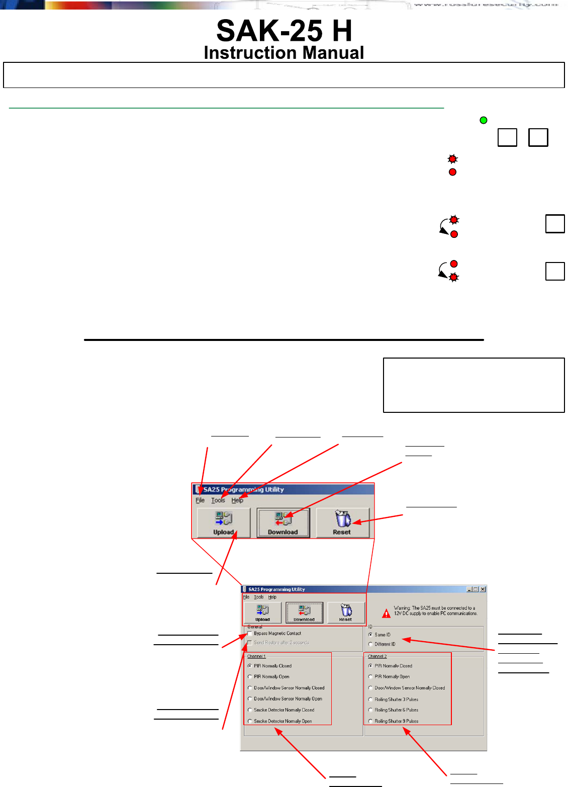
Bypass Internal
Magnetic Sensor
Check this box to
Bypass a local
magnetic sensor
Restore Internal
Magnetic Sensor
Check this box to
activate automatic
restore signal after 2
seconds for Magnetic
Sensor
Input 1
Programming
Input 2
Programming
Select for 3
Channels same
ID Code or
Separate ID
Codes for RF
Upload Button
Retrieves the current
settings from a
connected unit to
the PC Screen
Tools Menu
Options
Language
Help Menu
Help and
Instructions
File Menu
Upload
Download
Reset
Exit
Download
Button
Programs a
connected unit with
the selections on the
PC Screen
Reset Button
Restores the Screen
settings to factory
default mode.
Programming SAK-25
Using PC Software
Utility (Version 1.2.0)
You can download the PC
Software utility from Rosslare's
Software Download Site on the
world wide web. For an updated
password to the site, please
contact your authorized Rosslare
Representative.
1) Download the software or install
it from the CD-Rom by following
the instructions.
2) Connect one side of the
Rosslare RS-232 Data cable to
the COM port of the PC.
3) Plug the other end, a 3-Pin
connector, of the RS-232 Cable
to the SAK-25 product,
according to the connector
polarity.
4) Start the utility software on the
PC. The following screen with
appear.
5) Provide power to the SAK-25
unit.
6) Make your programming
selections and Upload or
Download. You have ONLY 20
seconds to make a selection
before the SAK-25 unit
switches to regular operation
mode and cannot be
programmed.
SA-25 Instruction Manual - Version 1.0 (Page 3/4)
Compatibility: The SAK-25 Wire to RF Transmitter, with Magnetic Contact Sensor, is compatible with a variety of
Rosslare's receivers and panels, in 433.92 or 868.35 MHz
SPECIFICATIONS
Primary Power Supply : 3-volt Lithium 1300 mAH, Model CR123A
CAUTION! Dispose of Properly, do not
re-charge, disassemble, heat or incinerate.
Channel 1: Wired Input has two terminal blocks
CH1 is programmable normally open (N.O),
normally closed (N.C.), or End Of Line Resistor
Channel 2: Wired Input has two terminal blocks
CH2 is programmable normally open (N.O)
or normally closed (N.C.)
Channel 3: Built-in magnetic contact sensor - Normally Closed.
Can be disabled when not in use.
Programming: The SAK-25 Can be programmed locally using the
buttons and the LED, as well as by using the PC
Utility Software.
Rolling Shutter Contact: Programmable to Channel 2 only.
Selectable pulse count for High, Medium
and Low sensitivity, 3 or 6 or 9 pulses to activate.
Operating Temperature: 0OC to +60OC
Operating Humidity: Up to 95% Non-Condensing (max.)
Case Tamper Switch:Removal of SAK-25 Front Cover
(Protected by cover tamper switch)
Back Tamper Switch: Removal of SAK-25 from the wall mount
(protected by Back tamper switch)
Supervisor: The supervisory signal is routinely transmitted to the
panels every 20 minutes, advising the Tamper
Status, Battery Status, Event Activation Status
Current Consumption: Standby - 17 uA
Transmit - 14 mA
Size: 98mm x 50mm x 29mm
Weight: 46 grams ( 3.2 oz)
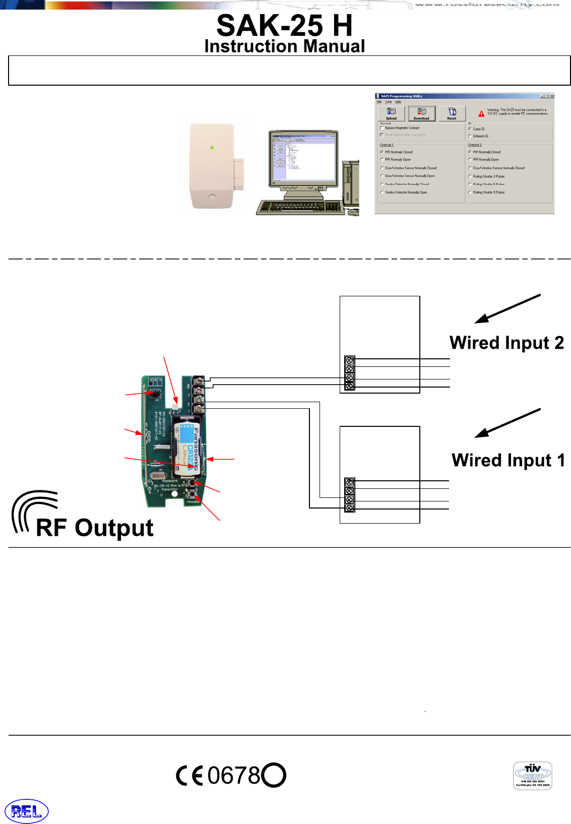
PC-LINK PROGRAMMING:
The SAK-25 can be easily programmed
visually on the PC Screen and then
Downloaded to the Unit by connecting to
the PC RS232 COM Port, and running the
SAK-25 PC Utility software for Windows.
SAK-25 PC Utility software is designed to
be installed and run on:
Microsoft's Windows 95/98/ME and NT/
2000/ XP Operating Systems SAK-25 PC Programming UtilityPC or Laptop
SAK-25
- 4 -
Magnetic
Contact for
Channel 3 RF
LED Indicates Transmission
and is also used for Programming.
Battery Powered 1300mAh
Lithium battery.
Button S1 (Used for
Programming and for
cover tamper)
Built-in Tuned
internal antenna.
Connects to output of a
wired sensor or external
device.
PIR / Door / Window /
Smoke / Rolling Shutter /
Glass Break Detector/
+12Volt DC input from Host Wired Panel
N.C. or N.O. Terminal for Trigger
N.C. or N.O. Terminal for Trigger
Ground from Host Wired Panel
N.C. or N.O. Terminal for Trigger
Sensor for
Channel # 2
Connects to output of a
wired sensor or external
device.
PIR / Door / Window /
Smoke /
Sensor for
Channel # 1
N.C. or N.O. Terminal for Trigger
N.C. or N.O. Terminal for Trigger
N.C. or N.O. Terminal for Trigger
Channel # 3
Mag Contact
Wired Inputs
Button S2 (Used for
Programming)
RS-232 Communications Port, use
Rosslare's RS-232 Data Cable to
connect to the 3-pin male connector on
SA-25 for communication to PC Upload/
Download Software for programming.
WIRING DIAGRAM:
Power is supplied to the SAK-25 by a
Lithium primary battery.
Two channels are available on the
SAK-25 for connection to wired sensor
units.
+12Volt DC input from Host Wired Panel
N.C. or N.O. Terminal for Trigger
N.C. or N.O. Terminal for Trigger
Ground from Host Wired Panel
!
Copyright Rosslare Enterprises Ltd 1999-2004
Rosslare Enterprises Ltd.
SA-25 Instruction Manual - Version 1.0 (Page 4/4)