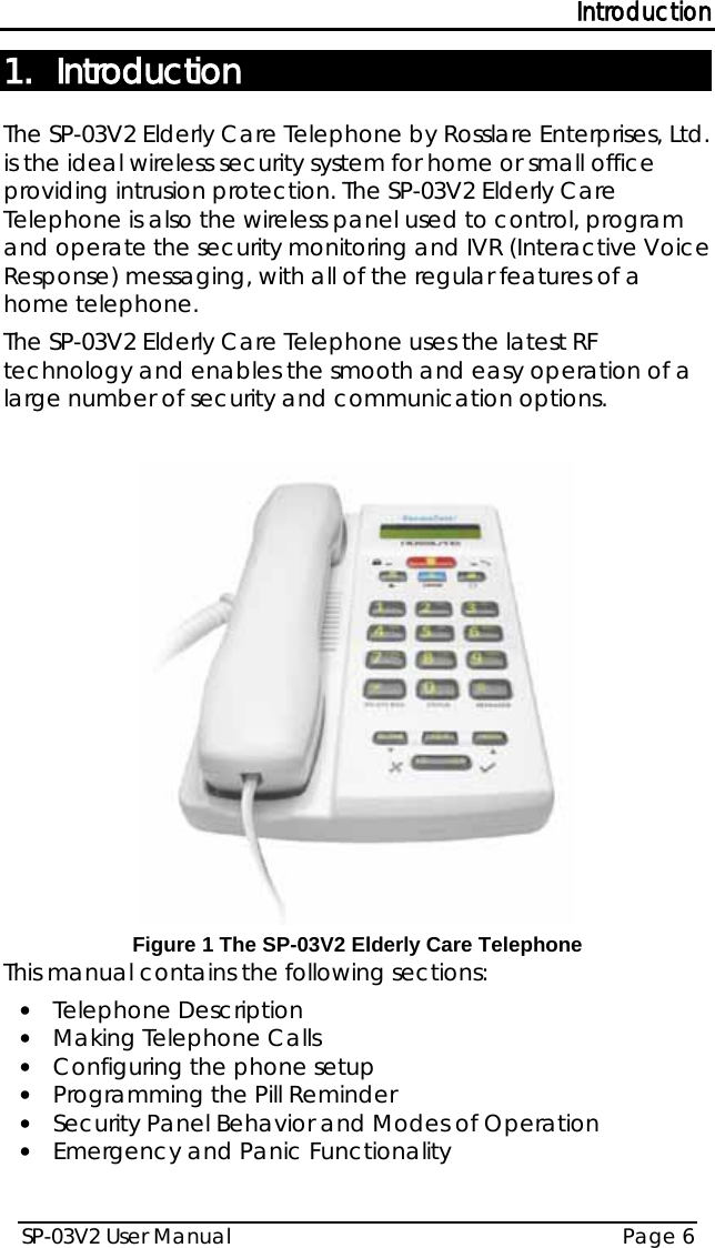
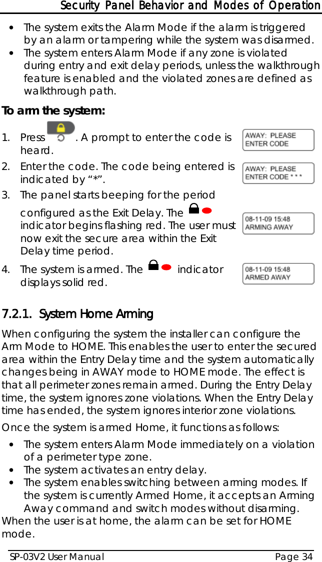
Rosslare SP-03V2G Professional Wireless Elderly Assist combined with alarm system User Manual SP 03V2
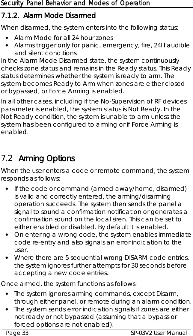
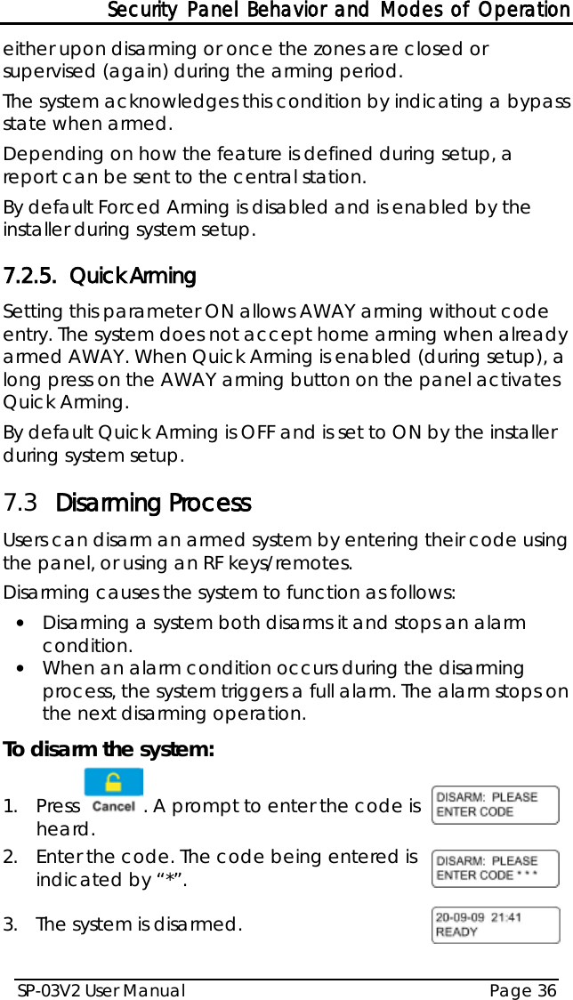
Rosslare Enterprises Ltd Professional Wireless Elderly Assist combined with alarm system SP 03V2
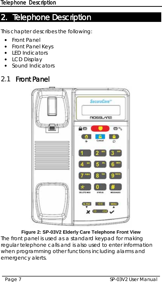
Rosslare >
Contents
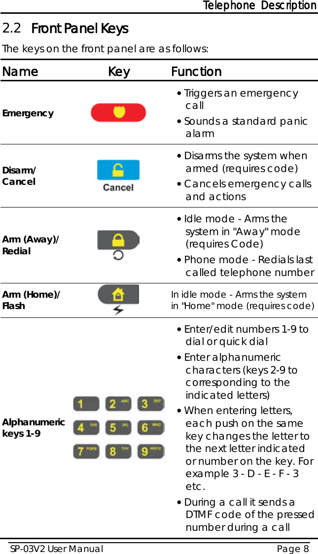
- 1. inst guide
- 2. manual
manual