Rosslare SP-N6G HomeLogiX User Manual HomeLogiX Installer Manual
Rosslare Enterprises Ltd HomeLogiX HomeLogiX Installer Manual
UserManual.wiki
>
Rosslare
>
SP-N6G User Manual
>
Users Manual II
Contents
1.
Users Manual I
2.
Users Manual II
Users Manual II
Navigation menu
Upload a User Manual
Namespaces
Wiki Guide
HTML
PDF
Info
Views
User Manual
Discussion / Help
Navigation
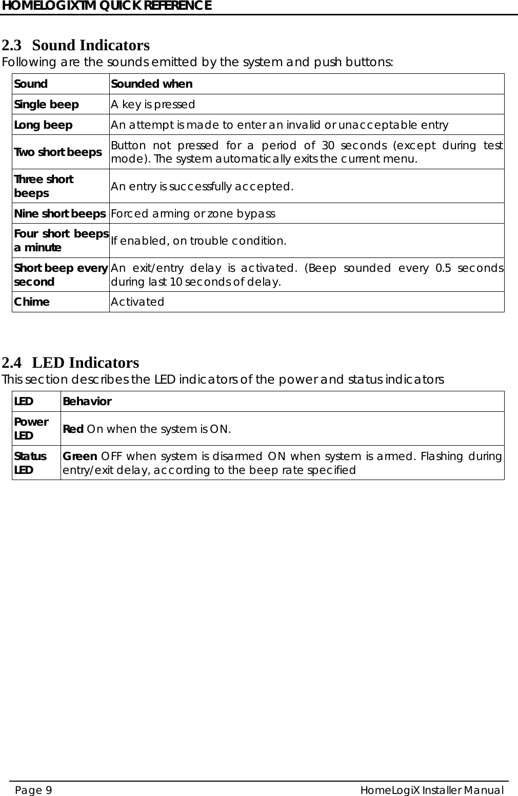
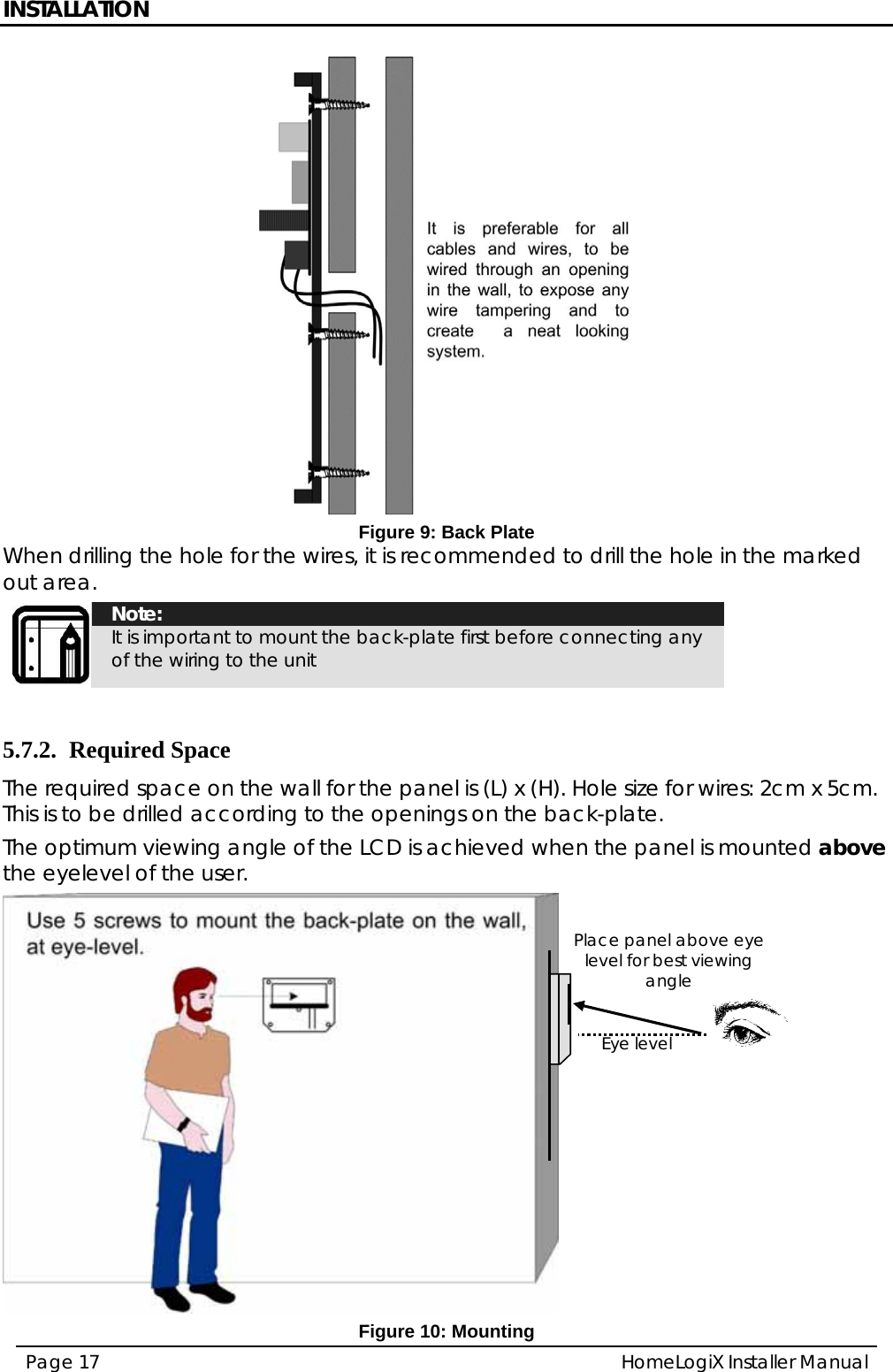
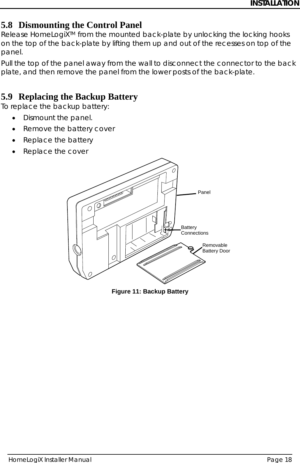
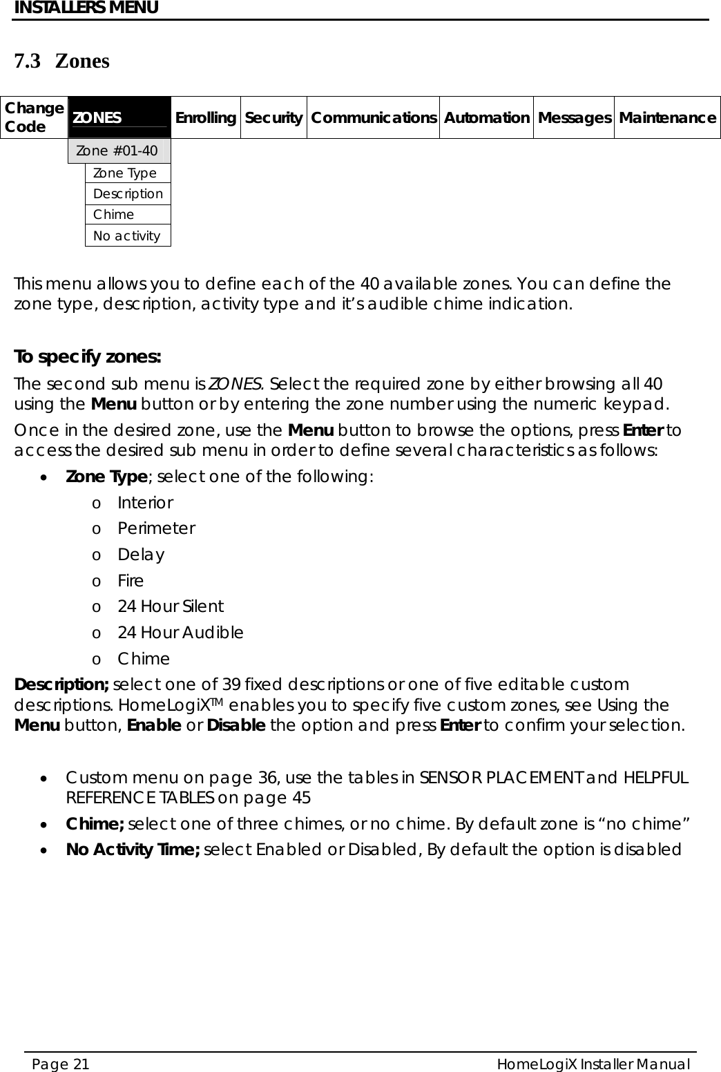
![INTRODUCTION HomeLogiX Installer Manual Page 5 1. INTRODUCTION 1.1 General The HomeLogiXTM panel by Rosslare is the perfect wireless security system for intrusion protection of the home, or small office providing security monitoring and VIP Voice messaging. Users receive the latest RF technology in a wide selection of advanced wireless sensors and remotes, and benefit from smooth and easy operation of a large number of security and communication options. The HomeLogiXTM panel, while easy to install and set up, must be installed professionally via local programming and via direct or modem connection to a PC running the HomeLogiXTM PC Software. The Panel has two full split reporting features for communicating to central station for Contact ID + 2-Way Voice Enabled event reporting and vocal communications. This product has only one available channel. VIP features include Voice Assist, where the panel uses voice to prompt the user, Private Messaging to three destinations, with an optional 2-way voice session for every message. 1.2 Special Features • 40 zones – 39 wireless zones, 1 wired zone and tamper • Supports 8 remote controls, 4 sirens and 4 wireless keypads • Programmable remote-control buttons • Interactive telephone voice menu (Voice interactive system) • Flexible PGM automation features • Five Custom textual and recordable zone descriptions • Advanced testing and diagnostics options • Remote (telephone) two-way voice and listen-in • Programmable No Activity timer (Version 2.0 and up) 1.3 Information to User Pursuant to FCC §15.21 [ 54 FR 17714 , Apr. 25, 1989, as amended at 68 FR 68545 , Dec. 9, 2003], changes or modifications made to equipment, which are not expressly approved by Rosslare Enterprises, Ltd., may void the user's authority to operate the equipment.](https://usermanual.wiki/Rosslare/SP-N6G.Users-Manual-II/User-Guide-1201320-Page-6.png)