Rosslare SP-N6G HomeLogiX User Manual HomeLogiX Installer Manual
Rosslare Enterprises Ltd HomeLogiX HomeLogiX Installer Manual
Rosslare >
Contents
- 1. Users Manual I
- 2. Users Manual II
Users Manual II
SPN6G (HLX40)
Advanced Wireless Security Panel
Installation Manual
May 2009

Table of Contents
HomeLogiX Installer Manual Page ii
Table of Contents
1. INTRODUCTION.....................................................................................................5
1.1 General.............................................................................................................................5
1.2 Special Features ..............................................................................................................5
1.3 Information to User ........................................................................................................5
2. HOMELOGIXTM QUICK REFERENCE................................................................6
2.1 The Panel .........................................................................................................................6
2.2 The Keypad .....................................................................................................................7
2.2.1. Keypad Operated Functions........................................................................................................................8
2.3 Sound Indicators.............................................................................................................9
2.4 LED Indicators................................................................................................................9
3. SPECIFICATIONS ................................................................................................10
3.1 RF Data..........................................................................................................................10
3.2 Environmental Data .....................................................................................................10
3.3 Electrical Data...............................................................................................................10
3.4 Communication.............................................................................................................11
4. USER MENU STRUCTURE .................................................................................12
5. INSTALLATION ....................................................................................................13
5.1 Unpacking the Equipment ...........................................................................................13
5.1.1. HomeLogiXTM Package Content...............................................................................................................13
5.2 Supply Power to the Unit .............................................................................................13
5.3 Planning & Programming............................................................................................13
5.4 Wiring the System.........................................................................................................13
5.4.1. Wiring the HomeLogiXTM ........................................................................................................................13
5.4.2. SIREN RELAY OUTPUT Wiring to External Siren................................................................................14
5.4.3. Wiring Auxiliary Outputs 1 and 2.............................................................................................................14
5.4.4. Wiring the ZONE 1 Wired Input:.............................................................................................................15
5.4.5. Wiring the Wired Tamper Input................................................................................................................15
5.4.6. Wiring the HomeLogiXTM Telephone connectors ....................................................................................15
5.5 Connect the AC Transformer......................................................................................16
5.6 Connecting to a Computer...........................................................................................16
5.7 Mounting the Back-plate..............................................................................................16
5.7.1. General......................................................................................................................................................16
5.7.2. Required Space.........................................................................................................................................17
5.8 Dismounting the Control Panel ...................................................................................18
5.9 Replacing the Backup Battery.....................................................................................18
6. PROGRAMMING HOMELOGIXTM .....................................................................19
6.1 Overview........................................................................................................................19

Table of Contents
HomeLogiX Installer Manual
Page iii
6.2 Enrolling Wireless Devices and Remote Controls .....................................................19
7. INSTALLERS MENU ............................................................................................20
7.1 Accessing the Installer Menu.......................................................................................20
7.2 Change Code .................................................................................................................20
7.3 Zones ..............................................................................................................................21
7.4 Enrolling ........................................................................................................................22
7.4.1. Detectors...................................................................................................................................................22
7.4.2. Remote Controls .......................................................................................................................................23
7.4.3. RF Siren....................................................................................................................................................23
7.4.4. Keypads ....................................................................................................................................................24
7.4.5. Repeaters...................................................................................................................................................24
7.5 Security ..........................................................................................................................24
7.5.1. Exit Delay.................................................................................................................................................25
7.5.2. Entry Delay...............................................................................................................................................25
7.5.3. Auto Arming.............................................................................................................................................26
7.5.4. Siren Time ................................................................................................................................................26
7.5.5. Siren Mode................................................................................................................................................26
7.5.6. Relay Polarity ...........................................................................................................................................26
7.5.7. Local Siren................................................................................................................................................27
7.5.8. Supervision Time......................................................................................................................................27
7.5.9. Jamming....................................................................................................................................................27
7.5.10. No Activity Time......................................................................................................................................27
7.5.11. Trouble Beeps...........................................................................................................................................28
7.5.12. Bypass.......................................................................................................................................................28
7.5.13. Quick Arm ................................................................................................................................................28
7.5.14. Panic Button..............................................................................................................................................29
7.5.15. Duress Code..............................................................................................................................................29
7.5.16. Alarm Cancel............................................................................................................................................29
7.5.17. Alarm Abort Time ....................................................................................................................................29
7.5.18. Backlight Time .........................................................................................................................................30
7.5.19. Hide Display.............................................................................................................................................30
7.5.20. Key Beeps.................................................................................................................................................30
7.6 Communications ...........................................................................................................31
7.6.1. System Telephone.....................................................................................................................................31
7.6.2. Private Report...........................................................................................................................................31
7.6.3. CS Report Setup........................................................................................................................................32
7.6.4. Line Test...................................................................................................................................................33
7.6.5. AC Fail Report..........................................................................................................................................33
7.6.6. 2-Way Voice Behavior .............................................................................................................................33
7.6.7. Fax Defeat.................................................................................................................................................34
7.6.8. Number of Rings.......................................................................................................................................34
7.6.9. Select Region............................................................................................................................................34
7.7 Automation....................................................................................................................35
7.7.1. Keypad Manual.........................................................................................................................................35
7.7.2. Set Triggers...............................................................................................................................................35
7.8 Messages ........................................................................................................................36
7.8.1. Keypad Mute ............................................................................................................................................36
7.8.2. House Name..............................................................................................................................................36
7.8.3. Custom Zones...........................................................................................................................................36
7.9 Maintenance ..................................................................................................................37
7.9.1. Factory Defaults........................................................................................................................................37
7.9.2. RF Test......................................................................................................................................................37

Table of Contents
HomeLogiX Installer Manual Page iv
7.9.3. Test Indicators...........................................................................................................................................38
7.9.4. Sirens test..................................................................................................................................................38
7.9.5. Test Devices..............................................................................................................................................38
8. READING THE EVENT LOG ..............................................................................39
I.1 HomeLogiXTM Compatible Detectors .........................................................................40
I.2 HomeLogiXTM Compatible Remotes...........................................................................42
I.3 Other HomeLogiXTM Accessories................................................................................44
II.1 Default Zone Descriptions............................................................................................45
II.2 Custom Zone Descriptions...........................................................................................45
II.3 Detector Deployment Plan ...........................................................................................45
II.4 Remote Control.............................................................................................................47
III.1 Reporting codes.............................................................................................................48
IV.1 Limited Warranty.........................................................................................................50

INTRODUCTION
HomeLogiX Installer Manual
Page 5
1. INTRODUCTION
1.1 General
The HomeLogiXTM panel by Rosslare is the perfect wireless security system for intrusion
protection of the home, or small office providing security monitoring and VIP Voice
messaging.
Users receive the latest RF technology in a wide selection of advanced wireless sensors
and remotes, and benefit from smooth and easy operation of a large number of
security and communication options.
The HomeLogiXTM panel, while easy to install and set up, must be installed
professionally via local programming and via direct or modem connection to a PC
running the HomeLogiXTM PC Software.
The Panel has two full split reporting features for communicating to central station for
Contact ID + 2-Way Voice Enabled event reporting and vocal communications. This
product has only one available channel.
VIP features include Voice Assist, where the panel uses voice to prompt the user,
Private Messaging to three destinations, with an optional 2-way voice session for every
message.
1.2 Special Features
• 40 zones – 39 wireless zones, 1 wired zone and tamper
• Supports 8 remote controls, 4 sirens and 4 wireless keypads
• Programmable remote-control buttons
• Interactive telephone voice menu (Voice interactive system)
• Flexible PGM automation features
• Five Custom textual and recordable zone descriptions
• Advanced testing and diagnostics options
• Remote (telephone) two-way voice and listen-in
• Programmable No Activity timer (Version 2.0 and up)
1.3 Information to User
Pursuant to FCC §15.21 [ 54 FR 17714 , Apr. 25, 1989, as amended at 68 FR 68545 , Dec.
9, 2003], changes or modifications made to equipment, which are not expressly
approved by Rosslare Enterprises, Ltd., may void the user's authority to operate the
equipment.
Page 5-1 HomeLogiX Installer Manual
NOTE: This equipment has been tested and found to comply
with the limits for a Class B digital device, pursuant to part 15
of the FCC Rules. These limits are designed to provide
reasonable protection against harmful interference in a
residential installation. This equipment generates, uses and
can radiate radio frequency energy and, if not installed and
used in accordance with the instructions, may cause harmful
interference to radio communications. However, there is no
guarantee that interference will not occur in a particular
installation. If this equipment does cause harmful interference
to radio or television reception, which can be determined by
turning the equipment off and on, the user is encouraged to
try to correct the interference by one or more of the
following measures:
Reorient or relocate the receiving antenna.
Increase the separation between the equipment and
receiver.
Connect the equipment into an outlet on a circuit different
from that to which the receiver is connected.
Consult the dealer or an experienced radio/TV technician for
help.
HOMELOGIXTM QUICK REFERENCE
HomeLogiX Installer Manual Page 6
2. HOMELOGIXTM QUICK REFERENCE
This section provides a description of the control panel and the keypad. In addition, it
also describes the chimes emitted when the buttons on the keypad are pressed.
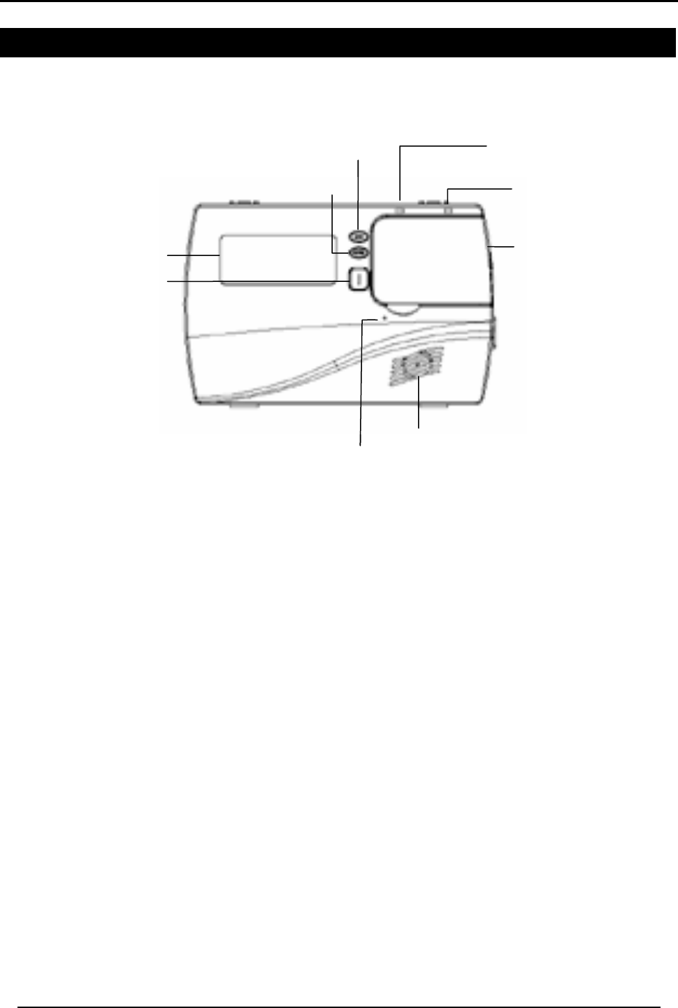
2.1 The Panel
Figure 1: HomeLogiXTM Panel
Menu Use to navigate between menus.
Power indicator Power LED: Red
Status indicator Status LED: green On: system armed.
Off: system disarmed.
Flash: entry and exit delay (according to beep rate)
Keypad door Open to access the keypad buttons
Local sounder System speaker
Microphone Enables the recording of voice messages
Local emergency button Keep pressed for 3 seconds to sound a standard panic alarm
Display LCD display
Enter Accept an entry or selection
Display
Status indicato
r
Keypad door
Local sounder
Local emergency
button
Microphone
Menu
Ente
r
Display
Power indicato
r
Status indicato
r
Keypad door
Local sounder
Local emergency
button
Microphone
Menu
Ente
r
HOMELOGIXTM QUICK REFERENCE
HomeLogiX Installer Manual
Page 7
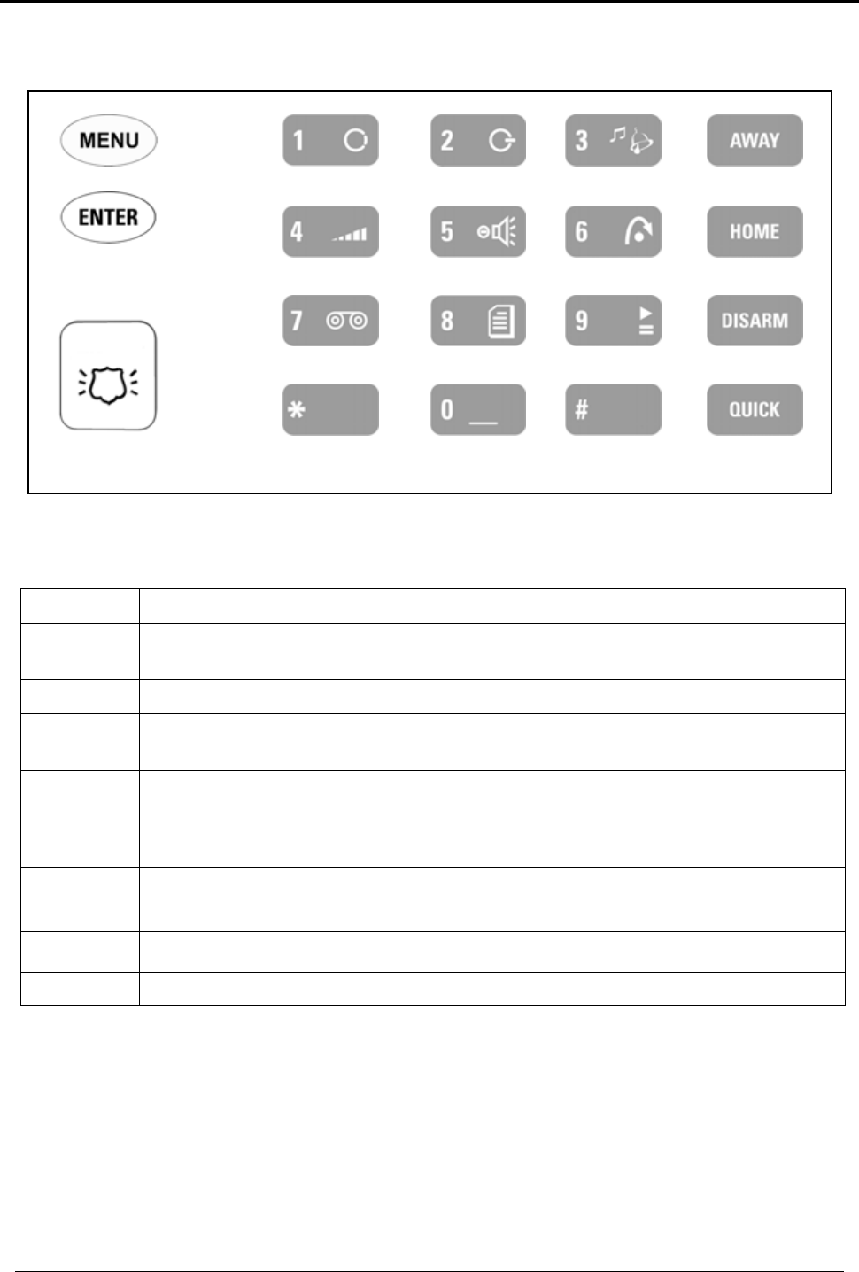
2.2 The Keypad
Figure 2: Keypad
The following table describes the keypad functions:
Key Press to
Menu Navigate between User and Installer menus, and Normal mode.
Navigate to the next menu or the next option within a menu.
Enter Accept an entry or selection.
Local
emergency When pressed for 3 seconds a standard panic alarm Sounds
Keys
0 - 9 Enter alphanumeric entries. Press 0 to enter a space.
Away Arms all sensors and detectors for use when there is no one at home/office
Home Arms all perimeter sensors and detectors as defined by the installer. For use
when home/office is occupied
Disarm Disarms all armed sensors and detectors
Quick (Esc) Ignore an entry or move one level up in a menu.
GHI
ABC DEF
JKL MNO
PQRS TUV WXYZ
MEM ESC

HOMELOGIXTM QUICK REFERENCE
HomeLogiX Installer Manual Page 8
2.2.1. Keypad Operated Functions
When the system is idle, the alphanumeric keys initiate the following commands:
Press To
0 Memory Display
Press once to display the alarms caused during the last arming period per
zone. The first line of the displays shows the alarm memory, and the second
line shows the zone description, event and time. The display toggles
between zone description and the date by pressing the Enter button.
Press Menu to display the next alarmed zone.
Press Esc to exit.
1 PGM ON
Press once to enter PGM activation mode, the PGM status is indicated on
the right. Press 1 to activate PGM 1 and/or 2 to activate PGM 2.
2 PGM OFF
Press once to enter PGM deactivation mode, the PGM status is indicated on
the right. Press 1 to deactivate PGM 1 and/or 2 to deactivate PGM 2.
3 Chime ON/OFF
Manually toggle the chime on and off.
4 Volume
Manually toggle the beep volume level.
5 Voice ON/OFF
Manually toggle voice messages on and off.
6 Bypass
Enter the User menu Bypass option.
7 Record User Message
Record a voice message of up to 15 seconds. Press and hold key 7
for 3
seconds to erase a message.
8 Event Log Display
Press once to display the event
log. The first line of the display shows the
event log and the second line shows the zone description (or system, if a
system event is displayed), event date and time. The display toggles
between zone description and the date by pressing the Enter button.
Press again or press Menu to display the next event.
Press Esc to exit the menu.
Note that a master code is required to access this function.
9 Play User Message
Listen to voice messages.

HOMELOGIXTM QUICK REFERENCE
HomeLogiX Installer Manual
Page 9
2.3 Sound Indicators
Following are the sounds emitted by the system and push buttons:
Sound Sounded when
Single beep A key is pressed
Long beep An attempt is made to enter an invalid or unacceptable entry
Two short beeps Button not pressed for a period of 30 seconds (except during test
mode). The system automatically exits the current menu.
Three short
beeps An entry is successfully accepted.
Nine short beeps Forced arming or zone bypass
Four short beeps
a minute If enabled, on trouble condition.
Short beep every
second An exit/entry delay is activated. (Beep sounded every 0.5 seconds
during last 10 seconds of delay.
Chime Activated
2.4 LED Indicators
This section describes the LED indicators of the power and status indicators
LED Behavior
Power
LED Red On when the system is ON.
Status
LED Green OFF when system is disarmed ON when system is armed. Flashing during
entry/exit delay, according to the beep rate specified

SPECIFICATIONS
HomeLogiX Installer Manual Page 10
3. SPECIFICATIONS
3.1 RF Data
RF Unit Type Integrated RF transceiver (two-way) shielded super heterodyne, fixed
frequency
Antenna Type Printed PCB type antenna
Operating
Frequencies 433.92 MHz G series
868.35 MHz H series
Receiver
Sensitivity Up to -68 dBm
Transmitter
Power Up to +10 dBm, less based on country requirements
Range
(open field) Up to 250 m in open space for detectors, and 110 m for hand-held
remote controls
RF Device ID
Coding three-bytes non-replicated per sensor type, or multiples of 16 million
possible codes, make it almost impossible to have two like coded
transmitters
The HomeLogiXTM system has optimum range if installed according to the
manufacturer’s recommendations, though this range may be affected by radio noise
from high-power nearby sources, or interference with the signal (blocking) by large
metal surfaces, or multiple concrete walls.
3.2 Environmental Data
• Operation temperature: 0º – 60º C (32º F - 140º F)
• Storage temperature: -25 º – 70º C (-13º F - 158º F)
• Relative humidity: 85% at 30º C Non condensing
• Dimensions: 220mm (L) x 140mm (W) x 48mm (D) (8.7"(L) x 5.5" (W) x 1.9" (D))
• Weight: 595gr. (1.3lbs.)
3.3 Electrical Data
• Display: 2 Lines of 16 characters, backlit LCD
• Two fully programmable PGM open collector outputs, 200mA, PTC protected
• External Siren output of 1A relay
• Case tamper protection
• On-board, supervised wired zone and wired tamper inputs
• Local, 87dbA siren
• External power supply: 220VAC / 50Hz, 110VAC / 60Hz (15VDC, 800mA)
• Current consumption: 250mA (standby), 500mA (max)
• Auxiliary power output: 12VDC, 500mA max
• Internal backup battery: 800mAh for 2 hours standby, 2 hours full alarm

SPECIFICATIONS
HomeLogiX Installer Manual
Page 11
3.4 Communication
• Frequencies: 433.92MHz (G version) and 868.35MHz (H version)
• RF Jamming detection (UL / EN selectable)
• Proprietary anti-collision RF protocol
• Programmable no-activity timer 1-30 minutes, per zone
• Two Central station numbers and accounts, backup and secondary modes
• Reporting protocols: Contact ID
• Three Private telephone numbers for voice reporting, and two way voice
communications
• Local connection (with MD-62) port for local upload/download, and remote
programming by PC software
• Built-in telephone dialer and 300 Baud modem

USER MENU STRUCTURE
HomeLogiX Installer Manual Page 12
4. USER MENU STRUCTURE
The user menu enables basic user settings such as setting the date and time, and
changing user codes. Up to twenty users can access most of the user menu settings,
each with their own code, including one master user who has access to all the
settings. Settings marked with an (M) can be accessed by the master user only, and
appear only if the master code was entered.
Note:
If the master code has not been specified, and the installer has set
the zone bypass to Off, the user menu is unavailable to regular users
To enter the user menu:
1. Press Menu until the screen displays User.
2. Press Enter.
3. Enter the master user code, the default code is 1234. The user menu options are
displayed, as follows:
Select To
(M) Edit Master
Code Change the master code
(M) User Codes Specify user codes 2 through 20. If the user code exists, you can edit
the code or delete the code.
(M) Set Date &
Time
Set the time, as specified in Date & Time Format. (Menu button specifies
the AM/PM format.)
Set the date, as specified in Date & Time Format.
(M) Date & Time
Format
Specify the format in which the date is specified: 24 hour format or
AM/PM.
Specify the format in which the date is specified: DD-MM-YY or MM-
DD-YY
Zone Bypass This option is enabled if manual bypass has not been set to Off by the
Installer. It enables you bypass/un-bypass a selected zone.
(M) Private
Numbers Specify up to three private telephone numbers.

INSTALLATION
HomeLogiX Installer Manual
Page 13
5. INSTALLATION
5.1 Unpacking the Equipment
The contents of your package are listed below. First, make sure that all the items in the
kit have been included. If you find that any item is missing, contact your dealer
immediately.
5.1.1. HomeLogiXTM Package Content
• HomeLogiXTM unit
• Transformer
• Telephone cable
• Backup battery
• Button pack (provided separately)
• Installation screw set
5.2 Supply Power to the Unit
It is easier to enroll the ID codes of the transmitting devices to the system before
installation. Power the HomeLogiXTM system using the external power transformer or
from the backup battery.
5.3 Planning & Programming
Register the location of each detector in the tables provided in Appendix A and B.
Mark the transmitters and detectors accordingly.
To Program the system, refer to PROGRAMMING on page 19.
To mount the HomeLogiXTM unit, refer to
Mounting the Back-plate on page 16.
5.4 Wiring the System
The HomeLogiXTM wiring plan is shown below.
Release each screw terminal block and connect accordingly.
6-lead RJ-11 cords are required for the telephone line or telephone line and telephone
set.
5.4.1. Wiring the HomeLogiXTM
AWAITING NEW DRAWING FROM ALEX
Figure 3: Panel Wiring
Input Description
Siren Relay output for external siren or strobe. Normally open or
normally closed for external siren contacts.
AUX 1
AUX 2 Programmable AUX outputs 1 and 2, 200 mA Sink Current 12VDC
INSTALLATION
HomeLogiX Installer Manual Page 14
open collector outputs Active Low.
GND Ground
ZONE Wired Zone (zone 40) Alarm input.
GND Ground
TAMPER Wired Zone (zone 40) Tamper input.
+15VDC VIN
GND Input voltage from AC/DC adaptor VIN=13.8-15 .
+13.8VDC (-) AUX
(OUT) Auxiliary Power output (to power external devices) +13.8 VDC
500mA Load current Max. Current limited.
LINE IN Telephone line in (from the wall to the system).
HOME TEL Telephone line out (from system to telephone device).
Connection
Socket Connection Socket for 10 pin plug connecting panel to PC with
MD-62.
+BAT- Battery
5.4.2. SIREN RELAY OUTPUT Wiring to External Siren
Relay output for external siren can be programmed as normally open or normally
closed (fail-safe) operation.
Figure 4: Siren
This output can be programmed by the installer to provide normally closed or normally
open dry contact output. This relay output will toggle the normal position in case of an
alarm and operates in the same method as the local siren.
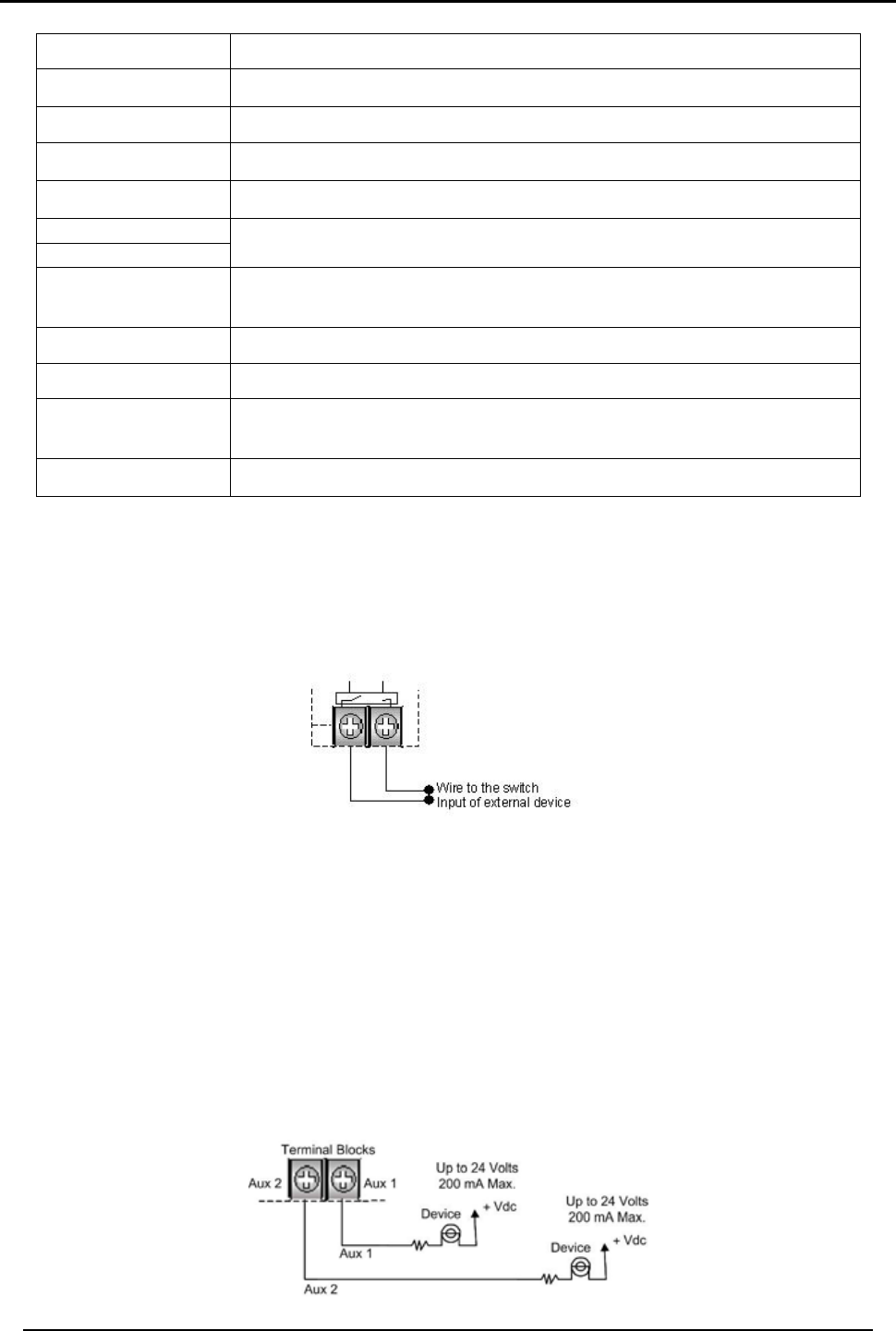
5.4.3. Wiring Auxiliary Outputs 1 and 2
Auxiliary outputs 1 and 2: This pair of outputs are open collectors with sink current
limited at 200 mA. The outputs work by connecting an external device to power
supply through an internal transistor in order to turn it on.
Figure 5: AUX
Inside HomeLogiXTM
INSTALLATION
HomeLogiX Installer Manual
Page 15
Both Aux 1 and Aux 2 have the same selection of programming.
When programming the Aux 1 and Aux 2 open collector outputs, it is possible to select
from several operational modes from the programming menu as described in the
programming section under Automation sub section Set Triggers on page 35.
5.4.4. Wiring the ZONE 1 Wired Input:
Wired input zone 40 for wired door detector.
Figure 6: Zone
This wired input acts as a regular sensor and functions likewise in armed and disarmed
mode.
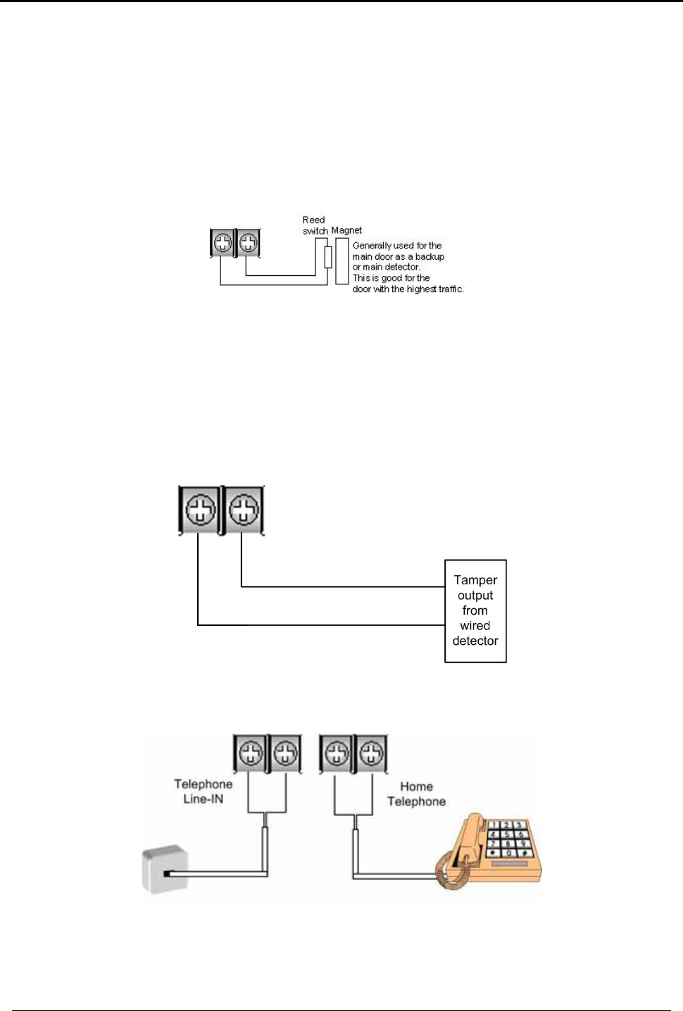
5.4.5. Wiring the Wired Tamper Input
Wired tamper input: 24-hour active on zone 40.
Figure 7: Tamper
5.4.6. Wiring the HomeLogiXTM Telephone connectors
Figure 8: Telephone
Terminal Blocks for Line-In and Tel Line-Out
Tamper GND
Tamper GND
INSTALLATION
HomeLogiX Installer Manual Page 16
5.5 Connect the AC Transformer
Note:
Complete all the wiring and programming before plugging the
transformer in the AC outlet
Attach the transformer and power up the system. The display shows the HomeLogiXTM
logo and the current version.
Plug in the transformer – the power LED on the control panel should light up.
5.6 Connecting to a Computer
The control panel can be equipped with an optional MD-62 adaptor for serial data
interchange with a computer.
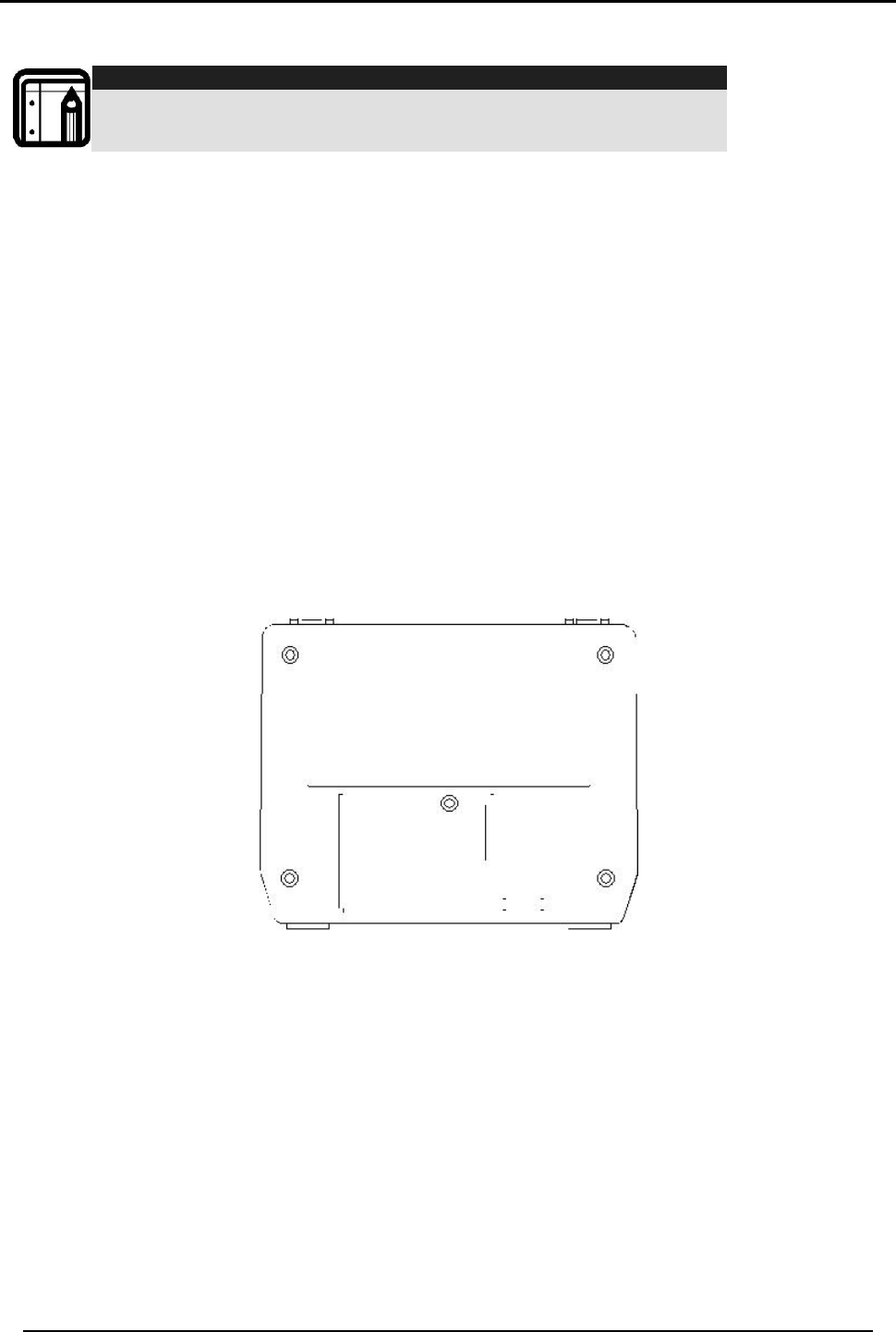
5.7 Mounting the Back-plate
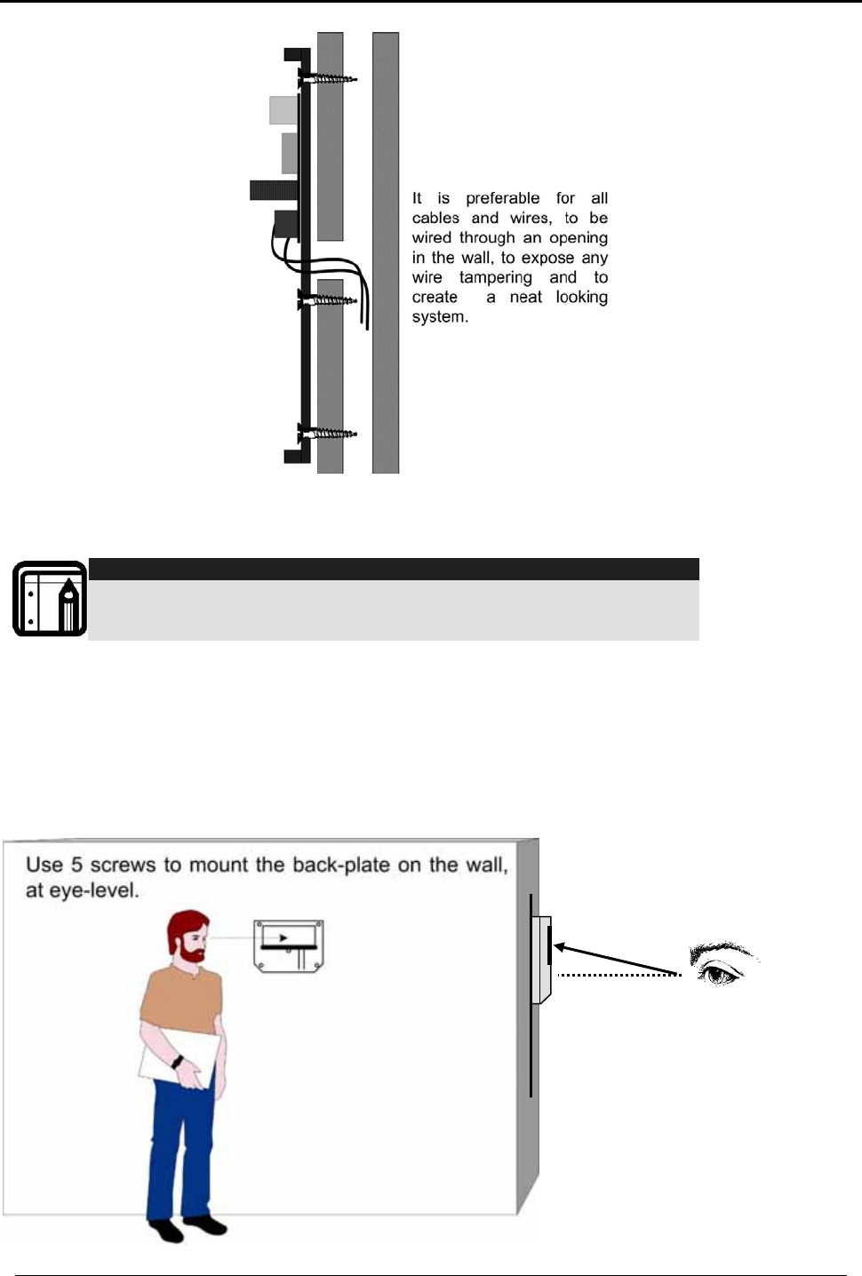
5.7.1. General
There are two options on how to prepare the mounting location; in order to complete
the installation without exposed wires, all the wiring should be done through the wall.
The wiring to the back-plate can be done without having exposed wires, by installing
the panel on a standard electrical box, or making a hole in the wall for the wiring.
INSTALLATION
HomeLogiX Installer Manual
Page 17
Figure 9: Back Plate
When drilling the hole for the wires, it is recommended to drill the hole in the marked
out area.
Note:
It is important to mount the back-plate first before connecting any
of the wiring to the unit
5.7.2. Required Space
The required space on the wall for the panel is (L) x (H). Hole size for wires: 2cm x 5cm.
This is to be drilled according to the openings on the back-plate.
The optimum viewing angle of the LCD is achieved when the panel is mounted above
the eyelevel of the user.
Figure 10: Mounting
Eye level
Place panel above eye
level for best viewing
angle
INSTALLATION
HomeLogiX Installer Manual Page 18
5.8 Dismounting the Control Panel
Release HomeLogiXTM from the mounted back-plate by unlocking the locking hooks
on the top of the back-plate by lifting them up and out of the recesses on top of the
panel.
Pull the top of the panel away from the wall to disconnect the connector to the back
plate, and then remove the panel from the lower posts of the back-plate.
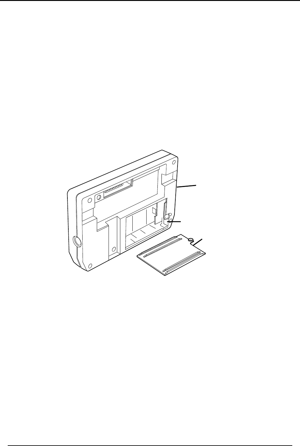
5.9 Replacing the Backup Battery
To replace the backup battery:
• Dismount the panel.
• Remove the battery cover
• Replace the battery
• Replace the cover
Figure 11: Backup Battery
Panel
Removable
Batter
y
Doo
r
+
-Battery
Connections
+
-

PROGRAMMING HOMELOGIXTM
HomeLogiX Installer Manual
Page 19
6. PROGRAMMING HOMELOGIXTM
6.1 Overview
We recommend that you program HomeLogiXTM before installing it. You can use the
backup battery or the AC power supply for operating power while programming.
Access the HomeLogiXTM installer’s menu by entering the default 4-digit installer’s
code: 8888.
HomeLogiXTM is provided with two default codes:
Default installer code: 8888 – which enables you to program HomeLogiXTM
Default Master code: 1234 – which enables you to change the master code and
modify the User and Master options
We recommend that you change the master and installer codes after first time use.
6.2 Enrolling Wireless Devices and Remote Controls
You can enroll detectors, remote controls, keypads, sirens and repeaters.
Note:
Enrolling is not available for Wired Zone #40. It can only be enabled
or disabled (Default: disabled). Zone 40 uses the wired zone and
tamper inputs
Before enrolling wireless devices and remote controls, make sure they all contain the
appropriate batteries.
INSTALLERS MENU
HomeLogiX Installer Manual Page 20
7. INSTALLERS MENU
The Installer’s menu enables access to the following group of options:
• Change code
• Zones
• Enrolling
• Security
• Communications
• Automation
• Messages
• Maintenance
7.1 Accessing the Installer Menu
Press the Menu button twice to reach the INSTALLER MENU option and press Enter.
Note:
The default password for entering the Installer menu is “8888”.
If a wrong code was entered, the system will emit a long beep indicating an error and
waits once again for the correct code to be entered, after 30 seconds the system to
return to normal mode.
No activity for 4 minutes will cause the system to return to normal mode, to return to
the normal mode before the 4 minutes are up press the Quick button.
Once in the INSTALLER MENU use the Menu button to browse the sub menus. Press
Enter to access the desired sub menu as detailed below.
7.2 Change Code
CHANGE
CODE Zones Enrolling Security
Communications
Automation
Messages
Maintenance
This option enables you to change the code with which you enter the system. The
default code is 8888.
To change the installer code:
The first sub menu is CHANGE CODE. Press the Enter button to access the sub menu,
type a new four-digit installer code and press Enter to save your new code.

INSTALLERS MENU
HomeLogiX Installer Manual
Page 21
7.3 Zones
Change
Code ZONES Enrolling Security Communications
Automation
Messages Maintenance
Zone #01-40
Zone Type
Description
Chime
No activity
This menu allows you to define each of the 40 available zones. You can define the
zone type, description, activity type and it’s audible chime indication.
To specify zones:
The second sub menu is ZONES. Select the required zone by either browsing all 40
using the Menu button or by entering the zone number using the numeric keypad.
Once in the desired zone, use the Menu button to browse the options, press Enter to
access the desired sub menu in order to define several characteristics as follows:
• Zone Type; select one of the following:
o Interior
o Perimeter
o Delay
o Fire
o 24 Hour Silent
o 24 Hour Audible
o Chime
Description; select one of 39 fixed descriptions or one of five editable custom
descriptions. HomeLogiXTM enables you to specify five custom zones, see Using the
Menu button, Enable or Disable the option and press Enter to confirm your selection.
• Custom menu on page 36, use the tables in SENSOR PLACEMENT and HELPFUL
REFERENCE TABLES on page 45
• Chime; select one of three chimes, or no chime. By default zone is “no chime”
• No Activity Time; select Enabled or Disabled, By default the option is disabled
INSTALLERS MENU
HomeLogiX Installer Manual Page 22
7.4 Enrolling
Change
Code Zones ENROLLING Security Communications
Automation
Messages Maintenance
Detectors
Remote
controls
R. Sirens
Keypads
Repeaters
The Third sub menu is ENROLLING. Browse the desired application listed below using
the Menu button and access it by pressing the Enter button:
• Detectors
• Remote controls
• Sirens
• Keypads
• Repeaters
7.4.1. Detectors
You can enroll up to 39 detectors, one detector per zone, numbered 01 through 39.
Zone no. 40, which is dedicated to a hardwire detector can only be enabled or
disabled under this sub-menu, by default this zone is disabled.
To enroll/delete a detector:
Select the desired zone by either browsing all 39 zones using the Menu button or by
entering the zone number using the numeric keypad.
If no detector is associated to the selected zone, for 30 seconds the screen will show a
message saying “waiting for detector signal” initiate a transmission from the detector
(Alarm, Tamper, or any other transmission available, see the detector’s manual for
reference). When the transmission is detected you will be asked to press the Enter
button to store the detector into the zone.
Note:
When enrolling smoke and heat detectors, select the zone type “fire”.
If no signal is received with the allocated 30 seconds the unit will return to normal
mode.
If the selected zone has a detector associated, you will be asked whether you wish to
delete it. Press Enter to delete the detector or the Quick (ESC) button to go back.

INSTALLERS MENU
HomeLogiX Installer Manual
Page 23
7.4.2. Remote Controls
You can enroll up to eight remote controls, and specify functions for each button on
the remote control. You can also delete enrolled remote controls.
To enroll a remote control and specify a function:
Select the desired remote control number 01-08 by either browsing the remotes using
the Menu button or by entering the remote number using the numeric keypad.
Enroll the remote control when the WAITING FOR SIGNAL message is displayed, by
pressing a button on the remote you wish to enroll, When the signal is detected you
will be asked to press the Enter button to store and save your selection. Once the
selection is stored, you can then choose to configure each of the remote control
buttons to behave in one of the following options:
• Restore Default (will set the button to it’s original functionality)
• Operate PGM 1
• Operate PGM 2
• Status Request
At any time press the Quick (ESC) button to exit the menu, Once you exited the menu
(after saving the enrollment) you cannot change the button’s behavior, unless you
delete the remote and re-enroll it.
To delete a remote control
Select the pre-enrolled remote control number 01-08 by either browsing the remotes
using the Menu button or by entering the remote number using the numeric keypad.
You will be asked whether you wish to delete it. Press Enter to delete the detector or
the Quick (ESC) button to go back.
7.4.3. RF Siren
You can enroll up to four RF Sirens. You can choose to remove enrolled sirens.
To enroll/remove an RF Siren:
• Select the required Siren location, #01-04 by either browsing the keys using the
Menu button or by entering the siren’s number using the numeric keypad
• Enroll the RF Siren when the WAITING FOR SIGNAL option is displayed, by
activating the siren’s tamper, When the signal is detected you will be asked to
press the Enter button to store and save your selection
• If the selected location has a siren enrolled, you will be asked whether you wish
to delete it. Press the Enter button to delete or the Quick (ESC) button to go
back

INSTALLERS MENU
HomeLogiX Installer Manual Page 24
7.4.4. Keypads
You can enroll up to four keypads. You can choose to remove enrolled keypads.
To enroll/remove a keypad:
• Select the required keypad location, #01-04 by either browsing the keys using
the Menu button or by entering the keypad’s number using the numeric keypad
• Enroll the keypad when the WAITING FOR SIGNAL option is displayed, When a
signal is detected you will be asked to press the Enter button to store and save
your selection
• If the selected location has a keypad enrolled, you will be asked whether you
wish to delete it. Press the Enter button to delete or the Quick (ESC) button to go
back
7.4.5. Repeaters
You can enroll up to four repeaters. You can choose to remove enrolled repeaters.
To enroll/remove a repeater:
• Select the required repeater location, #01-04 by either browsing the keys using
the Menu button or by entering the repeater’s number using the numeric
keypad
• Enroll the repeater when the WAIT FOR SIGNAL option is displayed, by activating
the tamper, When the signal is detected you will be asked to press the Enter
button to store and save your selection
• If the selected location has a repeater enrolled, you will be asked whether you
wish to delete it. Press the Enter button to delete or the Quick (ESC) button to go
back
7.5 Security
The following is a list of the various security features of the system.
Change
Code Zones Enrolling SECURITY Communications
Automation
Messages Maintenance

INSTALLERS MENU
HomeLogiX Installer Manual
Page 25
Exit Delay
Entry Delay
Auto Arming
Siren Time
Siren Mode
Relay Polarity
Local Siren
Supervision Time
Jamming
No Activity Time
Trouble Beeps
Bypass Option
Quick Arm
Panic Button
Duress Code
Alarm Cancel
Alarm Abort Time
Backlight Time
Hide Display
Key Beeps
The fourth sub menu is SECURITY. Browse the desired security related setting, as
described in detail ahead, using the Menu button, press the Enter button to access it.
7.5.1. Exit Delay
An exit delay enables the user to arm the system, and exit the site through a specified
door, after arming the system, without setting off an alarm.
Slow-rate warning beeps sound when the system is armed, the beeping rate increases
during the last ten seconds of the delay. The exit delay is set at 30 seconds by default.
To specify the exit delay:
Using the numeric keypad, specify the length of time for the exit delay between 1 and
99 seconds and press Enter to save your selection.
7.5.2. Entry Delay
An entry delay enables the user to enter the site through a specified door without
setting off an alarm. The entry delay is set at 30 seconds by default.
After entry, the user must disarm the system before the entry delay expires. Slow-rate
warning beeps sound upon detection of the specified zone/s, the beeping rate
increases during the last ten seconds of the delay.

INSTALLERS MENU
HomeLogiX Installer Manual Page 26
To modify the entry delay:
Using the numeric keypad, specify the length of the entry delay between 1 and 99
seconds and press Enter to save your selection.
7.5.3. Auto Arming
Auto Arming allows scheduled arming and disarming of the system for all weekdays at
different hours.
To activate auto arm:
Using the Menu button, select the day of the week and press Enter to confirm.
Using the Menu button, select one of the following options and press Enter to confirm:
• Disabled
• Arm Home
• Arm Away
Enter a time (24 hour time convention) to arm the system using the numeric keys and
press Enter to confirm the time, repeat the process for the disarm time.
7.5.4. Siren Time
Specifies the amount of time the siren will sound when an alarm has been set off. The
siren time is set to three minutes by default. This relates to all siren types, wired, wireless
and local.
To specify the siren time:
Using the numeric keypad, specify the length of the siren time between 00 and 99
minutes (00 disables the siren) and press Enter to save your selection.
7.5.5. Siren Mode
You can specify whether you want the siren to be activated on Away only or both
away and home alarms, the siren mode is set at Away + Home by default. This relates
to all siren types, wired, wireless and local.
To specify the siren mode:
Using the Menu button, select one of the following options and press Enter to confirm:
• Away
• Away + Home
7.5.6. Relay Polarity
Depending on the input trigger of the hardwired siren you are using specify the relay
polarity to either Normally Open or Normally Closed. The siren relay polarity is set to
N.O. (normally open) by default.

INSTALLERS MENU
HomeLogiX Installer Manual
Page 27
To set the relay polarity:
Using the Menu button, select one of the two options, N.O. or N.C., and press Enter to
confirm.
7.5.7. Local Siren
Specifies whether an activated alarm causes an internal siren (emitted from the
system’s speaker) to sound or remain silent. The local siren is enabled by default.
To set up a local siren:
Using the Menu button, select one of the two options, Enable or Disable, and press
Enter to confirm.
7.5.8. Supervision Time
Specifies the time limit during which the system receives supervision reports from
specified wireless devices. If a device does not report-in at least once within the
specified time limit, the system initiates an inactivity alert. Default is set to one hour.
To specify the supervision time:
Using the Menu button, select on of the time limit options, 1, 2, 4, 6, 8, 16, 24 or 48
hours, during which the system receives reports and press Enter to confirm.
7.5.9. Jamming
Specifies whether the system detects and reports jamming – interferences on the radio
channel used by the system. The jamming detection is disabled by default.
To specify jamming detection:
Using the Menu button, select one of the following options and press Enter to confirm:
• Disabled: to disable jamming detection
• EN enabled: to enable European standard jamming detection
• UL enabled: to enable US standard jamming detection
7.5.10. No Activity Time
Specifies the time limit in which the system should receive a signal from a sensor used
to monitor the activity of sick, elderly or disabled people. If no device detects and
reports movement at least once within the specified time limit, a “not active alert”
sounds. This option is disabled by default.
To set the no activity time:
Using the Menu button, select one of the following options and press Enter to confirm:
• 1, 2, 5, 10, 15, or 30 minutes
• Disable the timer

INSTALLERS MENU
HomeLogiX Installer Manual Page 28
Note:
Required zones should be set to ‘Enabled’ for this security feature to work
7.5.11. Trouble Beeps
Determine whether the system will emit a “trouble beep” indicated by a series of four
short beeps once a minute for the following “Trouble” events:
• Low battery (detectors and system)
• Supervision loss (detectors)
• Power failure (system)
• Communication failure (system)
• Tamper(system and zones)
• RF jamming
The default is set to Enabled
To specify trouble beeps:
• Using the Menu button, choose to Enable or Disable the trouble beeps and
press Enter to confirm
7.5.12. Bypass
Specifies either manual bypassing of individual zones, or enables the system to
forcedly arm open zones when armed. Bypass is turned off by default.
To set bypass:
Using the Menu button, select one of the following options and press Enter to confirm:
• Off to set the bypass off
• Off Force/Manual to set the manual bypass
• Manual/Force to set the forced arming (automatic bypass)
7.5.13. Quick Arm
Enables the user to arm the system without entering a code; Quick Arm is set to
disable by default.
To enable/disable quick arm without a code:
Using the Menu button, select one of the following options and press Enter to confirm:
• Enter Installer menu/Security/Quick Arm/Enable
• Enter Installer menu/Security/Quick Arm/Disable
To utilize quick arm:
• Give a long press on the ESC key.
The panel is armed AWAY or HOME.

INSTALLERS MENU
HomeLogiX Installer Manual
Page 29
7.5.14. Panic Button
Enables the user to generate an alarm (audible or silent) by pressing the emergency
button on the control panel, the remote control panic button will remain active at all
times if enrolled. The local emergency button is disabled by default.
To set a panic button:
Using the Menu button, select one of the following options and press Enter to confirm:
• Audible: to set an audible panic alarm that transmits a message to the CMS or
private telephone set.
• Silent: to set a silent panic alarm that transmits a message to the CMS or private
telephone set, but without a siren
• Disabled: to disable the panic alarm button all together
7.5.15. Duress Code
The system allows you to define a duress code, which a user can enter when forced to
disarm the system under duress. By default, the duress code option is disabled, and
there is no duress code set.
Note:
The duress code should NOT be identical to any other existing code.
To change the duress code:
Type a new four-digit duress code using the numeric keypad and press Enter to save
your new code.
To disable the duress code:
Press the pound key (#), the code will disappear, and the duress code option will be
disabled, press Enter to save.
7.5.16. Alarm Cancel
Specifies the amount of time during which if the user disarms the alarm, the system
sends a “Cancel Alarm” message to the central station. By default, The Alarm Cancel
is set to 00 minutes (disabled).
To set the Alarm Cancel:
Using the numeric keypad, set the alarm cancel time between 01 – 60 minutes, or set it
to 00 to disable the option.
7.5.17. Alarm Abort Time
The system will sound a warning, but the central station will not receive notification of
the alarm if the user disarms the system within the specified alarm abort time. This
function applies to interior and/or perimeter zones only. The Alarm Abort Time is set to
00 minutes (disabled).

INSTALLERS MENU
HomeLogiX Installer Manual Page 30
To set the alarm abort time:
Using the numeric keypad, set the alarm abort time between 01 – 60 seconds, or set it
to 00 to disable the option.
7.5.18. Backlight Time
Specifies the backlight options; by default, the backlight time is set at 15 seconds.
To set the backlight:
Using the Menu button, select one of the following options and press Enter to confirm:
• Always: to specify that the keypad and buttons are backlit at all times.
• 15 secs: to specify that the keypad and buttons are backlit for up to 15 seconds
after last key press.
7.5.19. Hide Display
Enables you to specify that when armed, the system will not display the system
statuses or other system prompts; by default, Hide Display is off.
To display the system status:
Using the Menu button, select one of the following options and press Enter to confirm:
• Off to display status and prompts.
• On to hide status and prompts.
7.5.20. Key Beeps
Choose to turn Key beeps on to hear a beep on each key press; by default, the Key
beeps is off.
To set the key beeps:
Using the Menu button, select one of the following options and press Enter to confirm:
• On to turn the key beeps on
• Off to turn the key beeps off
INSTALLERS MENU
HomeLogiX Installer Manual
Page 31
7.6 Communications
Change
Code Zones Enrolling Security COMMUNICATIONS
Automation
Messages Maintenance
System Telephone
Private Report
CS Report Setup
Line Test
AC Fail Report
2WV SETUP
Fax Defeat
Number of Rings
The fifth sub menu is Communication, which deals with the setup of system
communications parameters and settings with the outside world. Browse the desired
communication related setting, as described in detail ahead, using the Menu button,
press the Enter button to access it.
7.6.1. System Telephone
This menu allows you to specify the telephone number used for the ring back option
when calling the system telephone.
To set up the system telephone:
Using the numeric keypad, enter the system telephone number and press Enter to
confirm. Press the pound key (#) to delete an existing number.
Note:
When setting up the system telephone, use a comma (,) to indicate a delay
when dialing a number.
7.6.2. Private Report
This menu enables you to set the private telephone report options as detailed below.
To set up private report:
Using the Menu button, select from the following options and press Enter to confirm:
Set Numbers, specifies the telephone numbers of the subscribers to which the system
reports. You can enter up to three numbers. Using the Menu button, choose between
number 1, 2 or 3 and press Enter. Using the numeric keypad, enter the telephone
number and press Enter to confirm. Press the pound key (#) to delete an existing
number.
Note:
When setting up the system telephone, use a comma (,) to indicate a delay
when dialing a number.

INSTALLERS MENU
HomeLogiX Installer Manual Page 32
• Report Options specifies the event groups that are included in a report. Using
the Menu button, Enable or Disable a group, as required and press Enter to
confirm:
o Alarms (enabled by default)
o Troubles (enabled by default)
o Alerts
o Bypass
o Arm/disarm
o Restore
• Dialing Attempts specifies the number of times the system attempts to dial a
private number before dialing the next specified private number. Using the
Menu button, specify between 1, 2, 3, 4, or 5 dialing attempts press Enter to
save. The default is 3 attempts.
7.6.3. CS Report Setup
This menu enables you to set up the Central Station (CS) report options:
To set up CS report:
Follow these steps:
• CS Report method specifies the reporting method. Using the Menu button,
select one of the following and press Enter to confirm:
o Primary Only(default)
o Alternate
o Secondary
o Both
o Disable
• CS Primary specifies the first telephone number of the first central station to
which the system reports in case of an event, and the primary account code –
the number that identifies your system to the central station. The events
reported are the events specified during setup.
Follow these steps:
Note:
For PABX use the digit followed by "*" and then the full number
o Phone Number, Using the numeric keypad, enter the CS telephone
number, press Enter to save, Press the pound key (#) to delete an existing
number
o Account Code, Using the numeric keypad, enter a code of four digits
and press Enter to confirm
o Report Options specifies the event groups which are included in a report.
Using the Menu button, Enable or Disable a group, as required and press
Enter to confirm:
Alarms (enabled by default)

INSTALLERS MENU
HomeLogiX Installer Manual
Page 33
Troubles (enabled by default)
Alerts
Bypass
Arm/disarm
Restore
• CS Secondary specifies the secondary telephone number dialed and the
secondary account code – the number that identifies your system to the
second central station. The events reported are the events specified during
setup. Follow the instructions in CS Primary
• Protocol, specifies the reporting protocol used by the system to report events to
the central stations. Currently only Contact ID is available.
• Dialing Attempts specifies the number of times the system attempt to dial the
primary stations number before attempting to dial the secondary number. Using
the numeric keypad select 1 to 16 attempts, press Enter to save. The system is
set to 3 attempts by default.
7.6.4. Line Test
Enables you to specify the time when the telephone line and CS reporting is tested
and reported to the central station, as well as the number of days between each test
(CS periodical reporting).
To set up line test:
Using the Menu button, select between the two options, and press Enter to confirm:
• Repeats, specifies the number of days between tests. Using the numeric
keypad, choose 1 to 30 days press Enter to save; default is 7.
• Test Time Using the numeric keypad, specifies the time of day (24-hour day
convention) to perform the test by typing the four digits of the desired hour,
press Enter to save. The test time is set at 12:00 by default.
7.6.5. AC Fail Report
This option allows you to specify a delay time, before reporting the power failure to the
CS, in which time power may be restored. The time is set to 0 (disabled) by default.
To set up AC fail report:
Using the numeric keypad, set the time between 1 – 240 minutes, or set it to 0 to
disable the option, press Enter to save.
7.6.6. 2-Way Voice Behavior
The HomeLogix panel enables the CMS operator to open a 2-Way Voice session with
the panel. The only events used in 2-way voice are: TAMPER, EMERGENCY, and
ALARM/RESTORE.
In general, 2-Way Voice Behavior option is achieved via simplex telephone
communication. The CMS operator can listen, talk, or close communication by

INSTALLERS MENU
HomeLogiX Installer Manual Page 34
selecting #1 (Listen), #3 (Talk), or #9 (Close communication) in the event the system
calls when an alarm is sounded. The installer can set the following options:
• CMS 2-way voice Enable/Disable
• CMS 2-way voice Timeout
However, if the KEY ON, TROUBLE, BYPASS, and MISC events are reported, and the
CMS is in LISTEN-IN mode, the CMS receptionist can hear the alarm/emergency voice
message events, if they belong to the same CMS.
On the other hand, if those events belong to another CMS, they will be reported after
the current CMS session report has finished.
To set up 2 way Voice Behavior:
1. In the 2WV SETUP menu, select CS 2WV ENABLE.
2. Select ENABLE.
3. Select CS 2WV TIMEOUT.
4. Enter a timeout value that does not exceed 180 seconds.
Note:
It is recommended to use 180 seconds for Timeout.
5. Press Exit to return to Normal mode.
7.6.7. Fax Defeat
When calling the system, fax and answering machines may need to be overridden.
This menu specifies whether to enable or disable this override. By default, this option is
disabled.
To set up Fax Defeat:
Using the Menu button, Enable or Disable the option and press Enter to confirm.
7.6.8. Number of Rings
Specify the number of rings before the system answers the line. By default, this option is
set to 4 rings.
To specify the number of rings:
Using the numeric keypad, set the number of rings to between 1 and 15, and press
Enter to confirm.
7.6.9. Select Region
Select the region in which the time is set for the system. By default, this option is set to 4
rings. By default, this option is Other.
To select the region:
Select the region from the drop down menu (or leave the default of Other), and press
Enter to confirm.

INSTALLERS MENU
HomeLogiX Installer Manual
Page 35
7.7 Automation
Change
Code Zones Enrolling Security Communications
AUTOMATION
Messages Maintenance
Keypad Manual
Set Triggers
The sixth sub menu is Automation, which deals with the setup of various home
automation options. Browse the desired automation related setting, as described in
detail ahead, using the Menu button, press the Enter button to access it.
7.7.1. Keypad Manual
Enable or disable this option to determine whether the PGM output can be controlled
by numeric keys 1 and 2 of the keypad as described in the Keypad Operated
Functions section above, this option is enabled by default.
To set up the keypad:
Using the Menu button, Enable or Disable the option and press Enter to confirm your
selection.
7.7.2. Set Triggers
Enables you to activate the PGM’s, using various events in an automated fashion. By
default, no triggers are set.
To set up triggers:
Using the Menu button, select PGM1 or PGM2, and press Enter to confirm.
For each of the PGM’s you can select the pulse time and triggers as described below:
• Pulse time - set the length of time for the device to stay on when a pulse type
activation is selected. Using the numeric keypad, set the time from 1 to 99
seconds and press Enter to save.
• Select the trigger type and parameters according to the following options:
Trigger PGM Activation Options Remarks
Arm Away On, Off, Pulse, Ignore
Arm Home On, Off, Pulse, Ignore
Disarm On, Off, Pulse, Ignore
Alarm Enabled, Disabled Go OFF when alarm stops
Panic Pulse, Ignore
Trouble Pulse, Ignore
AC Loss Enabled, Disabled ON when AC fails, OFF when AC returns
Remote Control On, Off, Pulse, Trouble, Ignore Relates to remote’s panic button
Zone On, Off, Pulse, Trouble, Ignore Relates to zone open or detection

INSTALLERS MENU
HomeLogiX Installer Manual Page 36
7.8 Messages
Change
Code Zones Enrolling
Security Communications
Automation
MESSAGES Maintenance
Keypad Mute
House Name
Custom Zones
The seventh sub menu is Messages, which deals with custom text and voice zone
descriptions, Personal messages between users and message mute options. Browse
the desired setting, as described in detail ahead, using the Menu button, press the
Enter button to access it.
7.8.1. Keypad Mute
This option allows you to enable or disable the option to mute all the voice messages
and beeps (except for trouble beeps) by numeric key 5 of the keypad as described in
the Keypad Operated Functions section above. By default, this option is Disabled.
To set up keypad mute:
Using the Menu button, Enable or Disable the option and press Enter to confirm your
selection.
7.8.2. House Name
Enables you to record and listen to the House Name of the system.
To record a House Name message:
1. In the Installer Menu, select Messages.
2. Page till you get to House Name menu.
3. In the House Name menu, select ENTER TO RECORD.
4. Press Enter to start and stop recording.
5. Press ENTER TO LISTEN after a recording has been entered.
7.8.3. Custom Zones
Enables you to record and listen to five voice and text custom zones descriptions and
to toggle between them. On each zone, the user can simply edit the text by typing
the keypad buttons, the text is limited to 16 characters.
To record a Custom Zone message:
1. In the Custom Zone menu, select a Custom Zone.
2. Press ENTER TO RECORD.
3. Press Enter to record the next zone.
4. Repeat 5 times.
INSTALLERS MENU
HomeLogiX Installer Manual
Page 37
5. Press ENTER TO LISTEN. This appears after the string of recordings have been
entered.
6. Press Enter to stop the listening to one zone and move to the next zone. This
option is circular.
Note:
Reset to factory settings does not delete these recordings.
7.9 Maintenance
Change
Code Zones Enrolling
Security Communications
Automation
Messages MAINTENANCE
Factory Default
RF Test
Test Indicators
Test Sirens
Test Devices
The eighth sub menu is Maintenance, which describes the various system
maintenance options. Browse the desired security related setting, as described in
detail ahead, using the Menu button, press the Enter button to access it.
7.9.1. Factory Defaults
This option allows you to restore the default factory settings for the system.
To restore factory default:
Press the Enter button to confirm.
7.9.2. RF Test
RF testing checks the signal strength of all the wireless devices enrolled to the system. If
a weak signal is detected, a repeater may be used to improve the link quality.
The system saves the most recent set of RF test results for uploading. The system clears
the tests when running another RF test.
To perform the test:
Using the Menu button select the test you wish to perform, press the Enter button to
access the test. Activate the RF unit to send a signal to the unit. The results can be
Strong, Normal or Low. The available tests are:
• Test Detectors
• Test R. Controls
• Test R. Siren
• Test Keypads

INSTALLERS MENU
HomeLogiX Installer Manual Page 38
• Test Repeaters
To view the results:
For each of the tests, you can review the results by pressing the Enter button and then
either the Menu button or the alphanumeric keys review all the units.
To exit the RF test mode you must press the Quick (ESC) button
7.9.3. Test Indicators
The indicators test checks the two indicator LED’s, power and status located on the
Panel.
To test the indicators:
After entering this menu press Enter the LEDs will blink three times
7.9.4. Sirens test
This test checks the different available sirens by activating them.
To test the sirens:
1. Select the siren you wish to test:
• Local Siren
• External siren
• RF siren
o Siren 1
o Siren 2
o Siren 3
o Siren 4
2. Press Enter to activate the sounder.
3. Press ESC to stop the siren.
7.9.5. Test Devices
This test checks the PGM’s connected to the system.
To test the PGM devices:
1. Select the PGM you wish to test:
• PGM 1
• PGM 2
2. Press Enter to activate the PGM for three seconds.

READING THE EVENT LOG
HomeLogiX Installer Manual
Page 39
8. READING THE EVENT LOG
The HomeLogiXTM event log stores up to 128 events. When the log is full, the new
incoming event replaces the oldest event.
Events are displayed in a chronological order, and include the date and time of their
occurrence.
To Access the Event Log:
Access the event log by pressing 8 on the keypad when the system is in normal mode.
To read an event, enter the master code and press Enter.
Browse the even log using the Menu button, press Enter to view the date and time of
the occurrence.
Note:
When accessing the Event Log via the PC software the words “Remote
Control 8” are displayed.
ACCESSORIES
HomeLogiX Installer Manual Page 40
Annex I. ACCESSORIES
I.1 HomeLogiXTM Compatible Detectors
A wide assortment of wireless detectors is compatible with the HomeLogiXTM control
panel, primarily for use in intrusion and personal safety applications. There are also
other system components, such as RF repeaters for extending range, and wireless
sirens for remote annunciation of alarms. To cover all the possible solutions of
integration, a Universal RF Transmitter is available, which can interface with almost any
type of wired sensor and enable it to communicate to the HomeLogiXTM by radio link.
Note:
For the model numbers shown below, XX denotes a variation on frequency and
country of application. Each detector comes with its own installation manual. All
the wireless detectors are powered by high-capacity lithium primary cells, which
provide long battery life.
The control panel identifies the detectors by means of a unique three-byte
identification code (ID Code), which offers up to 16 million possible combinations. The
ID is transmitted with every radio message. In addition to the ID, each detector
provides local intelligence of events such as the following, by radio link to the panel:
• Tamper open and restore events;
• Alarm events;
• Low battery and restore events.
Each detector also generates a supervisory full status transmission every 20 minutes.
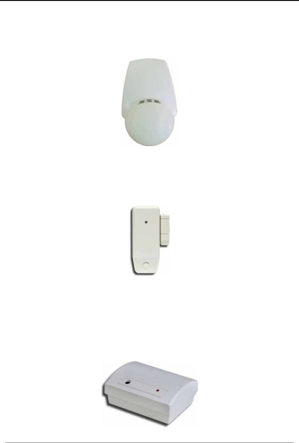
I.1.1. Wireless Passive Infra-Red (Motion) Detector
This sensor (Figure 1) is used to secure volumetric indoor areas. It employs a precision-
optics patented Fresnel lens, an ultra-sensitive infrared silicon sensor, and advanced
microcontroller digital signal analysis. The sensor is housed in tamper-detection
housing. The sensor can be mounted to any rigid flat or corner surface to cover the
desired volumetric space to be protected; a corner mount is available to enable
corner tamper detection. When motion is detected, the PIR transmits a message to
the control panel. If the control panel is armed, then the system will generate an
alarm.
Figure 12 SA-01 Wireless PIR Motion Detector
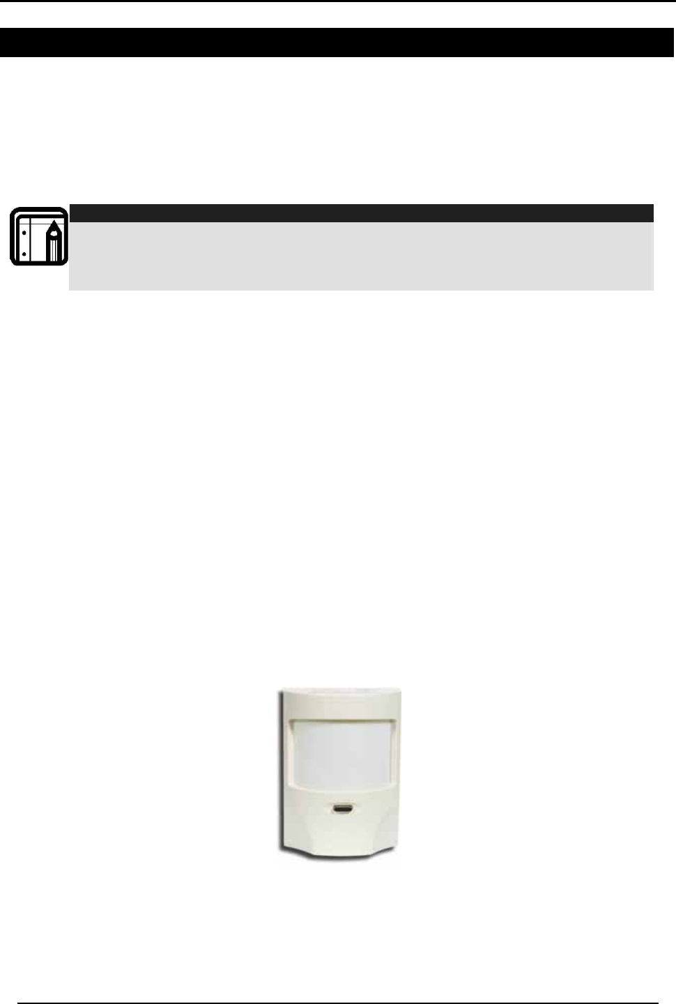
I.1.2. Advanced Wireless Spherical PIR (Motion) Detector
This sensor (Figure 2) is used to secure volumetric indoor areas. It employs a unique
Spherical Fresnel lens with creep-zone and an optional snap-in curtain mask, an ultra-
sensitive infrared silicon sensor, and advanced microcontroller digital signal analysis.
ACCESSORIES
HomeLogiX Installer Manual
Page 41
The sensor is housed in a dual tamper-detection, modernly designed housing. The
sensor can be mounted to any rigid flat or corner surface to cover the desired
volumetric space to be protected; a corner mount is available to enable corner
tamper detection. When motion is detected, the PIR transmits a message to the
control panel. If the control panel is armed, then the system will generate an alarm.
Figure 13 PYR-2011 Wireless PIR Motion Detector
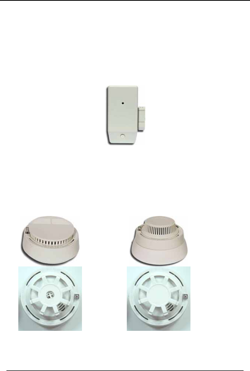
I.1.3. Magnetic Contact Sensor
This is a very special transmitter (Figure 3) for protecting windows, doors, closets and
drawers with a local magnetic sensor, and terminal blocks for wiring additional wired
magnetic sensors in series. A single transmitter can protect more than one door.
Figure 14 SA-02 Magnetic Contact Detector
I.1.4. Glass Break Detector
This special detector (Figure 4) is used to protect windows and glass walls; it is
especially suitable for balcony sliding glass windows, gazebo glass areas, and ordinary
glass windows. This detector detects an intruder before they actually enter––when
they break the glass. The SA-19 device provides superior audio analysis and false
alarm prevention by detecting both the shock wave at low frequencies, and the glass
breaking frequencies.
Figure 15 SA-19 Wireless Glass Break Detector
ACCESSORIES
HomeLogiX Installer Manual Page 42
I.1.5. Universal Wire to RF (Two-Channel) Transmitter
This special transmitter (Figure 5) was developed for interfacing with advanced
sensors––such as microwave barriers, infrared barriers––fence perimeter protection
detectors, and other third-party active detectors that produce a normally closed (NC)
or normally opened (NO) output. The SA-25 has pulse counting on one of the inputs
and can count 3, 6 or 9 pulses––programmable in that mode. The SA-25 itself is
powered from a battery, though it may also be powered from a dc power supply,
saving the battery for backup. This universal detector features a local magnetic
contact detector as well, and is supplied with PC utility software to simplify
programming.
Figure 16 SA-25 Wireless Universal Two Channel Transmitter
I.1.6. Smoke and Heat Detectors
There are four types of sensors in this category (Figure 6), which are connected to a
wireless transmitter base. The family of detectors consists of an Optical Smoke
Detector, an Ionization Smoke Detector, a Maximum-Temperature Detector, and a
Rate-of- Temperature-Rise Detector. These detectors report status to the control
panel, including tamper, low battery, alarms and alarm restore. The battery requires
replacement every year.
SA-15
SA-14
SA-17
SA-16
Figure 17 Wireless Smoke and Heat Detectors
I.2 HomeLogiXTM Compatible Remotes
A wide assortment of wireless remote control devices are available for use with the
HomeLogiXTM control panel. These are primarily used to set the control panel modes,
ACCESSORIES
HomeLogiX Installer Manual
Page 43
and for personal emergency applications. These transmitters can be enrolled onto
the HomeLogiXTM.
Note:
For the model numbers shown below, XX identifies a particular frequency and
country of application. Each detector is supplied with its own installation manual.
All the wireless remote controls are powered with standard available AAA or M2
alkaline primary cells, which have long battery life and are easily replaced.
The control panel identifies the detectors by means of a unique three-byte
identification code (ID Code), which offers up to 16 million possible combinations. The
ID is transmitted with every radio message. In addition to the ID, each detector
provides local intelligence by radio link to the panel of events such as:
• Away Arming (Full Arming Mode);
• Home Arming (Partial Arming Mode);
• Disarming (Not Armed Mode);
• Personal Panic Emergency.
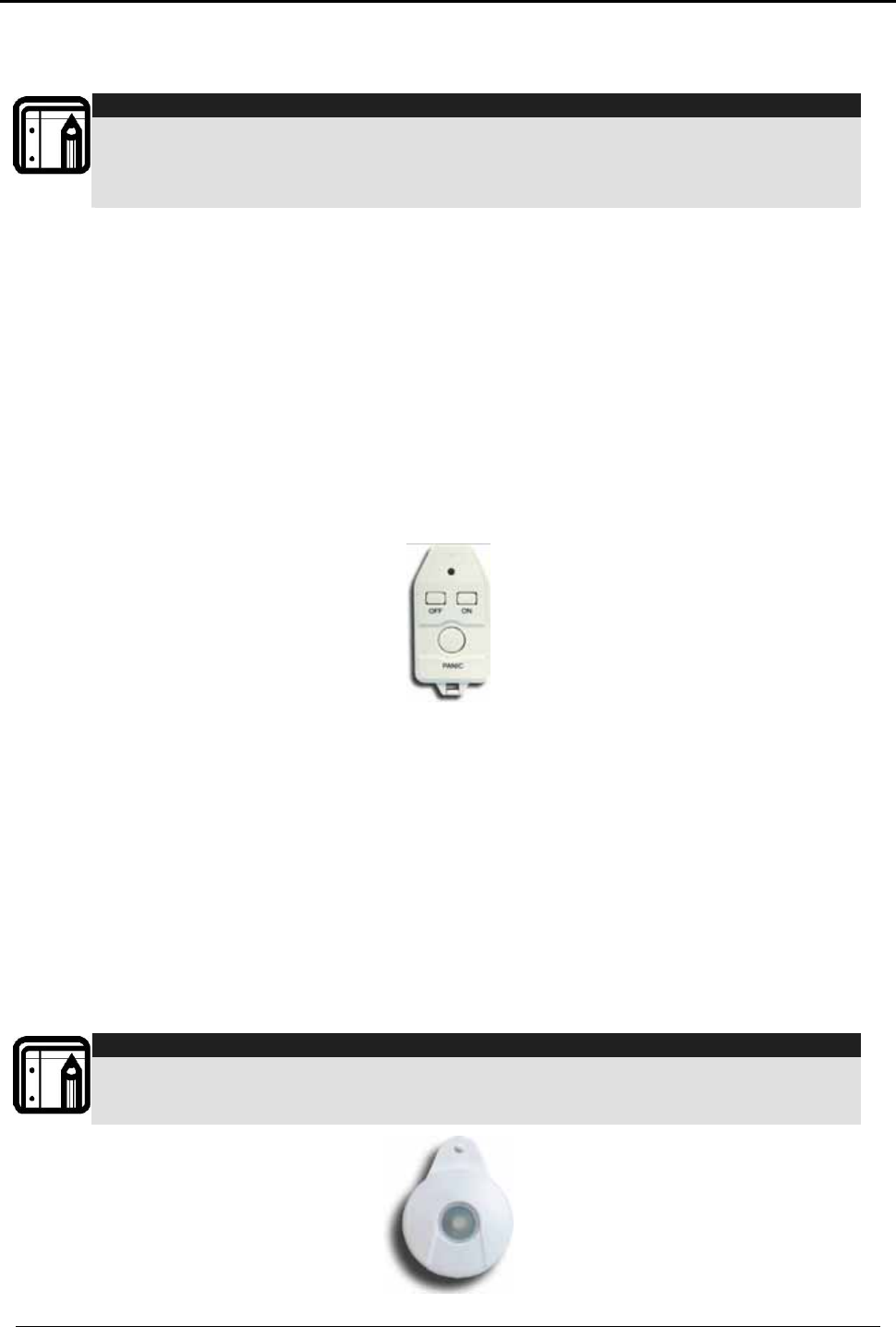
I.2.1. Wireless 3-Button Remote Control Transmitter
This hand-held transmitter (Figure 7) comes with a keychain attachment, and is small
enough to fit easily into a purse or pocket, to be carried around by the user.
Figure 18 SA-03 Wireless 3-Button Keychain Remote
Upon arriving at the armed house, the user presses a single button to disarm the house
without approaching the panel. Designed for comfortably using the system, the
transmitter can also fully arm the panel (Away Arm), or partially arm zones (Home
Arm). For emergencies, there is a Panic key, which when pressed for 2 seconds,
causes the panel to Alarm, regardless of whether the panel is armed or disarmed.
I.2.2. Wireless Emergency Panic Pendant
This is a very special transmitter (Figure 8) for emergency use. Because of its small size,
it can easily be carried by the user as a pendant. The SA-04 XX features waterproof
construction, which means the user can shower or bathe with it and can press the
button for 2 seconds to cause an Emergency Alarm at any time, 24 hours a day, in
both Armed and Disarmed modes.
Note:
This transmitter battery is not installer-
replaceable; it can be replaced in the factory.
Each SA-04 transmitter’s battery life is up to 5 years, based on 10 emergency
transmissions per year
Figure 19 Wireless Panic Pendant SA-04

ACCESSORIES
HomeLogiX Installer Manual Page 44
I.2.3. 1, 2 or 4-Button Remote Controls
These hand-held transmitters (see Figure 9) come with a belt-clip attachment and a
loop-clip attachment, so they can be hung on a wall or carried by the user on the
belt, or car visor.
The user arrives at the armed house and disarms the house by pressing a single button,
without any need to be near the panel. Designed for comfortable use of the system,
the transmitter can also fully arm (Away Arm) the panel, or partially arm zones (Home
Arm). For emergencies, there is a Panic key, which when pressed for 2 seconds,
causes the panel to Alarm, regardless of whether the panel is armed or disarmed.
SA-26
1-button Remote
SA-27
2-button Remote
SA-28
4-button Remote
Figure 20 Wireless Remote Control Transmitters
I.2.4. HomeLogiXTM Compatible Wireless Siren
Each HomeLogiXTM Control Panel can enroll and control up to four wireless sirens,
which can be installed on the exterior of the house, building or door of the premises.
The intrusion sound of the wireless sirens warns off attempting intruders and draws the
attention of neighbors, and directs emergency services to the location of the alarm.
The wireless sirens act in the same way as the panel alarm settings, with the same siren
time. When the panel is in alarm, the remote sirens will sound. For Silent Alarm, the
sirens will not sound. When the panel is disarmed, or the siren time expires, the sirens
will be remotely switched off by the panel.
I.3 Other HomeLogiXTM Accessories
Contact your dealer to ask for a current list of any accessories, parts and system
components not covered in this Installation Manual.
SENSOR PLACEMENT and HELPFUL REFERENCE TABLES
HomeLogiX Installer Manual
Page 45
Annex II. SENSOR PLACEMENT and HELPFUL
REFERENCE TABLES
II.1 Default Zone Descriptions
Attic Fire Main Entrance
Back Door Front Yard Master Bathroom
Back Yard Garage Master Bedroom
Basement Garage Door Office
Bathroom Gate Storage Room
Bedroom Guest Room Store
Child’s Room Guest Bathroom Upper Bathroom
Closet Hall Upstairs
Den Kitchen Vehicle Door
Dining Room Laundry Room Walkway
Downstairs Library Warehouse
Elevator Living Room Yard Door
Emergency Lower Bathroom
II.2 Custom Zone Descriptions
Custom Zone Description
Custom #1
Custom #2
Custom #3
Custom #4
Custom #5
II.3 Detector Deployment Plan
Zone
No. Zone Type Description Chime
Yes/No
No Activity
Zone PGM
1 PGM
2 Remarks
1.
2.
3.
4.
5.
6.

SENSOR PLACEMENT and HELPFUL REFERENCE TABLES
HomeLogiX Installer Manual Page 46
Zone
No. Zone Type Description Chime
Yes/No
No Activity
Zone PGM
1 PGM
2 Remarks
7.
8.
9.
10.
11.
12.
13.
14.
15.
16.
17.
18.
19.
20.
21.
22.
23.
24.
25.
26.
27.
28.
29.
30.
31.
32.
33.
34.
35.
36.
37.
38.
39.
40.

SENSOR PLACEMENT and HELPFUL REFERENCE TABLES
HomeLogiX Installer Manual
Page 47
II.4 Remote Control
No. Holder Name Normal
Operation PGM 1 PGM 2 Status Request
1.
2.
3.
4.
5.
6.
7.
8.

Reporting codesREPORTING CODES
HomeLogiX Installer Manual Page 48
Annex III. REPORTING CODES
III.1 Reporting codes
The Table below provides a listing of the codes used to communicate with the CMS.
Code Index Programmable Feature Description CID Code
01 Burglary Event (Alarm for a zone) E130
02 Burglary Restore (for a zone) R130
03 Fire Event (Fire Alarm for a zone or from emergency button) E110
04 Fire Restore (Fire Alarm for a zone or from emergency button) R110
05 24 Hour zone Audible Alarm Event E133
06 24 Hour zone Audible Alarm Restore R133
07 24 Hour zone Silent Alarm Event E122
08 24 Hour zone Silent Alarm Restore R122
09 Wire Sensor Tamper Event (Zone Tamper Alarm) E144
0A Wire Sensor Tamper Restore (Zone Tamper Alarm) R144
0B Wireless Sensor Tamper Event (alarm for RF zone) E383
0C Wireless Sensor Tamper Restore (for RF zone) R383
0D RF Low Battery Event (for RF zone) E384
0E RF Low Battery Restore (for RF zone) R384
0F Loss of supervision – RF Alarm Event (for a zone) E381
10 Loss of supervision – RF Restore (for a zone) R381
11 Wireless Panic Alarm Event From Remote Control E120
12 Sensor Trouble Event (No Activity Alarm) E380
13 Sensor Trouble Restore (No Activity Alarm) R380
14 Duress Report Event R121
15 Open Report Event (Disarm) E401
16 Close Report Event (Arm Away) R401
17 Partial Close Report Event (Arm Home) E456
18 Keys-witch O/C (Key-Switch Disarm) R409
19 Keys-witch O/C (Key-Switch Arm Away) E409
1A Keys-witch O/C (Key-Switch Arm Home) E442
1B Cancel Event (Alarm Cancel Report) E406
1C Silent Panic From Panel E122
1D Audible Panic From Panel E123
1E Quick Arm E408
1F Forced Arm E423
20 Remote arm/disarm (Disarm) R407
21 Remote arm/disarm (Arm) E407
22 RF receiver Jam Detect Event E344
23 RF receiver Jam Detect Restore R344
24 Low system battery Event (Panel Low Battery) E302
25 Low system battery Restore (Panel Low Battery) R302
26 AC Loss Event (Panel AC Failure) E301
27 AC Loss Restore (Panel AC Failure) R301
28 Tamper Event (Panel Tamper) E137
29 Tamper Restore (Panel Tamper) R137
2A Failure to communicate Event (Communication Failure) E354
2B Zone bypass Event E570
2C Zone bypass Restore R570

Reporting codesREPORTING CODESReporting codes
HomeLogiX Installer Manual
Page 49
Code Index Programmable Feature Description CID Code
2D Periodic Test Report Event E602
---* Listen in Follow - E606
*This event is not sent by the panel to the dialer. Listen in Follow code is produced by
the dialer according to current configuration:
• 2-way voice enable/disable
• 2-way voice period,
Therefore there is no Index.

Limited WarrantyLIMITED WARRANTY
HomeLogiX Installer Manual Page 50
Annex IV. LIMITED WARRANTY
IV.1 Limited Warranty
ROSSLARE ENTERPRISES LIMITED S (Rosslare) TWO YEARS LIMITED WARRANTY is applicable worldwide. This warranty
supersedes any other warranty. Rosslare's TWO YEARS LIMITED WARRANTY is subject to the following conditions:
Warranty
Warranty of Rosslare's products extends to the original purchaser (Customer) of the Rosslare product and is not transferable.
Products Covered By This Warranty and Duration
ROSSLARE ENTERPRISES LTD. AND / OR SUBSIDIARIES (ROSSLARE) warrants that the HomeLogiXTM Advanced Wireless
Intrusion system panel, to be free from defects in materials and assembly in the course of normal use and service. The warranty period
commences with the date of shipment to the original purchaser and extends for a period of 2 years (24 Months).
Warranty Remedy Coverage
In the event of a breach of warranty, ROSSLARE will credit Customer with the price of the Product paid by Customer, provided that the
warranty claim is delivered to ROSSLARE by the Customer during the warranty period in accordance with the terms of this warranty.
Unless otherwise requested by ROSSLARE ENTERPRISES LTD. AND / OR SUBSIDIARIES representative, return of the failed
product(s) is not immediately required.
If ROSSLARE has not contacted the Customer within a sixty (60) day holding period following the delivery of the warranty claim,
Customer will not be required to return the failed product(s). All returned Product(s), as may be requested at ROSSLARE
ENTERPRISES LTD. AND /OR SUBSIDIARY’S sole discretion, shall become the property of ROSSLARE ENTERPRISES LTD. AND
/OR SUBSIDIARIES.
To exercise the warranty, the user must contact Rosslare Enterprises Ltd. to obtain an RMA number after which, the product must be
returned to the Manufacturer freight prepaid and insured
In the event ROSSLARE chooses to perform a product evaluation within the sixty (60) day holding period and no defect is found, a
minimum US$ 50.00 or equivalent charge will be applied to each Product for labor required in the evaluation.
Rosslare will repair or replace, at its discretion, any product that under normal conditions of use and service proves to be defective in
material or workmanship. No charge will be applied for labor or parts with respect to defects covered by this warranty, provided that the
work is done by Rosslare or a Rosslare authorized service center.
Exclusions and Limitations
ROSSLARE shall not be responsible or liable for any damage or loss resulting from the operation or performance of any Product or any
systems in which a Product is incorporated. This warranty shall not extend to any ancillary equipment not furnished by ROSSLARE,
which is attached to or used in conjunction with a Product, nor to any Product that is used with any ancillary equipment, which is not
furnished by ROSSLARE.
This warranty does not cover expenses incurred in the transportation, freight cost to the repair center, removal or reinstallation of the
product, whether or not proven defective.
Specifically excluded from this warranty are any failures resulting from Customer's improper testing, operation, installation, or damage
resulting from use of the Product in other than its normal and customary manner, or any maintenance, modification, alteration, or
adjustment or any type of abuse, neglect, accident, misuse, improper operation, normal wear, defects or damage due to lightning or
other electrical discharge. This warranty does not cover repair or replacement where normal use has exhausted the life of a part or
instrument, or any modification or abuse of, or tampering with, the Product if Product disassembled or repaired in such a manner as to
adversely affect performance or prevent adequate inspection and testing to verify any warranty claim.
ROSSLARE does not warrant the installation, maintenance, or service of the Product. Service life of the product is dependent upon the
care it receives and the conditions under which it has to operate.
In no event shall Rosslare be liable for incidental or consequential damages.
Limited Warranty Terms
THIS WARRANTY SETS FORTH THE FULL EXTENT OF ROSSLARE ENTERPRISES LTD. AND IT’S SUBSIDIARIES’ WARRANTY
THE TERMS OF THIS WARRANTY MAY NOT BE VARIED BY ANY PERSON, WHETHER OR NOT PURPORTING TO REPRESENT OR ACT
ON BEHALF OF ROSSLARE.
THIS LIMITED WARRANTY IS PROVIDED IN LIEU OF ALL OTHER WARRANTIES. ALL OTHER WARRANTIES EXPRESSED OR IMPLIED,
INCLUDING WITHOUT LIMITATION, IMPLIED WARRANTIES OF MERCHANTABILITY AND FITNESS FOR A PARTICULAR PURPOSE, ARE
SPECIFICALLY EXCLUDED.
IN NO EVENT SHALL ROSSLARE BE LIABLE FOR DAMAGES IN EXCESS OF THE PURCHASE PRICE OF THE PRODUCT, OR FOR ANY
OTHER INCIDENTAL, CONSEQUENTIAL OR SPECIAL DAMAGES, INCLUDING BUT NOT LIMITED TO LOSS OF USE, LOSS OF TIME,
COMMERCIAL LOSS, INCONVENIENCE, AND LOSS OF PROFITS, ARISING OUT OF THE INSTALLATION, USE, OR INABILITY TO USE
SUCH PRODUCT, TO THE FULLEST EXTENT THAT ANY SUCH LOSS OR DAMAGE MAY BE DISCLAIMED BY LAW.
THIS WARRANTY SHALL BECOME NULL AND VOID IN THE EVENT OF A VIOLATION OF THE PROVISIONS OF THIS LIMITED
WARRANTY.

TECHNICAL SUPPORT
HomeLogiX Installer Manual
Page 51
Annex V. TECHNICAL SUPPORT
Asia Pacific, Middle East, Africa
Rosslare Security Products Headquarters
905-912 Wing Fat Industrial Bldg,
12 Wang Tai Road,
Kowloon Bay Hong Kong
Tel: +852 2795-5630
Fax: +852 2795-1508
E-mail: support.apac@rosslaresecurity.com
United States and Canada
1600 Hart Court, Suite 103
Southlake, TX, USA 76092
Toll Free: +1-866-632-1101
Local: +1-817-305-0006
Fax: +1-817-305-0069
E-mail: support.na@rosslaresecurity.com
Europe
Global Technical Support & Training Center
HaMelecha 22
Rosh HaAyin, Israel 48091
Tel: +972 3 938-6838
Fax: +972 3 938-6830
E-mail: support.eu@rosslaresecurity.com
South America
Pringles 868, 1640 Martinez
Buenos Aires
Argentina
Tel: +54 11 4798-0095
Fax: +54 11 4798-2228
E-mail: support.la@rosslaresecurity.com
Web Site: www.rosslaresecurity.com

0706-0960328+00
www.rosslaresecurity.com