Rothenbuhler Engineering 1678-4 Test Box User Manual
Rothenbuhler Engineering Company Inc Test Box Users Manual
Users Manual
REMOTE FIRING DEVICE
OPERATION MANUAL
The information contained in this document is subject to change
without notice. In no event shall Rothenbuhler Engineering
Company be liable for errors contained herein or for special,
indirect, or consequential damages or injuries of any nature
resulting from use of information in this document.
ROTHENBUHLER ENGINEERING
P.O. BOX 708
524 RHODES ROAD
SEDRO WOOLLEY, WA 98284
1678-A16 {Draft}
5/12/2011
©2011 Rothenbuhler Engineering
All Rights reserved
SPECIAL NOTICE
WARNING TO USERS AND AFFECTED PERSONS
The Remote Firing Device (RFD) is designed to be used in blasting operations.
Explosives used in connection with the RFD may be extremely powerful. Improper use
of explosives with or without the RFD or improper safety precautions taken with respect
to personnel or property may result in death, serious personal injury, or property
damage. Other manufacturers’ equipment that may not be in compliance with
frequency coordination may inadvertently interfere with the operation of the RFD. Be
aware of other operations within the receiving range of the RFD.
The literature accompanying this warning contains information of a general nature for
users of the RFD based upon the manufacturer’s experience in the design and
manufacture of remote radio frequency devices. In addition, the manufacturer provides
product literature and technical data sheets periodically which should be consulted for
detailed information on the characteristics, specifications and recommendations for the
RFD. The manufacturer does not purport to give information or advice on explosives or
their use.
The RFD and related explosive devices are intended for use only by trained
professionals having comprehensive knowledge of the RFD, the explosives being used,
and the application together with all related safety precautions. The manufacturer of the
RFD is responsible only for the proper performance of the RFD itself and is not
responsible for the performance, safety, or specifications of the explosive used, nor the
suitability of the RFD for any particular purpose other than that expressly described in
the manufacturer’s literature.
LIMITED WARRANTY
The manufacturer warrants the Model 1678 Remote Firing Device (RFD) to be free of
defects in workmanship or materials for the period of one year from the date of
purchase. In the event any RFD or component thereof is shown to be defective in
workmanship or materials within one year, the system or component will be repaired or
replaced without charge by the manufacturer at the manufacturer’s place of business.
This warranty does not cover damage or injury to equipment resulting from abuse,
neglect, or use in applications other than expressly described by the manufacturer as fit
purposes for the RFD.
This Limited Warranty is given in lieu of all other legal warranties express or implied and
neither the manufacturer nor its representatives shall be liable for any direct, incidental
or consequential loss or damages arising out of any occurrence or accident involving
the use of this product.
1678 RFD OPERATION MANUAL {DRAFT} ii

FCC NOTICE
This device complies with Part 15 of the FCC regulations. Operation is subject to the
following two conditions: (1) That this device may not cause harmful interference, and
(2) this device must accept any interference received, including interference that may
cause undesired operation.
RADIATION HAZARD WARNING
This radio shall only be used during the course of employment by individuals aware of
the hazards of radio frequency (RF) radiation exposure, and the ways to minimize such
hazards. This radio is not intended for use by the "General Population." Further, this
radio must not be co-located or operated in conjunction with any other antenna or
transmitter. User should not allow antennas to come within 20 cm (8 inches) of the body
during use.
CANADA
**This Class B digital apparatus meets all requirements of the Canadian Interference-
Causing Equipment Regulations.
Cet appareil numérique de la classe B respecte toutes les exigences du Règlement sur
le matériel brouilleur du Canada.
Under Industry Canada regulations, this radio transmitter may only operate using an
antenna of a type and maximum (or lesser) gain approved for the transmitter by Industry
Canada. To reduce potential radio interference to other users, the antenna type and its
gain should be so chosen that the equivalent isotropically radiated power (e.i.r.p.) is not
more than that necessary for successful communication.
This radio transmitters (IC: 2758A-166921 and 2758A-16784) have been approved by
Industry Canada to operate with the antenna types listed below with the maximum
permissible gain and required antenna impedance for each antenna type indicated.
Antenna types not included in this list, having a gain greater than the maximum gain
indicated for that type, are strictly prohibited for use with this device.
Antenna: ¼ wave whip, gain 2.15 dBi
1678 RFD OPERATION MANUAL {DRAFT} iii
Conformément à la réglementation d'Industrie Canada, le présent émetteur radio peut
fonctionner avec une antenne d'un type et d'un gain maximal (ou inférieur) approuvé
pour l'émetteur par Industrie Canada. Dans le but de réduire les risques de brouillage
radioélectrique à l'intention des autres utilisateurs, il faut choisir le type d'antenne et son
gain de sorte que la puissance isotrope rayonnée équivalente (p.i.r.e.) ne dépasse pas
l'intensité nécessaire à l'établissement d'une communication satisfaisante.
Le présent émetteur radio (IC: 2758A-166921 and 2758A-16784) a été approuvé par
Industrie Canada pour fonctionner avec les types d'antenne énumérés ci-dessous et
ayant un gain admissible maximal et l'impédance requise pour chaque type d'antenne.
Les types d'antenne non inclus dans cette liste, ou dont le gain est supérieur au gain
maximal indiqué, sont strictement interdits pour l'exploitation de l'émetteur.
Stabantenne: ¼ longueur d'onde, gain 2.15 dBi
1678 RFD OPERATION MANUAL {DRAFT} iv
TABLE OF CONTENTS
Chapter Page
SPECIAL NOTICE .......................................................................................................... II
WARNING TO USERS AND AFFECTED PERSONS .................................................... II
LIMITED WARRANTY....................................................................................................II
FCC NOTICE ................................................................................................................. III
RADIATION HAZARD WARNING.................................................................................III
CANADA........................................................................................................................ III
TABLE OF CONTENTS..................................................................................................V
LIST OF ILLUSTRATIONS..........................................................................................VIII
SAFETY INFORMATION................................................................................................X
1. INTRODUCTION.................................................................................................. 1
1.1. Purpose ............................................................................................................ 1
1.2. Storage and Environmental Conditions............................................................. 1
1.3. Maintenance ..................................................................................................... 3
2. INTRODUCTION TO RFD SYSTEM COMPONENTS ......................................... 4
2.1. System.............................................................................................................. 4
2.2. Mini Controller Unit ........................................................................................... 7
2.3. Mini Controller Unit Switch Operation ............................................................... 7
2.4. Mini Controller Unit Display Operation ............................................................ 10
2.5. Electric Remote Unit ....................................................................................... 13
2.6. Remote Shock Tube Initiator (RSTI) ............................................................... 16
2.7. 3 Position Battery Charger.............................................................................. 19
2.8. Test Box.......................................................................................................... 19
1678 RFD OPERATION MANUAL {DRAFT} v
2.9. Antenna Assembly .......................................................................................... 21
2.10. Carrying Case ............................................................................................. 22
2.11. Vent operation ............................................................................................. 25
2.12. Antenna / Battery Charger Connector ......................................................... 26
2.13. Connector Dust Cover Operation ................................................................ 27
3. SYSTEM SPECIFICATIONS.............................................................................. 28
3.1. Radio .............................................................................................................. 28
3.2. Physical .......................................................................................................... 29
3.3. Battery ............................................................................................................ 29
3.4. Timing ............................................................................................................. 30
3.5. Detonate Output.............................................................................................. 30
3.6. System Identification....................................................................................... 31
4. PRE-OPERATIONAL PROCEDURES............................................................... 32
4.1. Physical Inspection ......................................................................................... 32
4.2. Battery Charging With the 3-Position Charger ................................................ 32
4.3. Bench Testing the System .............................................................................. 34
5. OPERATIONAL PROCEDURES ....................................................................... 36
5.1. Ready the System at Site ............................................................................... 36
5.2. Placement of Remote Units ............................................................................ 37
5.3. System Operation – Remote Units Within 1 mile of Mini Controller Unit......... 38
5.4. System Operation – Remote Units More Than 1 mile From Mini Controller Unit
40
5.5. System Operation – Remote Units Both Within and In Excess of 1 mile and
Less Than 5 miles from Mini Controller Unit ............................................................. 41
6. POST OPERATIONAL PROCEDURES ............................................................ 44
6.1. Securing the System....................................................................................... 44
6.2. Physical Inspection ......................................................................................... 44
6.3. Packaging ....................................................................................................... 44
1678 RFD OPERATION MANUAL {DRAFT} vi
6.4. Maintenance & Equipment Storage ................................................................ 44
7. BASIC TROUBLESHOOTING IN THE FIELD................................................... 45
7.1. Remote Units .................................................................................................. 45
7.2. Mini Controller Unit ......................................................................................... 45
7.3. Remote Shock Tube Initiator........................................................................... 45
8. OPTIMIZING RANGE......................................................................................... 47
9. TEST BOX.......................................................................................................... 52
9.1. Test Box Descriptions ..................................................................................... 52
9.2. Test Box Operation ......................................................................................... 53
9.3. Saving Test Box results to a file using HyperTerminal.................................... 61
10. RFD PROGRAMMING GUIDE........................................................................... 68
10.1. Programmable Parameters ......................................................................... 68
10.2. Required equipment .................................................................................... 68
10.3. Windows Configuration Software Operation (Setup RFD)........................... 68
10.4. Setup RFD Installation ................................................................................ 68
10.5. Configuring Setup RFD ............................................................................... 70
10.6. Using Setup RFD to Test RFD Units ........................................................... 71
10.7. Using Setup RFD to Program RFD Units .................................................... 76
11. BATTERY MAINTENANCE ............................................................................... 81
11.1. Battery Temperature ................................................................................... 81
11.2. Pre-operation............................................................................................... 81
11.3. Periodic ....................................................................................................... 81
11.4. Annual ......................................................................................................... 81
11.5. Extended non-use ....................................................................................... 81
1678 RFD OPERATION MANUAL {DRAFT} vii
LIST OF ILLUSTRATIONS
Figure 2-1 RFD 4-Remote Case System......................................................................... 6
Figure 2-2 Mini Controller Unit ........................................................................................ 7
Figure 2-3 Mini Controller Isometric View with Antenna ................................................ 12
Figure 3-1 Electric Remote Unit .................................................................................... 13
Figure 3-2 Electric Remote Unit Angled View ............................................................... 15
Figure 3-3 Remote Shock Tube Initiator (RSTI) ............................................................ 16
Figure 3-4 RSTI Angled View with Shock Tube Spark Tip ............................................ 17
Figure 3-5 Shock Tube Tip............................................................................................ 18
Figure 3-7 3 POSITION CHARGER .............................................................................. 19
Figure 3-8 Test Box....................................................................................................... 20
Figure 3-9 Antenna Assembly ....................................................................................... 22
Figure 3-10 Carrying Case ............................................................................................ 23
Figure 3-11 Carrying Case (Half Case) ......................................................................... 24
Figure 3-12 Vent Operation........................................................................................... 25
Figure 3-13 3-Position Charger Connection .................................................................. 26
Figure 3-14 Connector Dust Cover Operation............................................................... 27
Figure 4-1 Mini Controller Unit Identification Label........................................................ 31
Figure 4-2 Remote Unit Front Identification Label......................................................... 31
Figure 9-1 Unit Normal Transmission Location ............................................................. 48
Figure 9-2 Remote Unit Elevated .................................................................................. 49
Figure 9-3 Mini Controller Unit Elevated........................................................................ 50
Figure 9-4 Antenna Radiation Pattern ........................................................................... 51
1678 RFD OPERATION MANUAL {DRAFT} viii

SAFETY INFORMATION
The following are WARNINGS and CAUTIONS, contained throughout this manual and
are repeated here for emphasis. All personnel engaged in the handling, firing, and
storage of the system covered in this manual must fully understand these WARNINGS
and CAUTIONS, and procedures by which hazardous conditions are to be reduced or
eliminated. Also listed are general safety precautions that are not related to any specific
procedures and therefore don't appear elsewhere in this publication. These are
recommended precautions that personnel must understand and apply during many
phases of operation and maintenance.
WARNING Never rely on the equipment for your safety.
WARNING Use of this system and its components must be restricted to personnel
qualified and experienced in the field of explosives and detonating devices. Under no
circumstances shall untrained personnel attempt to use this manual as a text for self-
teaching.
WARNING This system and its components should be stored in a secure area with
no access to unauthorized personnel. This system can be used in conjunction with
explosives as a deadly weapon.
WARNING These radios contain batteries. The potential for activation is always
present whether or not antennas are attached to the units.
WARNING Employ standard blasting system safety standards when using this
equipment with explosives.
WARNING Lightning induced energy, caused by electrical storms, can detonate
explosives. In the interest of safety, blasting on land, water and underground should be
suspended and all personnel should be evacuated to a safe distance from the blast
area whenever lightning storms are in the vicinity. Dangerous levels of static electricity
can build up in the atmosphere. These levels can be sufficient to detonate explosives.
WARNING Radio frequency energy of sufficient magnitude can cause blasting
caps to detonate.
WARNING To eliminate long wire runs, and to make the "shoot" from a safe
distance, the Remote Firing Device uses low energy level radio frequency
transmissions.
WARNING Do not connect a blasting cap to a Remote Unit unless the green
SAFE light is on, the red ARMED light is off, and the yellow ON/LOW BATT light is on
steady. This indicates there is no voltage on the binding posts, the binding posts are
electically isolated from the firing capacitor, the binding posts are shunted to each other,
and the battery is not low.
1678 RFD OPERATION MANUAL {DRAFT} x

WARNING Ensure that blasting caps are not connected to any of the Remote
Units during bench testing.
WARNING This is a sensitive electronic radio system and it may be damaged.
WARNING Do not use the Mini Controller Unit within 100 feet (30 meters) of
explosives, blasting caps, or wires leading to them. The Mini Controller signal is 5 watts,
which can cause detonation of caps if within 100 feet. The 5 watt Mini Controller
complies with the Recommended Table of Distances established by the Institute for the
Makers of Explosives (IME) when placed beyond 100 feet of explosives.
WARNING Do not engage in RFD communications with the Remote Units when
they are connected to explosive charges until the shot is prepared and all personnel are
clear. The Remote Unit complies with the Recommended Table of Distances
established by the Institute for the Makers of Explosives (IME) when placed 25 feet (8
meters) or more from blasting caps or wires leading to them. For further information,
refer to the Institute for the Makers of Explosives Publication no. 20, Part II, Section (1).
WARNING Do not touch the Shock Tube Tip Jacks on the side of the Remote
Shock Tube Initiator (RSTI) when armed or firing. Lethal voltages may be present.
CAUTION Do not assume the Disarm command has been received by the
Remote Unit unless DISARMED status is confirmed with a steady DISARMED light for
that Remote Unit on the Mini Controller Unit display panel. If distance appears to be the
problem, move closer to the Remote Unit following standard procedures for this type of
situation. The “STATUS” and/or “DISARM” switches may be pressed repeatedly as the
Remote Unit is approached. Maintain a safe distance from the Remote Unit. Do not
approach the Remote Unit until DISARMED status is confirmed with a steady
DISARMED light for that Remote Unit on the Mini Controller Unit display panel. Under
no conditions should the “FIRE” switch be pressed as the Remote Unit is approached.
DO NOT bring the Mini Controller Unit closer than 100 feet (30 meters) to blasting caps,
wires connected to blasting caps, or other explosives.
CAUTION All units must be thoroughly tested and the batteries fully charged prior
to operational use.
CAUTION Unequal air pressure inside the Mini Controller Unit may affect the
operation of membrane switch keypad. Extreme pressure differentials may irreversibly
damage the keypad and/or cases.
CAUTION Vents in all units should be momentarily opened and closed
immediately before use.
CAUTION Do not open a vent if there is water on or near the vent. Keep the vents
closed when the relative humidity is above 90%. Take necessary precautions to ensure
moisture does not enter the unit case.
1678 RFD OPERATION MANUAL {DRAFT} xi
1678 RFD OPERATION MANUAL {DRAFT} xii
CAUTION Do not use any component that is damaged, suspected of being
damaged, or is not able to operate as designed. The safety of the operation could be
compromised.

1. INTRODUCTION
1.1. PURPOSE
1.1.1.
1.1.2.
1.1.3.
The primary purpose of this manual is to provide descriptive information,
operational information, instructions in assembly, and instructions in testing and
preparation for operational or training use of the Remote Firing Device (RFD).
The Remote Firing Device (RFD) is used to activate electric and non-electric
detonator devices. The System is strictly an electronic device, containing no explosive.
The Mini Controller Unit shall be operated from 100 feet (30 meters) to five miles (8 km)
from the explosive. The Electric Remote Unit shall be placed at the explosive site, with
a two-conductor firing line running to the explosive. The Remote Shock Tube Initiator
(RSTI) is placed at the explosive site, with 3mm non-electric shock tube running to the
explosive. The Mini Controller Unit communicates to the Remote Units through a two-
way RF transmitter data link, for a typical distance greater than Error! Reference
source not found. (8 km). The Remote Unit can typically return communication for a
distance greater than Error! Reference source not found. (1.6 km). Actual
communication range is dependant upon a variety of factors such as terrain, obstacles,
antenna height, and local interference.
Throughout this manual, the tem “Remote Unit” is a generic term that is used
for both the Electric Remote Unit and for the RSTI.
1.2. STORAGE AND ENVIRONMENTAL CONDITIONS
1.2.1.
1.2.2.
1.2.3.
1.2.4.
1.2.5.
The Mini Controller Unit and Remote Unit have manual operated vents. The
vents should always be CLOSED during air transport, underwater transport, storage
and operational use to prevent moisture intake. The operator should momentarily open
and close the vent after the unit has been subjected to changes in elevation or depth.
This equalizes pressure within the case to the outside environment. DO NOT open the
vent if there is water on or near the vent or if the relative humidity is above 90%. Towel
dry vents prior to opening. The vents should be OPEN, when stored in a dry hot
environment.
The Mini Controller Unit and Remote Unit (with vents closed) are airtight to an
altitude of 30,000 feet and watertight to a depth of 100 feet.
The Mini Controller Unit and Remote Unit is shock resistant, drop tested from
5 feet onto 3 inches of steel plate backed by concrete.
The battery pack and unit electronics are electrically isolated from the unit
case.
The Mini Controller Unit and Electric Remote Unit have a temperature
operation from -22 ºF to +140 ºF (-30 ºC to +60 ºC). The RSTI has a temperature
1678 RFD OPERATION MANUAL {DRAFT} 1
operation range from -15 ºF to +140 ºF (-26 ºC to +60 ºC).
1678 RFD OPERATION MANUAL {DRAFT} 2

1.3. MAINTENANCE
1.3.1.
1.3.2.
1.3.3.
1.3.4.
Batteries within the RFD require periodic charging and discharging to
maintain health and service life.
The battery packs within the RFD should be replaced every 3 years or 300
charge cycles, whichever comes first. Battery packs can be replaced by the user
following strict procedures to maintain case sealing. It is recommended the battery
packs be replaced by the manufacturer or by an authorized service center. Contact the
manufacturer for details.
Corrective maintenance shall be accomplished at the manufacturer or
authorized service depot. Replacement of parts or disassembly by any other entity
could result in the unsafe operation of the RFD and will void the manufacturer’s
warranty.
In case of failure of a component of the RFD System, the system will need to
be shipped to the manufacturer or authorized service depot.
1678 RFD OPERATION MANUAL {DRAFT} 3

2. INTRODUCTION TO RFD SYSTEM COMPONENTS
2.1. SYSTEM
2.1.1.
2.1.2.
2.1.3.
2.1.4.
2.1.5.
2.1.6.
The RFD is a battery powered, hand held, radio remote controlled system to
be used on land as a primary firing mechanism to detonate explosive charges. The
RFD system consists of a Mini Controller Unit and up to four Remote Units (any
combination for Electric Remotes and RSTIs up to a total of four).
The Mini Controller Unit and Remote Units in one system will not operate with
Units from another system.
The RFD is transportable over land, underwater to a depth of 100 feet (30
meters), and in the air to an altitude of 30,000 feet (9,100 meters). The units are shock
resistant to a 5 foot (1.5 meter) drop and impervious to static discharge.
The Mini Controller and Electric Remote Units will operate in a temperature
range of -22 ºF to + 140 ºF (-30 ºC to +60 ºC). The RSTI will operate in a temperature
range of -15 ºF to +140 ºF (-26 ºC to +60 ºC).
The system has two modes of operation. The two modes are one-way, and
the two-way mode.
2.1.5.1. Range for one-way mode is greater than Error! Reference source not
found. (8 km) typically.
2.1.5.2. Range for two-way mode is greater than 1 mile (1.5 km) typically.
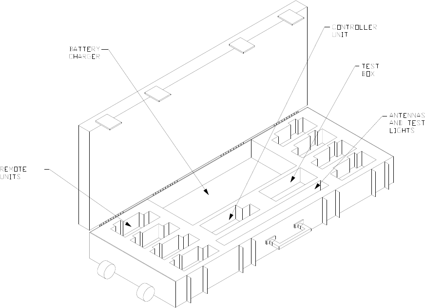
The RFD System consists of the component parts in Table 2-1 and Figure
2-1.
1678 RFD OPERATION MANUAL {DRAFT} 4

Table 2-1 RFD 4-Remote Case System
Figure Index No. Description Units per System
Figure 2-2 1 Mini Controller Unit 1
Figure 2-2 2 Remote Unit, Electric Up to 4*
Figure 2-2 3 Remote Unit, RSTI Up to 4*
Figure 2-2 4 Battery Charger See note **
Figure 2-2 5 Antenna Assembly One per Unit
Figure 2-2 6 Carrying Case Assembly 2
Figure 2-2 7 Test Box 1
Figure 2-2 8 Test Lamp 1 per Electric
Remote
Figure 2-2 9 Shock Tube Igniter Tip 2 per RSTI
* Any combination of Electric Remotes and Remote Shock Tube Initiators (RSTIs) can
be configured for a maximum total of 4 Remotes.
** The system is available with one or two 3-Position Chargers. Included with each
Charger is a +12V power supply.
1678 RFD OPERATION MANUAL {DRAFT} 5
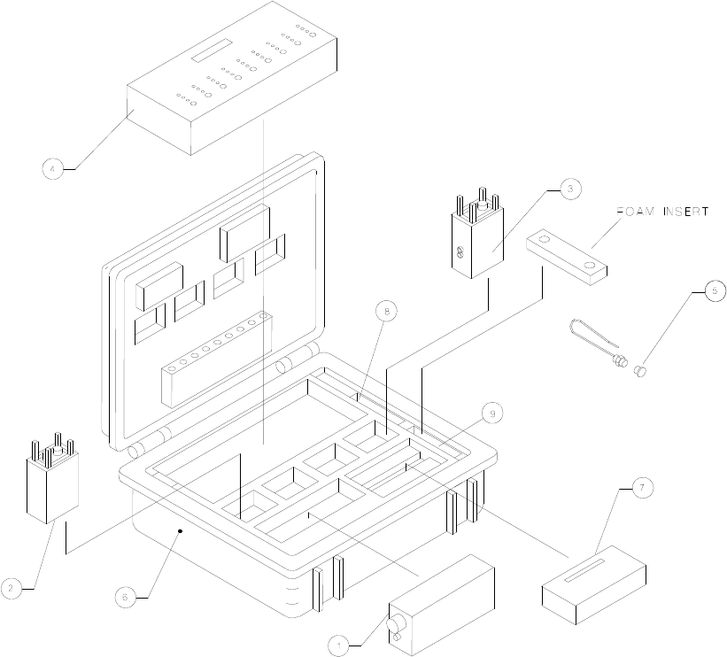
Figure 2-1 RFD 4-Remote Case System
1678 RFD OPERATION MANUAL {DRAFT} 6
2.2. MINI CONTROLLER UNIT
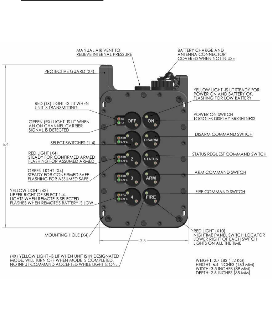
2.2.1. Figure 2-2 shows the external features of the Mini Controller Unit. The unit is
sealed at the manufacturer and/or service depot and should not be opened during field
activity.
Figure 2-2 Mini Controller Unit
2.3. MINI CONTROLLER UNIT SWITCH OPERATION
2.3.1. Unit Power Control: Depress the “ON” switch for one second to turn the
power on to the Mini Controller Unit when the Antenna is attached. The yellow light in
the upper left quadrant of the “ON” switch will turn on. Depress the “OFF” switch to turn
the power off to the Mini Controller Unit.
1678 RFD OPERATION MANUAL {DRAFT} 7
2.3.2.
2.3.3.
2.3.4.
2.3.5.
2.3.6.
Power ON Self Test: Upon installing the antenna and pressing the “ON”
switch, a rigorous self test is initiated. If a failure of the self test occurs, it will not be
possible to activate the unit. The unit must be returned to the Manufacturer for service.
Do not attempt to use a failing unit.
Display Panel Light Dimmer Circuit: With the unit powered on, Repress
the ‘ON’ switch briefly to toggle the LED display light’s intensity between bright and dim.
When the unit is turned on, the last chosen intensity setting is restored.
Select Remote Units: Depress the Select Switches “1” through “4” to select
independently the Remote Units that will communicate with the Mini Controller Unit.
Any combination of the four Remote Units may be selected. The yellow SELECT light
on the switch indicates if the Remote Unit programmed for that switch is selected.
Press the switch again and the yellow SELECT light for that Remote Unit will be turned
off indicating the Remote Unit is not selected.
Request Remote Unit Status: Depress the “STATUS” switch to transmit a
status request signal to the selected Remote Units. The selected Remote Units will
transmit their current status to the Mini Controller Unit. If none of the Remote Units are
selected, the Mini Controller Unit will request status from all four Remote Units. Any
answering Remote Units will be selected automatically. If the Mini Controller Unit is
within range of the Remote Unit transmitter, the status of the selected Remote Unit will
be presented on the display panel with a steady light. If the Mini Controller Unit is out of
range of the Remote Unit transmitter, the status will be assumed from the last command
sent to that Remote Unit. In that case the assumed status of the Remote Unit will flash
on the display panel.
Arm the Remote Unit: Depress the “ARM” switch for 1/2 second and the
Mini Controller Unit will transmit the Arm command to the selected Remote Units. The
red ARMED light at the selected Remote Units will flash on the Mini Controller Unit
display panel until the firing capacitor charging time is completed. The Mini Controller
Unit then requests status of the selected Remote Units. If the Mini Controller Unit is
within range of the selected Remote Unit transmitter, the ARMED red light for that
Remote Unit will be on steady on the Mini Controller Unit display panel. If the Mini
Controller Unit is out of range of the selected Remote Unit transmitter, the red ARMED
light for that Remote Unit will continue to flash on the Mini Controller Unit display panel.
If the Fire command is not sent within the Arm Time Period, the system will disarm
automatically.
1678 RFD OPERATION MANUAL {DRAFT} 8
2.3.7.
2.3.8.
2.3.9.
Disarm the Remote Unit: Depress the “DISARM” switch. The Mini
Controller Unit will transmit the Disarm command to selected Remote Units. Selected
Remote Units will internally discharge their firing capacitor. Selected Remote Units that
receive the Disarm command will become disarmed within 3 seconds of receiving the
command. The green DISARMED light for selected Remote Units will begin to flash on
the Mini Controller Unit display panel. The Mini Controller Unit will then request status
of selected Remote Units. If the Mini Controller Unit is within range of the selected
Remote Unit transmitter, the green DISARMED light for that Remote Unit will turn to
steady on the Mini Controller Unit display panel. If the Mini Controller Unit is out of
range of the selected Remote Unit transmitter, the green DISARMED light for that
Remote Unit will continue to flash on the Mini Controller Unit display panel. If the Fire
command is not sent within the Arm Time Period, the system will disarm automatically.
CAUTION Do not assume the Disarm command has been received by the Remote
Unit unless DISARMED status is confirmed with a steady DISARMED light for that
Remote Unit on the Mini Controller Unit display panel. If distance appears to be the
problem, move closer to the Remote Unit following standard procedures for this type of
situation. The “STATUS” and/or “DISARM” switches may be pressed repeatedly as the
Remote Unit is approached. Maintain a safe distance from the Remote Unit. Do not
approach the Remote Unit until DISARMED status is confirmed with a steady
DISARMED light for that Remote Unit on the Mini Controller Unit display panel. Under
no conditions should the “FIRE” switch be pressed as the Remote Unit is approached.
DO NOT bring the Mini Controller Unit closer than 100 feet (30 meters) to blasting caps,
wires connected to blasting caps, or other explosives.
Activate the Remote Unit Firing Circuit: Depress the “FIRE” switch for 1/2
second and the Mini Controller Unit will transmit the Fire command to selected Remote
Units. The Mini Controller Unit will only transmit the Fire command to selected Remote
Units whose status is Armed. The selected Remote Units will be placed in Fire Mode
and discharge the firing capacitor across the binding posts. The red ARMED light will
turn off and the green DISARMED light for each selected Remote Unit will begin to flash
on the Mini Controller Unit display panel. The Mini Controller Unit will then request
status from the selected Remote Units. If the Mini Controller Unit is within range of the
selected Remote Unit transmitter, the DISARMED green light for that Remote Unit will
turn to steady on the Mini Controller Unit display panel. If the Mini Controller Unit is out
of range of the selected Remote Unit transmitter, the green DISARMED light for that
Remote Unit will continue to flash on the Mini Controller Unit display panel.
Multistage Firing of Remote Units: Multistage firing provides the ability to
arm all four Remote Units at one time, and select any combination of the Remote Units
to fire at different intervals within the Arm Time Period. The procedure for multistage
firing is:
• Depress “1” though “4” switches.
• Depress “ARM” switch – all four Remote Units will arm.
1678 RFD OPERATION MANUAL {DRAFT} 9

• Depress the switches for the Remote Units that will not be fired initially.
• Depress the “FIRE” switch. Only Remote Units still selected will fire.
• Depress the switches for the Remote Units that were just fired.
• Depress the switches for Remote Units to be fired next.
• Depress the “FIRE” switch. Only Remote Units still selected will fire.
• Repeat as necessary. Remote Units will automatically disarm if not fired within the
Arm Time Period.
2.3.10. Misfires: If a Remote Unit does not fire when the Fire command is sent,
repeat the fire sequence up to 3 times. If the Remote Unit continues not to fire, then a
thirty-minute wait prior to approaching is mandatory. Follow your standard operating
procedures for misfires.
2.4. MINI CONTROLLER UNIT DISPLAY OPERATION
2.4.1.
2.4.2.
2.4.3.
2.4.4.
2.4.5.
Nighttime Panel Switch Locator: There are ten red lights used for
backlighting the Mini Controller Unit switches. When the Mini Controller is powered on,
the lights turn on to help locate the switch positions.
Display Panel Dimmer Circuit: Repressing the ‘ON’ switch toggles the LED
display light’s intensity between bright and dim. When the unit is turned on, the last
chosen intensity setting is restored.
Mini Controller Unit Battery Status: The yellow light at the “ON” switch
displays the Mini Controller Unit BATTERY status. If the Mini Controller Unit battery is
low, the yellow light at the “ON” switch will flash. Otherwise this light will be on steady.
Remote Unit Battery Status: The yellow select light at each of the “1”
through “4” switches will indicate the selected Remote Units’ battery status after a status
request command is issued. If the selected Remote Unit transmitter is within range of
the Mini Controller Unit and Remote Unit's battery is low, the yellow select light for that
Remote Unit will flash. Else, the select light will be on steady.
Remote Unit Safe: A green light next to each of the “1” though “4” switches
is used to indicate when the corresponding Remote Unit is safe/disarmed. The light will
be on steady when the Remote Unit transmitter is within range of the Mini Controller
Unit and it is disarmed. If the Remote Unit transmitter is out of range of the Mini
Controller Unit, the light will flash after a Disarm command has been sent.
1678 RFD OPERATION MANUAL {DRAFT} 10
2.4.6.
2.4.7.
2.4.8.
2.4.9.
2.4.10.
2.4.11.
2.4.12.
Remote Unit Armed: A red light next to each of the “1” though “4” switches
is used to indicate when the corresponding Remote Unit is armed. The ARMED light for
selected Remote Units will flash after the Arm command is sent to the selected Remote
Units. The ARMED light will go to steady after the firing capacitor charge time if the
Mini Controller Unit is within range of the selected Remote Unit's transmitter. If the
Remote Unit transmitter is out of range of the Mini Controller Unit, the ARMED light will
continue to flash.
Status: A yellow light at the “STATUS” switch lights when the “STATUS”
switch is pressed. The light remains on until the display panel has been updated with
results of the status request. All new commands are blocked while this light is on.
Arm: A yellow light at the “ARM” switch lights when the “ARM” switch is
pressed. This light will stay on for the firing capacitor charge time.
Disarm: A yellow light at the “DISARM” switch lights when the “DISARM”
switch is pressed. This light will stay on until the display panel is updated for the Disarm
command. Other commands will not be sent until this light is turned off.
Fire: A yellow light at the “FIRE” switch lights when the “FIRE” switch is
pressed. This light will stay on until the display panel is updated for the Fire command.
Other commands will not be sent until this light is turned off.
“TX” (Transmit): A red light at the “TX” position lights while Mini Controller
Unit is transmitting. Switch presses (DISARM, STATUS, ARM, FIRE, and 1-4) are not
recognized while the Mini Controller Unit is transmitting.
“RX” (Receive): During operation the green “RX” light turns on while
receiving a status response from a Remote Unit. The RX light will also turn on in the
presence of another on channel radio signal or from background radio noise.
1678 RFD OPERATION MANUAL {DRAFT} 11
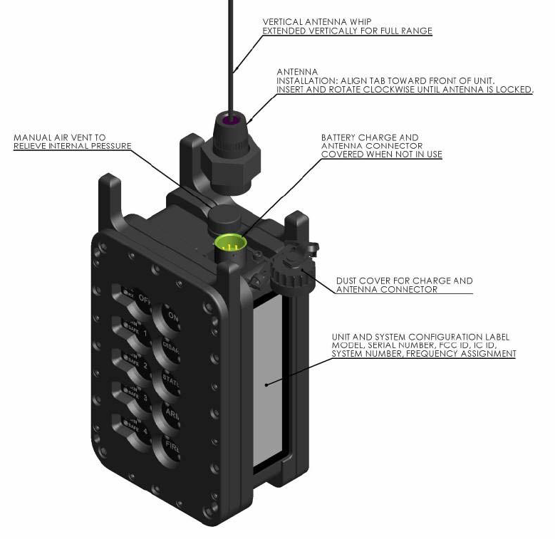
Figure 2-3 Mini Controller Isometric View with Antenna
2.4.13.
2.4.14.
2.4.15.
2.4.16.
Figure 2-3 shows an isometric view to further illustrate the exterior features of
the Mini Controller.
Manual Air Vent: A manual vent is located on top of the unit. The vent is
used to relieve any internal pressure that has accumulated within the unit as a result of
temperature or altitude. The vent is opened when charging to release any gasses or
pressures accumulated during charging. The vent is closed during normal use or when
the unit is exposed to moisture.
Battery Compartment: In the back of the unit is a compartment which stores
the rechargeable battery pack. The battery compartment is isolated from the units
electronics.
System Configuration Label: The System Configuration Label contains
information related to the settings of the unit within the system it operates. The
information displayed on this label may be considered semi-permanent.
1678 RFD OPERATION MANUAL {DRAFT} 12
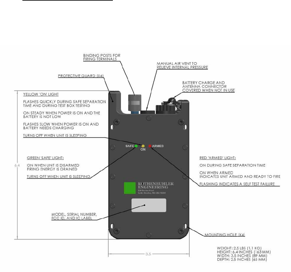
2.5. ELECTRIC REMOTE UNIT
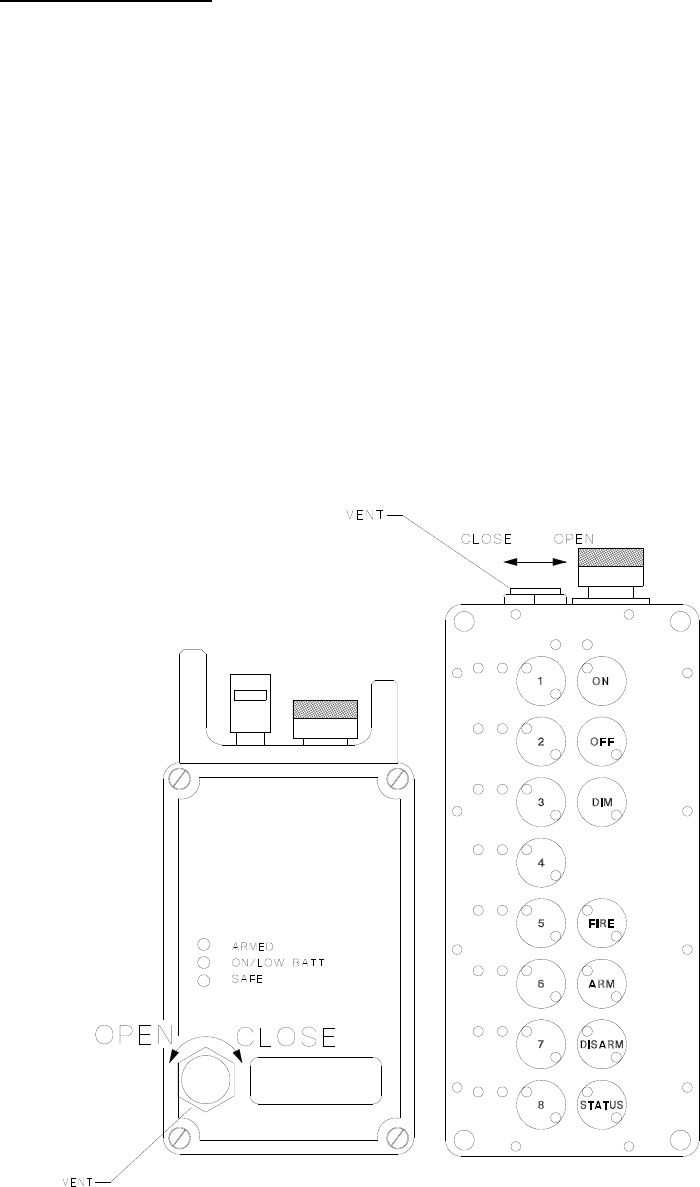
2.5.1. Figure 2-4 shows the external features of the Electric Remote Unit. The unit
is sealed at the manufacturer or service depot and should not be opened during field
activity.
Figure 2-4 Electric Remote Unit
2.5.2. Power ON Self Test: Immediately after the Electric Remote is turned on by
installing the Antenna, a rigorous self-test is performed. If a failure is detected, the red
ARMED light will blink continuously and all other lights will be extinguished. It is not
possible to use the unit once an error has been detected. The unit must be returned to
the Manufacturer for service. Do not attempt to use a failing unit.
1678 RFD OPERATION MANUAL {DRAFT} 13
2.5.3.
2.5.4.
2.5.5.
2.5.6.
2.5.7.
2.5.8.
Safe Separation Time: Upon the installation of the Antenna, a safe
separation countdown timer is initiated. During the safe separation time, the SAFE and
ARMED lights will be on steady, while the ON light blinks rapidly. During the safe
separation time, the unit will not accept any radio commands (i.e. Status, Arm, Disarm,
or Fire). This is to provide a short but highly safe window of time for the user to exit the
immediate vicinity of the blast area. After the safe separation time is complete, the unit
may still be considered safe as long as it does not receive an Arm or a Fire radio
command from the system’s mated Mini Controller. Thus, it is recommended that the
mated Mini Controller be rendered unusable while personnel are within the hazard area.
This can be accomplished by the removal of the Mini Controller’s antenna and its
secure storage until ready for use. The default Safe Separation Time is 15 seconds.
Green SAFE Light: After the Safe Separation Time is complete, the green
SAFE light turns on to indicate that the unit is disarmed; the internal firing capacitor is
fully discharged, and that the unit is operating correctly. The SAFE light will be
extinguished when the unit has entered Sleep Mode (See 2.5.7).
Yellow ON Light: After the unit is activated and has completed its Safe
Separation Time, the yellow ON light will remain illuminated. The ON light will blink
slowly to indicate that its battery needs to be recharged before use. The ON light will be
extinguished when the unit has entered Sleep Mode (See 2.5.7).
Red ARMED Light: After the Safe Separation Time is complete, the red
ARMED light indicates that the unit is armed; the capacitor is charged and the unit is
ready to fire. Appropriate caution of the unit should be observed when the unit is armed.
Sleep Mode: The Electric Remote Unit operates in a sleep mode to extend
the battery’s run time during periods of inactivity. To enter sleep mode, the unit must be
disarmed (safe and capacitor discharged) and the battery must not be low.
Approximately one minute after activity (power on or a radio command), the unit will
enter sleep mode. In sleep mode, the display lights extinguish and all non-essential
functions are suspended. Sleep mode can be exited by sending the unit a radio
command from its mated Mini Controller. Upon receipt of a radio command, the unit will
be immediately awakened and ready for operation. While in sleep mode, units may run
for 200+ hours. Actual sleep mode run time is affected by a variety of factors such as
the sleep mode setting of your system, the state of charge of the battery, the health of
the battery, and the ambient temperatures the unit will be exposed to.
Figure 2-5 provides an angled view of the Electric Remote to show the
System Configuration Label as well as the Battery Compartment Lid. Also illustrated are
various hardware items such as the Binding Posts, Manual Air Vent, and the labels.
1678 RFD OPERATION MANUAL {DRAFT} 14
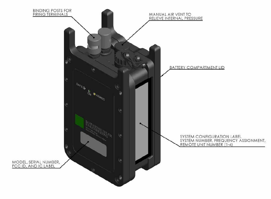
Figure 2-5 Electric Remote Unit Angled View
2.5.9.
2.5.10.
2.5.11.
Binding Posts: The Binding Posts located on top of the Electric Remote Unit
allow the firing cable to attach to the firing terminals. The insulation at the ends of the
firing cable must be removed prior to attachment. One at a time, depress the top of the
binding posts and insert a leg of the firing cable. Release the binding post, causing it to
grab the lead.
Manual Air Vent: A manual vent is located on top of the unit. The vent is
used to relieve any internal pressure that has accumulated within the unit as a result of
temperature or altitude. The vent is opened when charging to release any gasses or
pressures accumulated during charging. The vent is closed during normal use or when
the unit is exposed to moisture.
Battery Compartment: In the back of the unit is a compartment which stores
the rechargeable battery pack. The battery compartment is isolated from the units
electronics.
1678 RFD OPERATION MANUAL {DRAFT} 15
2.5.12.
2.5.13.
System Configuration Label: The System Configuration Label contains
information related to the settings of the unit within the system it operates. The
information displayed on this label may be considered semi-permanent.
Model, Serial Number, FCC ID, and IC Label: The information displayed in
this label is permanently assigned by the factory.
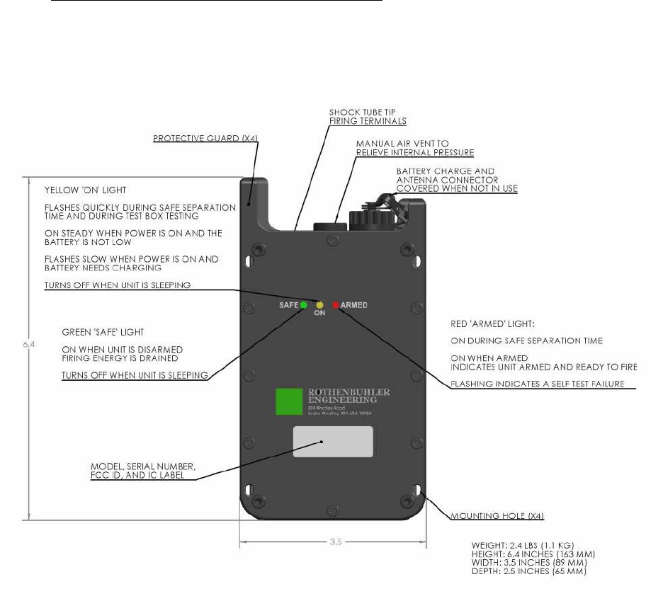
2.6. REMOTE SHOCK TUBE INITIATOR (RSTI)
2.6.1. Figure 2-6 shows the external features of the RSTI. The unit is sealed at the
manufacturer or service depot and should not be opened during field activity.
Figure 2-6 Remote Shock Tube Initiator (RSTI)
2.6.2. The RSTI operates similar to the Electric Remote Unit as described in Section
2.5, but initiates non-electric tubing instead of electric detonators. The RSTI develops
2,500V at the Shock Tube Tip Firing Terminals when firing.
1678 RFD OPERATION MANUAL {DRAFT} 16
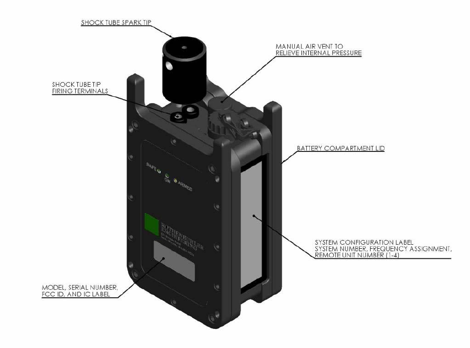
Figure 2-8 Shock Tube Tip
2.6.4. Figure 2-8 shows the installation of the shock tube onto the shock tube firing
tip when preparing for use. Care should be taken when handling the shock tube to
prevent the incursion of debris or moisture into the tube.
• Keep open tube ends capped during storage and transportation.
• Keep the tip needle clean and dry.
• Replace the tip every 200 shots or if misfiring occurs.
WARNING Do not touch the Shock Tube Tip Firing Terminals on the Remote
Shock Tube Initiator (RSTI) when armed or firing. Lethal voltages may be present.
1. Make a fresh cut with a sharp knife removing the last 6 inches of shock tube.
2. Insert the shock tube through the guide hole on the tip as shown in Figure 2-8.
The guide hole secures the tube to the tip and prevents pulling out.
3. Insert the tube into the center hole on the flat side. Feed the tube through the
hole observing the side view hole. The tube should slide onto the igniter needle
until the needle is no longer visible and the tube is resting against the plastic tip
housing.
1678 RFD OPERATION MANUAL {DRAFT} 18
2.7. 3 POSITION BATTERY CHARGER
2.7.1. Figure 2-9 shows the 3 Position Charger that is used in some of the 1678
RFD Kits. The 3 Position Charger provides a basic 3 to 4 hour recharge for up to three
RFD units (e.g. one Mini Controller and two Remotes). It may be stored and used within
the 1678 case/foam, or it can be stored and used as a stand-alone device. The unit is
sealed at the manufacturer or repair depot and should not be opened during field
activity. The 3 Position Charger comes with an AC adapter that can be configured for
use internationally.
Figure 2-9 3 POSITION CHARGER
2.8. TEST BOX
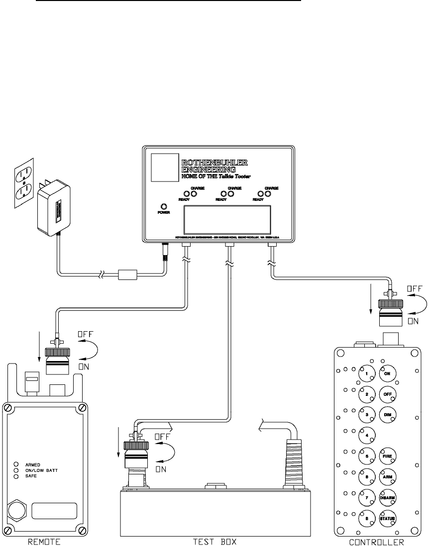
2.8.1. Figure 2-10 provides a drawing of the Test Box. The Test Box is used to
display information from and to evaluate the performance of the Mini Controller and
Electric Remote Units and RSTIs. The Test Box can also be used to change settings
and parameters of the units with certain restrictions.
1678 RFD OPERATION MANUAL {DRAFT} 19
2.8.2. Serial Communications Port: The Test Box can be connected to a serial
RS-232 port on a host PC. The connection can be used to log the results of the tests
performed. The serial communications port is also used when performing parameter
changes.
Figure 2-10 Test Box
2.8.3.
2.8.4.
Test Probe: The Test Probe connects to the antenna/charge connector on
the top of the Mini Controller, Electric Remote, or RSTI. Through the Test Probe, the
Test Box communicates with the test unit to read the various settings, parameters, and
to measure firing circuit and loaded battery voltages.
LCD Display: The LCD displays information both from the Test Box itself
during its power on sequence, and while reading and testing a Mini Controller, Electric
Remote, or RSTI. The LCD’s backlighting will turn on while the unit is active. The
information that may be displayed on the LCD is listed below:
• Serial Number
• Date of Manufacture
• System Number
• Unit ID
• Frequency Assignments
• Firmware Checksum and Version
1678 RFD OPERATION MANUAL {DRAFT} 20

• Battery Temperature and Charge Cycle Count
• Fire Count
• Battery voltage of unit under test while the battery is being loaded down.
• Electric Remote Units and RSTIs under test are armed and fired. The firing
voltages are displayed.
2.8.5.
2.8.6.
Power Input Jack: The Test Box is powered from +12VDC from an AC
adapter. The AC adapter is capable of international use.
Serial Identification Label: This label provides information such as the
Model Number, Serial Number, System Number, Assigned Frequency, and certification
numbers.
2.9. ANTENNA ASSEMBLY
2.9.1. Figure 2-11 provides the physical size, technical requirements and view of the
Antenna Assembly. The power to the Mini Controller Unit and Remote Unit is
interrupted when the Antenna Assembly is not connected.
1678 RFD OPERATION MANUAL {DRAFT} 21
Figure 2-11 Antenna Assembly
2.10. CARRYING CASE
1678 RFD OPERATION MANUAL {DRAFT} 22
2.10.1. Figure 2-12 Carrying Case shows the full system Carrying Case and Figure
2-13 Carrying Case (Half Case)shows the Carrying Case (Half-Case). Shown are the
physical sizes of the Carrying Cases and a view of the storage location for System
assemblies in the Carrying Cases. The Carrying Cases have a pressure equalization
vent near the handle. The vent operation is automatic.
Figure 2-12 Carrying Case
1678 RFD OPERATION MANUAL {DRAFT} 23
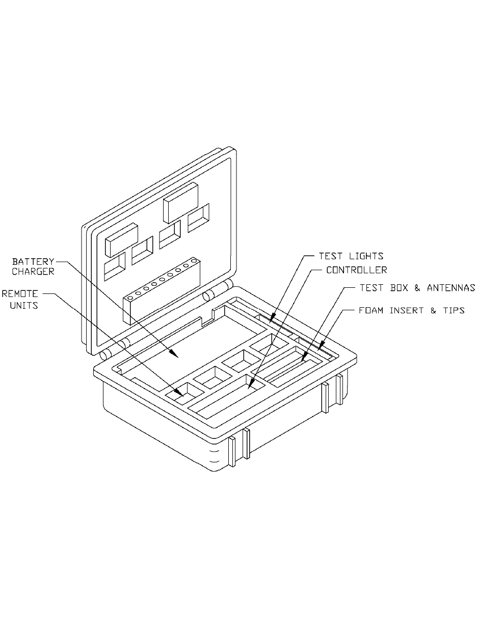
Figure 2-13 Carrying Case (Half Case)
1678 RFD OPERATION MANUAL {DRAFT} 24
2.11. VENT OPERATION
2.11.1. In Figure 2-14, the unit vents shown are manually operated and relieve
internal pressure due to heat and altitude. When the vent is closed, it will not leak in
100 feet of water (30 meters) or up to 30,000 feet (9,100 meters) in altitude.
CAUTION Unequal air pressure inside the Mini Controller Unit may affect the
operation of membrane switch keypad. Extreme pressure differentials may irreversibly
damage the keypad and/or cases.
CAUTION Vents in all units should be momentarily opened and closed immediately
before use.
CAUTION Do not open a vent if there is water on or near the vent. Keep the vents
closed when the relative humidity is above 90%. Take necessary precautions to ensure
moisture does not enter the unit case.
Figure 2-14 Vent Operation
1678 RFD OPERATION MANUAL {DRAFT} 25
2.12. ANTENNA / BATTERY CHARGER CONNECTOR
2.12.1.
2.12.2.
Figure 2-15 shows the connections when using the 3-Position Charger.
The chargers do not discriminate between Mini Controller units and Remote
units; any unit may be connected to any charge connector.
Figure 2-15 3-Position Charger Connection
1678 RFD OPERATION MANUAL {DRAFT} 26
2.13. CONNECTOR DUST COVER OPERATION
2.13.1. In Figure 2-16, the Mini Controller Unit and Remote Unit have an antenna /
battery charger connector dust cover that protects the connector pins from shorting out
and damage when the Antenna Assembly or Battery Charger Assembly is not
connected. The connector dust cover should be connected to the connector when the
connector is not in use.
Figure 2-16 Connector Dust Cover Operation
1678 RFD OPERATION MANUAL {DRAFT} 27

3. SYSTEM SPECIFICATIONS
3.1. RADIO
CARRIER
FREQUENCY
150 - 174 MHz OPERATING
TEMPERATURE
RANGE
-30ºC to 60ºC
-22ºF to 140ºF
-26ºC to 60ºC (RSTI)
-15ºF to 140ºF (RSTI)
FCC Certified <freq. diff. 800 HZ (±400)
MINI CONTROLLER
UNIT & TEST BOX
ELECTRIC
REMOTE & RSTI
FREQUENCY
STABILITY
±2.5PPM OR
(0.000025%)
FREQUENCY
STABILITY
±2.5PPM OR
(0.000025%)
MODULATION 11K2F3D (AFSK) MODULATION 11K2F3D (AFSK)
TRANSMIT
POWER
2-5 Watts (Mini
Controller)
1 Watt (Test Box)
TRANSMIT
POWER
2 Watts (Electric
Remote)
2-5 Watts (RSTI)
OPERATING
POWER
7.2 VDC OPERATING
POWER
7.2 VDC
TRANSMISSION
RANGE (LOS)
5-12 Miles*
3 feet (Test Box)
TRANSMISSION
RANGE (LOS)
1-12 miles*
RECEIVER
SENSITIVITY
12 dB Sinad at
0.28uV
RECEIVER
SENSITIVITY
12 dB Sinad at
0.28uV
(*) Range is specified as line-of sight. The typical transmission range is based on
transmitter power, antenna gain, frequency used, local geography, and local radio
interference.
1678 RFD OPERATION MANUAL {DRAFT} 28

3.2. PHYSICAL
Mini Controller Unit Electric Remote
Unit and RSTI
SIZE (w/out
antenna) (in)
8H x 3W x 2.5D SIZE (w/out
antenna)(in)
6H x 3W x 2.5D
SIZE (w/out
antenna) (cm)
20.32H x 7.62W x
6.35D
SIZE (w/out
antenna)(cm)
15.24H x 7.62W x
6.35D
WEIGHT
(w/battery)
2.5 lbs., 1.14 kg WEIGHT
(w/battery)
2 lbs., 0.91 kg
CASE Die cast aluminum CASE Die cast aluminum
COLOR Black COLOR Black
3.3. BATTERY
Mini Controller Unit Electric Remote
Unit and RSTI
BATTERY PACK Rechargeable
NiMH
BATTERY PACK Rechargeable NiMH
BATTERY LIFE 6 Hours BATTERY LIFE Adjustable between
100-300 Hours
Typical User Setting
is 200 hours*
BATTERY
RECHARGE
240 Min BATTERY
RECHARGE
240 Minutes
STANDBY
CURRENT
110 milliamps STANDBY
CURRENT
80 milliamps
TRANSMIT
CURRENT
2.5 Amp TRANSMIT
CURRENT
1-2.5 Amp
(*) At the end of the 200 hours, the Electric Remote Unit can detonate 13 (2-Ohm)
blasting caps connected in series and attached to 100 feet (30 meters) of 18AWG firing
cable.
1678 RFD OPERATION MANUAL {DRAFT} 29

3.4. TIMING
Mini Controller Unit ARM time: 1/2 ± 0.1 Seconds
Electric Remote Unit ARM time: 7 ± 0.5 Seconds
RSTI Unit ARM time: 4 ± 0.5 Seconds
Mini Controller Unit Arm Time
Period:
1 – 60 Minutes (20 Minute Default) **
Remote Unit Arm Tim Period: 1 – 60 Minutes (20 Minute Default) **
Mini Controller Unit DISARM time: 3 ± 0.1 Seconds
Remote Unit DISARM time: 3 ± 0.1 Seconds
Mini Controller Unit FIRE time: 1 ± 0.1 Seconds
Remote Unit FIRE time:* 20 Milliseconds
*This is the delay after the Remote Unit receives the command signal from the Mini
Controller Unit to Fire.
**The system’s Arm Time Period is factory set. Consult Rothenbuhler Engineering for
details.
3.5. DETONATE OUTPUT
The Remote Unit detonation output pulse is from a 2200 microfarad capacitor charged
to 50 volts.
Stored Energy Level: 2.8 Joule (typical), 1.8 Joule (minimum)
Pulse Voltage Level: 50 VDC (typical), 45 VDC (minimum)
Maximum Firing Resistance:* 28Ω
*This includes firing cables, detonators, & detonator leg wires.
The Remote Shock Tube Initiator (RSTI)’s output pulse is from a 0.15 microfarad
capacitor charged to 2,500 volts.
Stored Energy Level: 0.470 Joule (typical), 0.350 Joule (minimum)
1678 RFD OPERATION MANUAL {DRAFT} 30
Pulse Voltage Level: 2,500 VDC (typical), 2,250 VDC (minimum)
3.6. SYSTEM IDENTIFICATION
3.6.1. Each Mini Controller Unit and Remote Unit is marked with an identification
label. Figure 3-1 shows how the Mini Controller Unit identification label should be
interpreted. Figure 3-2 shows the Remote Unit identification label. The Mini Controller
Unit will only communicate with Remote Units from the same system.
00001
00107 System Number
Figure 3-1 Mini Controller Unit Identification Label
S/N: 1669-20-S00001
Address: 12345
Frequency: 151.505
System #: 0001 R#: 1
FCC ID: CW21669-20
IC: 2758A-166920
System Number
Figure 3-2 Remote Unit Front Identification Label
1678 RFD OPERATION MANUAL {DRAFT} 31

4. PRE-OPERATIONAL PROCEDURES
4.1. PHYSICAL INSPECTION
CAUTI
s
onnector on the Mini Controller Unit
ve the antenna / battery charger connector dust cover and ensure the
electrical pin area is clean and free of foreign material. Replace the dust cover.
mbly whip is not broken and that the whip has not
separated from the sealing compound at the top of the connector.
its are
not damaged.
s are clean and not
damaged.
ove the yellow dust cover from the Antenna Assembly and ensure that
there is no foreign material in the electrical contact area. Replace the yellow dust cover.
TERY CHARGING WITH THE 3-POSITION CHARGER
ON Inspect all components for physical damage.Do not use any
component that is damaged, suspected of being damaged, or is not able to operate a
designed. The safety of the operation could be compromised.
4.1.1. Ensure the antenna / battery charger c
and Remote Unit is not damaged.
4.1.2. Remo
4.1.3. Ensure the Antenna Asse
4.1.4. Ensure that the spring-loaded binding posts on the Electric Remote Un
4.1.5. Ensure the Shock Tube Tip Jacks on the top of the RSTI
4.1.6. Rem
4.2. BAT
antenna / battery charger connector on each unit.
4.2.2. For each new battery charge cycle, the charger increments a charge cycle
co ed
nt
rmance.
4.2.3.
ons. Each charge station
has a CHARGE and a SLOW light. The 3-Position Charger has a single POWER light.
The 3-Position Charger does not have a discharge function. Two 3-Position Chargers
can be employed to charge all 6 units of the Half Case kit during one charge session.
4.2.1. The battery packs in the Mini Controller Unit, Remote Unit and Test Box
contain rechargeable NiMH batteries. The battery packs are recharged through the
unter stored within the packs of each unit. The charge cycle count can be display
using the Test Box. Battery pack replacement is recommended when the charge cou
reaches 300 charge cycles to ensure reliable perfo
The battery pack in the Mini Controller Unit, Remote Units and Test Box
should be charged before the system is used each time. The 3-Position Charger will
charge the Mini Controller Unit, Remote Units and the Test Box in 240 minutes typically.
Each 3-Position Charger has three independent charge stati
1678 RFD OPERATION MANUAL {DRAFT} 32
4.2.4. n
VDC @ 2.5A which can also be supplied by an optional 12V auto accessory adapter.
the side
CAUTION Do not open a vent if there is water on or near the vent. Keep the vents
clo nsure
4.2.7. Open the vent on each unit to be charged.
the 3-Position Charger. The charger does
between Mini Controller units, Remote units and Test Boxes; any unit
onnected unit will flash for approximately 5
seconds. The flashing CHARGE light indicates that charging is pending.
4.2.10. In normal operation, the CHARGE light will be on steady (non-blinking) after 5
se
4.2.11. The battery must be within the temperature range 32 ºF and 104 ºF (0 to +40
ºC
4.2.12. If the detected battery voltage is less than 6 volts, the battery will be slow
ch
ithin the battery, the green SLOW light will blink continuously.
4.2.13.
off.
4.2.14.
4.2.15. If a unit is left turned on beyond the low battery point, the battery pack may
no
The 3-Position Charger does not feature a discharge function. To conditio
the batteries of the units, they should periodically be left on until the low battery
condition occurs before recharging. A full discharge will help to rejuvenate batteries that
have been stored for extended periods or that may have developed a memory.
4.2.5. Plug the supplied AC Power Adapter into an AC outlet. The AC Power
Adapter will operate from 100-240VAC, 50-60 Hz. The charger itself requires 11-14
4.2.6. Insert the DC plug from the AC Power Adapter into the power jack on
of the charger. The POWER light will turn on.
sed when the relative humidity is above 90%. Take necessary precautions to e
moisture does not enter the unit case.
4.2.8. Connect each unit to be charged to
not discriminate
may be connected to any of the 3 charge connectors.
4.2.9. The CHARGE light for each c
conds has passed. The steady CHARGE light indicates that the battery is being
charged.
) for fast charging to occur.
arged until the voltage is high enough for rapid charge. If the battery pack is
defective and the voltage does not rise to the correct level, or if an internal error is
detected w
When rapid charging terminates, the green SLOW light will be on steady, and
the CHARGE light will be turned
Rapid charging terminates when the charger detects the battery pack is
charged. Rapid charging will also terminate after 4 hours, or if the battery pack’s
temperature is out of range.
t fully charge before the 4 hour rapid charge time limit expires. In that case, charge
the battery pack again.
1678 RFD OPERATION MANUAL {DRAFT} 33

4.2.16.
E SYSTEM
Close the vent on each Remote Unit and the Mini Controller Unit
4.3. BENCH TESTING TH
WARNING Radio frequency energy of sufficient magnitude can cause blasting
caps to detonate.
4.3.1. The System test must be conducted in an area that is at least 100 feet (30
me other
explosives.
4.3.2. All RFD System controls are described in detail in section 2.
of
troller Unit. Ensure the Mini Controller Unit is off.
4.3.4. er connectors of
ts. The ON/LOW BATT and SAFE lights will come on steady. If the
e with section 4.1.6.
4.3.5.
will turn on steady. If
the yellow light does not turn on steady, but flashes, this indicates a low battery for the
Mi
imately 5 seconds. During that time the Mini
Controller Unit is requesting status from the Remote Units.
A flashing
DISARMED light indicates the Mini Controller Unit did not receive the Remote Unit’s
sta
ters) from the nearest blasting caps, wires connected to blasting caps, or
CAUTION All units must be thoroughly tested and the batteries fully charged prior
to operational use.
4.3.3. Install the Antenna Assembly on the antenna / battery charger connector
the Mini Con
Install the Antenna Assemblies on the antenna / battery charg
the Remote Uni
ON/LOW BATT light is flashing, the Remote Unit has a low battery. Recharge the
battery in accordanc
Turn the Mini Controller Unit on by pressing the “ON” switch for 1 second. A
yellow light located in the upper left quadrant of the “ON” switch
ni Controller Unit. Recharge the battery in accordance with section 4.1.6.
4.3.6. Press the “STATUS” switch for 1 second. The red TX light on the Mini
Controller Unit will start blinking for approx
4.3.7. When the TX light stops flashing, the green DISARMED light will come on
steady adjacent to the switches numbered “1” through “4”. A steady DISARMED light
indicates that Remote Unit answered back with its status and it is disarmed.
tus transmission.
WARNING Ensure that blasting caps are not connected to any of the Remote
Units during bench testing.
4.3.8. Select all of the Remote Units by pressing switches “1” through “4”. A yellow
light will be lit in each switch to indicate the corresponding Remote Unit is selected.
1678 RFD OPERATION MANUAL {DRAFT} 34
4.3.9. Press the “ARM” switch for ½ second. The red ARMED light for each
selected Remote Unit will flash on the Mini Controller Unit display panel for
approximately 5 seconds and then come on steady. The ARMED light for each
se
4.3.10. e
hts at the
the
4.3.11. Re-Arm the Remote Units. Before the Arm Time Period expires, press the
“D t will
4.3.12.
e
RMED to
DISARMED. Proceed to 4.3.14.
that
ntroller
DISARMED.
Note: t
e RSTI and the Shock Tube Igniter Tip
hots on your tip before replacement. If
4.3.14. Turn off the Mini Controller Unit by pressing the “OFF” switch. Turn off the
lected Remote Unit will grow brighter and then stay on steady. The Remote Units are
now armed.
Observe the Mini Controller Unit and Remote Units. After the Arm Tim
Period expires, the Remote Units will automatically disarm. The ARMED lig
Mini Controller Unit and Remote Units should turn off. The DISARMED lights at
Mini Controller Unit and SAFE lights at the Remote Units should turn on.
ISARM” switch on the Mini Controller Unit. The Mini Controller Unit's ARMED ligh
be turned off. The DISARMED lights at the Mini Controller Unit should blink for
approximately 3 seconds and then turn on steady. The ARMED lights at the Remote
Units will turn off and the Remote Units’ SAFE lights will turn on.
If firing RSTI Units, proceed to 4.3.13. Connect a test bulb assembly to the
binding posts of each Electric Remote Unit. Arm the Electric Remote Units. Press the
“FIRE” switch on the Mini Controller Unit. The test bulb should flash brightly. Th
ARMED light will turn off and the SAFE light will turn on at each Electric Remote Unit.
The displayed status at the Mini Controller Unit will change from A
4.3.13. Install the firing tip into the Shock Tube Tip Jacks on the top of each RSTI.
Arm the RSTI Units. Press the “FIRE” switch on the Mini Controller Unit. Observe
bright sparks should be heard and seen on each unit. The ARMED light will turn off and
the SAFE light will turn on at each RSTI. The displayed status at the Mini Co
Unit will change from ARMED to
When firing the RSTI with no tip or with a faulty tip, the green DISARMED ligh
for that unit may not initially turn on following a FIRE operation. A subsequent press of
the “STATUS” switch illuminates the green DISARMED light.
Note: Refer to Section 2.6 for details about th
handling and replacement. Never exceed 200 s
you notice the spark is weak or if misfires occur, the tip needs replacement. Always
keep a spare tip as a backup. Keep the tip needle clean and dry.
Remote Units by removing their Antenna Assemblies.
4.3.15. The RFD system is now ready to use operationally.
1678 RFD OPERATION MANUAL {DRAFT} 35

5. OPERATIONAL PROCEDURES
WARNING WARNING Use of this system and its components must be
restricted to personnel qualified and experienced in the field of explosives and
detonating devices. Under no circumstances shall untrained personnel attempt to use
this manual as a text for self-teaching.
WARNING Employ standard blasting system safety standards when using this
equipment with explosives.
WARNING All units must be thoroughly tested and the batteries fully charged prior
to operational use.
5.1. READY THE SYSTEM AT SITE
5.1.1. Remote Units. Select the number of Electric Remote Units or RSTIs required
for the operation. Remove the dust cover from the antenna / battery charger connector.
Install the Antenna Assembly on to the antenna / battery charger connector. This will
turn on the Remote Unit. The yellow ON/LOW BATT light and green SAFE light will be
turned on. The green SAFE light will be on for the first minute, whenever the Remote
Unit is turned on and it is disarmed. In the disarmed state, the firing capacitor charge
circuit is disabled, the firing terminals are electrically isolated from the firing capacitor,
and the firing terminals are shunted to each other. If the yellow ON/LOW BATT light is
flashing, the Remote Unit battery is low and should be recharged before use.
5.1.2. Remote Sleep Mode. After 1 minute, the display lights on the Remote Units
will extinguish. During this time, the Remote unit is in a low power ‘sleep’ state to
conserve battery power. Sleep Mode can only be entered if the Remote Unit is
disarmed. The Remote units are quickly awakened by the Mini Controller’s radio signal
when needed for use.
WARNING Do not connect a blasting cap to a Remote Unit unless the green
SAFE light is on, the red ARMED light is off, and the yellow ON/LOW BATT light is on
steady. This indicates there is no voltage on the binding posts, the binding posts are
electically isolated from the firing capacitor, the binding posts are shunted to each other,
and the battery is not low.
5.1.3. Open and close the vent on each Remote Unit and the Mini Controller Unit to
equalize the case pressure. Unscrew the vent, one revolution, to open.
5.1.4. Remove the dust cover from the antenna / battery charger connector of the
Mini Controller Unit. Install the Antenna Assembly on to the antenna / battery charger
connector. This will enable the keypad on the Mini Controller Unit.
1678 RFD OPERATION MANUAL {DRAFT} 36

WARNING Do not use the Mini Controller Unit within 100 feet (30 meters) of
explosives, blasting caps, or wires leading to them. Th
which can cause detonation of caps if within 100 feet. The 5 watt Mini Controller
e Mini Controller signal is 5 watts,
drant of the “ON” switch will turn on steady. If
does not turn on steady, but flashes, this indicates a low battery for the
the Mini Controller Unit. The red TX light will
green DISARMED light corresponding to each
Re
to shoot.
complies with the Recommended Table of Distances established by the Institute for the
Makers of Explosives (IME) when placed beyond 100 feet of explosives.
5.1.5. Turn the Mini Controller Unit on by pressing the “ON” switch for 1 second. A
yellow light located in the upper left qua
the yellow light
Mini Controller Unit. Recharge the battery in accordance with section 4.1.6.
5.1.6. Adjust the intensity of the LED display on the Mini Controller for the desired
setting by repressing the ‘ON’ switch on the Mini Controller.
5.1.7. Press the “STATUS” switch on
flash for approximately 5 seconds. The
mote Unit will come on steady if the Mini Controller Unit receives a status message
from that Remote Unit. If the Mini Controller Unit does not receive a status message
from a Remote Unit, the green DISARMED light for that Remote Unit will flash on the
Mini Controller Unit display panel.
Note: The Mini Controller Unit battery life is approximately 6 hours when in the “ON”
condition. To conserve battery life, the Mini Controller Unit should be turned off when
not being used.
5.1.8. Turn the Mini Controller Unit “OFF” until Remote Units are in place and wired
5.2. PLACEMENT OF REMOTE UNITS
WARNING Do not connect a blasting cap to a Remote Unit unless the green
SAFE light is on, the red ARMED light is off, and the yellow ON/LOW BATT light is on
e
r,
and free from
obstruction within 100 feet (30 meters) of the shot. Use sandbags or other suitable
ma
reen light on
steady).
steady. This indicates there is no voltage on the binding posts, the binding posts ar
electically isolated from the firing capacitor, the binding posts are shunted to each othe
and the battery is not low.
5.2.1. The range of the RFD is typically Error! Reference source not found.
under most conditions.
5.2.2. Place the Remote Units with the antenna in a vertical position
terials to protect the Remote Units from the shot.
5.2.3. Ensure that all Remote Units indicate a SAFE condition (g
1678 RFD OPERATION MANUAL {DRAFT} 37

5.2.4. If using the RSTI, proceed to Section 5.2.7. After performing standard
demolition circuit checks and before placing initiator into the main charge, depress the
two spring-loaded binding posts on the Electric Remote Unit.
5.2.5. Insert one leg of the demolition wire in each binding post and allow the
binding posts to close on the wire ends.
5.2.7. Install the non-electric shock tubing onto the Shock Tube Tip and mount the
tip
.
5.2.8.
f
cated more Error! Reference source not found.
than from the Mini Controller Unit, refer to section 5.3.11.
i Controller Unit, and other Remote Units are more than Error!
Reference source not found. from the Mini Controller Unit, refer to section 5.4.11.
STEM OPERATION – REMOTE UNITS WITHIN ERROR! REFERENCE
5.2.6. Ensure the wire is held securely by the binding posts and that the wire ends
are not touching the Electric Remote’s case or each other. Proceed to Section 5.2.8.
onto the RSTI according to Section 2.6. Take care to ensure no moisture or debris
enter the shock tube or contact the Shock Tube Tip’s needle
Prepare the shot and return to the safe firing area.
5.2.9. If all Remote Units are located within Error! Reference source not found. o
the Mini Controller Unit, refer to section 5.2.11.
5.2.10. If all Remote Units are lo
5.2.11. If some Remote Units are located within Error! Reference source not
found. of the Min
5.3. SY
SOURCE NOT FOUND. OF MINI CONTROLLER UNIT
Note: If the distance between the Mini Controller Unit and the Remote Units is in
ions
he
erence source not found. of the Remote Units. The only
difference is the method the status indication Unit
nits
ntroller Unit display panel to indicate the Mini Controller Unit did
not receive a status message from the Remote Unit. Once the Remote Units are set up
for
excess of Error! Reference source not found., the Remote Units status transmiss
may not be received by the Mini Controller Unit. The Mini Controller Unit will command
the Remotes from a distance greater than Error! Reference source not found., but t
Remote Status may not be confirmed. The Mini Controller Unit performs just as it would
when it is within Error! Ref
s are displayed on the Mini Controller
display panel. The ARMED and DISARMED status lights for out of range Remote U
will flash on the Mini Co
the shot, the operator must assume the Remote Units have received the command.
5.3.1. Ensure the area is clear.
5.3.2. Turn the Mini Controller Unit on.
1678 RFD OPERATION MANUAL {DRAFT} 38
5.3.3. s from
come on steady for the
Remote Units that the Mini Controller Unit receives a disarmed status message from.
re to be used in the shot by pressing the
corresponding numbered switches “1” through “4”. Press the numbered switches one at
a time.
System Safety Feature Once armed, the Remote Units must be sent a Fire
co
will remain isolated from
the firing capacitor and the binding posts will remain shunted together.
5.3.5. To arm the selected Remote Units, press the “ARM” switch. The red ARMED
lig
Units are now ARMED!
5.3.6. e
MED light will go out and the
green DISARMED light for each selected Remote Unit will come on steady on the Mini
Co
ht
for that unit may not initially turn on following a FIRE operation. A subsequent press of
5.3.7. If not all the Remote Units were selected for the shot, repeat above steps to
Remote Unit is approached. Maintain a safe distance from the Remote Unit. Do not
approach the Remote Unit until DISARMED status is confirmed with a steady
DISARMED light for that Remote Unit on the Mini Controller Unit display panel. Under
no conditions should the “FIRE” switch be pressed as the Remote Unit is approached.
DO NOT bring the Mini Controller Unit closer than 100 feet (30 meters) to blasting caps,
wires connected to blasting caps, or other explosives.
Press the “STATUS” switch. The Mini Controller Unit will request statu
all Remote Units. The red TX light will flash for approximately 5 seconds. The green
DISARMED light on the Mini Controller Unit display panel will
5.3.4. Select the Remote Units that a
mmand within the Arm Time Period. If the Remote Units do not receive a Fire
command within the Arm Time Period, they will automatically disarm. The firing
capacitor will be safely internally discharged, the binding posts
ht next to each selected Remote Unit switch will flash for approximately 5 seconds
and then come on steady. The selected Remote
To fire the Remote Units, press the “FIRE” switch and hold for 1 second. Th
operator should get an indication of shot initiation. The AR
ntroller Unit display panel.
Note: When firing the RSTI with no tip or with a faulty tip, the green DISARMED lig
the “STATUS” switch illuminates the green DISARMED light.
initiate the remaining shots.
5.3.8. To disarm any Remote Units that have been armed, select the Remote Units
and press the “DISARM” switch. All selected Remote Units will return to the
DISARMED mode in approximately 3 seconds.
CAUTION Do not assume the Disarm command has been received by the
Remote Unit unless DISARMED status is confirmed with a steady DISARMED light for
that Remote Unit on the Mini Controller Unit display panel. If distance appears to be the
problem, move closer to the Remote Unit following standard procedures for this type of
situation. The “STATUS” and/or “DISARM” switches may be pressed repeatedly as the
1678 RFD OPERATION MANUAL {DRAFT} 39

5.3.9.
5.3.11. Refer to Post Operational Procedures in chapter 5.5.14.
Turn off the Mini Controller Unit.
5.3.10. Recover the fielded Remote Units.
5.4. SYSTEM OPERATION – REMOTE UNITS MORE THAN ERROR! REFERENCE
SOURCE NOT FOUND. FROM MINI CONTROLLER UNIT
ssions
mand
just as it would
when it is within Error! Reference source not found. of the Remote Units. The only
dif
its
roller Unit did
not receive a status message from the Remote Unit. Once the Remote Units are set up
for
5.4.2. Turn the Mini Controller Unit on.
5 seconds. The green
DISARMED light on the Mini Controller Unit display panel will flash for all Remote Units
tha
5.4.4. Select the Remote Units that are to be used in the shot by pressing the
co
ty Feature Once armed, the Remote Units must be sent a Fire
re
D
Note: If the distance between the Mini Controller Unit and the Remote Units is in
excess of Error! Reference source not found., the Remote Units status transmi
may not be received by the Mini Controller Unit. The Mini Controller Unit will com
the Remotes from a distance greater than Error! Reference source not found., but the
Remote status may not be confirmed. The Mini Controller Unit performs
ference is the method the status indications are displayed on the Mini Controller Unit
display panel. The ARMED and DISARMED status lights for out of range Remote Un
will flash on the Mini Controller Unit display panel to indicate the Mini Cont
the shot, the operator must assume the Remote Units have received the command.
5.4.1. Ensure the area is clear.
5.4.3. Press the “STATUS” switch. The Mini Controller Unit will request status from
all Remote Units. The red TX light will flash for approximately
t the Mini Controller Unit does not receive a status message from.
rresponding numbered switches “1” through “4”. Press the numbered switches one at
a time.
System Safe
command within the Arm Timeout Period. If the Remote Units do not receive a Fi
command within the Arm Timeout Period, they will automatically disarm. The firing
capacitor will be safely internally discharged, the binding posts will remain isolated from
the firing capacitor and the binding posts will remain shunted together.
5.4.5. To arm the selected Remote Units, press the “ARM” switch. The red ARME
light next to each selected Remote Unit switch will flash for 5 seconds, then come on
steady for two seconds, and then continue to flash. The selected Remote Units are now
assumed to be ARMED!
1678 RFD OPERATION MANUAL {DRAFT} 40

5.4.6. e “FIRE” switch. The operator should get
an indication of shot initiation. The ARMED light will go out and the green DISARMED
lig n the Mini Controller Unit display panel.
5.4.7. eat above steps to
initiate the remaining shots.
d, select the Remote Units
and press the “DISARM” switch. All selected Remote Units will return to the
wi other explosives.
5.4.9.
5.4.10.
To fire the Remote Units, press th
ht for each selected Remote Unit will flash o
If not all the Remote Units were selected for the shot, rep
5.4.8. To disarm any Remote Units that have been arme
DISARMED mode in approximately 3 seconds.
CAUTION Do not assume the Disarm command has been received by the
Remote Unit unless DISARMED status is confirmed with a steady DISARMED light for
that Remote Unit on the Mini Controller Unit display panel. If distance appears to be the
problem, move closer to the Remote Unit following standard procedures for this type of
situation. The “STATUS” and/or “DISARM” switches may be pressed repeatedly as the
Remote Unit is approached. Maintain a safe distance from the Remote Unit. Do not
approach the Remote Unit until DISARMED status is confirmed with a steady
DISARMED light for that Remote Unit on the Mini Controller Unit display panel. Under
no conditions should the “FIRE” switch be pressed as the Remote Unit is approached.
DO NOT bring the Mini Controller Unit closer than 100 feet (30 meters) to blasting caps,
res connected to blasting caps, or
Turn off the Mini Controller Unit.
Recover the fielded Remote Units.
5.4.11. Refer to Post Operational Procedures in chapter 5.5.14.
5.5. SYSTEM OPERATION – REMOTE UNITS BOTH WITHIN AND IN EXCESS OF
ERROR! REFERENCE SOURCE NOT FOUND. AND LESS THAN ERROR!
REFERENCE SOURCE NOT FOUND. FROM MINI CONTROLLER UNIT
Note: If the distance between the Mini Controller Unit and the Remote Units is in
ssions
nd
the
i Controller Unit
dis
excess of Error! Reference source not found., the Remote Units status transmi
may not be received by the Mini Controller Unit. The Mini Controller Unit will comma
the Remotes from a distance greater than Error! Reference source not found., but
Remote status may not be confirmed. The Mini Controller Unit performs just as it would
when it is within Error! Reference source not found. of the Remote Units. The only
difference is the method the status indications are displayed on the Min
play panel. The ARMED and DISARMED status lights for out of range Remote Units
will flash on the Mini Controller Unit display panel to indicate the Mini Controller Unit did
not receive a status message from the Remote Unit. Once the Remote Units are set up
for the shot, the operator must assume the Remote Units have received the command.
1678 RFD OPERATION MANUAL {DRAFT} 41
5.5.1.
5.5.2.
the Remote Units (ON/LOW BATT, ARMED, and SAFE)
will be displayed with steady lights on the display panel of the Mini Controller Unit.
Unit, the
d their status lights will flash on the
nit display panel to indicate unconfirmed status. Accordingly the
5.5.6. ontroller Unit will request status from
all r approximately 5 seconds. The green
DISARME splay panel will flash for all the Remote
Un e from.
Remote Units are armed.
The RFD will operate in a two-way mode (confirmed communications – range
to Error! Reference source not found.) and one-way mode (unconfirmed
communications – range greater than Error! Reference source not found.).
If the Remotes are within Error! Reference source not found. of the Mini
Controller Unit, the status of
5.5.3. If one or more Remote Units are out of range of the Mini Controller
status of these Remote Units will be assumed an
Mini Controller U
operator must assume the following:
• Commands have been received by the Remote Units.
• The Remote Unit battery is sufficiently charged to activate the firing circuit.
• A DISARM command should not be assumed.
5.5.4. Ensure the area is clear.
5.5.5. Turn the Mini Controller Unit on.
Press the “STATUS” switch. The Mini C
Remote Units. The red TX light will flash fo
D light on the Mini Controller Unit di
its that the Mini Controller Unit does not receive a status messag
5.5.7. Select the Remote Units that are to be used in the shot by pressing the
corresponding numbered switches “1” through “4”. Press the numbered switches one at
a time.
System Safety Feature Once armed, the Remote Units must be sent a Fire
command within the Arm Time Period. If the Remote Units do not receive a Fire
command within the Arm Time Period, they will automatically disarm. The firing
capacitor will be safely internally discharged, the binding posts will remain isolated from
the firing capacitor and the binding posts will remain shunted together.
5.5.8. To arm the selected Remote Units, press the “ARM” switch. The red ARMED
light next to each selected Remote Unit switch will flash for 5 seconds, and then come
on steady for two seconds. ARMED lights for selected Remote Units that the Mini
Controller Unit did not receive a status message from will begin to flash again. The
selected Remote Units are now assumed to be ARMED! For unconfirmed
communications, count to 5 from when the "ARM" switch is pressed and assume the
1678 RFD OPERATION MANUAL {DRAFT} 42
5.5.9.
ISARMED
panel.
5.5.10.
5.5.11. To disarm any Remote Units that have been armed, select Remote Units and
pre
arm command has been received by the Remote
appears to be the
problem, move closer to the Remote Unit following standard procedures for this type of
e
Remote Unit is approached. Maintain a safe distance from the Remote Unit. Do not
irmed with a steady
DISARMED light for that Remote Unit on the Mini Controller Unit display panel. Under
no conditions should the “FIRE” switch be pressed as the Remote Unit is approached.
DO NOT bring the Mini Controller Unit closer than 100 feet (30 meters) to blasting caps,
wi xplosives.
5.5.12.
5.5.14. Refer to Post Operational Procedures in chapter 5.5.14.
To fire the Remote Units, press the “FIRE” switch. The operator should get
an indication of shot initiation. The ARMED light will go out and the green D
light for each selected Remote Unit will flash on the Mini Controller Unit display
If not all the Remote Units were selected for the shot, repeat above steps to
initiate the remaining shots.
ss the “DISARM” switch. All selected Remote Units will return to the DISARMED
mode in approximately 3 seconds.
CAUTION Do not assume the Dis
Unit unless DISARMED status is confirmed with a steady DISARMED light for that
Remote Unit on the Mini Controller Unit display panel. If distance
situation. The “STATUS” and/or “DISARM” switches may be pressed repeatedly as th
approach the Remote Unit until DISARMED status is conf
res connected to blasting caps, or other e
Turn off the Mini Controller Unit.
5.5.13. Recover the fielded Remote Units.
1678 RFD OPERATION MANUAL {DRAFT} 43

6. POST OPERATIONAL PROCEDURES
6.1. SECURING THE SYSTEM
6.1.1. Turn the Mini Controller Unit off and remove the Antenna Assembly. This
action disables the Mini Controller Unit.
plastic cap on the Antenna Assembly.
6.1.2. Replace the dust cover on the antenna / battery charger connector on the
Mini Controller Unit and replace the
6.1.3. Remove the Antenna Assemblies from the Remote Units. This action turns
off the Remote Units.
6.1.4. Replace the dust cover on the antenna / battery charger connector on the
Remote Units and replace the plastic cap on the Antenna Assembly.
6.2. PHYSICAL INSPECTION
6.2.1. Inspect the Mini Controller Unit and Remote Units for physical damage.
6.2.2. Inspect the units for dirt or corrosion around/on connector pins and vent.
6.2.3. amage. Return unit to manufacturer.
6.2.4. .
6.2.5. nt is closed securely
and wash units in warm soapy water.
6.2.6. Rinse units with clean water and dry thoroughly.
6.2.7. Inspect units for damage. Replace as necessary.
6.3. PACKAGING
Replace any unit found to have d
Clean units using a soft bristle brush
If a unit cannot be cleaned by brushing, make sure the ve
6.3.1. Re-package all components in carrying case.
6.4. MAINTENANCE & EQUIPMENT STORAGE
6.4.1. Periodic battery charging
6.4.2. Check for signs of corrosion around and on connector pins.
1678 RFD OPERATION MANUAL {DRAFT} 44

7. BASIC TROUBLESHOOTING IN THE FIELD
7.1. REMOTE UNITS
7.1.1.
.
LER UNIT
ON and SAFE lights do not illuminate when the Antenna Assembly is
installed.
a) Check Antenna Assembly and make sure it is seated, “clicks” on to the connector
b) Recharge the battery.
c) Try a different Antenna Assembly.
7.2. MINI CONTROL
a) Check Antenna Assembly and make sure it is seated, “clicks” on to the connector.
witch for 5 seconds.
7.2.2.
rence source not found. away from the
bly on the Mini Controller Unit.
The antenna is not positioned vertically.
nna is next to another radio antenna.
• Use optional magnetic mount antenna for improved gain. This antenna is
7.3. IATOR
7.2.1. ON Light does not stay on.
b) Press and hold the “ON” s
c) Mini Controller Unit battery needs to be recharged.
Command receipt is not confirmed by Remote Unit.
a) Remote Unit is more than Error! Reference source not found. from Mini Controller
Unit.
b) If the Remote Unit is less than Error! Refe
Mini Controller Unit.
Check for damage to Mini Controller Unit Antenna Assembly.
Try a different Antenna Assem
Move at least 25 feet in any direction and try again.
Reposition the Remote Unit if:
•
• The ante
• The antenna is surrounded by metallic objects.
available by special order only.
REMOTE SHOCK TUBE INIT
7.3.1.
a) The Shock Tube Tip may be worn or damaged. Replace tip.
Unit will not ignite the shock tube.
1678 RFD OPERATION MANUAL {DRAFT} 45
b) The shock tube may be damaged from moisture. Try a fresh cut or replace the
needle and tubing. Ensure the tube covers the entire needle. Ensure both the
the shock tube lead-in is dry when mating.
1678 RFD OPERATION MANUAL {DRAFT} 46

8. O
8.1.1. When power lines are in the area, the radio transmission distance is reduced.
The system can operate at the following distance, when the Mini Controller Unit is
elevated to a maximum transmission location angle to the Remote Unit location (see
Figure 8-1).
Over
PTIMIZING RANGE
Minimum Distance
Open Land or Water with Power Lines Error! Reference source not
found.
Dense Vegetation without Power Lines Error! Reference source not
found.
Open Land or Water without Power Lines Greater than 5 Miles
1678 RFD OPERATION MANUAL {DRAFT} 47
Figure 8-1 Unit Normal Transmission Location
8.1.2. If the Mini Controller Unit and Remote Unit must be placed in a position other
than location in Figure 8-1, use Figure 8-2 or Figure 8-3. The minimum transmission
will occur when the Mini Controller Unit antenna and the Remote Unit antenna are
placed in the line of site. The maximum transmission occurs when the line of site lays in
a path of 5 to 25 degrees above unit top plane perpendicular to the antenna. Both the
Mini Controller Unit antenna and the Remote Unit antenna have the same radiant
energy pattern as shown in Figure 8-4.
1678 RFD OPERATION MANUAL {DRAFT} 48
Figure 8-2 Remote Unit Elevated
1678 RFD OPERATION MANUAL {DRAFT} 49
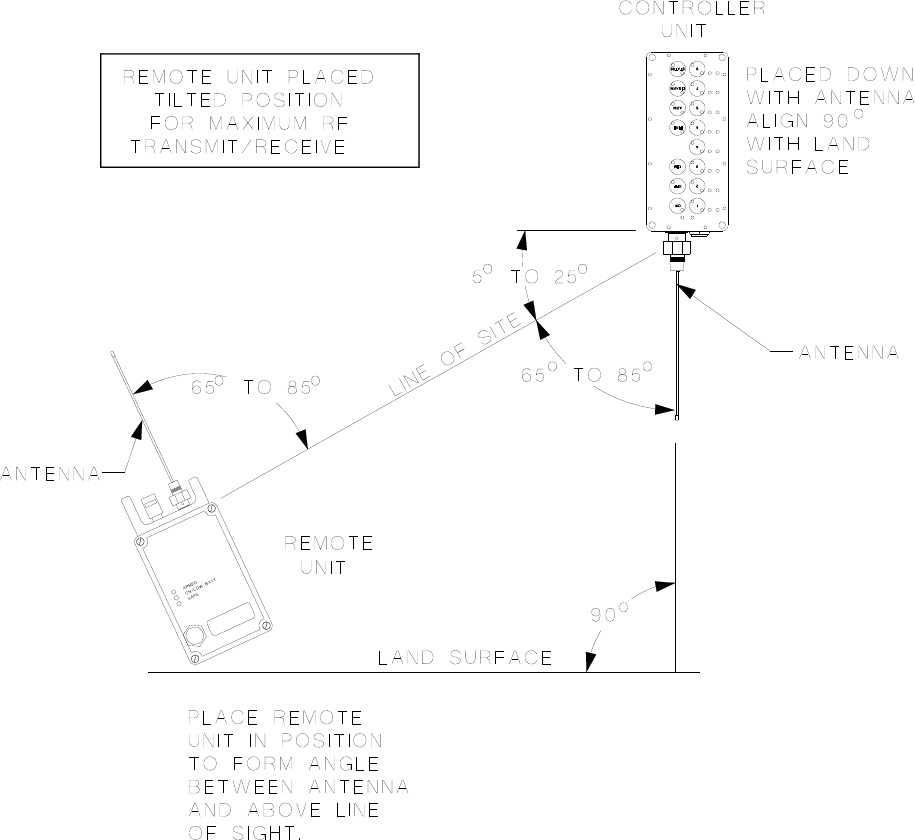
Figure 8-3 Mini Controller Unit Elevated
1678 RFD OPERATION MANUAL {DRAFT} 50
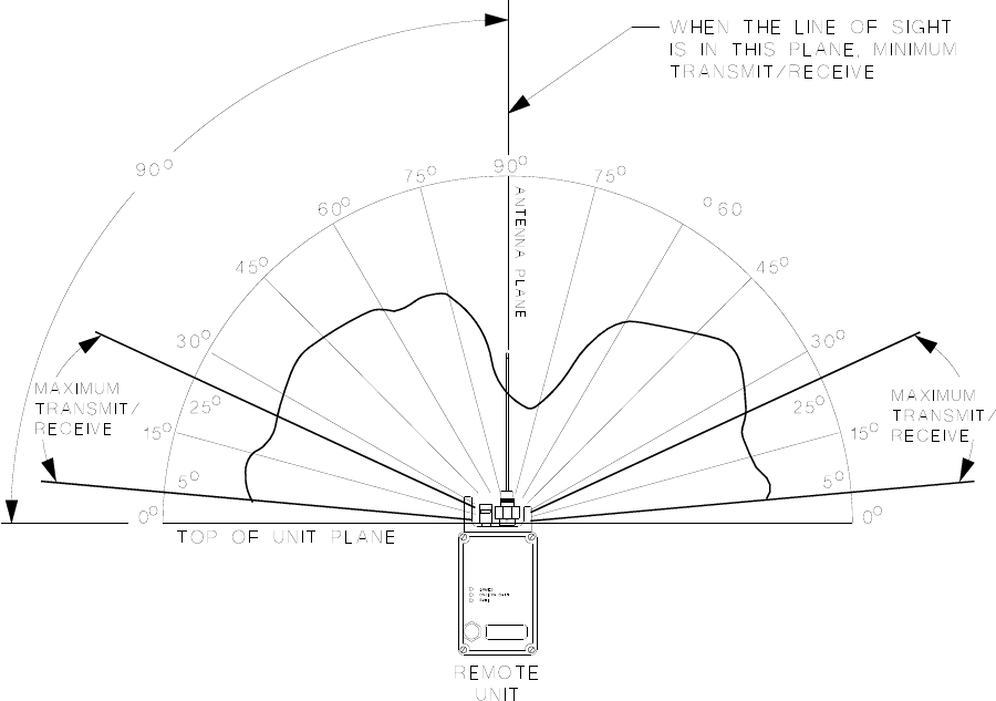
Figure 8-4 Antenna Radiation Pattern
1678 RFD OPERATION MANUAL {DRAFT} 51
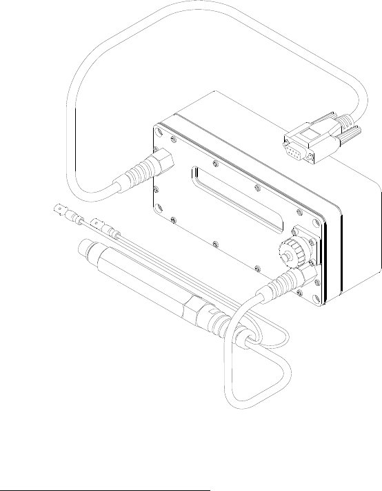
9. TEST BOX
The Test Box allows the user to test display system information of the Electric Remote,
RSTI, and Mini Controller Units as well as perform diagnostic checks. The Test Box
also serves as the programming interface between a computer and a RFD Unit.
Figure 9-1 Test Box
9.1. TEST BOX DESCRIPTIONS
9.1.1. Power Supply/Connector:
The Test Box is powered from an external +12VDC wall adapter. The adapter can be
configured for international use by choosing the correct power plug adapter. The default
plug adapter for your country was supplied with your kit.
9.1.2. Probe:
The Test Box has a probe that plugs into the Remote or Mini Controller under test. The
Test box communicates to the Unit under test through the probe and by using a radio
transmitter that is internal to the Test Box.
1678 RFD OPERATION MANUAL {DRAFT} 52

9.1.3. Serial Connection:
the
information displayed on the Test Box screen out the serial cable. A terminal program
such as Hyper Terminal may be set up to capture this information to a file. The file can
then be saved and printed.
9.2. TEST BOX OPERATION
A serial cable connects the Test Box to a computer serial port operating at 1200 baud.
The serial cable must be connected to a computer when the Test Box is being used to
program Mini Controller and Remote Units. The serial cable may also be used when
the Test Box is in the test mode. While in the test mode, the Test Box transmits
WARNING Do not touch the firing terminals of the Remote units while testing. A
potentially lethal voltage is present during the Fire test.
9.2.1. Test Box Messages
When the Test Box is turned on, the following message is displayed.
The “1678 Test Box” part of the message identifies the system types that the Test Box
is designed to operate with. “04/13/2011” is the date of the Test Box firmware. “Ver
3.0” is the version of the Test Box firmware. The Test Box will automatically step to the
next message “Connect Unit to Test”.
o the top connector on the Mini
Controller Unit. Then press the ‘ON’ Switch while pressing the Select ‘3’ switch. The
Mini Controller turns on with the yellow light next to the Select ‘3’ switch illuminated. The
Test Box will display the following message.
1678 Test Box
03/13/2011 Ver 3.0
Connect Unit to Test
9.2.2. Testing the Mini Controller
To test a Mini Controller Unit, plug the Test Box probe int
Mini Controller Detected
1678 RFD OPERATION MANUAL {DRAFT} 53

Next the Test Box will display the Battery Charge Count as shown below. This is the
number of charge cycles the battery within the Mini Controller has experienced.
he current battery’s temperature (+22C +72F) and
chemistry type (NiMH).
The next message shows the battery serial number (Battery SN 0001) and the battery’s
The next message displayed shows the assigned Frequency and the Message Number.
Next the Test Box displays t
Battery Charge Count
83
Battery Temp +22C +72F
Battery Type: 1400mAh NiMH
date of manufacture (Battery DOM 02/03/2011).
Battery SN 0001
Battery DOM 02/03/2011
The next message displayed shows the System Number or Address (0000000001) that
the Mini Controller is assigned to and the Unit assigned to the Mini Controller (Default is
Unit 1).
Address 0000000001
Unit 1
Frequency 174 MHz
Message Number 010000
1678 RFD OPERATION MANUAL {DRAFT} 54

The next message displayed is the Mini Controller’s serial number (S/N), unit Type
(Model) date of manufacture (DOM), firmware version (Ver).
Next the Mini Controller begins a Battery Test.
The Battery Test places a load on the battery and a countdown timer is started. At the
end of the test, the loaded battery voltage is displayed along with the test limit of (7.00).
After testing is complete, the following message is displayed.
9.2.3. Testing the Electric Remote
WARNING
S/N 00101 Type 1678-6
r 1.0 DOM 06/29/2010 Ve
The next message displayed is the firmware Checksum and the Fire Count.
Checksum 4C42
Fire Count 87
Battery Test – Standby
30
Loaded Battery 7.24
<Low Battery = 7.00>
Testing Completed
Do not touch the firing terminals of the Remote units while testing. A
potentially lethal voltage is present during the Fire test.
To test an Electric Remote, plug the Test Box probe into the top connector on the
Electric Remote. The Electric Remote turns on with the yellow light fast blinking and the
green light on. The Test Box will display the following message.
1678 RFD OPERATION MANUAL {DRAFT} 55

Next the Test Box will display the Battery Charge Count as shown below. This is the
number of charge cycles the battery within the Electric Remote has experienced.
Next the Test Box displays the current battery’s temperature (+22C +72F) and
dress (0000000001) and
the Unit number assigned to the Electric Remote.
The next message displayed shows the assigned Frequency and the Message Number.
Electric Remote Detected
Battery Charge Count
83
chemistry type (NiMH).
Battery Temp +22C +72F
Ah NiMBattery Type: 1650m H
The next message shows the battery serial number (Battery SN 0001) and the battery’s
date of manufacture (Battery DOM 02/03/2011).
Battery SN 0001
Battery DOM 02/03/2011
The next message displayed shows the System Number or Ad
Address 0000000001
Unit 2
Frequency 174 MHz
Message Number 010000
1678 RFD OPERATION MANUAL {DRAFT} 56

The next message displayed is the Electric Remote’s serial number (S/N), unit Type
(M , firmware version (Ver).
The next message displayed is the firmware Checksum and the Fire Count.
ic Arm/Fire Test. The Test Box Arms the
Electric Remote and begins 5 second countdown.
level is shown.
end of the test, the loaded battery voltage is displayed along with the test limit of (7.00).
odel) date of manufacture (DOM)
S/N 00101 Type 1678-6
DOM 06/29/2010 Ver 1.0
Next the Electric Remote begins the Electr
Checksum 4C42
Fire Count 87
At the end of the countdown the Electric Remote is fired. The firing voltage and pass
Electric Arm/Fire Test
05
Next the Electric Remote begins a Battery Test.
Arm/Fire Voltage 50.23
<Pass Level = 45.00>
Battery Test – Standby
30
The Battery Test places a load on the battery and a countdown timer is started. At the
1678 RFD OPERATION MANUAL {DRAFT} 57

Aing m ssage is displayed.
9.2.4.
Loaded Battery 7.24
<Low Battery = 7.00>
fter testing is complete, the follow e
Testing Completed
Testing the RSTI
WARNING Do not touch the firing terminals of the Remote units while testing. A
potentially lethal voltage is present during the Fire t
est.
To test an RSTI, install the firing tip on the top of the RSTI and plug the Test Box probe
in turns on with the yellow light fast blinking
aTest Box will display the following message.
Next the Test Box will display the Battery Charge Count as shown below. This is the
number of charge cycles the battery within the RSTI has experienced.
Next the Test Box dis battery’s temperature (+22C +72F) and
chemistry type (NiMH).
The next message shows the battery serial number (Battery SN 0001) and the battery’s
date of manufacture (Battery DOM 02/03/2011).
to the top connector on th
nd the green light on. The
e RSTI. The RSTI
RSTI Detected
Battery Charge Count
83
plays the current
Battery Temp +22C +72F
Battery Type: 1650mAh NiMH
1678 RFD OPERATION MANUAL {DRAFT} 58

Battery SN 0001
Battery DOM 02/03/2011
The next message displayed shows the System Number or Address (0000000001) and
the Unit that the RSTI is assigned to.
The next message dis shows the assigned Frequency and the Message Number.
del) date of
manufacture (DOM), firmware version (Ver).
unt.
ins 5
Address 0000000001
Unit 3
played
The next messages displayed are the serial number (S/N), unit Type (Mo
Frequency 174 MHz
Message Number 010000
S
D
/N 00101 Type 1678-3
OM 06/29/2010 Ver 1.0
The next message displayed is the firmware Checksum and the Fire Co
Checksum 4624
Fire Count 87
Next the RSTI begins the Arm/Fire Test. The Test Box Arms the RSTI and beg
second countdown.
RSTI Arm/Fire Test
05
At the end of the countdown, the RSTI fires resulting in the formation of a spark at the
tip. The firing voltage and pass level is shown.
1678 RFD OPERATION MANUAL {DRAFT} 59

Firing Voltage 2652
<Pass Level = 2250>
Next the RSTI begins a Battery Test.
The Battery Test places a load on the battery and a countdown timer is started. At the
Battery Test – Standby
30
end of the test, the loaded battery voltage is displayed along with the test limit of (7.00).
Loaded Battery 7.24
<Low Battery = 7.00>
After testing is complete, the following message is displayed.
Testing Completed
1678 RFD OPERATION MANUAL {DRAFT} 60
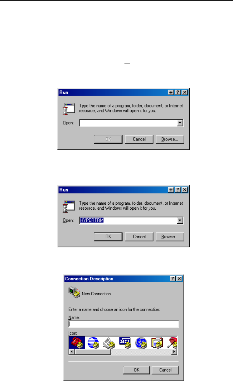
9.3. A FILE USING HYPERTERMINALSAVING TEST BOX RESULTS TO
A situation might occur where the end users want to be able to record the Test Box
results, but they may not be authorized to use the ‘RFD Test Utility’ program because of
case the output of the Test Box serial cable can
as HyperTerminal.
Cen click “R
its capability of reprogramming. In that
be captured to a terminal program such
lick the Windows “Start“ button, th un…”.
The dialog box shown below should appear.
Type “HYPERTRM” in the open box (without the quote marks)
button.
, and then click the “OK”
The dialog box shown below should appear.
1678 RFD OPERATION MANUAL {DRAFT} 61
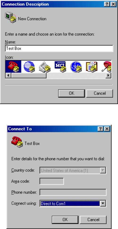
Enter a name and choose an icon for the connection. Click the “OK” button.
The dialog box shown below should appear.
1678 RFD OPERATION MANUAL {DRAFT} 62
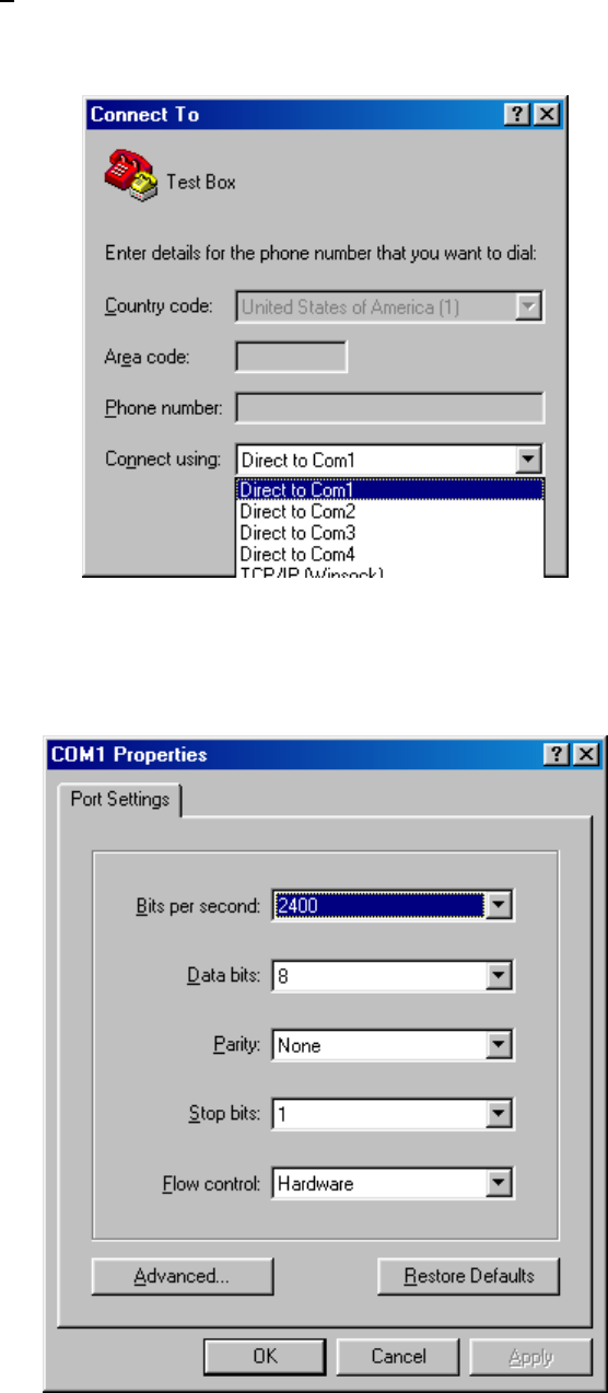
Click on the “Connect using:” list box and select either “Direct to Com1” or “Direct to
Com2”. Select the one that corresponds with an unused serial port connector on the
computer. Click the “OK” button.
The dialog box shown below should appear.
1678 RFD OPERATION MANUAL {DRAFT} 63
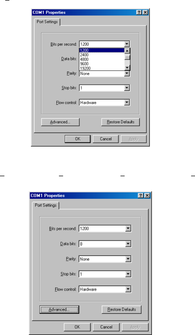
Click on the “Bits per second:” list box and select 1200.
Leave the “Data bits:” set to ‘8’, “Parity:” set to ‘None’, “Stop bits:” set to ‘1’, and “Flow
control:” set to ‘Hardware’ as shown in the following dialog box.
1678 RFD OPERATION MANUAL {DRAFT} 64
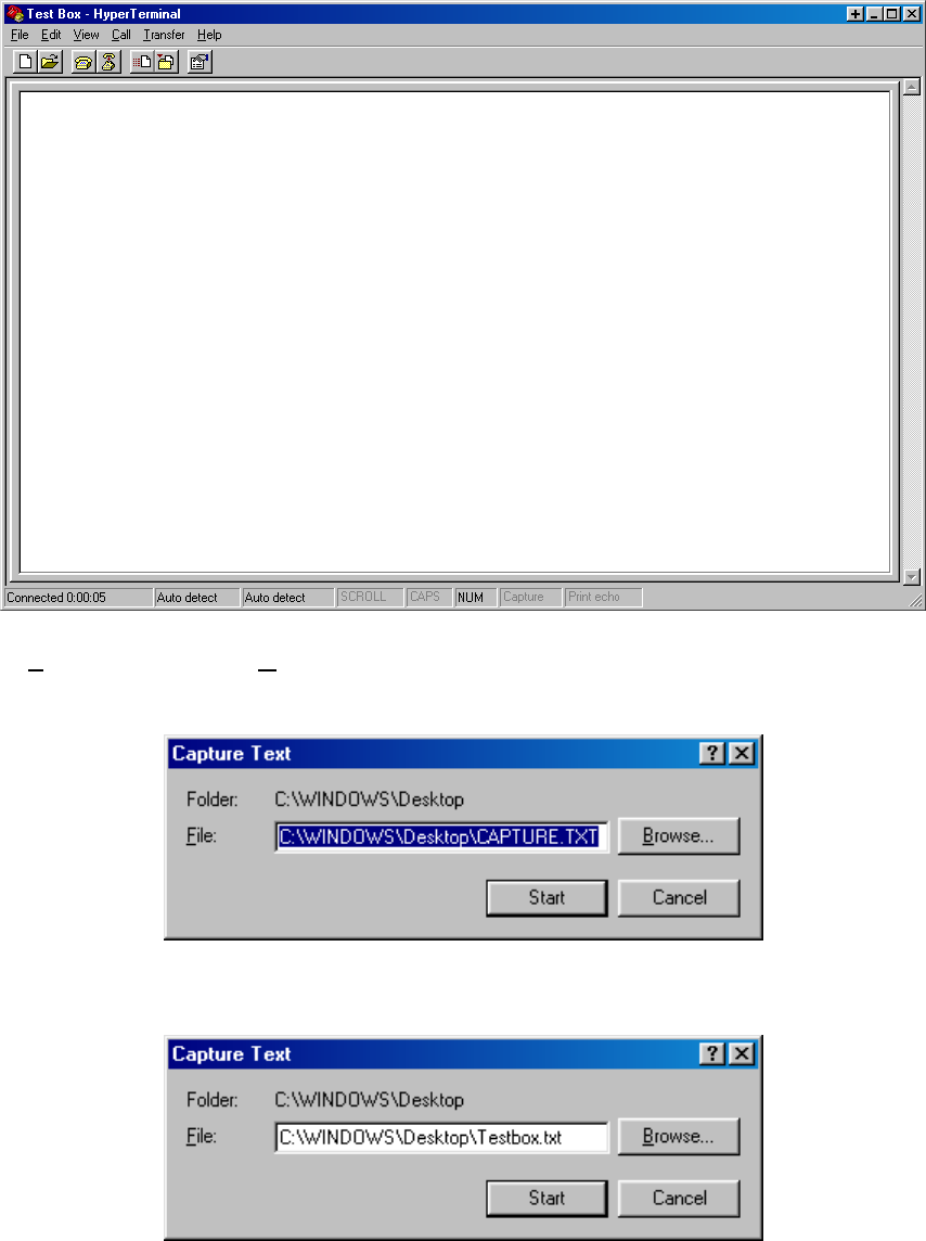
Click the “OK” button.
The dialog box shown below should appear.
Click “Transfer” and then “Capture Text…”. The dialog box shown below should
appear.
Enter a file name for the text output from the Test Box and click the “Start” button.
The dialog box shown below should appear.
1678 RFD OPERATION MANUAL {DRAFT} 65
Connect the Test Box serial cable to the serial port at the rear of the computer. This
serial port must match up with the earlier selection of either “Direct to Com1” or “Direct
to Com2”. Refer to documentation provided by computer manufacturer for more
information on available serial ports. Turn the Test Box on by installing its antenna.
The following text should appear in the window.
1678 RFD OPERATION MANUAL {DRAFT} 66
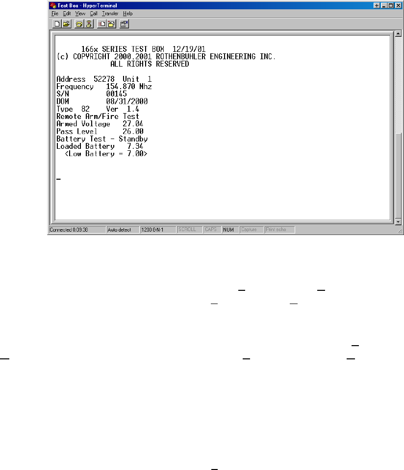
Proceed with testing the 1678 system.
The test results will be saved to a file. Select “File” and then “Print” to print the test
results to the computer’s printer. Select “File” and then “Save” to save this
onfiguration.
For future tests on the same computer, start HyperTerminal, Select “F
c
ile” and then
“Open”, select the configuration name. Select “Transfer” and then “Capture text…”. If
the same capture file name is used, the new test results will be appended to the end of
the previous test results.
Close the HyperTerminal window when the testing is completed.
If the above (or similar) text does not appear shortly after installing the Test Box
antenna, check that the serial cable is connected from the Test Box to the computer
correctly and that the selection under “Connect using:” matches the computer serial port
number that the Test Box serial cable is connected to.
1678 RFD OPERATION MANUAL {DRAFT} 67

10. RFD PROGRAMMING GUIDE
10.1. PROGRAMMABLE PARAMETERS
10.1.1. Mini Controller Unit
• Operating frequency: Frequency is programmable, but if the new frequency
is greater than 2MHz away from factory set frequency, the Mini Controller will
have to be retuned at a factory authorized service center for optimum
performance.
10.1.2. Remote Unit / RSTI
• Operating frequency: Frequency is programmable, but if the new frequency
is greater than 2MHz away from factory set frequency, the Remote Unit or
RSTI will have to be retuned at the factory for optimum performance.
• Unit ID: The Unit ID is a number from 1 to 4, and corresponds to the numbers
on the Mini Controller Unit keypad.
quency.
• Address: This is the address for the system. Remotes can be moved from
one system to another by matching up the system address and fre
10.2. REQUIRED EQUIPMENT
10.2.1. Test Box
10.2.2. A personal computer running Microsoft Windows® 95, 98, 2000, or XP and an
anual.
available DB-9 RS-232 serial port.
10.2.3. The software utility ‘Setup RFD’ located on the CD at the back of this m
10.3. WINDOWS CONFIGURATION SOFTWARE OPERATION (SETUP RFD)
Setup RFD is a Windows program designed for depot personnel to determine system
formation, make permissible changes to the system, and create a log file of test
10.4. SETUP RFD INSTALLATION
in
results.
The Setup RFD install files are distributed on a CD. Follow the listed steps to install
Setup RFD on a computer.
• Install the CD and browse to the file ‘Setup.exe’.
1678 RFD OPERATION MANUAL {DRAFT} 68
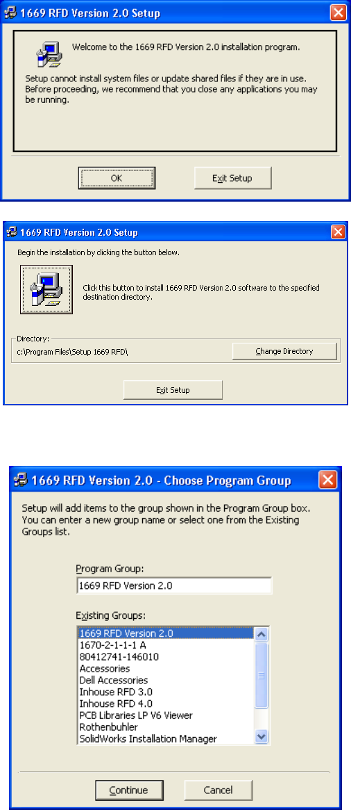
• Run the setup.exe file from the folder.
ear. Typical dialog boxes are
• Follow the prompts in the dialog boxes that app
shown below.
1678 RFD OPERATION MANUAL {DRAFT} 69
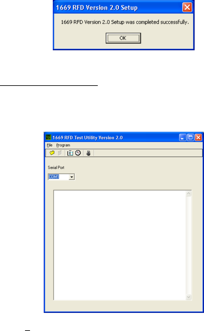
Setup 1669 RFD is now installed on the computer.
10.5. CONFIGURING SETUP RFD
Follow the listed instructions to configure Setup RFD.
• Click on the Windows “Start” button.
• Go to “Programs” then “Setup RFD” and then click on “Setup RFD”.
• The program will start and display the following dialog box.
• Click on the Serial Port list box and select the serial port that will be used with the
1678 Series RFD Test Box.
• The serial port selection will be retained for future sessions automatically.
• The Setup RFD program is now configured.
1678 RFD OPERATION MANUAL {DRAFT} 70
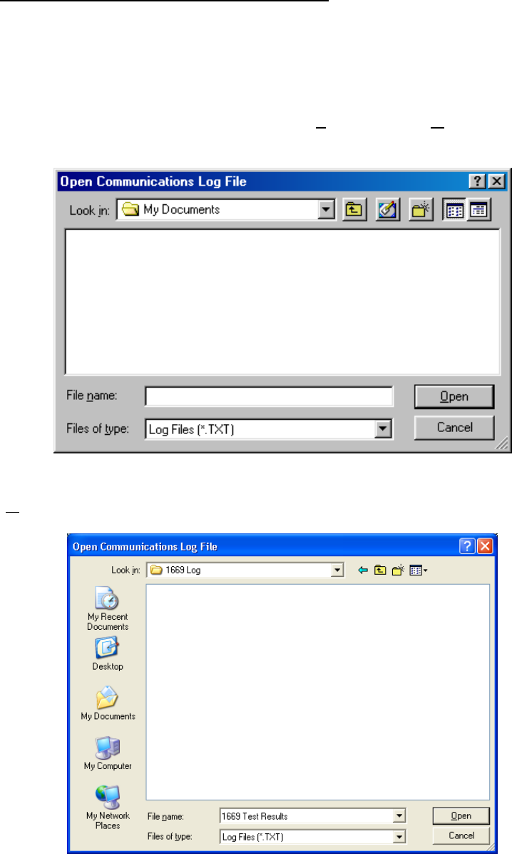
10.6. USING SETUP RFD TO TEST RFD UNITS
The Setup RFD program may be used with the 166x Series Test Box to test 166x
Series Units and record the results of those tests.
10.6.1. Creating a Test Results Log File:
• If a log file of test results is desired, click “File” and then “Open Log File…”. The
r. following dialog box will appea
• Type in a file name for the log file or select an existing file to use. Click the
“Open” button.
1678 RFD OPERATION MANUAL {DRAFT} 71
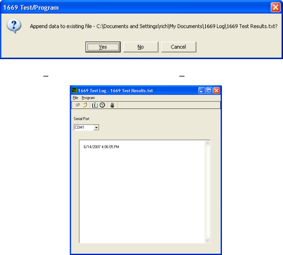
• If the file already exists, the following prompt appears.
Click “Y
•es” to append (add to) existing data or “No” to overwrite the existing file.
• The following window appears.
• A time and date stamp is added to the window.
• Notes can be added to the log file by clicking the note card icon and typing the
note in the dialog box that appears. Multiple notes can be added as required.
• Connect the Test Box serial cable to the serial port selected in a previous step.
• Turn on the Test Box by installing its antenna. The following window is
displayed.
1678 RFD OPERATION MANUAL {DRAFT} 72
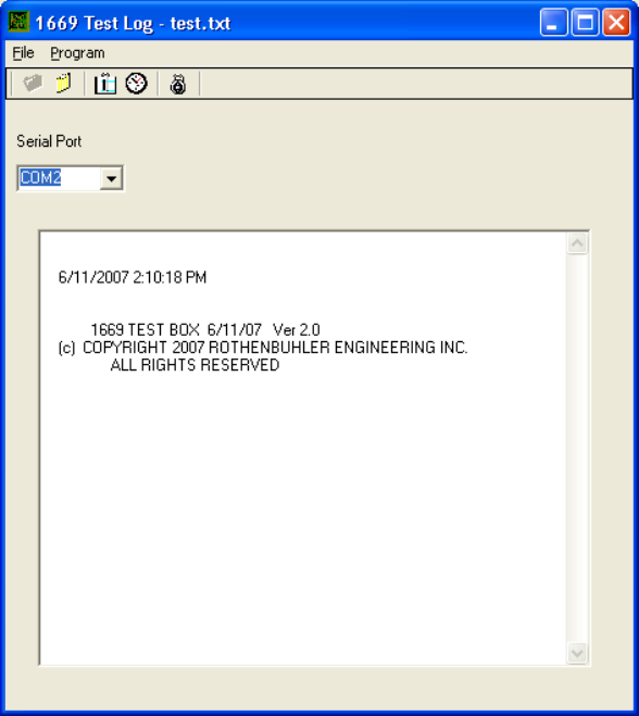
• Connect the Test Box Probe to a Remote Unit.
• Connect the Test Box Probe Leads to the Remote Unit binding posts. It does not
matter which lead goes to which binding post.
• The Test Box reads and displays the system information from the Remote Unit,
and then executes an arm/fire test followed by a battery test. The results are
displayed as shown in the next window.
1678 RFD OPERATION MANUAL {DRAFT} 73
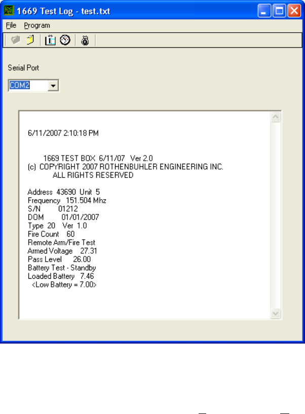
• To test the Remote Unit again, remove the Test Box Probe from the Remote Unit
for a few seconds, and then reconnect the Test Box Probe to the Remote Unit.
• To end the testing and save the log file, click “File” and then “Close Log File…”
1678 RFD OPERATION MANUAL {DRAFT} 74
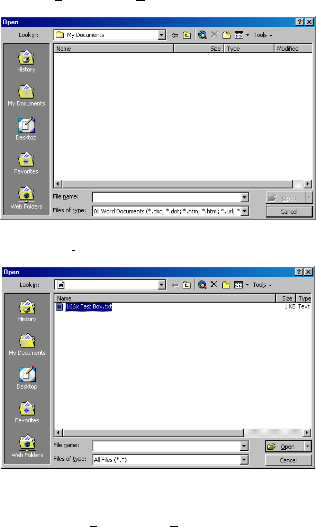
10.6.2. Printing Test Results to a Log File
• The log file must be printed from another Windows application such as Microsoft
Word.
• Start Word, click “File” and then “Open”.
• Change the “Files of type:” list box to “All Files (*.*)”
• Browse to the folder that contains the log file to print, and select the file.
• Print the file by clicking “File” and then “Print”.
1678 RFD OPERATION MANUAL {DRAFT} 75
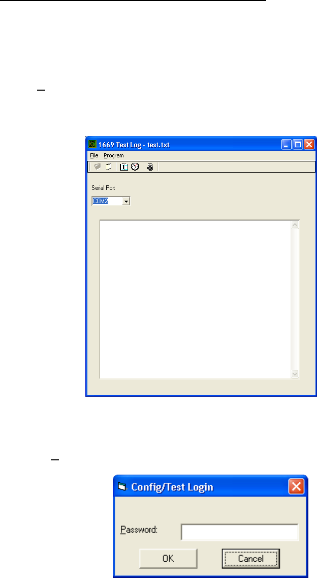
10.7. FD UNITSUSING SETUP RFD TO PROGRAM R
• Click on the Windows “Start” button.
• Go to “P
Follow the listed instructions to use Setup RFD to Program RFD Units.
rograms” then “Setup RFD” and then click on “Setup RFD”.
• The program will start and display the following dialog box.
• Click on the Serial Port list box and select the serial port that will be used with the
Series Test Box.
• Click on “Program” and the following window appears.
• For standard ‘User’ mode, click ‘Ok’. The pass
advanced features and the tune up mode. The
word protected mode is for
following screen should appear.
1678 RFD OPERATION MANUAL {DRAFT} 76
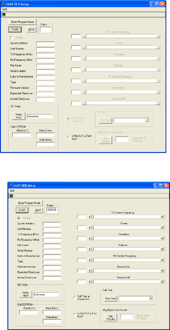
• Connect the Test Box Probe to the Unit to be programmed.
• The box labeled ‘Status’ updates automatically showing the type of unit
connected. 1669-1 and 1669-21 designate Mini Controllers, 1669-2 and 1669-20
designate Remotes, 1669-14 and 1669-19 designate RSTIs.
1678 RFD OPERATION MANUAL {DRAFT} 77
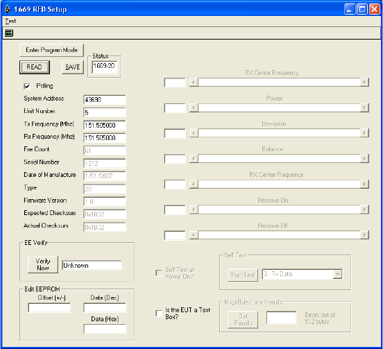
• With ‘Polling’ checked, the program will automatically read and display the unit’s
current settings.
• The “System Address” box displays the system address for the Unit. This
number is unique to each system.
• The “Unit Number” box displays the number for the Unit within the system.
Remotes will be 1 through 8 and the Mini Controller will be Unit 0.
• The “Frequency (MHz)” box displays the transmitter and receiver frequencies, in
Mega Hertz, for the Unit.
• The “Fire Count” box displays the number of times the Remote has been fired.
• The “Serial Number” box displays the Manufacturer’s serial number for the Unit.
• The “Date of Manufacture” box displays when the Unit was manufactured.
The “Type” box displays the Manufacture’s type code for the Unit.
• Boxes that are displayed in gray are not programmable and are for information
purposes only.
•
• The “Firmware Version” box displays the version of firmware that is programmed
into the Unit.
1678 RFD OPERATION MANUAL {DRAFT} 78
10.7.1. Changing the System Address
rogrammable only on Remote and RSTI Units. It may not be
changed on Mini Controller Units. The System Address should only be changed by
personnel having that authority. A possible scenario for changing the System Address
is that a Remote Unit in system 12345 has become unserviceable. A Remote Unit from
another system may be reprogrammed to have a System Address of 12345 to complete
the system. The Unit Number for the replacement Remote Unit should be
reprogrammed to match the Unit Number of the Remote Unit it is replacing.
To change the System Address follow the listed steps.
• Click on the “System Address” box and then type the desired System Address in
the box. Allowable entries are in the range of 1 to 65535.
• Press the “Enter” Key or click the mouse to another box.
• Click the “Read” button to re-read the Unit information and confirm that the
desired System Address was accepted.
10.7.2. Changing the Unit Number
The Unit Number is used to assign a unique
hin a
ck the mouse to another box.
• Click the “Read” button to re-read the Unit information and confirm that the
Units,
STIs, and RFD Test Box use to communicate with each other. All Units within a
o change the Frequency, follow the listed steps.
The System Address is p
ID to each Remote Unit within a system.
The same Unit Number should not be assigned to more than one Remote Unit wit
system.
To change the Unit Number follow the listed steps.
• Click on the “Unit Number” box and then type the desired Unit Number in the
box. Allowable entries are in the range of 1 to 8.
• Press the “Enter” Key or cli
desired Unit Number was accepted.
10.7.3. Changing the Frequency
The Frequency is the radio frequency that the Mini Controller Unit, Remote
R
system must have the same Frequency.
T
1678 RFD OPERATION MANUAL {DRAFT} 79
• Click on the “Frequency (MHz)” box and then type the desired Frequency in
Mega Hertz in the box for both the transmit (TX) and receive (RX) boxes.
ation and confirm that the
desired frequency was accepted.
or later), click the box
“Is EUT a Test Box” and perform the steps outlined above.
10.7.4. End of Programming
, perform a “Read” operation and
confirm all of the fields are entered as intended.
• Press the “Verify” button. This causes the unit to verify the integrity of all the data
hen all the changes are confirmed and verified, test the system by following the
Bench Test Procedure in Section 4.3.
Allowable entries are in the range of 150 to 174 Mega Hertz.
CAUTION Changes to the TX operating frequency by more than 2 MHz on either
side of the original frequency require retuning and must be performed by an authorized
service center.
• Press the “Enter” Key or click the mouse to another box.
• Click the “Read” button to re-read the Unit inform
• To change the frequency of the RFD Text Box (Version 2.0
• When programming has been completed
stored in the unit’s memory. Reprogram any fields that fail and re-verify.
• W
1678 RFD OPERATION MANUAL {DRAFT} 80

11. BATTERY MAINTENANCE
The battery packs will provide optimum performance and maximum life when the
following recommendations are adhered to.
11.1. BATTERY TEMPERATURE
10 and 30 degrees
y
For maximum efficiency charge batteries when they are between
Celsius. DO NOT attempt to CHARGE BATTERIES that are BELOW 0 degrees or
ABOVE 40 degrees Celsius. Permanent damage to batteries and or equipment ma
result.
11.2. PRE-OPERATION
Use the Battery Charger Assembly to discharge and then charge the battery of each
unit.
11.3. PERIODIC
Every two months perform two discharge and then charge cycles using the Battery
Charger Assembly on the battery of each unit.
11.4. ANNUAL
Have the battery packs replaced every 3 years or 300 charge / discharge cycles,
whichever comes first.
11.5. EXTENDED NON-USE
If the battery has not been discharged and charged within four months, repeat the
discharge / charge cycle four times and check the battery capacity prior to operational
use. Do not exceed storage temperature guidelines as it may reduce battery capacity
and/or cause physical deterioration of battery components.
Storage Time Storage Temperature
<30 days -4 to 122°F (-20 to +50°C)
30 - 90 days -4 to 104°F (-20 to +40°C)
>90 days -4 to 86 °F (-20 to +30°C)
1678 RFD OPERATION MANUAL {DRAFT} 81
1678 RFD OPERATION MANUAL {DRAFT} 82
Revision History: