Rotork Controls P3W-001 Pakscan 3 Wireless Field Control Unit User Manual Manual pt2
Rotork Controls Ltd Pakscan 3 Wireless Field Control Unit Manual pt2
Contents
- 1. Manual pt1
- 2. Manual pt2
- 3. Antenna Information
Manual pt2
Publication PUB059-002-00 Issue 05/12
P3 - Pakscan Master Station
Technical Manual

P3 - Pakscan Master Station Technical Manual
2 of 134 Publication PUB059-002-00 Issue 05/12
KNOW YOUR MASTER STATION
Port 3 Port 4
Port 3 Port 4
1 2 3 4 5
1 2 3 4 5
Host Ethernet
Ports for A
master station Connection to
wireless module
Port 1
Port 2
P
3
PS730
Keyswitch
Auto
A
B
P
3
P
3
PS720
IIE Loop
Standby
Port A
Port B
P
3
PS720
IIE Loop
Standby
Port A
Port B
P
3
PS710
Pakscan
P
3
Status
Pri/Stby
Power
Alarm
PS700
CPU/PSU
Port 1
Port 2
PS710
Pakscan
P
3
Status
Pri/Stby
Power
Alarm
Option 1
Option 2
Switch
A
B
CЄ
Option 2
Option 1
CPU/PSU
rotork
rotork
rotork
rotork
rotork
rotork
rotork
rotork
P3 Wireless
Comms
PS721
P3 Wireless
Comms
PS721
These modules not fitted on single master stations
Main
Chassis Host Comms
Serial Ports for A
master station
Host Comms
Serial Ports for B
master station
A side P3
CPU Main
Module
Optional
Wireless
Module
Optional
Current Loop
Module
Key Switch and
LTD Module
Optional
Current Loop
Module Optional
Wireless
Module
B side P3
CPU Main
Module
Power Connector Power Connector
View from below
Current
Loop
Connection
Terminals
Current Loop
Connection
Terminals (Single
Master Only)
Alarm and
ESD
Terminals Alarm and
ESD
Terminals
Host Ethernet
Ports for B
master station

Contents
Issue 05/12 Publication PUB059-002-00 3 of 134
CONTENTS:
KNOW YOUR MASTER STATION ............................................................................. 2
TABLE OF FIGURES:................................................................................................. 5
INTRODUCTION ......................................................................................................... 7
1. MOUNTING AND CONNECTING THE MASTER STATION .............................. 9
1.1 Mechanical Fixing ................................................................................................................ 9
1.2 Host Serial Communications Connections ....................................................................... 12
1.3 Ethernet Communications Connections ........................................................................... 12
1.4 Power Connector and Fuses ............................................................................................. 12
1.5 Alarm and Hardwired ESD Connector ............................................................................... 13
1.6 Current Loop Connections ................................................................................................ 13
1.7 Wireless Coordinator Connections ................................................................................... 14
1.8 Wireless Repeater and WMA AC Power Connections ...................................................... 15
1.9 WMA (Wireless Modbus Adapter) 24VDC Connections.................................................... 16
1.10 WMA (Wireless Modbus Adapter) Modbus Connections................................................ 16
1.11 Setting up the Wireless Repeater and WMA ................................................................... 17
1.12 Front Panel LEDs ............................................................................................................. 20
2. THE FIELD CURRENT LOOP NETWORK ....................................................... 21
2.1 Loop Checks....................................................................................................................... 22
2.2 Connecting Up .................................................................................................................... 23
3. THE FIELD WIRELESS NETWORK................................................................. 25
3.1 Wireless Site Survey .......................................................................................................... 26
3.2 Wireless Specification ....................................................................................................... 26
3.3 Connecting Up .................................................................................................................... 26
4. CONFIGURING SERIAL COMMUNICATIONS ................................................ 29
4.1 Setting Port 1 and 2 for RS-232 or RS-485 ........................................................................ 29
5. CONFIGURING ETHERNET COMMUNICATIONS .......................................... 33
5.1 Default Ethernet Settings ................................................................................................... 34
5.2 Ethernet Security................................................................................................................ 35
6. SETTING UP THE MASTER STATION BY THE KEYPAD .............................. 37
6.1 Using the Keypad ............................................................................................................... 37
6.2 The Screen Display ............................................................................................................ 38
6.3 Setting the Current Loop Option Module Parameters ...................................................... 39

P3 - Pakscan Master Station Technical Manual
4 of 134 Publication PUB059-002-00 Issue 05/12
6.4 Setting the Wireless Option Module Parameters .............................................................. 43
6.5 Setting the Master Host Communications Parameters..................................................... 45
6.6 The Other Settings ............................................................................................................. 47
6.6.1 Security .......................................................................................................... 47
6.6.2 ESD ............................................................................................................... 47
6.6.3 Date and Time ................................................................................................ 47
6.6.4 Master Station Parameters ............................................................................. 48
7. INTERNAL WEB PAGES ................................................................................. 49
7.1 Making an Internet / Intranet Connection .......................................................................... 49
7.2 Connecting a Computer Directly to the Master Station .................................................... 50
7.3 Adjusting the Network Settings of the Computer ............................................................. 50
7.4 Web Page Structure ........................................................................................................... 52
7.4.1 User Levels .................................................................................................... 52
7.4.2 Overview of Web Page Layout........................................................................ 52
7.5 The Web Pages in Detail .................................................................................................... 54
7.5.1 Log In Screen ................................................................................................. 54
7.5.2 Master Station ................................................................................................ 55
7.5.3 View Configuration ......................................................................................... 57
7.5.4 System Diagnostics ........................................................................................ 58
7.5.5 Master Station Data Logger [ms datalogger] ................................................... 60
7.5.6 Master Station Host Analyser [host analyser] .................................................. 62
7.5.7 Pakscan 2 Loop Diagnostics [diagnostics] ...................................................... 63
7.5.8 Pakscan Wireless Diagnostics [diagnostics] .................................................... 66
7.5.9 Pakscan 2 Loop Option Module Event Logger [Event Log] .............................. 68
7.5.10 Pakscan Wireless Option Module Event Logger [Event Log] ........................... 69
7.5.11 FCU Menu ...................................................................................................... 70
7.5.12 FCU Control – IQ / IQT Actuator ..................................................................... 71
7.5.13 FCU Control - Integral Actuator (2-wire loop only) ........................................... 80
7.5.14 FCU Control - General Purpose Field Control Unit (2-wire loop only) .............. 84
7.5.15 Admin ............................................................................................................. 88
7.5.16 Users ............................................................................................................. 88
7.5.17 Master station Configuration ........................................................................... 91
7.5.18 Host Port Configuration ................................................................................ 100
7.5.19 Alarms .......................................................................................................... 105
7.5.20 Time ............................................................................................................. 107
7.5.21 General ........................................................................................................ 108
7.5.22 Network ........................................................................................................ 109
7.6 Setting Up the Master station Configuration Using the Web Pages .............................. 111
7.6.1 Masterstation Config - Modbus Address ....................................................... 111
7.6.2 Masterstation Config - Pakscan 2 Current loop option ................................... 111
7.6.3 Masterstation Config - Pakscan 3 Wireless option ......................................... 112
7.6.4 Host port settings ......................................................................................... 112
7.6.5 Network IP address settings ......................................................................... 113
8. MAKING THE SYSTEM WORK ..................................................................... 115
8.1 Commissioning the Wired System .................................................................................. 115
8.2 Commissioning the Wireless network ............................................................................. 116

Contents
Issue 05/12 Publication PUB059-002-00 5 of 134
8.3 Monitoring and Controlling the Actuators from the HMI or web pages ......................... 117
9. LONG TERM DATALOGGER (LTD) .............................................................. 119
9.1 Removing the memory card and copying data ............................................................... 120
9.2 Viewing the data with the LTD Viewer software .............................................................. 122
9.2.1 Messages ..................................................................................................... 123
9.2.2 Messages – Filter Options ............................................................................ 123
9.2.3 Reports ........................................................................................................ 126
9.2.4 FCU Data ..................................................................................................... 127
10. RESETTING THE MASTER STATION TO DEFAULT VALUES .................... 128
10. REPLACING THE P3 MASTER STATION BATTERY ................................... 130
GENERAL SAFETY INFORMATION ...................................................................... 131
TABLE OF FIGURES:
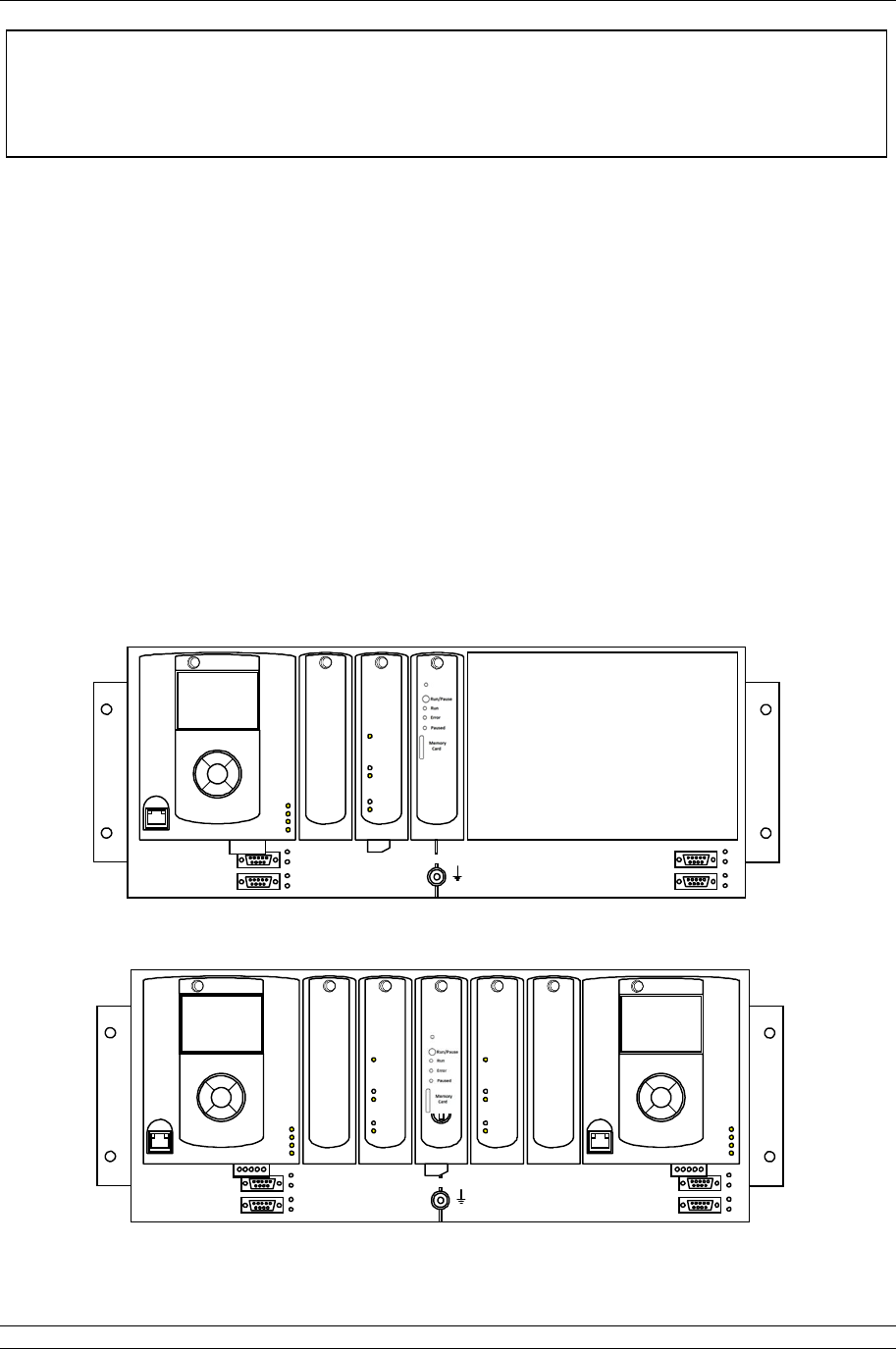
Fig 1: The Pakscan 3 Single Master Station – option: Current loop ............................................7
Fig 2: The Pakscan 3 Hot Standby Master Station - option: Current loop ...................................7
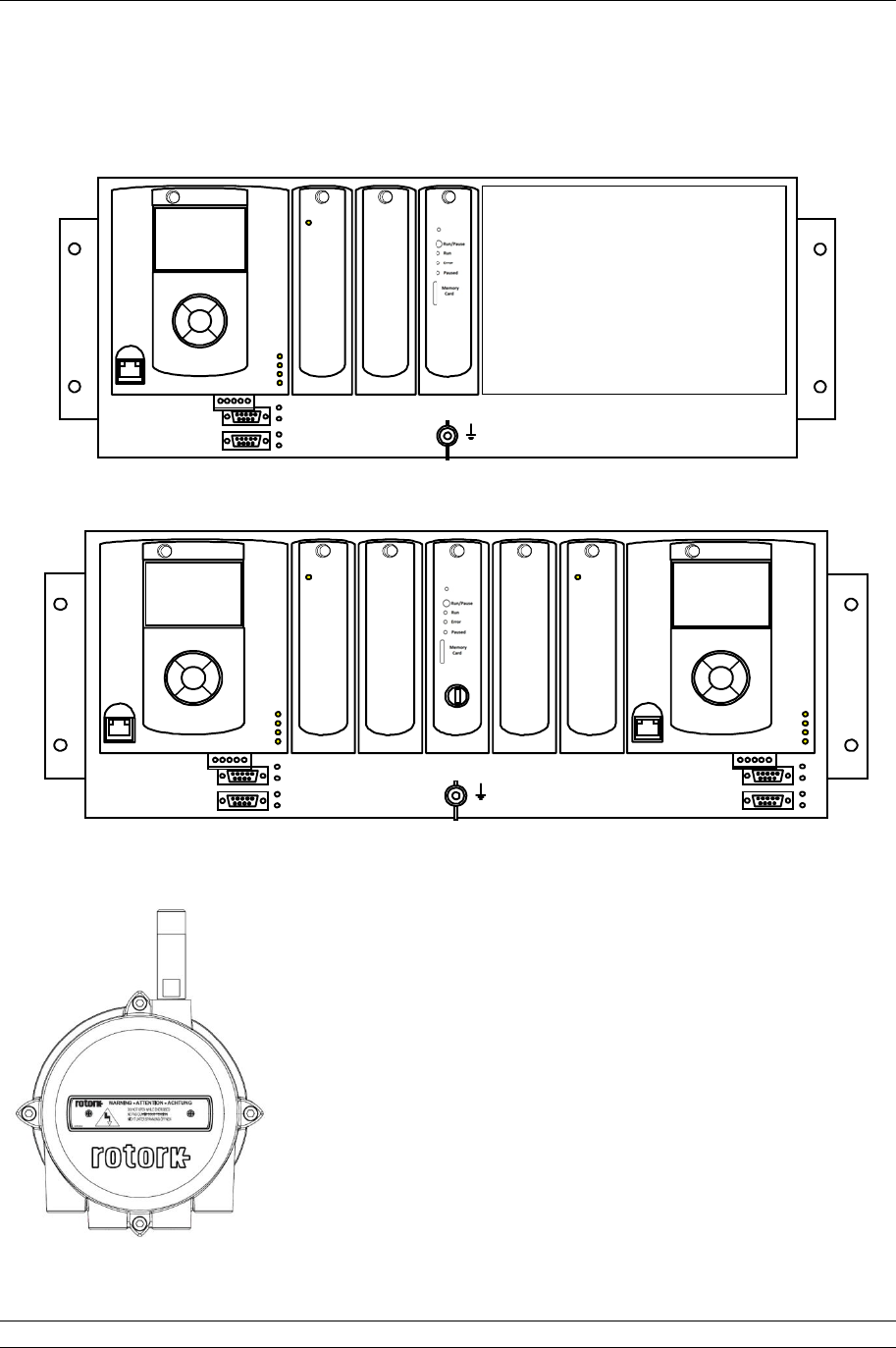
Fig 3: The Pakscan 3 Single Master Station – option: Wireless ..................................................8
Fig 4: The Pakscan 3 Hot Standby Master Station – option: Wireless ........................................8
Fig 5: The Pakscan 3 Wireless master station coordinator – PS722...........................................8
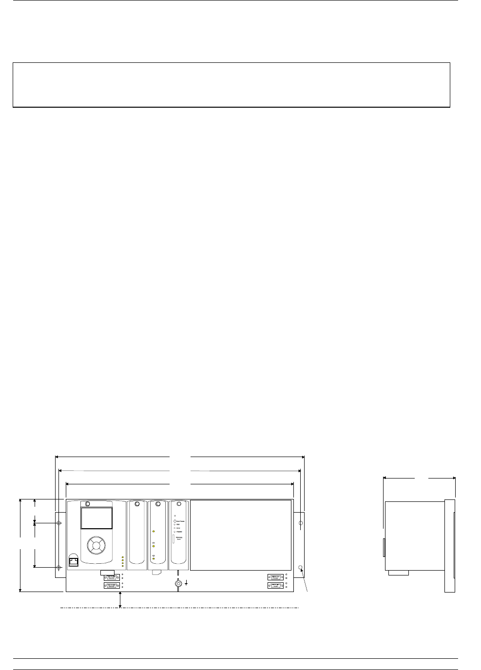
Fig 6: Pakscan 3 surface mounting dimensions. ........................................................................9
Fig 7: Pakscan 3, 19-inch rack mounting dimensions............................................................... 10
Fig 8: View below the Pakscan P3 master station showing the Connectors ............................. 10
Fig 9: Wireless co-ordinator WMA and Repeater mounting details ........................................... 11
Fig 10: Serial Communication connections ................................................................................ 12
Fig 11: PS710 CPU module connector terminal functions .......................................................... 13
Fig 12: PS720/PS730/PS731/PS732 Current Loop connections ................................................ 13
Fig 13: PS721 to PS722 connections (Master station to Wireless Coordinator) .......................... 14
Fig 14: Power module for Wireless Repeater and WMA. ........................................................... 15
Fig 15: PS721 to PS722 connections (Master station to Wireless Coordinator) .......................... 16
Fig 16: Wireless Repeater and WMA database ......................................................................... 18
Fig 17: Wireless Repeater and WMA database ......................................................................... 19
Fig 18: CPU LEDs (Light Emitting Diodes) ................................................................................ 20
Fig 19: Pakscan P3 Wired Network ........................................................................................... 21
Fig 20: Pakscan P3 Current Wired Loop System Block Diagram (hot standby master station) .......... 23
Fig 21: Pakscan P3 Current Wired Loop System Block Diagram (single master station) ................... 24
Fig 22: A typical P3 wireless network ........................................................................................ 25
Fig 23: Pakscan P3 Wireless network Block Diagram (hot standby master station) .................... 27
Fig 24: Pakscan P3 Chassis, CPU and Key Switch modules removed ....................................... 29
Fig 25: Port Function Switches shown in RS-232 position ......................................................... 30
Fig 26: Port Termination Switches shown in Off position............................................................ 30
Fig 27: Cross connection switch settings on the backplane behind the Switch Module ............... 31
Fig 28: Hot Standby Serial Communications.............................................................................. 32
Fig 29: Hot Standby Ethernet Communications ......................................................................... 33
Fig 30: Hot Standby, Dual Redundant Ethernet Communications .............................................. 34
Fig 31: Pakscan P3 Main module connection to laptop and keypad detail .................................. 37
Fig 32: Connecting a Laptop to the Pakscan P3 Main Module ................................................... 50

P3 - Pakscan Master Station Technical Manual
6 of 134 Publication PUB059-002-00 Issue 05/12
Fig 33: Changing the Network Connections TCP/IP Properties – Windows XP .......................... 51
Fig 34: Web Page Menu Layout ................................................................................................ 53
Fig 35: Web page Log In Screen ............................................................................................... 54
Fig 36: Web page Header Navigation ........................................................................................ 54
Fig 37: Master Station Overview web page and Option 1 data, if a Wireless module is fitted ...... 55
Fig 38: System Configuration Overview web page ..................................................................... 57
Fig 39: System Diagnostics web page wired only and option 1 data, if wireless fitted ................. 58
Fig 40: Master Station Data Logger pop-up ............................................................................... 60
Fig 41: Close up of Master Station Data Logger Information ...................................................... 60
Fig 42: Saving the master station log file ................................................................................... 61
Fig 43: Host Analyser pop-up .................................................................................................... 62
Fig 44: Pakscan 2 Loop Diagnostics web page ......................................................................... 63
Fig 45: Pakscan Wireless Diagnostics web page ....................................................................... 66
Fig 46: Wired Option Module Event Logger pop-up ................................................................... 68
Fig 47: Wireless Option Module Event Logger pop-up ............................................................... 69
Fig 48: FCU Menu web page .................................................................................................... 70
Fig 49: IQ and IQT actuator FCU Control web pages ................................................................. 71
Fig 50: Wired IQ / IQT Parameters pop-up ................................................................................ 72
Fig 51: Wired IQ / IQT Alarms pop-up ....................................................................................... 73
Fig 52: Wired and Wireless IQ / IQT Torque Profile pop-up ....................................................... 73
Fig 53: Wired IQ / IQT FCU Event Log pop-up .......................................................................... 74
Fig 54: Wireless IQ / IQT Parameters pop-up ............................................................................ 75
Fig 55: Wireless IQ / IQT Alarms pop-up ................................................................................... 76
Fig 56: Wireless IQ / IQT FCU Event Log pop-up ...................................................................... 77
Fig 57: Wireless IQ / IQT Downloads pop-up ............................................................................. 78
Fig 58: Wireless Neighbour tables pop-up ................................................................................. 78
Fig 59: Q actuator FCU Control Web page ................................................................................ 80
Fig 60: Q Parameters pop-up .................................................................................................... 81
Fig 61: Q Alarms pop-up ........................................................................................................... 82
Fig 62: Q FCU Event Log pop-up .............................................................................................. 82
Fig 63: GPFCU Control web page ............................................................................................. 84
Fig 64: GPFCU Parameters pop-up .......................................................................................... 85
Fig 65: GPFCU Alarms pop-up .................................................................................................. 86
Fig 66: GPFCU Event Log pop-up ............................................................................................. 86
Fig 67: Administrator Level........................................................................................................ 88
Fig 68: Users web page ............................................................................................................ 88
Fig 69: Add User web page ....................................................................................................... 89
Fig 70: Modify User web page ................................................................................................... 90
Fig 71: Master station configuration web page: General Settings ............................................... 91
Fig 72: Web page Field unit distribution bar ............................................................................... 95
Fig 73: Master station configuration web page: Pakscan 2 Loop ................................................ 96
Fig 74: Master station configuration web page: Pakscan 3 Wireless .......................................... 98
Fig 75: Host Port Configuration web page ............................................................................... 100
Fig 76: Modbus Message Generator web page ....................................................................... 103
Fig 77: Modbus Message Example web page ......................................................................... 104
Fig 78: Alarm Reporting Set up web page ............................................................................... 105
Fig 79: Time Settings web page .............................................................................................. 107
Fig 80: General web page ....................................................................................................... 108
Fig 81: Ethernet Network Settings web page ........................................................................... 109
Fig 82: Detailed Actuator Condition HMI pages ....................................................................... 117
Fig 83: Hot standby master station with Long Term Datalogger (LTD) ..................................... 119
Fig 84: Front view of the LTD .................................................................................................. 120
Introduction
Issue 05/12 Publication PUB059-002-00 7 of 134
Port 1
Po
rt 2
P
3
PS730
Keyswitch
Auto
A
B
P
3
P
3
PS720
IIE Loop
Standby
Port A
Port B
P
3
PS720
IIE Loop
Standby
Port A
Port B
P
3
PS710
Pakscan
P
3
Status
Pri/Stby
Power
Alarm
PS700
0
CPU/PSU
Port 1
Port 2
PS710
Pakscan
P
3
Status
Pri/Stby
Power
Alarm
Option 1
Option 2
Switch
A
B
CЄ
Option 2
Option 1
CPU/PSU
rotork
rotork
rotork
rotork
rotork rotork
rotork
rotork
Port 1
Port 2
Port 1
Port 2
P
3
P
3
PS720
IIE Loop
Standby
Port A
Port B
PS700
CPU/PSU
PS710
Pakscan
P
3
Status
Pri/Stby
Power
Alarm
Option 1
Option 2
Switch
A
B
CЄ
Option 2
Option 1
CPU/PSU
rotork
rotork rotork rotork
P
rotork
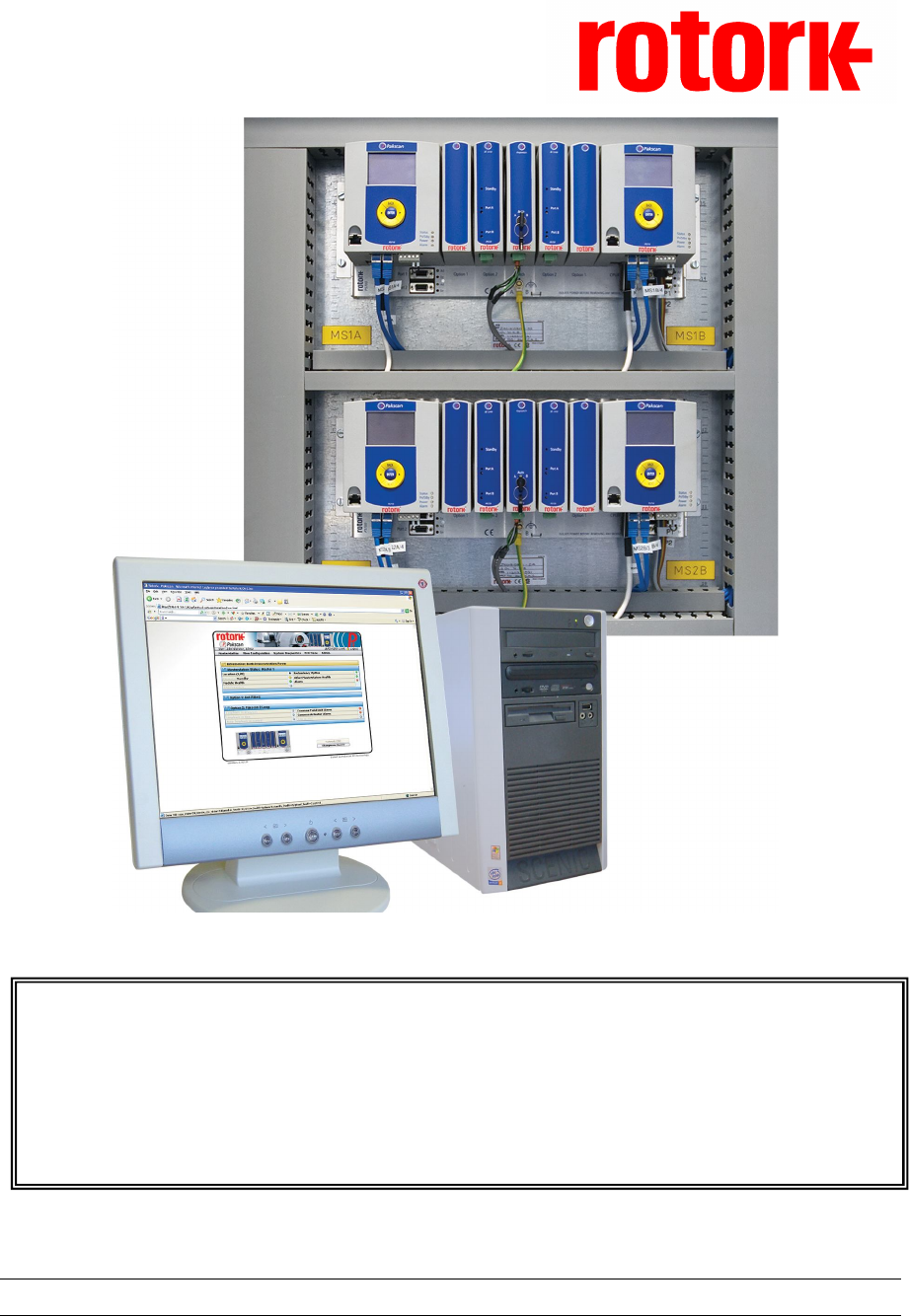
INTRODUCTION
Pakscan 3 is a complete field network control system from Rotork. With the addition of a wireless
network the user now has the choice of proven current loop technology of the Pakscan IIE system or
the flexibility of a meshed wireless network.
This manual provides a guide to setting up the Pakscan master station, the loop communications,
wireless communications, and the host connections for the most commonly found applications.
Most types of Rotork actuator can be connected to a Pakscan current loop provided they are fitted
with the necessary field unit. Information on the respective actuator field units can be found in the
appropriate manuals. In this guide, the type of actuator is not considered, though reference is made to
both the Integral and IQ actuator types of field unit. The type of field unit does not affect the setting up
of the system. The IQ and IQT range of actuator integrate fully with the wireless network. Other
actuators or devices can be added to the system using a Wireless Modbus Adaptor (WMA).
Pakscan 3 master stations are delivered either as loose items for mounting by the user, or contained
in an enclosure provided by Rotork. The master station will generally be either a single unit, or a hot
standby pair.
Fig 1: The Pakscan 3 Single Master Station – option: Current loop
Fig 2: The Pakscan 3 Hot Standby Master Station - option: Current loop
This manual relates to Pakscan 3 Master Stations fitted
with PS720 Current Loop modules and/or the PS721 and
PS722 Wireless modules
P3 - Pakscan Master Station Technical Manual
8 of 134 Publication PUB059-002-00 Issue 05/12
A master station fitted with the wired network only requires the PS720 module that fits in to the back
plane. A master station fitted with wireless requires a module to be fitted to the back plane (in option
1) and connected to this module, a coordinator module (PS722).
Fig 3: The Pakscan 3 Single Master Station – option: Wireless
Fig 4: The Pakscan 3 Hot Standby Master Station – option: Wireless
Fig 5: The Pakscan 3 Wireless master station coordinator – PS722.
One required for single channel master stations, two for hot standby
master stations. The repeater (a device for extending the range of
wireless) and the WMA look identical to this.
Port
Port
P
3
PS730
Keyswit
Aut
A
B
P
3
P
3
P
3
PS720
P
3
PS710
Pakscan
P
3
Statu
Pri/Stb
Pow
Alar
PS700
CPU/PS
Port
Port
PS710
Pakscan
P
3
Statu
Pri/Stb
Pow
Alar
Option
Option
Switc
A
B
CЄ
Option
Option
CPU/PS
rotork
rotork
rotork
rotork
rotork
rotork
rotork
rotork
P3
Comms
PS721
P3
Comms
PS721
P
3
P
3
P
3
3
PS700
CPU/PSU
Port 1
Port 2
PS710
Pakscan
P
3
Status
Pri/Stby
Power
Alarm
Option 1
Option 2
Switch
A B
CЄ
rotork
rotork rotork rotork
rotork
P3 Wireless
Comms
PS721
1. Mounting and Connecting the Master Station
Issue 05/12 Publication PUB059-002-00 9 of 134
1. MOUNTING AND CONNECTING THE MASTER STATION
The Pakscan 3 master station (single or hot standby) provides front access for all the user
connections, including power feed and the field network connections – either loop wires to the Current
Loop module (PS720) or network connection to the Wireless coordinator (PS721 and PS722). The
host communication links use plug in D-type connectors for the serial communications and RJ45
connections for the Ethernet links.
The field wiring for the current loop, wireless coordinator and the master station alarms are
taken to screw terminals on plug in connectors that are fitted from below their appropriate
module.
Power wiring is connected using an IEC connector in the bottom of the master station module
PS710. Two connections are required for a hot standby system.
Serial communications (RS-232 or RS-485) plug into 9 way female D-type connectors on the
front of the mounting chassis.
Ethernet connections use RJ45 connectors on the bottom of the master station module
PS710. The connector on the front is intended for connection to a service laptop computer.
1.1 Mechanical Fixing
Room should be left around the module for all the connections and cables, allowing for a suitable
bending radius on each lead. Power wiring should be suitably fused or protected with miniature circuit
breakers (MCBs) external to the master station.
The master station may be mounted on a flat surface using the mounting brackets provided. Also, the
extension brackets allow it to be mounted in a 19-inch rack. In either case it should be located in a
way that permits easy access to the pushbuttons and easy viewing of the display panel(s).
Before mounting the master station, set the communications link
switches, as discussed in section 3.
178
45
88
482
467
438
140
4 holes 6.5
All dimensions in mm
Allow 30 mm minimum space for cabling
Port 1
Port 2
Port 1
Port 2
P
3
P
3
PS720
IIE Loop
Standby
Port A
Port B
PS700
CPU/PSU
PS710
Pakscan
P
3
Status
Pri/S
t
by
Power
Alarm
Option 1
Option 2
Switch
A BCЄ
Option 2
Option 1
CPU/PSU
rotork
rotork
rotork
rotork
Fig
6
:
Pakscan 3 surface mounting dimensions.
(Both single and hot standby master stations may be surface mounted)
P
rotork

P3 - Pakscan Master Station Technical Manual
10 of 134 Publication PUB059-002-00 Issue 05/12
All dimensions in mm
178
38
102
482
466
4 slots 6.5
Allow 30 mm minimum space for cabling
Port 1
Port
2
P
3
PS730
Keyswitc h
Auto
A
B
P
3
P
3
PS720
IIE Loop
Standby
Port A
Port B
P
3
PS720
IIE Loop
Standby
Port A
Port B
P
3
PS710
Pakscan
P
3
Status
Pri/Stby
Power
Alarm
PS700
0
CPU/PSU
Port 1
Port
2
PS710
Pakscan
P
3
Status
Pri/Stby
Power
Alarm
Option 1
Option 2
Switch
A
B
CЄ
Option 2
Option 1
CPU/PSU
rotork
rotork
rotork
rotork
rotork
rotork
rotork
rotork
140
133
Fig
7
:
Pakscan 3, 19
-
inch
rack mounting dimensions.
(Both single and hot standby master stations can be panel or rack mounted)
Fig
8
:
View below the Pakscan P3 master station showing the Connectors
(The B side connections are similar)
Port 3 Port 4 1 2 3 4 5
1 2 3 4 5 6
IEC Power
Connector
Ethernet
Ports
Hard Wired
ESD Serial
Ports Current
Loop
Fuses
(Hot Standby)
(Single)
Wireless
module
1
2
3
4
5
6
7
8
1. Mounting and Connecting the Master Station
Issue 05/12 Publication PUB059-002-00 11 of 134
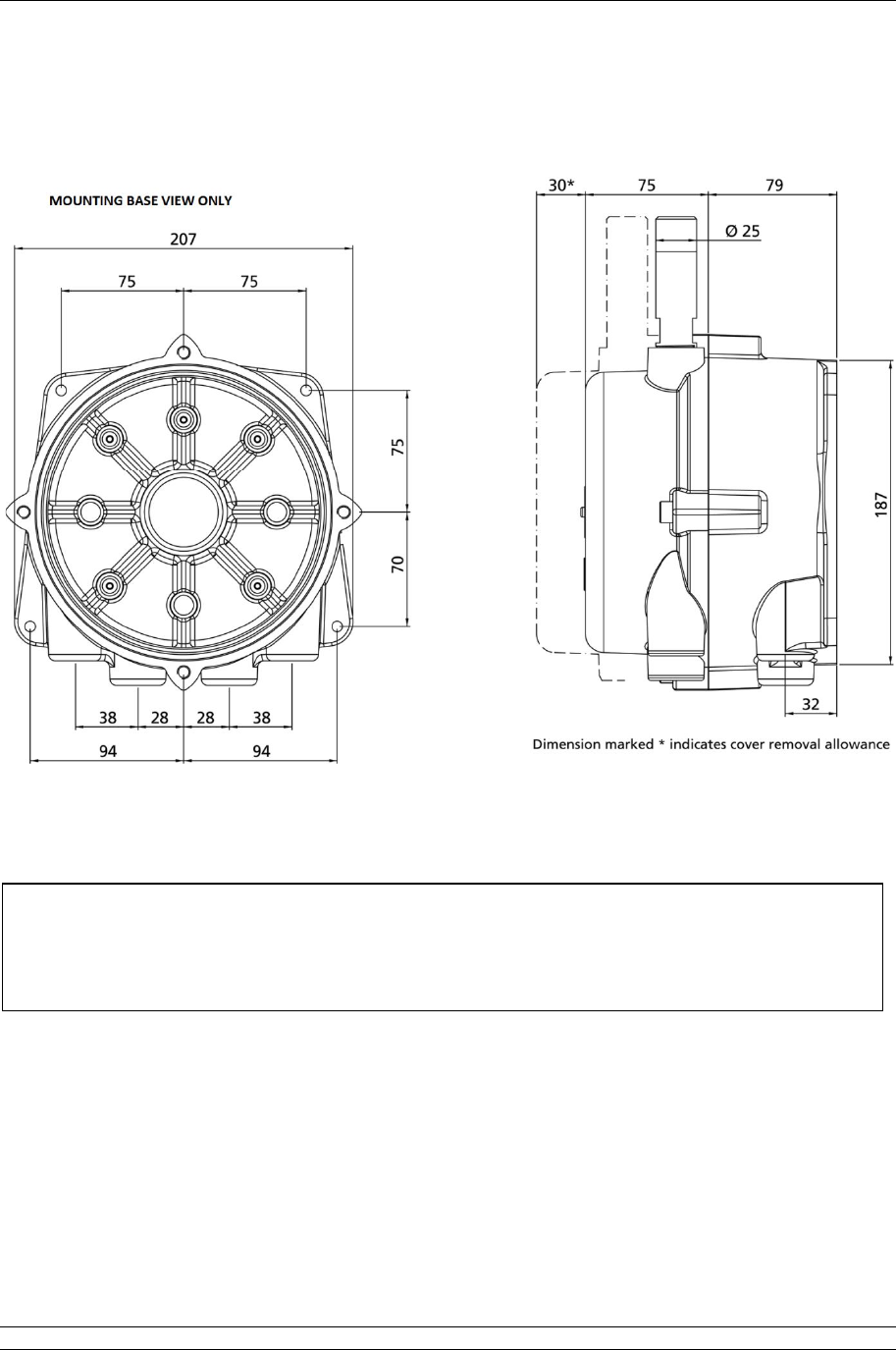
Wireless installations will include a Wireless Coordinator and may include Wireless Repeaters and
Wireless Modbus Adaptor. These units are identical with regards to mechanical fixing.
Dimensions in mm, Module weight: 4,400g
Fig 9: Wireless co-ordinator WMA and Repeater mounting details
The Wireless Coordinator, Wireless Repeater and Wireless modbus
Adaptor may be located in Hazardous locations. If this is the case, please
refer to the Hazardous Area notes in the General Safety Information section
at the back of this manual.

P3 - Pakscan Master Station Technical Manual
12 of 134 Publication PUB059-002-00 Issue 05/12
1.2 Host Serial Communications Connections
The serial data connections are via the D-type connectors below each master station PS710 on the
main chassis. They are labelled Port 1 and Port 2 on both the A and B (left and right) sides of the
assembly. All the connectors are 9 way female and they may be set for RS-485 (2-wire) or RS-232
use. On hot standby systems they can be cross coupled to provide seamless communication when the
systems change over. The pin-out connections are shown below.
With RS-485 it is possible to arrange a multi-drop data highway for the serial communications,
whilst RS-232 must be single point communications.
1.3 Ethernet Communications Connections
Each Pakscan P3 CPU module (master station module) has 2 x RJ45 Ethernet connectors for the two
host communication ports (accessed from below) marked Port 3 and Port 4. A third RJ45 connector is
located on the front of each module. This is provided to allow a portable computer (laptop) to be
connected for diagnostic and set up purposes. Standard Ethernet patch cables can be used with these
connectors.
All Ethernet cables must be screened, and of good quality. Many screened Ethernet cables of low
quality have questionable screening efficacy.
1.4 Power Connector and Fuses
Each Pakscan P3 CPU module has its own internal power supply. A standard IEC connector is
provided to allow the mains power (85 to 263V AC – 47 to 63 Hz) to be connected from below the
module. The mains IEC socket also includes the two fuses for the system, which must only be
replaced with the same and rating 250V 1A 5x20mm anti-surge fuses.
For the 24V DC version, a three pin removable screw terminal connector is provided. There is no
internal fuse.
Fig 10: Serial Communication connections
1. Mounting and Connecting the Master Station
Issue 05/12 Publication PUB059-002-00 13 of 134
Port A OUT
Port A IN
Screen
Port B OUT
Port B IN
Screen
5
4
6
2
1
3
PS720/PS730
CONNECTOR
Source A
Source B
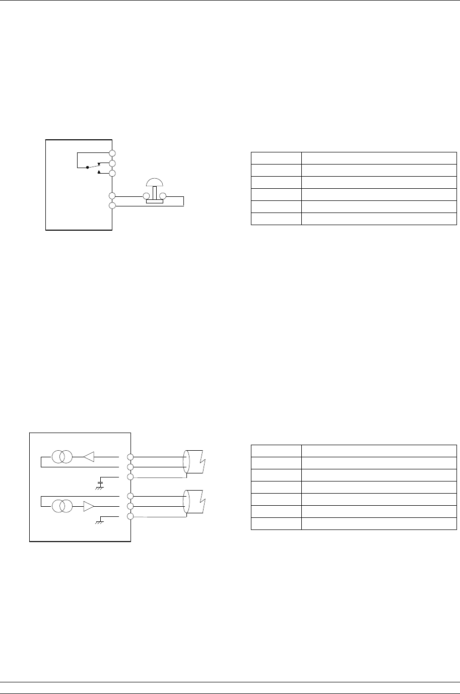
1.5 Alarm and Hardwired ESD Connector
There is a removable screw terminal connector in each Pakscan P3 CPU module for the connection of
ESD hard-wired inputs and for connection to the internal alarm relay contacts, when required. On
most systems these terminals will not be used; in which case a hard-wired link between pins 4 and 5
must be fitted, this is usually fitted by the factory.
Note the relay is shown in the ‘alarm active’ or ‘power removed’ position. The Alarm relay will activate
if there are any alarm conditions in any field unit or the master station. This alarm will not prevent
operation of the master station.
1.6 Current Loop Connections
A connector is located in the bottom of the key switch module on hot standby Pakscan 3 systems for
the connection of the current loop to the field mounted actuators. On single P3 master stations the
connector beneath the current loop module itself should be used.
Terminal
Function
1 Alarm (common)
2 Alarm (normally closed)
3 Alarm (normally open)
4 Emergency Shutdown
5 Emergency Shutdown
Terminal
Function
1 Port B In
2 Port B Out
3 Port B Screen
4 Port A In
5 Port A Out
6 Port A Screen
Fig 11: PS710 CPU module connector terminal functions
Fig 12: PS720/PS730/PS731/PS732 Current Loop connections
Alarm
5
4
1
2
3Emergency
Shutdown
PS710
CONNECTOR

P3 - Pakscan Master Station Technical Manual
14 of 134 Publication PUB059-002-00 Issue 05/12
1.7 Wireless Coordinator Connections
A connector is located in the bottom of the (PS721) wireless option module to connect to the Wireless
coordinator (PS722). The connection between these should be made using a shielded network cable
with 3 pairs of wires – each pair to be twisted. Suitable cable conforms to the specification for RS-422
networks. This cable can be up to 200m long so that the coordinator may be mounted, for example, on
the roof of the building containing the master station.
The Communications cable and appropriate glands for the Wireless coordinator will need to be
sourced locally, according to site requirements. Connect the Communications cable as shown below,
noting that the connections are NOT all one to one.
Supply 0 V DC 8 WIRELESS COORDINATOR
MODULE
PS722
Rx
-ve
2Rx
+ve
1
Scr/
Gnd
3
Scr/
Gnd
6
Tx
+ve
4
Tx
-ve
5
7
24V 8
0V
200m maximum
Supply 24 V DC 7
Tx Shield/Gnd 6
RS422 Tx -ve 5
RS422 Tx +ve 4
Rx Shield/Gnd 3
RS422 Rx -ve 2
RS422 Rx +ve 1
WIRELESS OPTION
MODULE
PS721
Fig 13: PS721 to PS722 connections (Master station to Wireless Coordinator)
1. Mounting and Connecting the Master Station
Issue 05/12 Publication PUB059-002-00 15 of 134
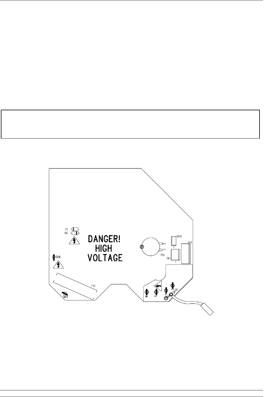
1.8 Wireless Repeater and WMA AC Power Connections
The Wireless Repeater and the WMA will contain a power module for the appropriate power supply
requested by the user. The power module is mounted the base half of the module with the wireless
module in the other half, the modules will be connected together by an interconnecting loom,
connected to SK1 on the power module and SK3A on the wireless module. The mains AC
connections are made to the power module connections SK6 and SK5, shown in the Figure below.
SK15, a flying lead, will be fitted to the appropriate tapping for the power supply that the customer has
indicated will be used. Fitting to the posts labelled W, X, Y and Z selects the correct voltage. This
should be checked for correct fitment before power is applied.
The Power cable and appropriate glands for the Wireless coordinator will need to be sourced locally,
according to site requirements.
Power should only be applied with the module fully assembled i.e. the base
and the cover connected together with the bolts supplied.
Cable glands used must be appropriate to the classification of the area.
Fig 14: Power module for Wireless Repeater and WMA.
P3 - Pakscan Master Station Technical Manual
16 of 134 Publication PUB059-002-00 Issue 05/12
1.9 WMA (Wireless Modbus Adapter) 24VDC Connections
The WMA may be powered from the Modbus device to which it is connected, assuming the device has
the appropriate DC supply available. Under this circumstance the interconnection cable between the
device and the WMA should contain 2 shielded pairs, one for power supply and one for the
communication signal. The distance between the Modbus device and the WMA should not exceed 10
meters in this case. The power connection on the WMA are pins 7 (+ve) and 8 (0volts) of SK3A.
1.10 WMA (Wireless Modbus Adapter) Modbus Connections
The WMA connects to a Modbus RTU device enabling a Modbus host to connect through the Pakscan
wireless system to the Modbus device. The connection between the Modbus device and the WMA
should be made using a shielded network cable with 1 twisted pair of wires. Suitable cable conforms
to the specification for RS-485 networks. This cable length will depend on the baud rate chosen for
communications.
The Communications cable and appropriate glands for the Wireless coordinator will need to be
sourced locally, according to site requirements. Connect the Communications cable as shown below,
SK3A is used on the WMA.
WIRELESS MODBUS
ADAPTOR
(WMA)
RS485
(B)
2RS485
(A)
1
Scr/
Gnd
3
Shield/Gnd
RS485 (B)
RS485 (A)
MODBUS DEVICE
Fig
15
:
PS721 to PS722 connections (Master station to Wireless Coordinator)

1. Mounting and Connecting the Master Station
Issue 05/12 Publication PUB059-002-00 17 of 134
1.11 Setting up the Wireless Repeater and WMA
The Wireless Repeater requires the PAN ID (Personal Area Network Identification number) and RF
Channel to be set up for the network to which it is attached. The WMA also requires these parameters
and its Modbus communication parameters to be set up. This is achieved using the Modbus interface
that is available on both modules.
The Modbus physical connections are detailed in the previous section ‘WMA (Wireless Modbus
Adapter) Modbus Connections’. For the purpose of configuration, these connections can be
temporary, for example, it may be more convenient to make the configuration changes in a workshop
before installation on site. For both devices it is likely that configuration is only required once,
therefore after installation there should be no need to access the Modbus connections again on the
Wireless repeater.
During configuration in a workshop environment, the 2 halves of the module can be separated, such
that the Wireless module is disconnected from its power supply module. The wireless module can
then be powered, separately, using a 24VDC source as described in the previous section ‘WMA
(Wireless Modbus Adapter) 24VDC Connections’.
For making configuration changes to the Repeater or WMA, there is a fixed Modbus address of 248.
The Wireless Repeater, ONLY requires the PAN ID and RF Channel to be set up, whereas the WMA
also requires the Modbus communication parameters (baud rate and parity) to be set up, as
appropriate for communicating to the Modbus slave device it is to be connected to. The Modbus slave
device address is not required to be set up within the WMA, as the WMA will automatically scan for
attached devices using the baud rate and parity set. Up to 10 slave Modbus devices can be
connected to the WMA, each device will require a unique Modbus address, within the range 201 to
247. The address must be unique for the host device to be able to access it. Within the master
station configuration pages, the Modbus addresses used for the devices fitted to the WMAs are
required to be selected. See section 7.5.17 master station configuration.
Changes to RF communication parameters will take place immediately. Changes to modbus
communication parameters will take effect after a power cycle and will apply to the Wireless Repeater
and WMA when configuring in the future as well as when the WMA communicates to its Modbus
device.
P3 - Pakscan Master Station Technical Manual
18 of 134 Publication PUB059-002-00 Issue 05/12
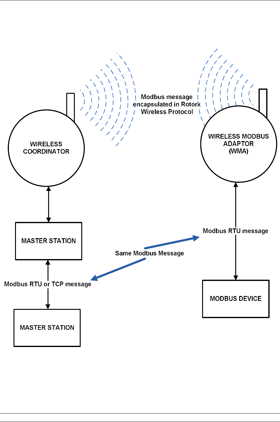
The principle of operation of the WMA is shown in the diagram below
Fig
16
:
Wireless Repeater and WMA database

1. Mounting and Connecting the Master Station
Issue 05/12 Publication PUB059-002-00 19 of 134
The following parameters can be configured when addressing the unit using the configuration Modbus
address of 248:
Modbus
Register
Modbus
Function code
Description
Range
Default
Value
R
ead /
Write?
100
03, 04, 06, 16
PAN ID
0000
–
FFFFhex
(0 – 65535)
DA15
hex
R/W
102
03, 04, 06, 16
RF Channel
16
–
25dec
(channel 16 to
Channel 25)
22
R/W
104
03, 04
03, 04, 06, 16
WMA
:
Lowest Modbus Address of
device (s) connected to the
WMA, if no device is found
this will default to 247
Repeater:
Address of the repeater,
required to be set up for
the device to appear in the
master station for status
info – must be unique in
the network
201
-
247
dec
301-315dec
247
301
R
O
R/W
200
03, 04, 06, 16
Modbus Baud rate
Value 1 to 5:
1–9600 / 2–19200
3–38400 / 4–57600
5-115200
1
(9600)
R/W
201
03, 04, 06, 16
RS485 Parity
Value 1 to 5:
1–None / 2-Odd
3-Even
1
(None)
R/W
The baud rate of communications between the WMA and the Device should be set to a value faster
that the host will communicate to the master station.
Fig
17
:
Wireless Repeater and WMA database

P3 - Pakscan Master Station Technical Manual
20 of 134 Publication PUB059-002-00 Issue 05/12
1.12 Front Panel LEDs
There are four Light Emitting Diodes (LEDs) on the front panel of the CPU module, in the bottom right-
hand corner. These are fitted to show if a unit is powered-up, which unit is in Primary or Standby mode
and whether there are any errors or alarms.
On power-up, there is a sequence of colour changes and flashes from the LEDs, which take almost a
minute to complete and confirms that all parts of the system are operating correctly:
The Status LED sequence is: off > amber > flashing green > steady green.
The Pri/Stdby LED sequence is: off > green > off > amber > steady green (amber for standby).
The Power LED sequence is: off > amber > green > green > steady green.
The Alarm LED sequence is: off > red > off > red > off.
The Status LED will show steady red if communications with the host is lost over Ethernet, or there is
a communications error between the master station and a field unit. The LED shows flashing green
only during the power-up sequence. The LED shows steady green to confirm that all applications are
running after power-up is completed.
The Pri/Stdby LED will show steady green if it is a singe unit or if it is the Primary unit of a hot standby
pair. The LED will show steady amber if it is the Standby unit in a hot standby pair.
The Power LED is off when there is no power and steady green when power is present. It only shows
amber during the power-up sequence.
The Alarm LED will show steady red if there are any alarm conditions in any field unit or the master
station. This alarm will not prevent operation of the master station.
Fig 18: CPU LEDs (Light Emitting Diodes)
2. The Field Current Loop Network
Issue 05/12 Publication PUB059-002-00 21 of 134
Port A
OUT = Term'l 5
IN = Term'l 4
Port B
IN = Term'l 1
OUT = Term'l 2
Up to 240 actuators
per loop
Current loop
- up to 20 km
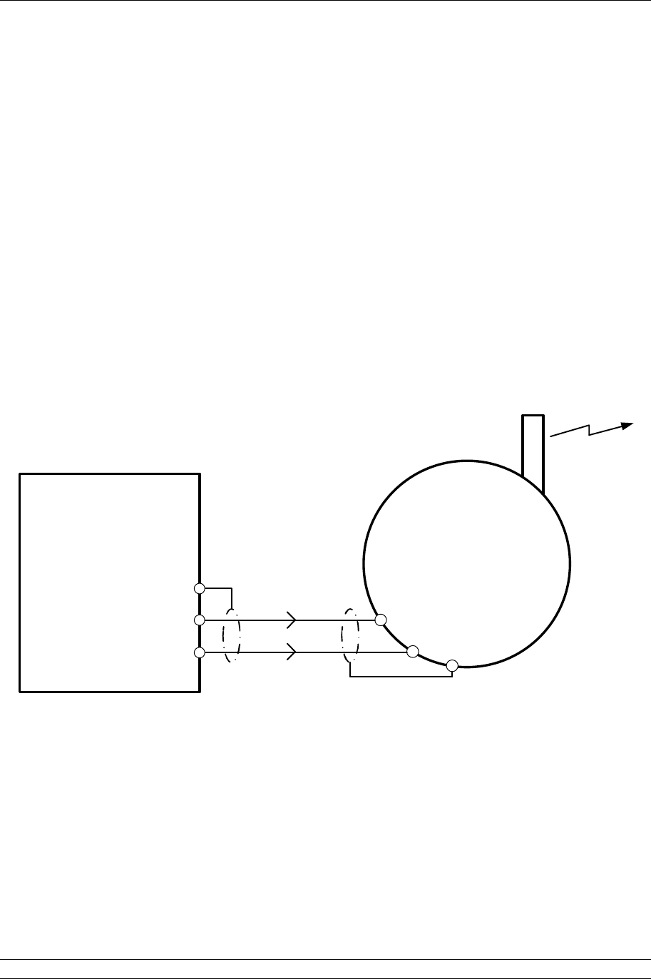
2. THE FIELD CURRENT LOOP NETWORK
The Pakscan current loop field network must be correctly cabled and connected to the master station.
The values of the field loop resistance and capacitance must be known to determine the loop speed
that can be used. If these are not known then the LOWEST loop speed must be set in each actuator
and the master station to ensure good field network connectivity.
Fig 19: Pakscan P3 Wired Network

P3 - Pakscan Master Station Technical Manual
22 of 134 Publication PUB059-002-00 Issue 05/12
2.1 Loop Checks
The most common errors in installing the system occur on the field wiring.
Loop Continuity
With all the field units connected, but none of them powered up, check the continuity of the 2
cores of the Pakscan loop cable. Measure and record the resistance of each core. These
measurements will be useful as they can be compared with future measurements to determine
if cable resistance has changed significantly or not, this may help identify a cable fault. Cable
resistance (R) is the sum of the resistance of both cores.
Screen Continuity
Screen continuity must be continuous between each end of the loop. Ensure the screen is either
connected to a signal earth bar at only one point or to terminals on the loop driver plug; pin 3
connects directly to the enclosure earth and pin 6 connects to the enclosure earth via an
internal capacitor, preventing an earth loop. Both screens must be connected to the terminals
provided on the loop driver, so as to ensure the product meets the European Directive on EMC.
Cable Capacitance
The capacitance (C) between the cores of the cable is critical to system performance. Too high
a capacitance for the selected loop baud rate will result in poor communications, or even
communication failure. If a suitable meter is available, measure and record the capacitance
between the cable cores.
Maximum Loop Speed
The cable resistance must not exceed 500 Ohms (250 Ohms per core) and the total
capacitance must not exceed the maximum value for each communication speed. In addition to
cable capacitance, each field unit adds a small amount of capacitance to the loop which must
also be considered when determining maximum loop speed. Use the measured resistance and
capacitance values from the above tests to determine which loop speed should be used.
Baud Rate R max (ohms) C max (F)
110 500 4.5
300 500 2.1
600 500 1.54
1200 500 0.6
2400 500 0.3
Each field unit will add a capacitance of 2.2nF
The C max figure given is the maximum value for the network capacitance
including the field unit capacitance.
Test Equipment
A good quality multimeter with capacitance test facility is adequate for testing loop resistance
and capacitance. Under no circumstances should any high voltage test equipment be used
such as insulation Megga testers when any part of the cable loop is connected to either the
master station or actuators. The high test voltages generated by such equipment may damage
the Pakscan components.
2. The Field Current Loop Network
Issue 05/12 Publication PUB059-002-00 23 of 134
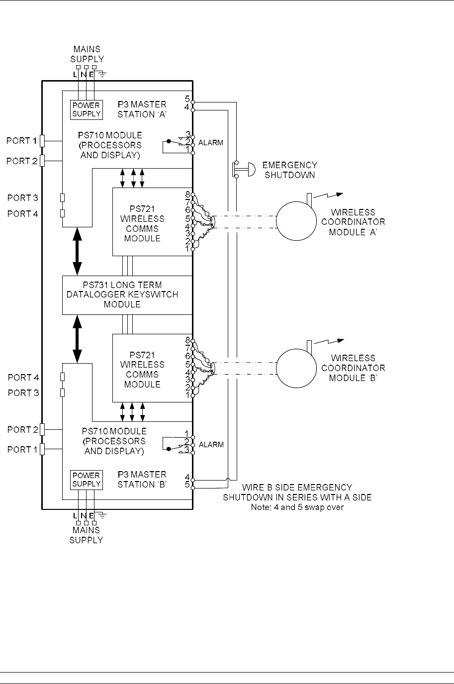
2.2 Connecting Up
Once the checks are complete, connect the Loop Cables to the PS730 Key switch module on a hot
standby system or the PS720 Current Loop module on a single system. The Pakscan loop should
look like figure 15. Check the loop wiring complies with this drawing and then proceed to Section 8.1
for commissioning instructions.
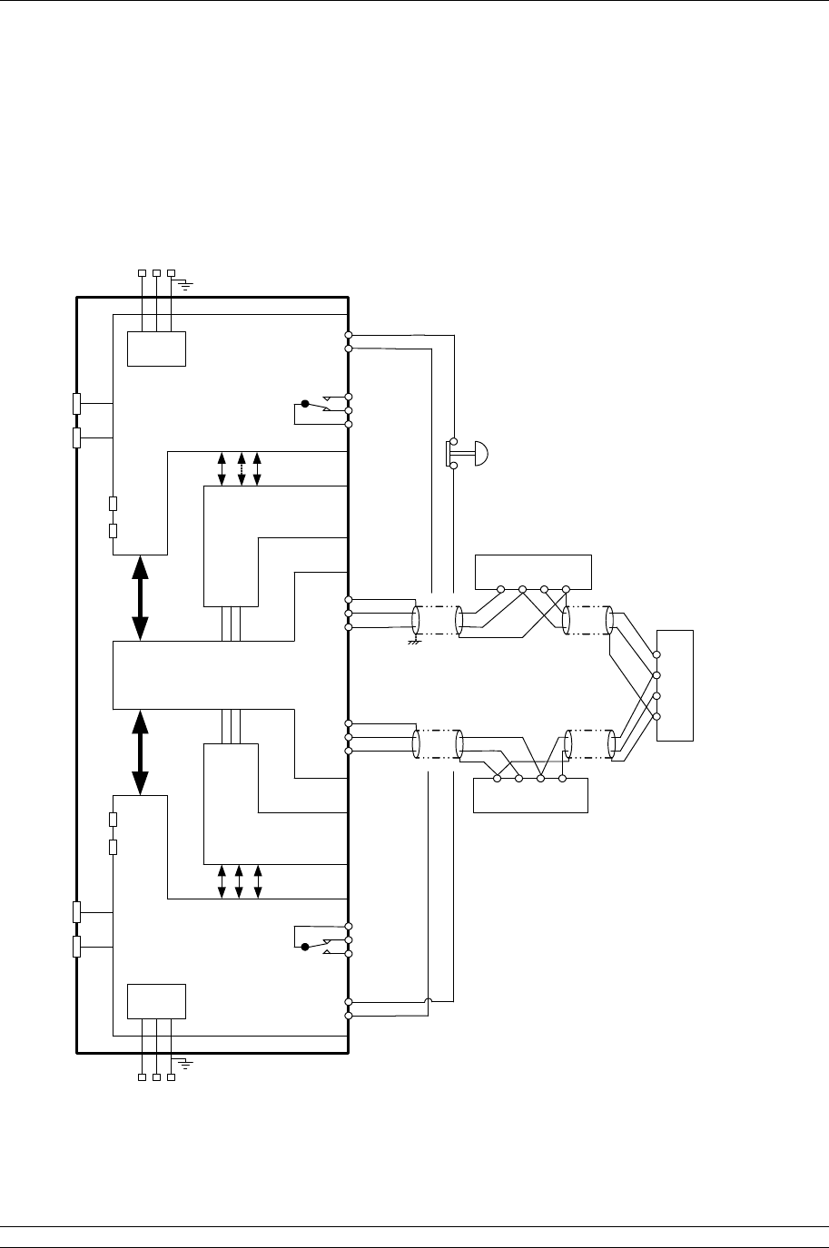
Note: If there is no hard-wired ESD requirement a shorting link must be fitted across pin 4 and
5 on both side A and side B of the PS710 modules
Fig
20
:
Pakscan P3 Current Wired Loop
System Block Diagram (hot standby master
station)
POWER
SUPPLY
POWER
SUPPLY
MAINS
SUPPLY
MAINS
SUPPLY
L N E
L N E
PORT 1
PORT 3
PORT 2
PORT 4
PORT 1
PORT 2
PORT 3
PORT 4
1
2
3
4
5
4
5
6
1
2
3
1
2
3
4
5
SCR
Actuator Terminals
Actuator Terminals
Actuator Terminals
B C A
SCRA C B
A C B SCR
ALARM
EMERGENCY
SHUTDOWN
WIRE A SIDE EMERGENCY
SHUTDOWN IN SERIES WITH B SIDE
Note: 4 and 5 swap over
ALARM
Screen
Screen
Port A OUT
Port A IN
Port B OUT
Port A IN
PS710 MODULE
(PROCESSORS
AND DISPLAY)
PS710 MODULE
(PROCESSORS
AND DISPLAY)
P3 MASTER
STATION ‘A’
P3 MASTER
STATION ‘B’
PS720 MODULE
(CURRENT LOOP
CONTROLLER)
PS720 MODULE
(CURRENT LOOP
CONTROLLER)
PS730
KEY SWITCH
MODULE
SIGNAL EARTH BAR
If there is a signal earth bar,
connect the screen on one side only
to the bar.
P3 - Pakscan Master Station Technical Manual
24 of 134 Publication PUB059-002-00 Issue 05/12
POWER
SUPPLY
MAINS
SUPPLY
L N E
PORT 1
PORT 2
PORT 3
PORT 4
1
2
3
4
5
4
5
6
1
2
3
SCR
Actuator Terminals
Actuator Terminals
Actuator Terminals
B C A
SCR
AC B
ACB SCR
ALARM
EMERGENCY
SHUTDOWN
Screen
Screen
Port A OUT
Port A IN
Port B OUT
Port A IN
PS710 MODULE
(PROCESSORS
AND DISPLAY)
P3 MASTER
STATION ‘A’
PS720 MODULE
(CURRENT LOOP
CONTROLLER)
SIGNAL EARTH BAR
If there is a signal earth bar,
connect the screen on one side only
to the bar.
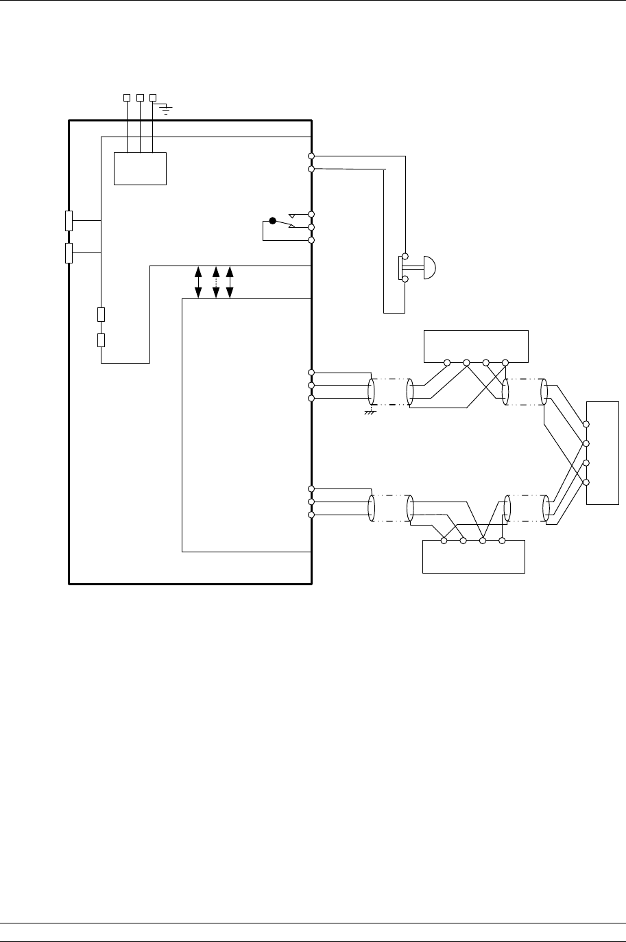
Fig 21: Pakscan P3 Current Wired Loop System Block Diagram (single master station)
Note: If there is no hard-wired ESD requirement a shorting link must be fitted across pin 4 and
5 of the PS710 module

3. The Field Wireless Network
Issue 05/12 Publication PUB059-002-00 25 of 134
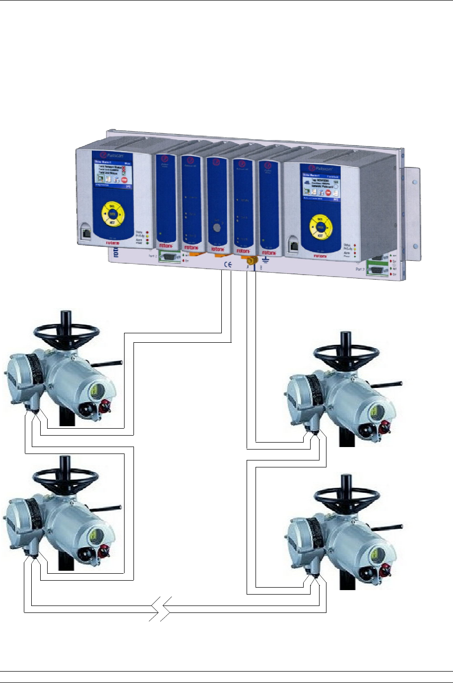
3. THE FIELD WIRELESS NETWORK
A Pakscan wireless network will contain a master station with a PS721 module fitted to its back plane
(2 for hot standby). Each of these will connect to a PS722 Wireless coordinator module. The
coordinator module is the device that controls and organises the wireless network. For an actuator to
be connected on the network it must have a wireless actuator module. The IQ and IQT range of
actuators fully integrate into the wireless system. Other devices can be integrated into the system
using a Wireless to Modbus adaptor (WMA). The WMA can be attached to any device that has a
Modbus interface on it. The host then uses the master station and the wireless network as a transport
layer only to send Modbus messages that are directed to a Modbus device.
A network may also require a number of repeaters to overcome wireless dead spots or to ensure a
redundant path to all devices.
Fig 22: A typical P3 wireless network
Up to 60 devices can be connected in a wireless network. The distances between each node in the
network is recommended to be no more than:
Indoors: 30 metres
Outside: 100 metres
In practice, it has been found that these distances can be extended, but a site survey is required to
confirm this. Each device is able to route messages onto the next device. By this method, the range
of the network is increased. It is recommended to have no more than 7 ‘hops’ from the master station
to the final device. A ‘hop’ is where a message routes through a wireless device to get to the
destination device.

P3 - Pakscan Master Station Technical Manual
26 of 134 Publication PUB059-002-00 Issue 05/12
3.1 Wireless Site Survey
The first step in setting up a wireless network will be a Wireless Site Survey, which would be
performed by Rotork Personnel. This will establish the suitability of the site for a wireless network. The
survey will establish the levels of background wireless signals within the spectrum of the 2.4 GHz
band used for the P3 wireless network and also the potential strength of the wireless signals between
the actuator and coordinator locations. This will aid in positioning the coordinator and in deciding upon
the need for repeaters.
As a result of the survey, one or more, channels within the band will be found to be suitable for the
network. All devices on the network will be shipped with a default channel set.
3.2 Wireless Specification
Network Based on: IEEE 82.15.4, DSSS (Direct Sequence Spread Spectrum).
Maximum Wireless devices: 60.
Frequency: 2.4GHz band.
Operating Range: 30m indoors, 100m outside.
Network Structure: Mesh.
Channels available: 16.
Security: AES and anti-spoofing.
Power: 10mW default, potential for 100mW if the location allows.
3.3 Connecting Up
The IQ and IQT actuators fitted with a wireless module will only require mains power connections and
the appropriate glands for the environment to be connected to them. Where a WMA is supplied,
power is required to be provided by the user and the user must also provide the necessary cable and
glands between the WMA and the device to which it is attached. A repeater also only requires a
power cable and glands supplied by the user. The power required for the Repeater and WMA will be
indicated on the serial label.
Figure 17 shows the master station block diagram.
The site survey will have indicated the appropriate position to locate the coordinator(s) and any
repeaters. Once all the equipment is in place, the user can then proceed to Section 8.2 for
commissioning instructions.
3. The Field Wireless Network
Issue 05/12 Publication PUB059-002-00 27 of 134
Fig 23: Pakscan P3 Wireless network Block Diagram (hot standby master station)
Note: If there is no hard-wired ESD requirement a shorting link must be fitted across pin 4 and
5 on both side A and side B of the PS710 modules.

P3 - Pakscan Master Station Technical Manual
28 of 134 Publication PUB059-002-00 Issue 05/12
(This page is intentionally blank)
4. Configuring Serial Communications
Issue 05/12 Publication PUB059-002-00 29 of 134
Port 1
Port 2
P
3
P
3
PS720
IIE Loop
Standby
Port A
Port B
P
3
PS720
IIE Loop
Standby
Port A
Port B
P
3
PS700
CPU/PSU
Port 1
Port 2
Option 1
Option 2
Switch
A B
CЄ
Option 2
Option 1
CPU/PSU
Not Cross
Connected
Cross
Connected
Port Terminations
Off
On
On
Off
1
2
Port 1
Port 2
RS232
RS485
Port Terminations
Off
On
On
Off
1
2
Port 1
Port 2
Port 1
Port 2
Port 1
Port 2
A
Only
B
Only
Port 1
Port 1
Port 2
Port 2
rotork
rotork
rotork
rotork
rotork
RS232
RS485
4. CONFIGURING SERIAL COMMUNICATIONS
The Pakscan 3 CPU module has two serial ports. Each of these is configurable for RS-232 or RS-485.
Most hot standby systems will probably require two RS-485 connections in a seamless redundant
configuration. Single systems may use RS-232 or RS-485.
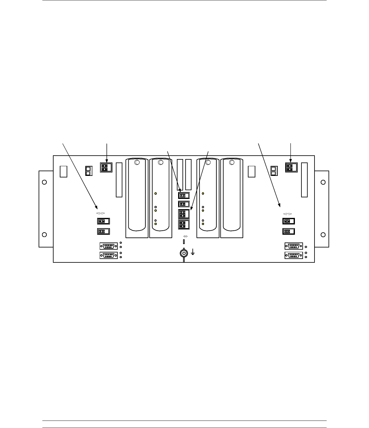
4.1 Setting Port 1 and 2 for RS-232 or RS-485
The chassis has DIP switches behind the PS710 CPU module for setting the type of serial port that is
presented at the port connectors.
Fig 24: Pakscan P3 Chassis, CPU and Key Switch modules removed
The switches on the backplane behind the PS710 CPU Module are used to set Port 1 and Port 2
parameters.
Select
Function
Select RS-485
Termination Select RS-
485
Cross
Connection
CPU Feedback
for Cross
Connection
Select
Function Select RS-485
Termination

P3 - Pakscan Master Station Technical Manual
30 of 134 Publication PUB059-002-00 Issue 05/12
Port Function
Two DIP switches allow each port to be selected between RS-
232 and RS-485. For RS-485 slide the appropriate Port
switches to the right, for RS-232 they should be on the left.
Each of the two ports may be set independently.
Fig 25: Port Function Switches shown in RS-232 position
RS-485 Termination Resistors
Two DIP switches are used to connect end-of-line termination and biasing resistors to the RS-485
highway. All RS-485 network highways must be terminated at both ends of the highway, in this case,
at the host controller and at the master station. Only RS-485 highways need termination and biasing
resistors. If a CPU port is configured for RS-232, it must never be terminated. Each port can be
terminated independently.
Each CPU module serial port sits on an independent highway and should be terminated
independently. So, if ports 1 & 2 on a CPU module are both being used for redundant RS-485
communications to a Host controller, then each port may need to be terminated and biased.
However, where more than one CPU Module sits on the same RS-485 highway, then only the one
furthest from the host controller needs the biasing and termination resistors to be enabled.
Fig 26: Port Termination Switches shown in Off position
RS-232 RS-485
Port 1
Port 2
1k
1k
+5V
Gnd
120
Data +
Data -
Off
On
Off
On
4. Configuring Serial Communications
Issue 05/12 Publication PUB059-002-00 31 of 134
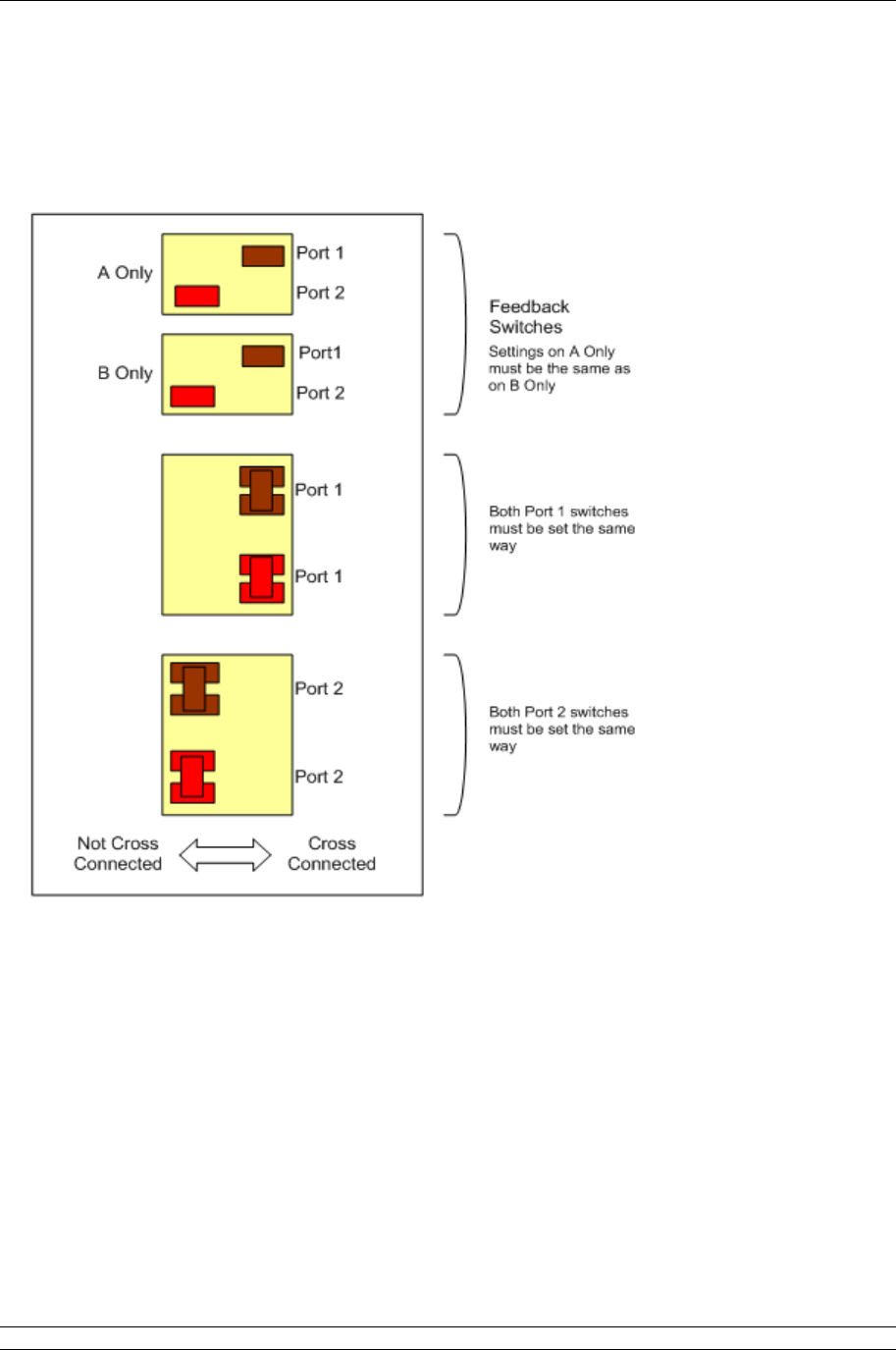
Cross Connection switches
The cross connection switches, found on the backplane behind the PS710 CPU Module, are used to
cross connect the serial RS-485 connections. They are only applicable for a hot standby system and
should ONLY be set as cross connected for a port that has been selected as RS-485.
Fig 27: Cross connection switch settings on the backplane behind the Switch Module
The switches are shown in the Factory Default positions (Hot Standby).
Port 1 is set to Cross-Connected for RS-485 Serial communications. Port 2 is set to Not Cross-
Connected for RS-232 Serial Communications.
The feedback switch positions must reflect the Cross-Connection settings for Port 1 and Port 2.
These switches are used, by the master station CPU, to indicate to the user (via the HMI or web
pages) the position of the cross-connect switches.
P3 - Pakscan Master Station Technical Manual
32 of 134 Publication PUB059-002-00 Issue 05/12
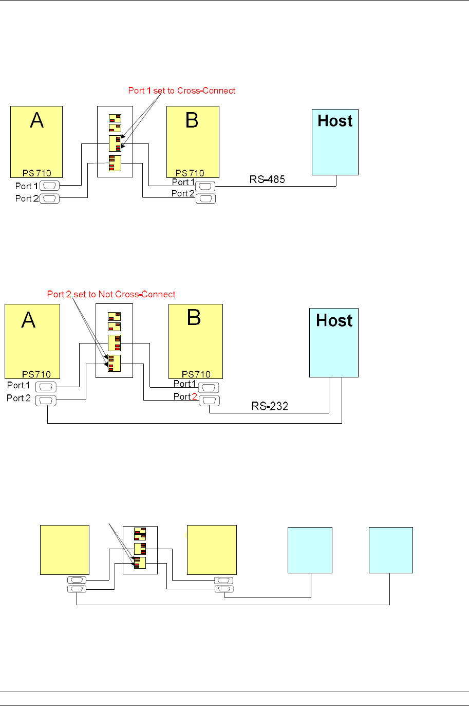
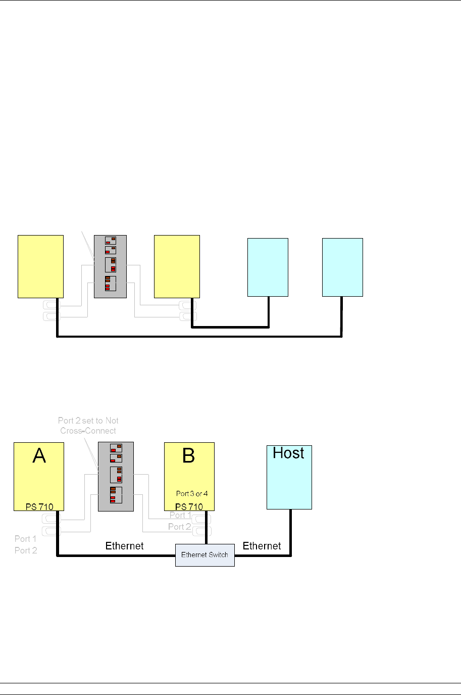
Typical Serial Host connections to the P3 master station and appropriate switch settings:
Hot Standby RS-485 communications
Communications between the Host and the master stations uses the Modbus protocol. Because the
Master A is cross-connected to Master B, they both share the same Modbus address. The standby
action must then be set to passive. Thus, the host can have two-way communications with the Primary
(Main ) module and the Standby module will only listen to the messages.
Hot Standby RS-232 Communications
With RS-232, communications between the Host and Hot Standby master station must be point-to-
point. Multi-drop connection is not allowed, so separate cables must be run from the Host to each side
of the master station. Also, the Cross-Connect switch must be set to Not Cross-Connect. The standby
action must be set to active, so that the Host has full communications with Master A and Master B.
Note: only actuator commands sent to the Primary CPU Module will be actioned.
Hot Standby dual Host RS-232 or RS-485 communications
Fully dual-redundant system. Port 2 set to RS-232 or RS-485 to match Host communication
Fig 28: Hot Standby Serial Communications
A B
P o rt 1
P o rt 2
P S 7 1 0 P S 7 1 0
P o rt 1
P o r t 2
H o s tH o s t
1 2
R S -2 3 2 o r
R S -4 8 5
P o r t 2 s e t to N o t C ro s s -C o n ne c t
5. Configuring Ethernet Communications
Issue 05/12 Publication PUB059-002-00 33 of 134
5. CONFIGURING ETHERNET COMMUNICATIONS
Pakscan 3 master stations come complete with two Ethernet ports for connection to host systems. A
third Ethernet port is also available for connection to a computer for configuration purposes. The
master station is ready to use with Ethernet and Modbus TCP protocol for the host to access data and
control the actuators on the field network. The IP address is factory set to the default value and can be
changed during set up of the master station.
The Pakscan master station defaults to the same IP address on both ports, and can use the same
address on the A and B master stations. It is possible to change the IP address on either master
station, but ports 3 and 4 of each CPU Module always have the same address.
Hot Standby Ethernet communications
A B
Port 1
Port 2
PS 710 Port 1
Port 2
HostHost
1 2
PS 710
Port 3 or 4 Port 3 or 4
Port 2 set to Not
Cross-Connect
Ethernet Ethernet
Ethernet comms between Hosts and master station are made using Port 3 or Port 4. The Cross-
Connect switches can be in either position, or set appropriately for any additional serial comms. In this
case, with two Hosts, Standby must be set to Active. The IP address of Master A and Master B can
be set to be the same or different, with Standby Active.
Where an Ethernet switch is used to connect a Host to the hot standby master station and the IP
address is set the same for Master A and B, then Standby must be set to Passive.
Fig 29: Hot Standby Ethernet Communications
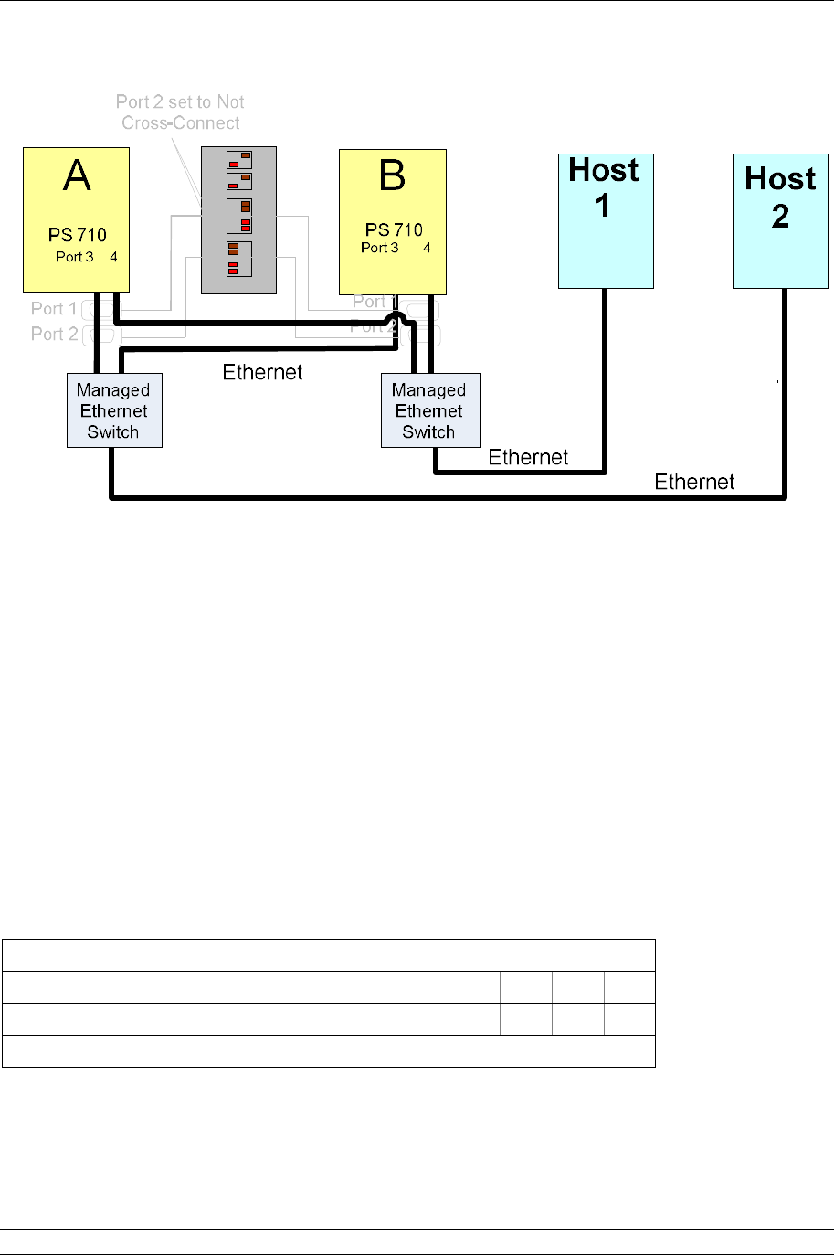
Hot Standby Redundant Host, Redundant Ethernet communications
P3 - Pakscan Master Station Technical Manual
34 of 134 Publication PUB059-002-00 Issue 05/12
Fig 30: Hot Standby, Dual Redundant Ethernet Communications
For full Ethernet communications redundancy, use two Hosts and two managed Ethernet switches.
Managed Ethernet switches with rapid spanning tree protocol are required. This type of switch is able
to prevent Ethernet Storms, where messages are re-circulated continuously.
Ethernet communications between Hosts and master station are made using Port 3 and Port 4. In this
case, with two Hosts, Standby must be set to Passive. The IP addresses of Master A and Master B
can be set to be the same with Standby Passive, or different, with Standby Active.
The Pakscan P3 master station defaults to the same IP address on all ports. It is possible to change
the IP address for Master A and Master B independently, but all ports for each master will have the
same address. In a hot standby system, if the Copy IP Settings option is selected, both sides of the
master station will have the same IP address.
5.1 Default Ethernet Settings
The default Ethernet parameters set in each Pakscan 3 CPU Module are given below:
DHCP Static
Default IP address 10
200
1
1
Default Subnet mask 255
255
255
0
Standby Action Passive
Note: changes to the IP address, Subnet Mask or clock settings will cause a re-boot of the CPU
module.

5. Configuring Ethernet Communications
Issue 05/12 Publication PUB059-002-00 35 of 134
5.2 Ethernet Security
When connecting the master station to an Ethernet network, care should be taken to consider security
of the master station.
There are a number of Ethernet services available in the master station and, where appropriate, the
user should ensure that the Ethernet infrastructure is able to protect the master station from unwanted
access to a service.
Transmission Control Protocol (TCP) and Internet Protocol (IP) are the core protocols utilised in Local
Area Networks (LANs) and computer networking. Within these networks a ‘port’ is an endpoint to a
logical connection – not to be confused with the physical port!
The port number in this case refers to the type of port. For example, port 80 is used for HTTP web
page traffic.
The ports that are available at the master station are:
Port description Port number
Telnet 23
FTP 21
HTTP 80
HTTPS 443
Modbus/TCP 502, 50003, 50004, 50005,
50006, 50007, 50008 and 50009
Ethernet products, like routers, can prevent other Ethernet equipment on the same LAN from
accessing certain services in the master station. If web page access were not required, the most
secure set up would be to prevent all but Modbus traffic entering the master station.

P3 - Pakscan Master Station Technical Manual
36 of 134 Publication PUB059-002-00 Issue 05/12
(This page is intentionally blank)
6. Setting Up the Master Station by the Keypad
Issue 05/12 Publication PUB059-002-00 37 of 134
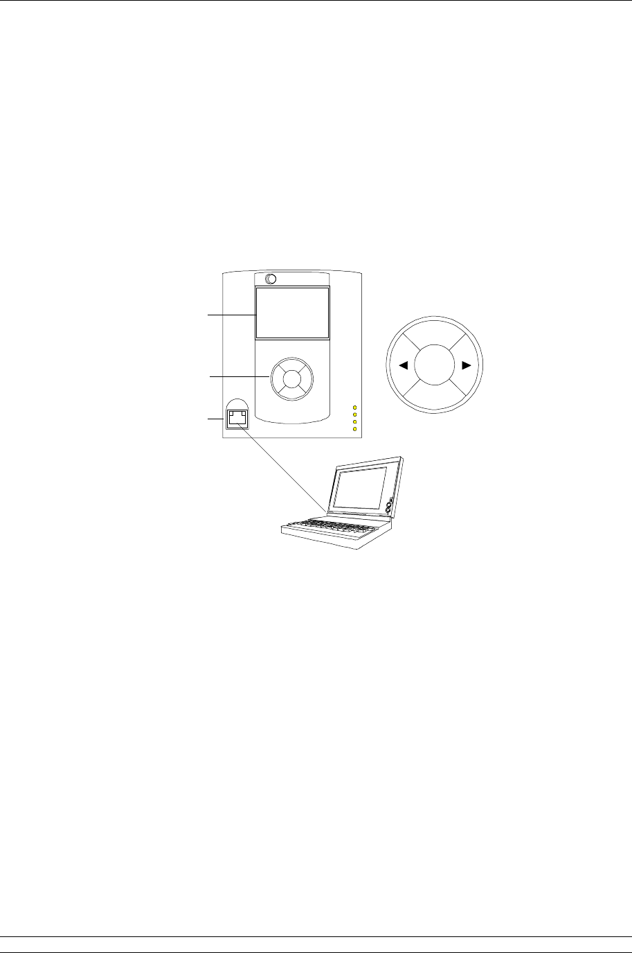
6. SETTING UP THE MASTER STATION BY THE KEYPAD
The Pakscan 3 master station CPU module has a full colour display and 5 button input pad. All the
settings for the performance of the master station, the Option module fitted and the Field Network can
be made using these facilities. The keypad and screen also allows every connected actuator to be
interrogated and its status monitored. Finally, the actuators and valves can be moved using these
facilities.
Alternatively, a computer with an Internet browser facility can be used with the internal web server
pages. These pages allow the whole system to be set up and modified. In addition, they allow the
connected actuators to be viewed and controlled.
Fig 31: Pakscan P3 Main module connection to laptop and keypad detail
6.1 Using the Keypad
The keypad controls the movement through the display screens and the movement within each
screen, as well as the ability to input data or requests.
(Left) and (Right) arrow keys Allow active items within a page display to be highlighted.
If the item is selected and a numeric input is needed,
then these keys increase or decrease the number.
ENTER Selects a highlighted element on the screen or completes
the entry of information.
BACK and NEXT BACK moves up one level in the menu of the displays,
returning to the previous screen viewed. NEXT only
functions if there is more data to show than fits on the
screen. When there is additional data, a small arrow is
shown on the right side of the screen. It points down ()
for NEXT and up () for BACK to operate.
Ethernet cable
Display
Keypad
Ethernet
Set up
Port
Keypad Detail
Status
rotork
Pri/Stby
Power
Alarm
PS710
Pakscan
P
3
BACK
NEXT
ENTER
P3 - Pakscan Master Station Technical Manual
38 of 134 Publication PUB059-002-00 Issue 05/12
BACK
NEXT
ENTER
BACK
NEXT
ENTER
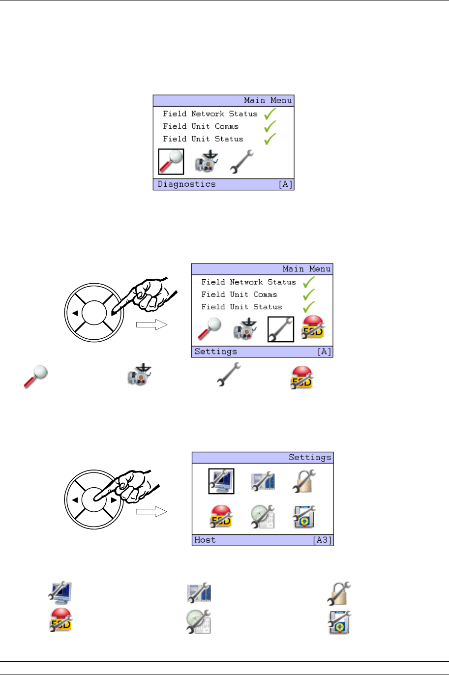
6.2 The Screen Display
The opening, or top screen display shows the network status and three icons (four icons, if keypad
ESD is enabled – see below).
Menu Section
Network Information
Current Status
Selected Icon Highlighted
Selected Icon Function
Menu Location
The Diagnostics icon (Magnifying Glass) will have a black square around it. The position of the square
indicates the part of the menu that will be accessed if the ENTER key is pressed. The highlighted icon
can be changed by pressing the arrow buttons ( or ) to scroll round them. The bottom bar shows
the selected function as a text message.
Diagnostics Menus Field Unit Menus Settings Menus ESD control - only visible when
“Keypad ESD” is enabled
Highlight the Spanner icon for ‘Settings’; then press ENTER. The menu location changes to A3 and
the ‘Settings’ menu screen appears with the ‘Host’ icon selected.
This screen also contains the icons used for access to all the other setting menus.
Host Option Module Security
ESD Date/Time M/S

6. Setting Up the Master Station by the Keypad
Issue 05/12 Publication PUB059-002-00 39 of 134
BACK
NEXT
ENTER
BACK
NEXT
ENTER
BACK
NEXT
ENTER
BACK
NEXT
ENTER
BACK
NEXT
ENTER
6.3 Setting the Current Loop Option Module Parameters
On the ‘Settings’ menu, select the Option Module Icon by pressing the right arrow key () followed by
the ENTER key.
The Option choice screen appears where the module to be set can be selected. Firstly we need to
ensure that the field units are correctly assigned to the field network chosen. The selection box by the
‘Option 1’ text should be highlighted by pressing the right arrow key twice ().
Pressing ENTER enables changes to be made using the left () or right () arrow key, press the
ENTER key to make a change to the value. This box will increment in steps of 60. In a wired only
network all available field units should be allocated to the Pakscan 2 module. Once the number is
correct, press ENTER once more
To make changes to the Pakscan 2 Current Loop module settings, highlight Option 2 by using the left
() or right () arrow key.
P3 - Pakscan Master Station Technical Manual
40 of 134 Publication PUB059-002-00 Issue 05/12
BACK
NEXT
ENTER
BACK
NEXT
ENTER
BACK
NEXT
ENTER
BACK
NEXT
ENTER
BACK
NEXT
ENTER
BACK
NEXT
ENTER
BACK
NEXT
ENTER
BACK
NEXT
ENTER
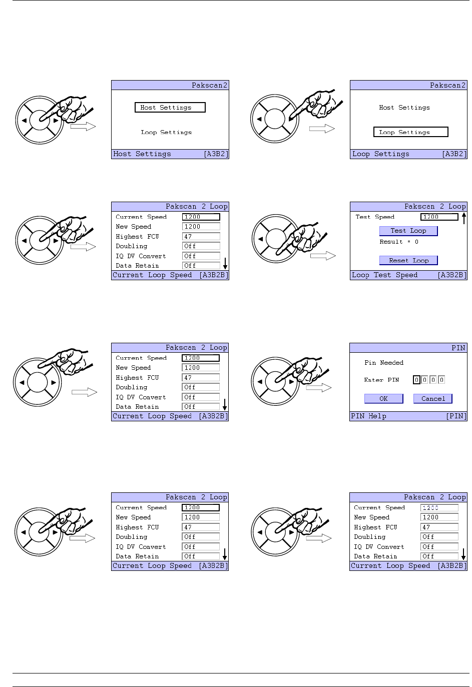
Pressing ENTER brings the next choice for the setting. This time select ‘Loop Settings’ by once more
using the right arrow key ().
The Loop Settings screen is split over two pages, as indicated by the small arrow () on the right side
of the screen, so the NEXT and BACK buttons are used to jump between the two.
Once a setting box is highlighted, by using the left () or right () arrow key, press the ENTER key to
make a change to the value. This will make the security screen appear for the PIN number entry. The
default value for the system security requires a PIN to be entered before any settings can be changed.
This setting can be altered from the Security Setting menu.
The default PIN number is 0000. To enter a PIN, or accept the number, press ENTER and the first
digit will flash. The value can be changed by using the left or right arrow keys ( or ). Once the
number is correct, press ENTER once more. When all 4 digits of the PIN are entered correctly, select
the OK button with the arrow keys ( or ).
Press ENTER and the screen will return to the settings screen and the Current Speed will be
highlighted. Press ENTER once more to select this parameter and the current value begins to flash.
6. Setting Up the Master Station by the Keypad
Issue 05/12 Publication PUB059-002-00 41 of 134
BACK
NEXT
ENTER
BACK
NEXT
ENTER
BACK
NEXT
ENTER
BACK
NEXT
ENTER
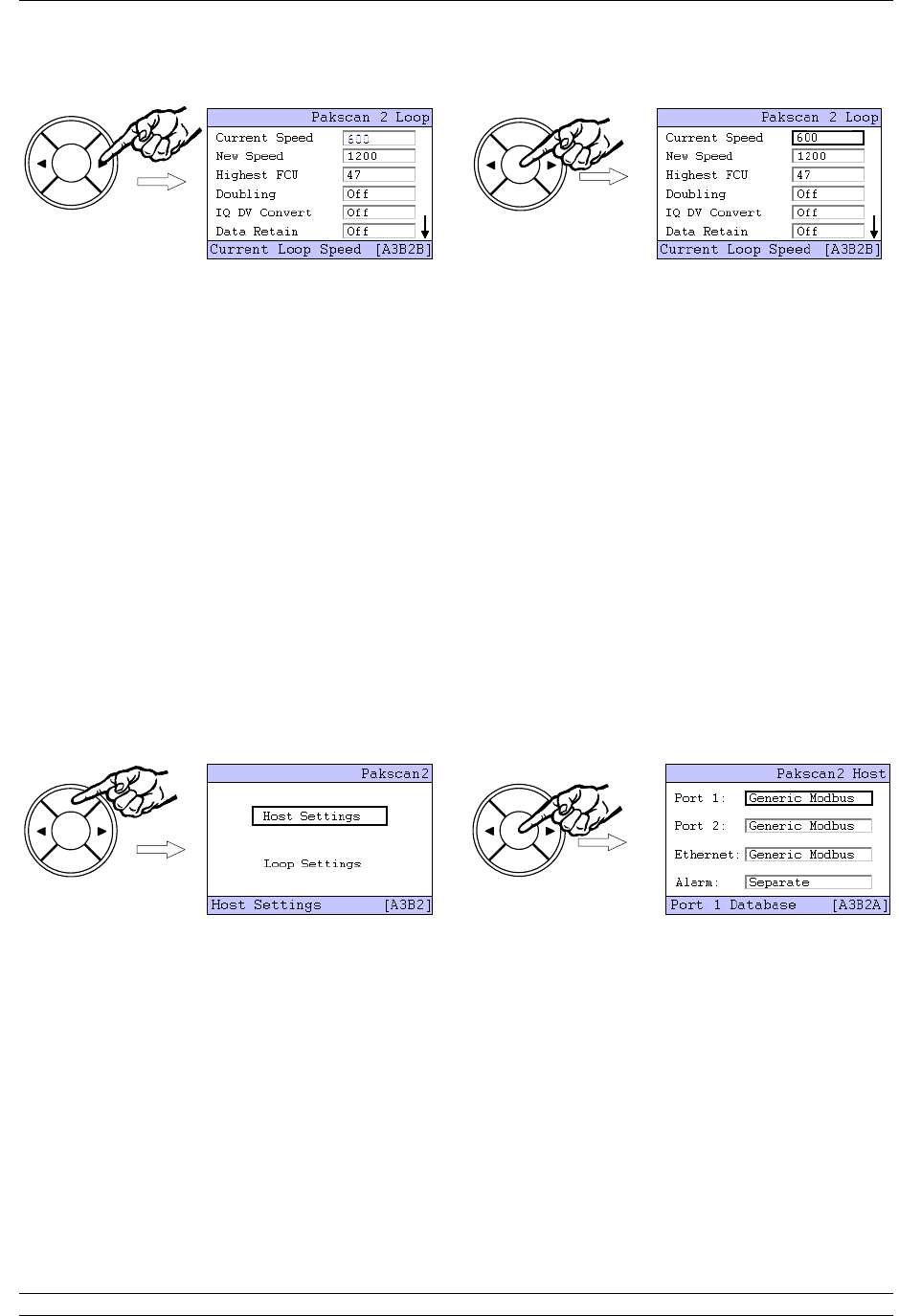
Use the arrow keys ( or ) to change the value shown until the desired figure appears, then press
ENTER and the new value will be set. The arrow keys can be used to navigate to other settings, and
the NEXT button goes to the Loop Test screen and Loop Reset function.
Set the loop performance parameters in accordance with the data recorded earlier. Make sure
the loop speed is compatible with the setting for the loop capacitance.
Set the highest field unit address parameter equal to the actual highest address.
Doubling can be set to ‘On’ if the loop performance is not fast enough. It has the effect of
halving the time to collect data from the field units. This feature will only operate if the loop is
functioning correctly with “loopbacks off”.
IQ DV Convert should be set to ‘On’ if analogue position control is being used on the IQ / IQT
actuators on the network.
Data Retain set to ‘Off’ clears all the field unit data if communication is lost. Some host
systems want the data to be retained, in which case set the parameter to ‘On’.
Once the parameters are all set, leave this part of the setting menu to ensure the new values are
loaded. Use the BACK button to return to the Host Settings page, and then ENTER to select the Host
Settings menu.
Make alterations to the host protocol settings and Alarm linkage, if required, in a similar manner to
altering the loop performance parameters described earlier. The PIN will need to be entered if no keys
are operated for approximately 5 minutes from the last PIN entry. Where the two serial ports are being
used by the same host system it is advisable to ‘Link’ the alarms so that both ports always report
exactly the same alarm data.

P3 - Pakscan Master Station Technical Manual
42 of 134 Publication PUB059-002-00 Issue 05/12
BACK
NEXT
ENTER
When the settings are as required, use the BACK key to return to the top Settings menu.
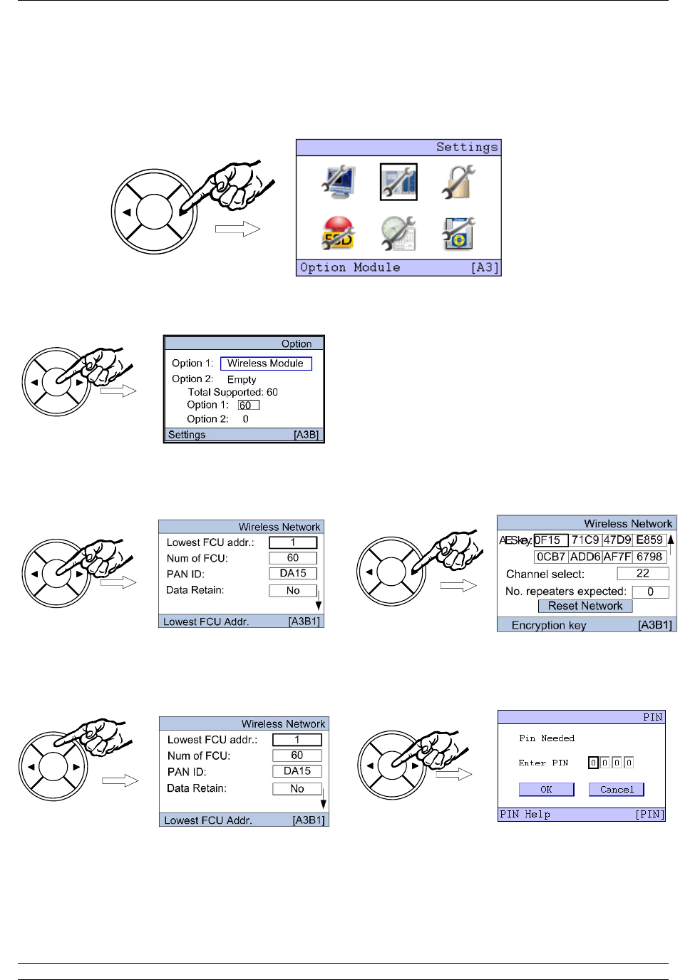
6. Setting Up the Master Station by the Keypad
Issue 05/12 Publication PUB059-002-00 43 of 134
BACK
NEXT
ENTER
BACK
NEXT
ENTER
BACK
NEXT
ENTER
BACK
NEXT
ENTER
BACK
NEXT
ENTER
BACK
NEXT
ENTER
6.4 Setting the Wireless Option Module Parameters
On the ‘Settings’ menu, select the Option Module Icon by pressing the right arrow key () followed by
the ENTER key.
The Option choice screen appears where the module to be set can be selected. The Pakscan
Wireless is always in the Option 1 slot and this is highlighted as the page is entered.
The Wireless network Settings screen is split over two pages, as indicated by the small arrow () on
the right side of the screen, so the NEXT and BACK buttons are used to jump between the two.
Once a setting box is highlighted, by using the left () or right () arrow key, press the ENTER key to
make a change to the value. This will make the security screen appear for the PIN number entry. The
default value for the system security requires a PIN to be entered before any settings can be changed.
This setting can be altered from the Security Setting menu.
The default PIN number is 0000. To enter a PIN, or accept the number, press ENTER and the first
digit will flash. The value can be changed by using the left or right arrow keys ( or ). Once the
number is correct, press ENTER once more. When all 4 digits of the PIN are entered correctly, select
the OK button with the arrow keys ( or ).
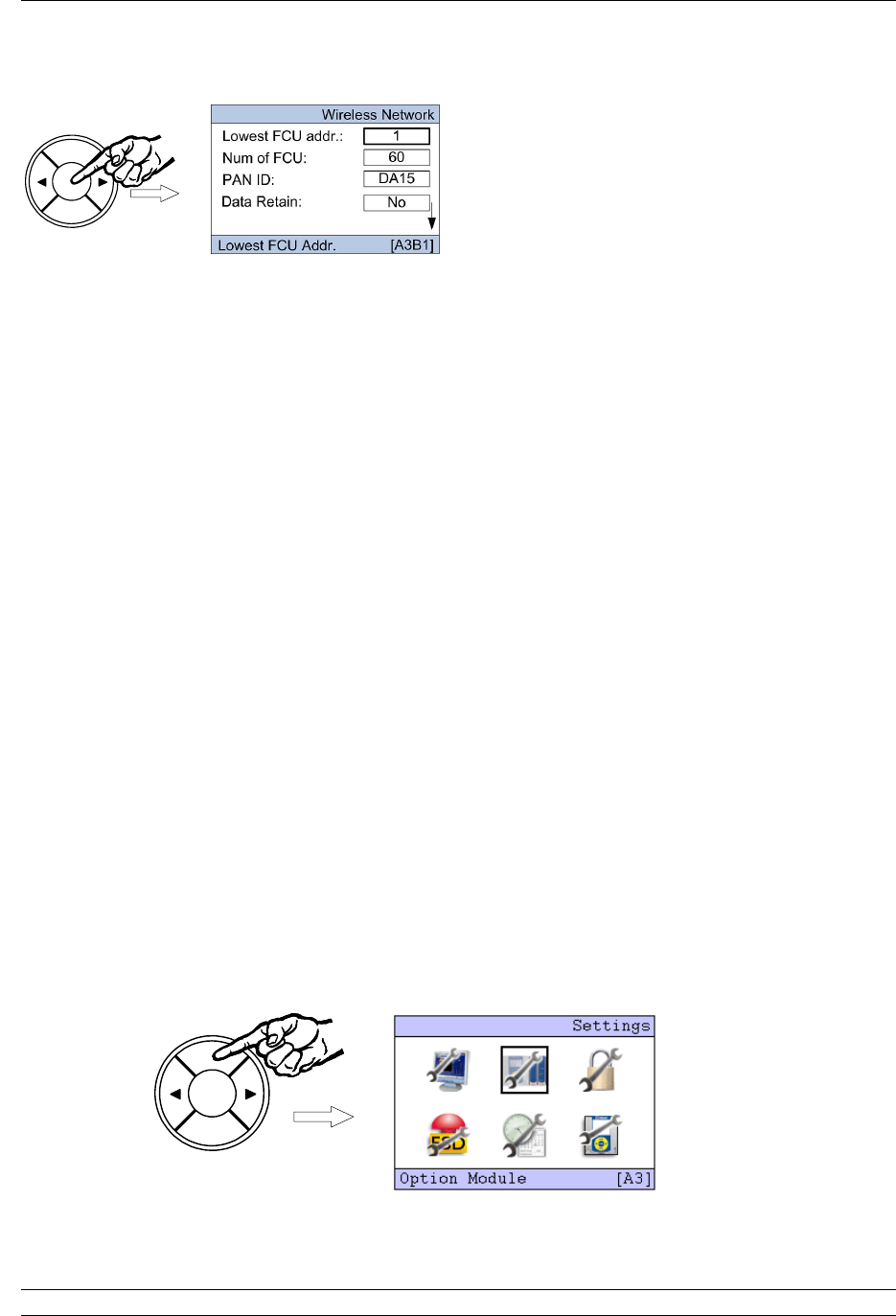
P3 - Pakscan Master Station Technical Manual
44 of 134 Publication PUB059-002-00 Issue 05/12
BACK
NEXT
ENTER
BACK
NEXT
ENTER
Press ENTER and the screen will return to the settings screen and the Lowest FCU addr. will be
highlighted. Press ENTER once more to select this parameter and the current value begins to flash.
Use the arrow keys ( or ) to change the value shown until the desired figure appears, then press
ENTER and the new value will be set. The arrow keys can be used to navigate to other settings, and
the NEXT button goes to the second setting page and the Network Reset function.
Set Lowest FCU addr. to the lowest address used for a Wireless field device. This will be
where the addressing starts from.
Set the Num of FCU to the actual number of Field units in the network. The field units will be
numbered from the lowest FCU address contiguously for the Number for field units fitted.
Set the PAN ID to a value different from the default. This should be noted as this needs to be
set in all the individual field units.
Data Retain set to ‘Off’ clears all the field unit data if communication is lost. Some host
systems want the data to be retained, in which case set the parameter to ‘On’.
Set the AES key to something different from the default. This should be noted as this needs
to be set in all the individual field units.
The most suitable channel for the system will have been selected during the site survey. This
setting should be set to that value.
Set the number of repeaters used in the system - repeaters may be required in the system to
ensure redundancy or for improved communications.
The network can be reset from the second page. This will need to be done if network changes have
been made and these are required to be uploaded to all field units. Note that changes to network
parameters will only be loaded to those devices currently communicating on the network.
When the settings are as required, use the BACK key to return to the top Settings menu.
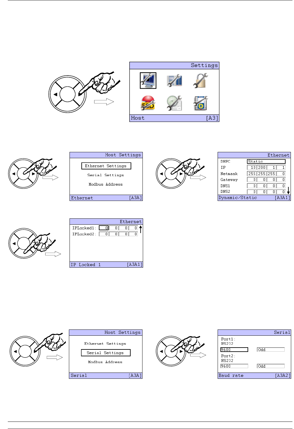
6. Setting Up the Master Station by the Keypad
Issue 05/12 Publication PUB059-002-00 45 of 134
BACK
NEXT
ENTER
BACK
NEXT
ENTER
BACK
NEXT
ENTER
BACK
NEXT
ENTER
BACK
NEXT
ENTER
BACK
NEXT
ENTER
6.5 Setting the Master Host Communications Parameters
Select the Host icon using the arrow keys ( or ) and press ENTER. The Host Settings menu
choices screen appears.
Select ‘Ethernet Settings’ using the arrow keys ( or ) and press Enter once more. The Ethernet
settings screen appears, note that there are two pages to the menu as indicated by the small arrow
() on the right side of the screen.
Use the NEXT button to move to the second page, the BACK button returns to the first page.
It is usually only necessary to change the IP address and Netmask to match the requirements of the
network connected to the master station. When making any change it will be necessary to enter the
PIN number for the master station as shown in the previous section.
To return to the previous Host Settings screen, press BACK and then select the Serial Settings using
the arrow keys ( or ) and press ENTER. The communications port speed (default 9600), and parity
are changed here.
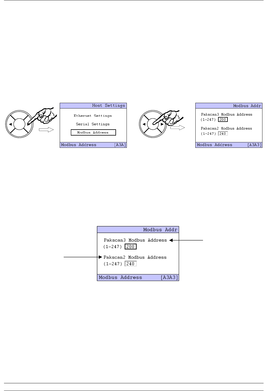
P3 - Pakscan Master Station Technical Manual
46 of 134 Publication PUB059-002-00 Issue 05/12
BACK
NEXT
ENTER
BACK
NEXT
ENTER
The port type is determined by the DIP switch settings on the main chassis behind the PS710 CPU
module and the setting is reflected in the message on the screen. If the port is set to RS-485 and
cross connected, the description changes to show these settings. This is particularly useful when
determining the settings already in place. Select the option to be changed by using the arrow keys (
or ), then ENTER (the PIN screen may appear before a change can be made). Once the PIN is
entered, the value of the parameter can be altered by the arrow keys ( or ). The speed can be
varied from 2400 to 115,200 and the parity may be Odd, Even, Zero or None. Once the value is as
required, press ENTER to set the value.
When the parameters are all as required, press BACK to return to the Host Settings screen, then
select the Modbus Address using the arrow keys ( or ) and press ENTER.
The Pakscan 3 Modbus address is for accessing the Wireless database.
The Pakscan 2 Modbus address is for accessing the Wired (current loop) database.
The Pakscan 2 and Pakscan 3 Modbus addresses MUST NOT be the same value.
The Modbus address for the communication to the actuators on the Pakscan 2 current loop (via the
module in option 2 slot) is altered in the lower window. It is recommended that this is altered to a value
other than the generic Modbus default address of 247 and the master Station defaults to ensure that
any new stations introduced do not conflict with this address.
The address is changed by first selecting it with the arrow keys, then pressing ENTER (if the PIN
requires entry the prompt page then appears). Use the arrow keys to change the number to the new
value, and then press ENTER once more. The new address becomes active once the screen has
been changed to a new one.
The Pakscan 3 wireless Modbus address is modified in the same way.
Change this
address for
communication with
the actuators
connected to the
current loop
module
Do not change
unless a Pakscan 3
option module is
fitted

6. Setting Up the Master Station by the Keypad
Issue 05/12 Publication PUB059-002-00 47 of 134
BACK
NEXT
ENTER
Once the settings are as required, use the BACK key to return to the top Settings menu.
6.6 The Other Settings
There are menus for setting all the parameters of the system. These are more fully explained in the
system manual and, in general, the default settings will allow most systems to operate with reasonable
success.
6.6.1 Security
Security is used for setting the PIN number to be used, plus the actions permitted from the keypad and
the serial ports via the Interlocks. The Security setting default requires a PIN for adjusting the settings
for system performance, but not for issuing actuator commands.
Interlocking controls the serial communications that are permitted to operate the actuators. The default
grants permission to all the serial ports and the Ethernet ports, but prevents the web page facility from
moving the valves.
The default PIN = 0000.
6.6.2 ESD
The default condition is to disable all the possible Emergency Shut Down routes. ESD can be enabled
from the serial ports, Ethernet ports, Web page, hard-wired input or keypad on an individual actuator
selection basis. If this ESD function is not required, ensure that a shorting link is fitted across pins 4
and 5 of the PS710 CPU module connector.
6.6.3 Date and Time
The date and time, plus the use of an NTP server are set from this menu. The time stamp is used for
the logging facility.

P3 - Pakscan Master Station Technical Manual
48 of 134 Publication PUB059-002-00 Issue 05/12
6.6.4 Master Station Parameters
The master station parameters include the Tag for the master station and the setting for data
transferred between the two CPU modules on a hot standby system along with several other
parameters. Most of the default settings are suitable on most systems, though there is one particular
set of parameters that must be correctly set in the case of hot standby systems.
The Serial Ports should appear as Passive if the Cross Connect DIP switch is set to ‘cross connect’. If
the port is set to RS-485 highway and is being used on a multi-drop highway it must be set to passive.
If it is not shown correctly it probably means the DIP switch is incorrectly set.
Remember, the default setting is Standby Active.

7. Internal Web pages
Issue 05/12 Publication PUB059-002-00 49 of 134
7. INTERNAL WEB PAGES
The master station includes a set of web pages that may be remotely accessed via Ethernet. They can
be used for setting up the system, examining the system for any faults or alarms and also for
controlling the actuators on the network (provided the Interlock permission is set to allow this feature).
If the master station is connected to an Ethernet Network it will act as a web server and any computer
within that network can connect to the master station. The master station can also be configured and
the field network set up by using these web pages. The host system or computer connected via the
Ethernet Network or directly will need a web browser such as Internet Explorer to access the master
station web pages.
7.1 Making an Internet / Intranet Connection
Connect the master station to an Ethernet host as described in section 5, or connect via a suitable
router to the internet / intranet. A computer can be connected directly to the master station using the
configuration port.
Start the browser and enter the IP address of the master station. The default address is 10.200.1.1, so
the address is http://10.200.1.1. The browser will then access the master station and bring up the
opening page of the master station. In order to log in as a verified user, enter a user name of admin
and a password of admin. (The default password should be altered as soon as convenient to prevent
unauthorised access to the system.)
Default IP address 10 . 200 . 1 . 1
Default User admin
Default Password admin
Once entry to the web pages has been made, if no changes to the display or information is made for a
few minutes, the system will automatically log out and the user/password must be re-entered.

P3 - Pakscan Master Station Technical Manual
50 of 134 Publication PUB059-002-00 Issue 05/12
7.2 Connecting a Computer Directly to the Master Station
The simplest direct connection to the master station is by using the Ethernet port on the front of the
CPU module. A standard Ethernet patch cable or crossover cable can be used to link the two directly.
A permanent connection can also be made directly to one of the underside connectors (port 3 or 4). In
order to establish a connection it is probably necessary to adjust the settings of the computer’s
Internet connection.
Fig 32: Connecting a Laptop to the Pakscan P3 Main Module
7.3 Adjusting the Network Settings of the Computer
Ensure that nothing is connected to the Ethernet port of the computer.
Open the Control Panel and select Network Connections (XP) or Network and Sharing Centre
(Windows 7).
Select Change Adaptor settings (Windows 7 only).
In the ‘Network Connections’ window, double-click on the appropriate ‘LAN or High Speed
Internet’ icon and the ‘Local Area Connection Status’ window will open.
Click on the ‘Properties’ button, and a second window will open. Select ‘Internet Protocol
TCP/IP’ (‘Internet Protocol Version 4 (TCP/IPv4)’ for Windows 7) and click on the ‘Properties’
button in this window.
The ‘Internet Protocol TCP/IP Properties’ window will open. Next, change the setting to force
the computer to adopt a fixed IP address and enter an address of 10.200.1.3 and a subnet
mask of 255.255.255.0. Click on the ‘OK’ button and the window will close.
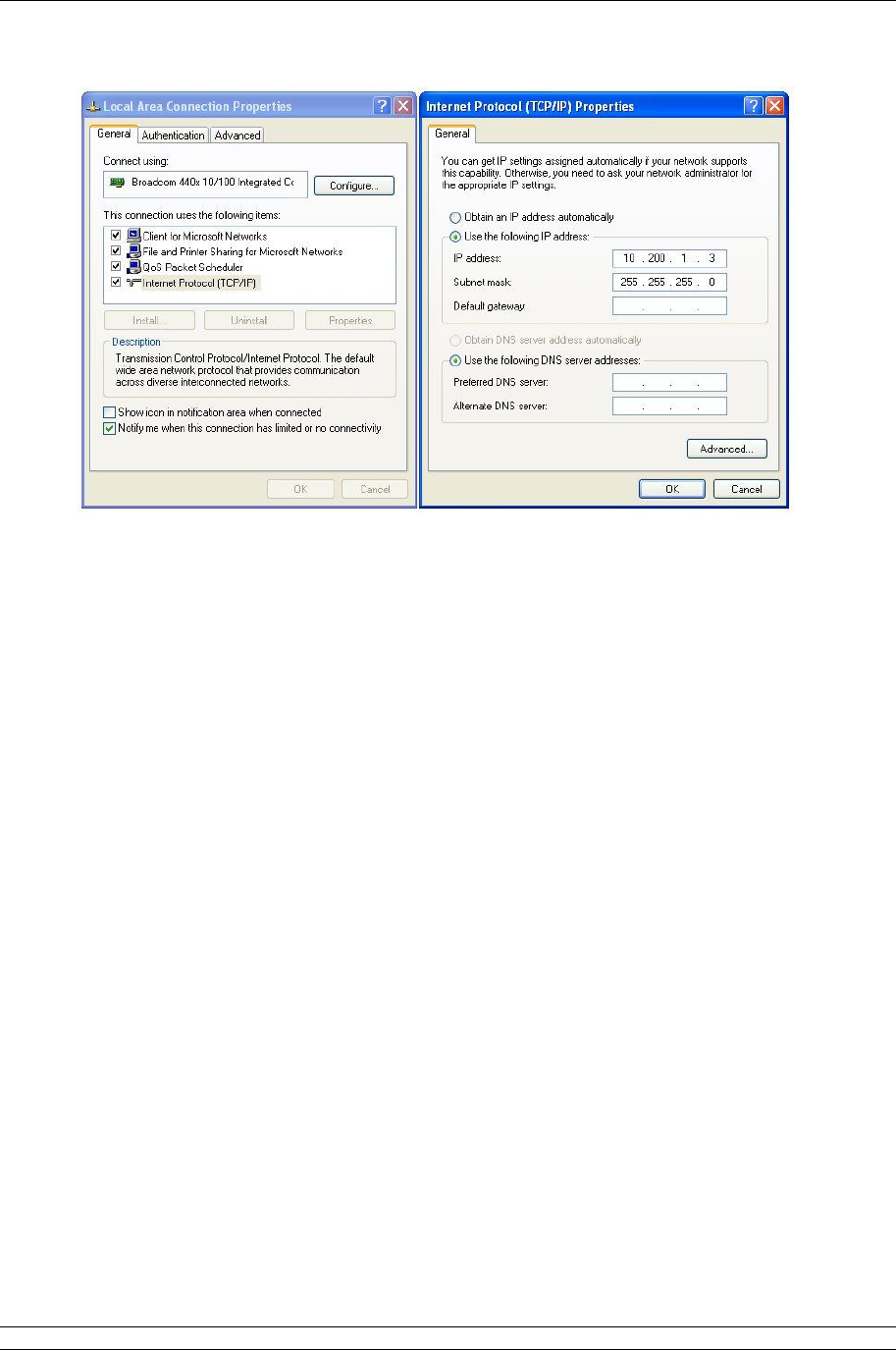
7. Internal Web pages
Issue 05/12 Publication PUB059-002-00 51 of 134
Fig 33: Changing the Network Connections TCP/IP Properties – Windows XP
Click OK on the ‘Local Area Connection Properties’ window and then close the status window.
Finally, close the ‘Network Connections’ window and the Control Panel.
It may be necessary to reboot the computer to be sure that the new settings take effect
correctly.
Connect the cable between the computer and the Pakscan master station.
Start the browser and enter the IP address of the master station. The default address is
10.200.1.1, so set the address to http://10.200.1.1. The browser will then access the master
station and bring up the opening page of the master station. In order to log in as a verified
user, enter the username of admin and the password admin.
Note: If the IP address of the master station has been changed from the defaults, then the settings
above will not work and will have to be modified to suit the actual settings.

P3 - Pakscan Master Station Technical Manual
52 of 134 Publication PUB059-002-00 Issue 05/12
7.4 Web Page Structure
The web pages have three access levels, each requiring a password with the correct level set. A user
enters the web server with a particular degree of access to the functions of the server and the master
station.
7.4.1 User Levels
Access Level Function
Lowest level Read
Allows access to read master station status and settings,
plus the option module status and settings, plus the
actuator and field unit status on the option module network.
No commands or alterations to the system are permitted.
Write As for read access with the addition of the ability to issue
network commands, swap masters and command
actuators on the option module network to change position.
Highest Level Administrator
As for the two lower levels plus the ability to configure the
master station, option modules and all system settings. Set
and remove user names and passwords; set alarm
reporting parameters, change system addresses and test
system communications.
The Administrator level sets all other user names and passwords. As soon as the system is set up the
default password should be changed. Make sure all changes made to log in details are recorded.
7.4.2 Overview of Web Page Layout
The web pages are organised using a menu structure with the primary menu on the top of each page.
Within a page there are other controls for parameter alteration or to reveal extended information on
the topic of the particular page.
Navigation between the pages is by selecting another topic on the main menu.
If there is no activity with the mouse to change the display or update the information or selection for a
few minutes, the system automatically logs out the user. The username and password must be re-
entered to continue using the pages.

7. Internal Web pages
Issue 05/12 Publication PUB059-002-00 53 of 134
Log In
Master Station
View
Configuration
System
Diagnostics Master Station Log
Host Analyser
Option Diagnostics Network
Diagnostics
Option Event Log
FCU Menu FCU
Admin* Users
Master Station and
Option Configuration
Host Ports
Alarms
Time
General
Network
* requires Admin level log in
Fig 34: Web Page Menu Layout
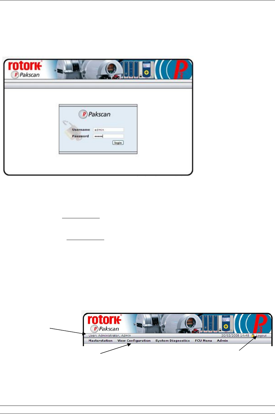
P3 - Pakscan Master Station Technical Manual
54 of 134 Publication PUB059-002-00 Issue 05/12
7.5 The Web Pages in Detail
7.5.1 Log In Screen
Fig 35: Web page Log In Screen
The first screen is the Log In screen on which the user must enter a Username and Password.
Username - a case sensitive identification for an individual or group used to give access to
the system. User names are listed for administrators to see on the ‘Add User’ page.
Password - the case sensitive confirmation required before a username is accepted by the
system. Passwords are not listed on any page in the system and cannot be retrieved, even at
the administrator level.
Select the box with the mouse and enter the appropriate name or password, then click on the login
button. The system will move to the next page if the login is accepted. If it fails, the data is cleared
from the boxes and must be re-entered correctly in both boxes before access is granted.
The default user name is admin and default password is admin. The password should be altered as
soon as convenient to prevent unauthorised access to the system.
Fig 36: Web page Header Navigation
User name and
access level.
Menu of available screens to visit
(changes to blue when selected) for
Read and Write access levels
Log out when finished by
clicking here (changes to
red when selected).
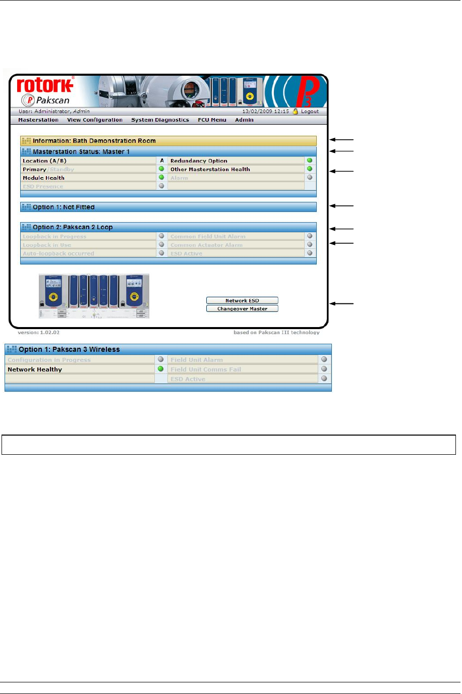
7. Internal Web pages
Issue 05/12 Publication PUB059-002-00 55 of 134
7.5.2 Master Station
Fig 37: Master Station Overview web page and Option 1 data, if a Wireless module is fitted
This screen reports the current status of the master station and the option modules fitted. The picture
shows the master station, single or hot standby version. The green, orange and red lights show the
condition of the associated parameter. Greyed out text and lights are not applicable or else in a safe
(normal) condition.
Master station CPU Module
Site name : The name of the site where the system is located, as entered during
configuration.
Tag name : The master station tag, as entered during configuration.
Status
Location A/B : Indicates the CPU module currently in communication over the Ethernet.
Site Name
Option Module 1
Tag Name
Status
Option Module 2
Status
Controls
This screen is accessible to Read, Write and Administrator user levels.

P3 - Pakscan Master Station Technical Manual
56 of 134 Publication PUB059-002-00 Issue 05/12
Primary/Standby : Shows the condition of the CPU with regard to controlling the option
modules. The Primary CPU is in control. A Standby CPU is prepared to
become the Primary and take control if the partner unit fails.
Module Health : Indicates the absence (green light) or presence (red light) of a fault on the
CPU.
ESD Presence : Shows a yellow light if an Emergency Shut Down signal is active.
Redundancy : Shows a green light if there is a partner module fitted.
Option
Other Master : Indicates the absence (green light) or presence (red light) of a fault on the
Station health partner CPU.
Alarm : Indicates the presence of an alarm (red light) somewhere on the system.
Option 1 and Option 2 - Show the type of Option module fitted, either:
Pakscan 2 Loop Option Module
Loopback in : A blue light shows whilst the master station is reconfiguring the loop.
Progress
Loopback in Use : A yellow light shows when the master station has detected a loopback fault
on the system.
Auto Loopback : If a fault occurs on the network and an automatic reconfiguration of the
occurred loop occurs, then a yellow light is shown here.
Common Field : A red light shows if any field unit on the network has an alarm bit present.
Unit Alarm
Common : A red light shows if any actuator on the network is unavailable due to its
Actuator Alarm monitor relay having tripped.
ESD Active : If there is an Emergency Shut Down signal present on the system a red
light shows.
Pakscan 3 Wireless Option Module
Configuration in
Progress : A blue light shows whilst the master station is reconfiguring the network.
Network Healthy
: A
Green
light shows when the master station has detected
NO
fault
s
in
the network and it is healthy.
Field Unit Alarm : A Red light shows when the master station has detected an alarm on any
of the field units.
Field unit Comms
fail : A Red light shows when the master station has detected a
communications failure to a field unit.
ESD Active : If there is any Emergency Shut Down signal present for that network on
the system a red light shows.
Controls - Not Available for Read level users
Network ESD : Click here to issue an ESD to all actuators connected to both option
modules. The resulting action will depend on the individual actuator
settings. A confirmation screen appears to verify or cancel the instruction
before the action occurs.
Changeover : Only applicable to hot standby systems. Click this button to make the
Master master station CPU in control; change from A to B or B to A.

7. Internal Web pages
Issue 05/12 Publication PUB059-002-00 57 of 134
7.5.3 View Configuration
Fig 38: System Configuration Overview web page
The screen shows the settings for the control of the option module networks and the CPU control
capability, software fitted and various options selected. All of these settings can be modified
elsewhere, but only by users with Administrator level access. There are no controls on this page.
The settings are explained in the Master Station Configuration page section.
This screen is accessible to Read, Write and Administrator user levels.
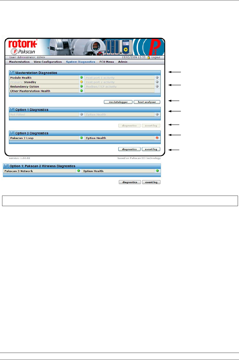
P3 - Pakscan Master Station Technical Manual
58 of 134 Publication PUB059-002-00 Issue 05/12
7.5.4 System Diagnostics
Fig 39: System Diagnostics web page wired only and option 1 data, if wireless fitted
The System Diagnostics screen shows an overview of the status of the fitted modules and also
provides access to further information.
Master Station Diagnostics
Module Health : A green light shows if the module is operating correctly, changes to red if
there is a fault.
Primary/Standby : Indicates which module is being accessed. A green light indicates Primary,
a yellow light indicates Standby and a red light indicates a fault.
Redundancy : Shows a green light if there is a partner module fitted.
Option
Other Master : Indicates the absence (green light) or presence (red light) of a fault on the
Station Health partner CPU.
Host port 1 : Indicates when there is serial communication taking place on
activity communications port 1.
Host port 2 : Indicates when there is serial communication taking place on
activity communications port 2.
Modbus/TCP : Indicates when Ethernet control using Modbus/TCP is present on either
activity Ethernet port.
Master Station CPU
Option Module 1
Status
Option Module 2
Controls
Controls
This screen is accessible to Read, Write and Administrator user levels.
Controls

7. Internal Web pages
Issue 05/12 Publication PUB059-002-00 59 of 134
Controls - Available to all user levels
ms datalogger : Reveals a pop-up showing a log of the activity on the master station and
the source of requests or commands received. See section 7.5.5 for
details.
host analyser : Reveals a pop-up with the data logger data and the additional controls
required for using the inbuilt data analyser for commands and data sent to
the host system. See section 7.5.6.
Option 1 Diagnostics
Pakscan
wireless network
: Shows module type and status, or ‘Not Fitted’ when there is nothing in the
slot.
Option Health : Shows a green light when healthy and a red light if there is a fault on the
module.
Option 2 Diagnostics
Pakscan 2 Loop : Shows module type and status, or ‘Not Fitted’ when there is nothing in the
slot.
Option Health : Shows a green light when healthy and a red light if there is a fault on the
module.
Controls - Available (when module fitted) to all user levels
diagnostics : Reveals the diagnostic page for the option module fitted. See section 7.5.7
Pakscan 2 Loop and section 7.5.8 Pakscan Wireless.
event log : Shows the option module event recorder. See section 7.5.9 Pakscan 2
Loop and section 7.5.10 Pakscan Wireless.
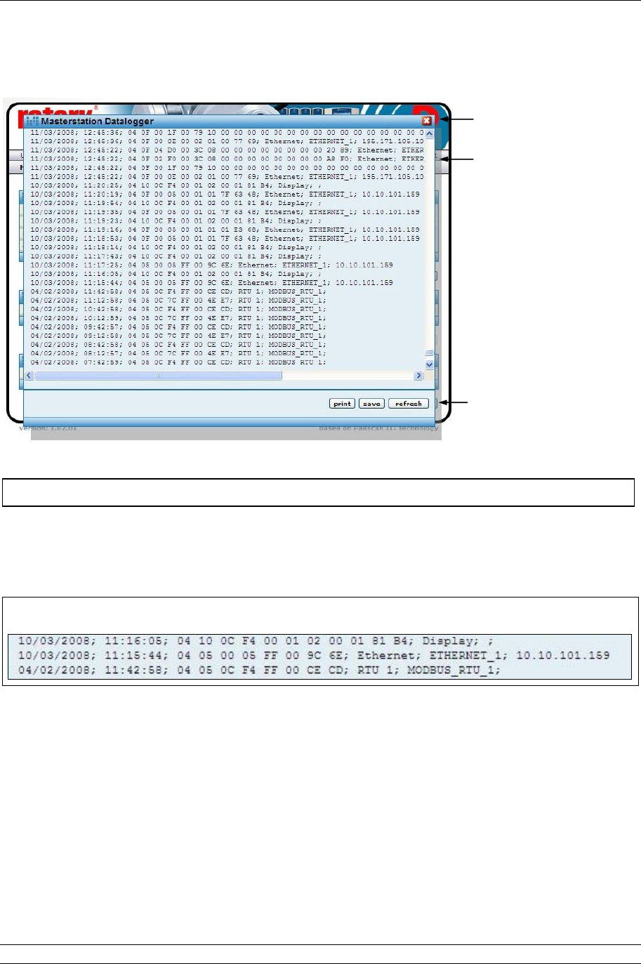
P3 - Pakscan Master Station Technical Manual
60 of 134 Publication PUB059-002-00 Issue 05/12
7.5.5 Master Station Data Logger [ms datalogger]
Fig 40: Master Station Data Logger pop-up
The data logger displays Modbus instructions received by the master station to carry out commands
such Alarm Accept or commands to move a valve. Each event is prefixed by a date and time and they
are listed in time order. They are followed by the source from which the command originated. Once full
the log rolls over and rewrites over the oldest events, the log is 1Mbyte in size.
Fig 41: Close up of Master Station Data Logger Information
Date and Time
Formatted Day/Month/Year or Month / Day / Year.
Modbus Message
Standard Modbus RTU format for all ‘write’ messages.
Message Source and Address
Display : Keypad on the master station CPU.
Ethernet : Ethernet input and IP address of the source.
RTU : Serial port 1 (RTU 1) or serial port 2 (RTU 2).
Webpages : Web page Log In name and IP address.
Master Station
Events
Controls
This screen is accessible to Read, Write and Administrator user levels.
Close pop-up
Date and Time Modbus Message Message Source / Address
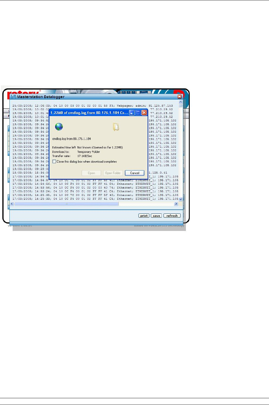
7. Internal Web pages
Issue 05/12 Publication PUB059-002-00 61 of 134
Controls - Available to all user levels
Print : Prints the logger data to a printer attached to the computer.
Save : Saves the logger data to a file on the computer.
The saved file is of the type cmdlog.log and can be opened in the Notepad
on the computer. It can also be imported into a spreadsheet, such as
Excel, for analysis as required.
Refresh : Updates the screen with any new data.
Fig 42: Saving the master station log file
P3 - Pakscan Master Station Technical Manual
62 of 134 Publication PUB059-002-00 Issue 05/12
7.5.6 Master Station Host Analyser [host analyser]
Fig 43: Host Analyser pop-up
The Host Analyser is a real time system analyser that can be used with either a Modbus RTU serial
data control source, acting through one of the serial data ports (Port 1 or 2), or a Modbus TCP
Ethernet control source, acting through the Ethernet ports.
The analyser will record up to 100 messages (requests and responses) on the data line between the
two points. It is especially useful for debugging a host control system to ensure that messages are
correctly formatted and that the required control or data points are being accessed. In particular, the
use of correct offsets in the Modbus protocol can be checked.
Controls - Available to Administrator user level
RTU1 : Selects Serial Port 1 host input.
RTU2 : Selects Serial Port 2 host input.
ETH : Selects the Ethernet port host input (all Ethernet ports are monitored).
Print : Prints the analyser data to a printer attached to the computer.
Save : Saves the analyser data to a file on the computer.
Refresh : Updates the screen with any new data.
Analyser Events
Controls
This screen may be used by Administrator user level only.
Close pop-up
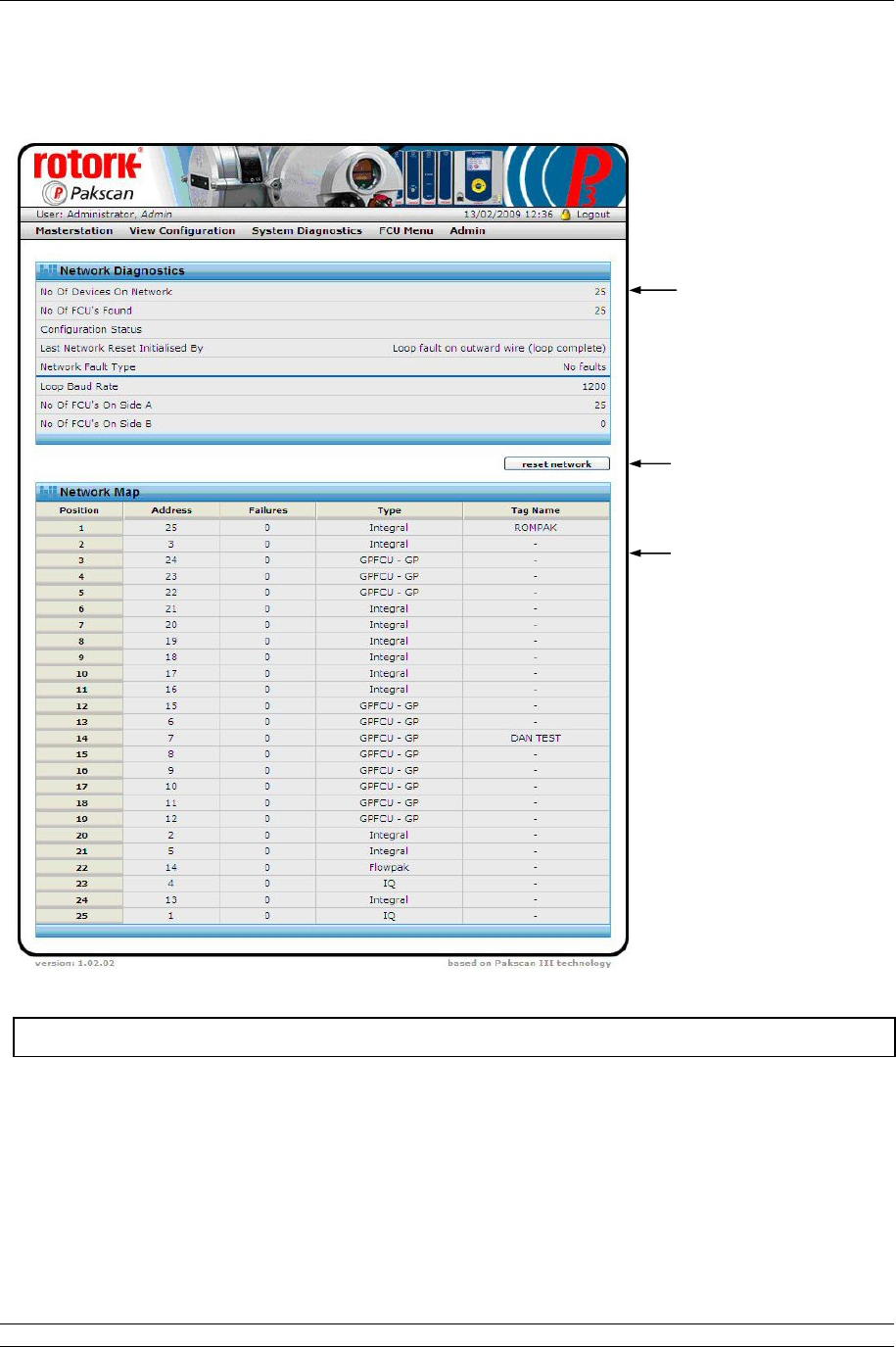
7. Internal Web pages
Issue 05/12 Publication PUB059-002-00 63 of 134
7.5.7 Pakscan 2 Loop Diagnostics [diagnostics]
Fig 44: Pakscan 2 Loop Diagnostics web page
The Pakscan 2 Loop Diagnostics screen gives diagnostic information on the 2-wire loop option module
and the network connected to it. The top part of the screen shows the information about the option
module itself, whilst the lower part shows the loop map. This is the order in which the field units on the
2-wire loop are connected. It also shows the device type and tag name for each address and position.
Network Information
Controls
Network FCU Map
This screen is accessible to Read, Write and Administrator user levels.

P3 - Pakscan Master Station Technical Manual
64 of 134 Publication PUB059-002-00 Issue 05/12
Network Diagnostics
No. Of Devices : This is the number of field units that are expected to be located on the
On Network network. It is the highest address that the network will scan up to when
locating field units. All field units need to be consecutively addressed, and
there should be no gaps in the addresses.
No. Of FCUs : This is the total number of field units located on the network. If all the field
Found units are powered on and connected, then the number will equal the No. Of
Devices On The Network above.
Configuration : This field shows any fault that exists on the network cabling and the stages
Status passed through as network configuration takes place.
During configuration the following sequence can be displayed -
1. Wait for Loopbacks 1 (first wait for loopbacks to come on)
2. Find FCUs on Port A (finding FCUs on port A)
3. Test Loop (testing for complete loop)
4. Find FCUs on Port B (finding FCUs on port B)
5. Wait for Loopbacks 2 (second wait for loopbacks to come on)
6. Loopbacks off on A (removing loopbacks from port A)
7. Loopbacks off on B (removing loopbacks from port B)
(The normal sequence for a fault-free loop would be 1, 2 and 3. A
sequence for a break in the loop, anywhere except at port A or port B,
would be 1 to 7. Some of the phases may be very quick, particularly at
higher baud rates, and so may not be seen on the browser display.
Whilst the configuration is taking place, the master station web page shows
‘Loopback in Progress’ and a blue light on the Option module.
If the configuration process detects a fault on the loop and switches on the
loopback circuits of two field units, the master station web page shows
‘Loopback in Use’ and illuminates the yellow light.
Last Network : The loop can be reconfigured for a number of reasons and this field will
Reset Initiated show the cause of the last reset/reconfigure that occurred.
By The possible reasons are:
Power on Reset - loop configured because the master station
powered up.
Fault Found - fault detected on the loop whilst it was running
without loopbacks present.
Fault Found A - fault detected on the A side of broken loop whilst
running with loopbacks on.
Fault Found B - fault detected on the B side of broken loop whilst
running with loopbacks on.
Reset Command - loop Reconfigure command entered from keypad
or serial port.
Return wire fault - fault detected in the return current path whilst the
loop was running at double speed.
Doubling failed - fault detected after loop assumed double speed.

7. Internal Web pages
Issue 05/12 Publication PUB059-002-00 65 of 134
Network Fault : This field shows the type of fault detected that caused the loopback to
Type occur, or an addressing fault on the field units. The types are:
Zero Address - a field unit has been found with an address
of zero.
Address too High xx - a field unit has been found with an address
higher than that set up within the master
station; xx is the address.
Same Address xx - two field units found with the same
address; xx is the address.
Loop Open Circuit - an open-circuit fault found on the loop.
Loop Short Circuit - a short-circuit fault found on the loop.
If two field units are found with the same address, or there is an address
outside the range of addresses expected (as set by No. of Devices on
Network), the network will continue to operate and miss out the faulty field
units.
Loop Baud Rate : Shows the current speed selected. The speed can be 110, 300, 600, 1200,
or 2400 baud.
No. Of FCUs : This is the total number of field units connected to the option module Port A
On Side A and communicating via Port A.
No. Of FCUs : This is the total number of field units connected to the option module Port B
On Side B and communicating via Port B. Port B is only used if there is a loopback
present on the network.
Controls - Available to all user levels
Reset network : Causes the option module to reconfigure the 2-wire network. This should
be used after a loop fault has been corrected.
Network Map
The map shows the order in which the field units have been identified and found by the option
module during the last loop reconfiguration process (reset). Each time the loop is reconfigured
the map is regenerated and repopulated. Any field unit that is not powered-up at the time of
reconfiguration will be absent from the map.
Position : The position in the loop. Number 1 is nearest to Port A.
Address : The address of the field unit.
Failures : Shows a count of communication errors with the field unit. The count has a
range of 0 to 255, after which it rolls around to zero and it increments for
every communication error. The system will only announce a ‘Comms
failure’ when 3 successive tries have failed to locate the field unit. This
counter therefore reflects the communications condition and can be used
as an indicator of the health of the field unit to assess the probability of
failure in the future.
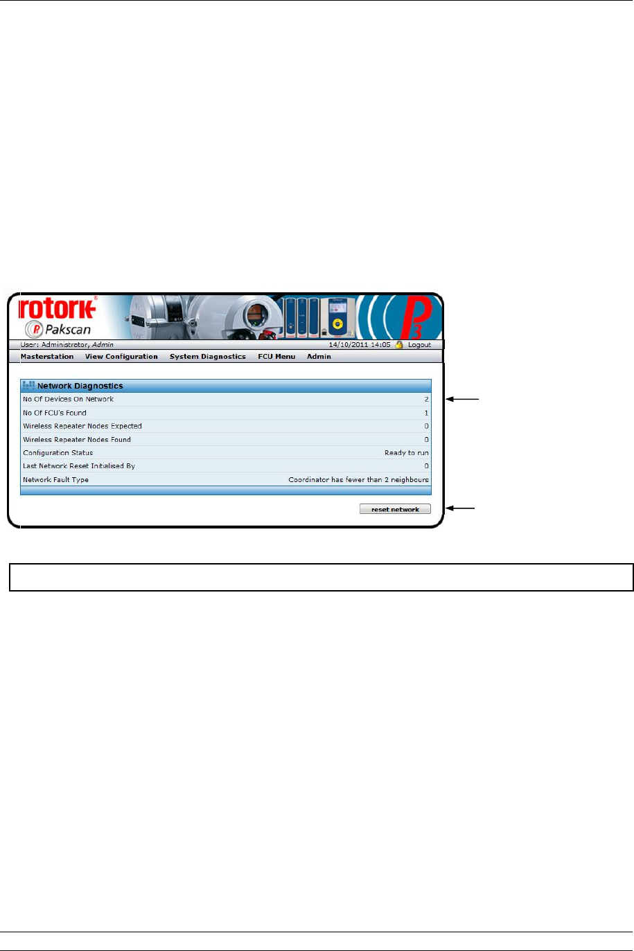
P3 - Pakscan Master Station Technical Manual
66 of 134 Publication PUB059-002-00 Issue 05/12
Type : The type of field unit depends on the actuator and function required.
Current types are -
IQ - IQ or IQT actuator
Integral - Non IQ actuator
Flowpak - Flowpak actuator
GPFCU - GP - General Purpose Field Unit
GPFCU - Act - General Purpose in Actuator mode
IQA - IQ Analogue card
ROMpak - ROMpak actuator
Tag Name : The associated identification Tag assigned to this field unit.
7.5.8 Pakscan Wireless Diagnostics [diagnostics]
Fig 45: Pakscan Wireless Diagnostics web page
The Pakscan Wireless Diagnostics screen gives diagnostic information on the wireless option module
and the network connected to it.
No of Devices
On Network : This is the number of wireless field units that are expected to be located
on the network. This is set up in the master station configuration web
page.
No of FCUs
found : This is the total number of field units found on the network. If all the field
units are powered on and able to communicate, the number will equal
the number expected on the network.
Wireless
repeater nodes
expected
: This is the number of wireless repeater modules that are expected to be
located on the network. This is set up in the master station configuration
web page.
Wireless
repeater nodes
found
: This is the total number of wireless repeater nodes found on the
network. If all the repeater nodes are powered on and able to
communicate, the number will equal the number expected on the
Network Information
Controls
This screen is accessible to Read, Write and Administrator user levels.

7. Internal Web pages
Issue 05/12 Publication PUB059-002-00 67 of 134
network.
Configuration
Status
: During configuration of the wireless network the network goes through
various stages as indicated below. Some of the stages can be quite
quick and therefore may not be seen:
Uninitialised.
Initialised / starting up.
Detecting field units.
Building map of field units.
Detecting field units complete.
Obtaining initial field unit data.
Field unit data collection complete.
Network Ready to run.
Master station updating RF parameters.
After a reset network command is sent from the web page, the normal
sequence seen would be: Initialised / starting up, Detecting Complete,
Obtaining initial Data, Data collection complete, Ready to run.
‘Ready to run’ is the normal state of a good network.
Last Network
Reset Initialised
By
: This field indicates the cause of the last reset, this can either be due to a
power cycle (value will be 00), as a result of receiving a reset network
command, due to a parameter change causing the Coordinator to reset
or due to a Radio communications parameter change.
Network Fault
Type : This field indicates any faults on the network. Faults reported can be:
Wireless coordinator fault.
Insufficient wireless neighbours for the coordinator or the field
units, the intention is always to have at least 2 neighbours.
RF parameter change failed.
Duplicate field unit address detected.
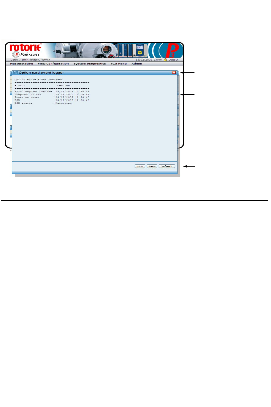
P3 - Pakscan Master Station Technical Manual
68 of 134 Publication PUB059-002-00 Issue 05/12
7.5.9 Pakscan 2 Loop Option Module Event Logger [Event Log]
Fig 46: Wired Option Module Event Logger pop-up
The event logger shows the last occurrence of the listed events and, in the case of an ESD, where the
signal originated.
Controls - Available to all user levels
Print : Prints the logger data to a printer attached to the computer.
Save : Saves the logger data to a file on the computer.
Refresh : Updates the screen with any new data.
Event Log
Controls
This screen is accessible to Read, Write and Administrator user levels.
Close pop-up

7. Internal Web pages
Issue 05/12 Publication PUB059-002-00 69 of 134
7.5.10 Pakscan Wireless Option Module Event Logger [Event Log]
Fig 47: Wireless Option Module Event Logger pop-up
The event logger shows the last occurrence of the listed events. In the case of an ESD, where the
ESD signal originated is reported. In the case of the last field unit comms fail, it also indicates which
field unit lost communications.
Controls - Available to all user levels
Print : Prints the logger data to a printer attached to the computer.
Save : Saves the logger data to a file on the computer.
Refresh : Updates the screen with any new data.
Event Log
Controls
This screen is accessible to Read, Write and Administrator user levels.
Close pop-up
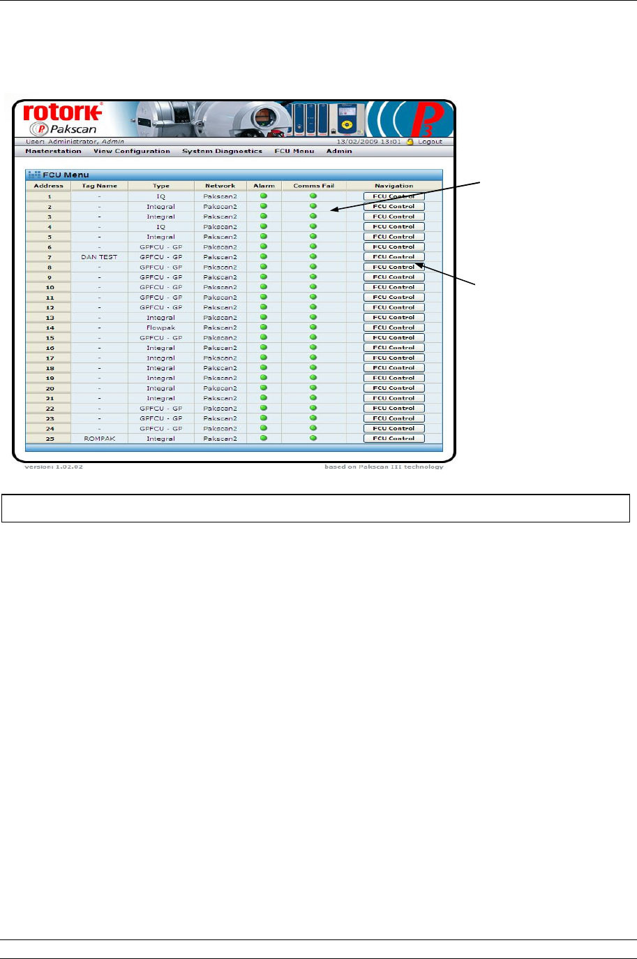
P3 - Pakscan Master Station Technical Manual
70 of 134 Publication PUB059-002-00 Issue 05/12
7.5.11 FCU Menu
Fig 48: FCU Menu web page
The FCU Menu lists all the field units in address order (which may not be the same as the order in
which they are connected together on the wired loop).
For each address, the Tag name and Type of field unit is listed. Field unit types are described in
section 7.5.7. The Network column shows which option module network each actuator is connected to;
this will be Pakscan 2 for the 2-wire loop option module and Wireless for the wireless option.
The next two columns show critical alarm conditions that will prevent remote control of the actuator.
An Alarm present will generally prevent operation, whilst Comms Fail indicates that the actuator is no
longer in communication with the field network.
The final column has Navigation controls to the individual FCU screens.
Controls - Available to all user levels
FCU Control : Click here to show the selected FCU individual control panel web page.
The different types of devices each have different screens and only the
relevant data and controls for each type are included on the screen,
together with a picture identifying the type of device.
When not in communication the screen may still be visited, but the actuator
picture will have a large red cross over it to show that a problem exists.
This screen is accessible to Read, Write and Administrator user levels.
Network Information
Controls