Rts Kgatx0101400 Users Manual 0G1622 Rev0
KGATX0101400 to the manual fffd27ed-5620-4fcf-aa62-9a98225364d1
2015-02-06
: Rts Rts-Kgatx0101400-Users-Manual-525552 rts-kgatx0101400-users-manual-525552 rts pdf
Open the PDF directly: View PDF ![]() .
.
Page Count: 16

TECHNICAL
MANUAL
This manual should remain with the unit.
RTS Automatic Transfer Switch
400A, 120/240V, Single-phase
Model No.: KGATX0101400
A new standard of reliability

The manufacturer cannot anticipate every possible
circumstance that might involve a hazard. The warn-
ings in this manual, and on tags and decals affixed
to the unit are, therefore, not all-inclusive. If using
a procedure, work method or operating technique
the manufacturer does not specifically recommend,
ensure that it is safe for others. Also make sure the
procedure, work method or operating technique uti-
lized does not render the transfer switch unsafe.
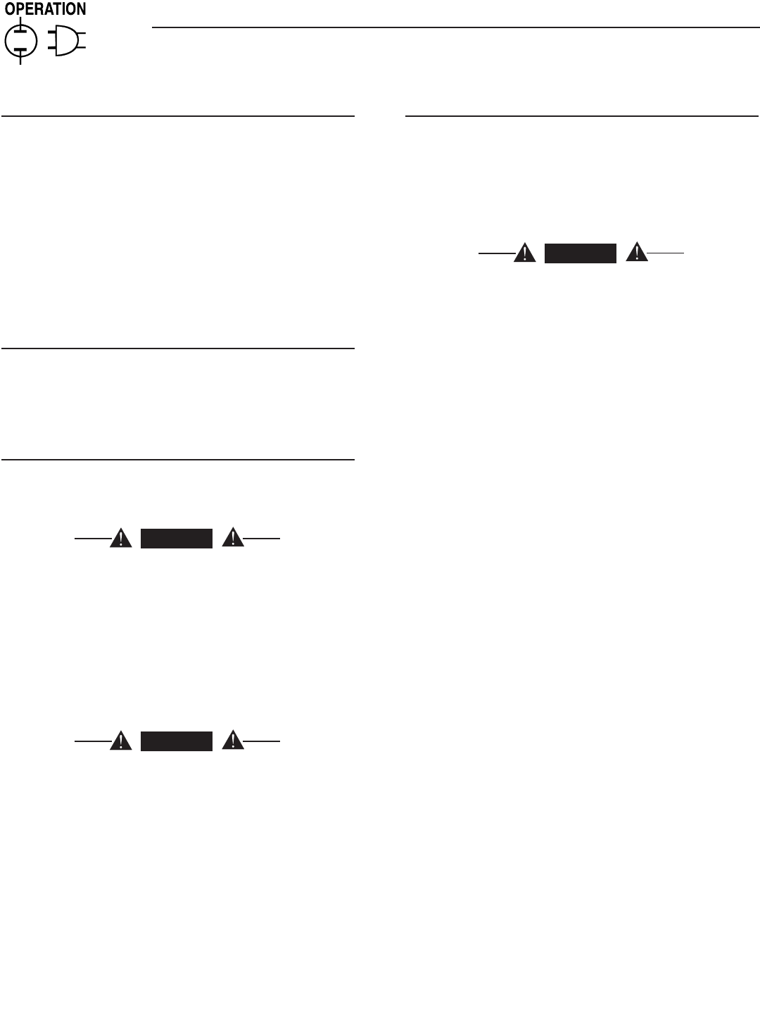
Throughout this publication, and on tags and decals
affixed to the generator, DANGER, WARNING,
CAUTION and NOTE blocks are used to alert person-
nel to special instruction about a particular operation
that may be hazardous if performed incorrectly or
carelessly. Observe them carefully. The definitions
are as follows:
DANGER
After this heading, read instructions that, if not
strictly complied with, will result in personal injury
or property damage.
After this heading, read instructions that, if not
strictly complied with, may result in personal inju-
ry or property damage.
After this heading, read instructions that, if not
strictly complied with, could result in damage to
equipment and/or property.
NOTE:
After this heading, read explanatory statements
that require special emphasis.
These safety warnings cannot eliminate the hazards
that they indicate. Common sense and strict compli-
ance with the special instructions while performing
the service are essential to preventing accidents.
Four commonly used safety symbols accompany the
DANGER, WARNING and CAUTION blocks. The type
of information each indicates follows:
This symbol points out important safety infor-
mation that, if not followed, could endanger
personal safety and/or property of others.
This symbol points out potential explosion
hazard.
This symbol points out potential fire hazard.
This symbol points out potential electrical shock
hazard.
GENERAL HAZARDS
• Any AC generator that is used for backup power if
a NORMAL (UTILITY) power source failure occurs,
must be isolated from the NORMAL (UTILITY)
power source by means of an approved transfer
switch. Failure to properly isolate the NORMAL
and STANDBY power sources from each other may
result in injury or death to electric utility workers,
due to backfeed of electrical energy.
• Improper or unauthorized installation, operation,
service or repair of the equipment is extremely
dangerous and may result in death, serious per-
sonal injury, or damage to equipment and/or per-
sonal property.
• Extremely high and dangerous power voltages are
present inside an installed transfer switch. Any
contact with high voltage terminals, contacts or
wires will result in extremely hazardous, and pos-
sibly LETHAL, electric shock. DO NOT WORK ON
THE TRANSFER SWITCH UNTIL ALL POWER
VOLTAGE SUPPLIES TO THE SWITCH HAVE
BEEN POSITIVELY TURNED OFF.
• Competent, qualified personnel should install,
operate and service this equipment. Adhere strictly
to local, state and national electrical and building
codes. When using this equipment, comply with
regulations the National Electrical Code (NEC),
CSA Standard; C22.1 Canadian Electric Code and
Occupational Safety and Health Administration
(OSHA) have established.
• Never handle any kind of electrical device while
standing in water, while barefoot, or while hands or
feet are wet. DANGEROUS ELECTRICAL SHOCK
MAY RESULT.
Important Safety Instructions
Read the following information carefully before attempting to install, operate or service this
equipment. Also read the instructions and information on tags, decals, and labels that may
be affixed to the transfer switch. Replace any decal or label that is no longer legible.
DANGER! Connection of a generator to an electrical system normally supplied by an electric
utility shall be by means of suitable transfer equipment so as to isolate the electric system
from utility distribution system when the generator is operating (Article 701 Legally Required
Standby Systems or Article 702 Optional Standby Systems, as applicable). Failure to isolate
electric system by these means may result in damage to generator and may result in injury
or death to utility workers due to backfeed of electrical energy.

Table of Contents
1
Safety Rules .........................................Inside Front Cover
Section 1 — General Information ...................................2
1.1 Introduction............................................................. 2
1.2 Equipment Description ........................................... 2
1.3 Transfer Switch Data Label ..................................... 2
1.4 Transfer Switch Enclosure ...................................... 2
1.5 Safe Use of Transfer Switch .................................... 2
Section 2 — Installation ....................................................3
2.1 Introduction to Installation ...................................... 3
2.2 Unpacking ............................................................... 3
2.3 Mounting ................................................................. 3
2.4 Connecting Power Source and Load Lines ............... 3
2.4.1 2-Pole Mechanism ......................................... 3
2.5 Connecting Start Circuit Wires ................................ 4
2.6 Auxiliary Contacts.................................................... 4
Section 3 — Operation .......................................................4
3.1 Functional Tests & Adjustments .............................. 4
3.2 Manual Operation .................................................... 5
3.2.1 Close to Normal Source Side ........................ 5
3.2.2 Close to Emergency Source Side ................... 6
3.2.3 Return to Normal Source Side ...................... 6
3.3 Voltage Checks ......................................................... 6
3.3.1 Utility Voltage Checks .................................... 6
3.3.2 Generator Voltage Checks.............................. 6
3.4 Generator Tests Under Load ................................... 7
Section 4 – Installation Diagram ....................................8
Section 5 – Electrical Data ...............................................9
Section 6 – Exploded Views & Parts Lists ..................12
Section 7 – Warranty ...................................... Back Cover
• Because jewelry conducts electricity, wearing it
may cause dangerous electrical shock. Remove
all jewelry (such as rings, watches, bracelets, etc.)
before working on this equipment.
• If work must be done on this equipment while
standing on metal or concrete, place insulative
mats over a dry wood platform. Work on this
equipment only while standing on such insulative
mats.
• Never work on this equipment while physically or
mentally fatigued.
• Keep the transfer switch enclosure door closed
and bolted at all times. Only qualified personnel
should be permitted access to the switch interior.
• In case of an accident caused by electric shock,
immediately shut down the source of electrical
power. If this is not possible, attempt to free the
victim from the live conductor but AVOID DIRECT
CONTACT WITH THE VICTIM. Use a nonconduct-
ing implement, such as a rope or board, to free
the victim from the live conductor. If the victim
is unconscious, apply first aid and get immediate
medical help.
• When an automatic transfer switch is installed for
a standby generator set, the generator engine may
crank and start at any time without warning. To
avoid possible injury that might be caused by such
sudden start-ups, the system’s automatic start cir-
cuit must be disabled before working on or around
the generator or transfer switch. Turn the genera-
tor’s AUTO/OFF/MANUAL switch to OFF. Turn the
generator’s main circuit breaker OFF. Then place
a “DO NOT OPERATE” tag on the transfer switch
and on the generator. Remove the Negative (Neg) or
(–) battery cable.
2
Section 1 — General Information
RTS “W” Type Transfer Switch
1.1 INTRODUCTION
This manual has been prepared especially for the
purpose of familiarizing personnel with the design,
application, installation, operation and servicing of
the applicable equipment. Read the manual carefully
and comply with all instructions. This will help to
prevent accidents or damage to equipment that might
otherwise be caused by carelessness, incorrect appli-
cation, or improper procedures.
Every effort has been expended to make sure that the
contents of this manual are both accurate and cur-
rent. The manufacturer reserves the right to change,
alter or otherwise improve the product at any time
without prior notice.
1.2 EQUIPMENT DESCRIPTION
The automatic transfer switch is used for transferring
critical electrical loads from a UTILITY (NORMAL)
power source to an EMERGENCY (GNERATOR)
power source.
The transfer switch prevents electrical feedback
between the UTILITY and EMERGENCY sources. For
that reason, electrical codes require a transfer switch
in all standby electric system installations.
When the transfer switch is connected to the engine
generator control panel, the control panel constantly
monitors the UTILITY voltage and controls the opera-
tion of the transfer switch.
Should the UTILITY voltage drop below a preset value,
and remain at this low voltage for a preset amount of
time, the generator cranks and starts. After the gen-
erator starts, the transfer switch transfers the load
circuits to the generator, the generator then supplies
the loads. When UTILITY returns above a preset level
the load is transferred back to the UTILITY and the
generator shuts down.
1.3 TRANSFER SWITCH DATA LABEL
A DATA LABEL is permanently affixed to the transfer
switch enclosure. Use this transfer switch only with
the specific limits shown on the DATA LABEL and
on other decals and labels that may be affixed to the
switch. This will prevent damage to equipment and
property.
When requesting information or ordering parts for this
equipment, make sure to include all information from
the DATA LABEL.
Record the Model and Serial numbers in the space
provided below for future reference.
1.4 TRANSFER SWITCH ENCLOSURE
The standard switch enclosure is a National Electrical
Manufacturer’s Association (NEMA) and UL 3R type.
UL and NEMA 3R type enclosures primarily provide
a degree of protection against falling rain and sleet;
undamaged by the formation of ice on the enclosure.
1.5 SAFE USE OF TRANSFER SWITCH
Before installing, operating or servicing this equip-
ment, read the SAFETY RULES (inside front cover)
carefully. Comply strictly with all SAFETY RULES
to prevent accidents and/or damage to the equip-
ment. The manufacturer recommends a copy of the
SAFETY RULES are made and posted near the trans-
fer switch. Also, be sure to read all instructions and
information found on tags, labels and decals affixed
to the equipment.
Two publications that outline the safe use of transfer
switches are the following:
• NFPA 70; National Electrical Code
• UL 1008, STANDARD FOR SAFETY-AUTOMATIC
TRANSFER SWITCHES
NOTE:
It is essential to use the latest version of any stan-
dard to ensure correct and current information.
MODEL #
SERIAL #
3
2.1 INTRODUCTION TO INSTALLATION
This equipment has been wired and tested at the
factory. Installing the switch includes the following
procedures:
• Mounting the enclosure.
• Connecting utility and generator power source
leads.
• Connecting the load leads.
• Connecting any auxiliary contact (if needed)
• Installing/connecting any options and accessories.
• Testing functions.
2.2 UNPACKING
Carefully unpack the transfer switch. Inspect closely
for any damage that might have occurred during ship-
ment. The purchaser must file with the carrier any
claims for loss or damage incurred while in transit.
Check that all packing material is completely removed
from the switch prior to installation.
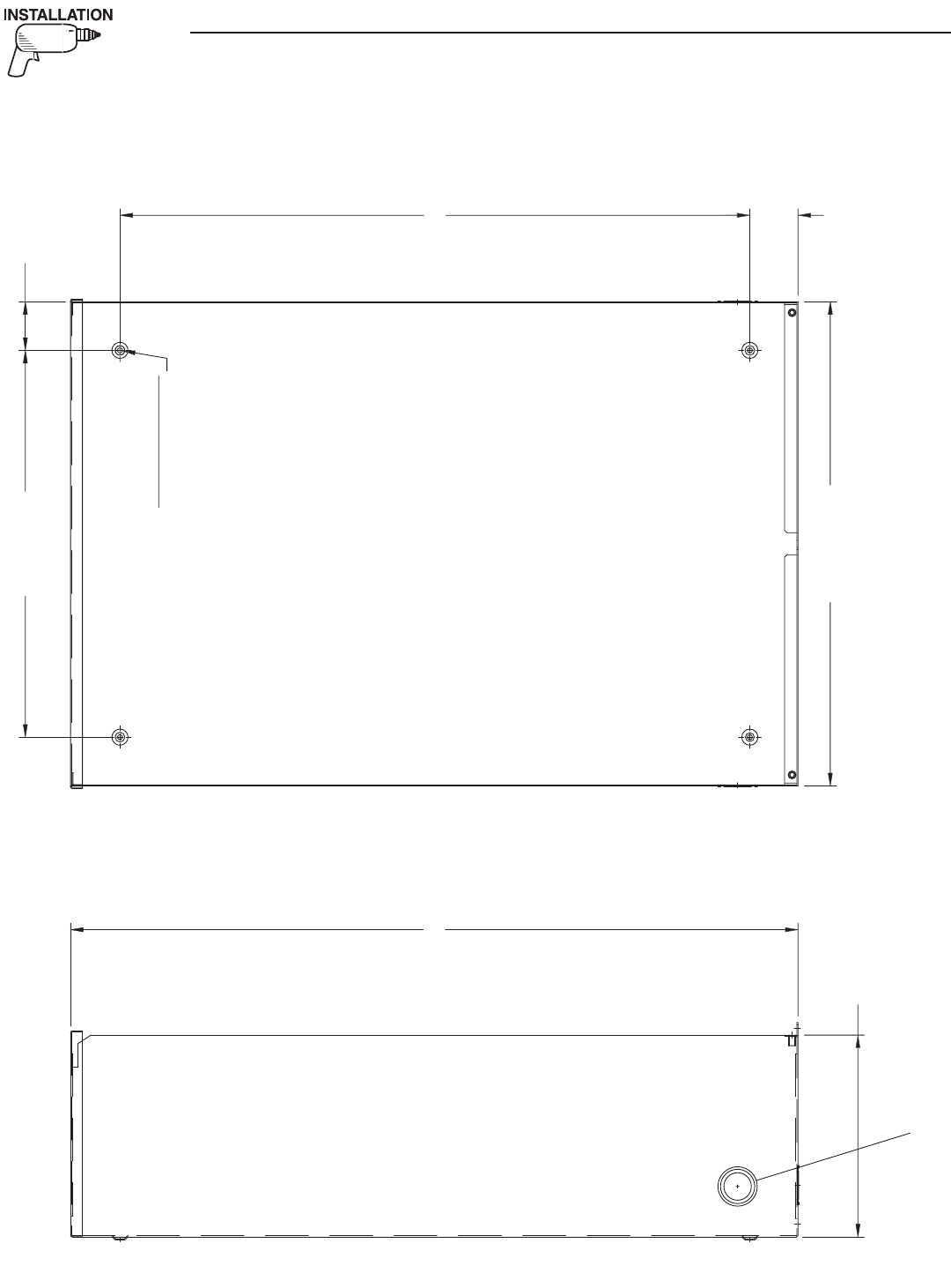
2.3 MOUNTING
Mounting dimensions for the transfer switch enclo-
sure are in this manual. Enclosures are typically wall-
mounted. See the “Mounting Dimensions” drawing.
Handle transfer switches carefully when install-
ing. Do not drop the switch. Protect the switch
against impact at all times, and against construc-
tion grit and metal chips. Never install a transfer
switch that has been damaged.
Install the transfer switch as close as possible to the
electrical loads that are to be connected to it. Mount
the switch vertically to a rigid supporting structure.
To prevent switch distortion, level all mounting
points. If necessary, use washers behind mounting
holes to level the unit.
2.4 CONNECTING POWER SOURCE
AND LOAD LINES
DANGER
Make sure to turn OFF both the UTILITY
(Normal) and EMERGENCY (Standby generator)
power supplies before trying to connect power
source and load lines to the transfer switch.
Supply voltages are extremely high and danger-
ous. Contact with such high voltage power sup-
ply lines causes extremely hazardous, possibly
lethal, electrical shock.
Wiring diagrams and electrical schematics are pro-
vided in this manual. Power source and load connec-
tions are made at the transfer mechanism, inside the
switch enclosure.
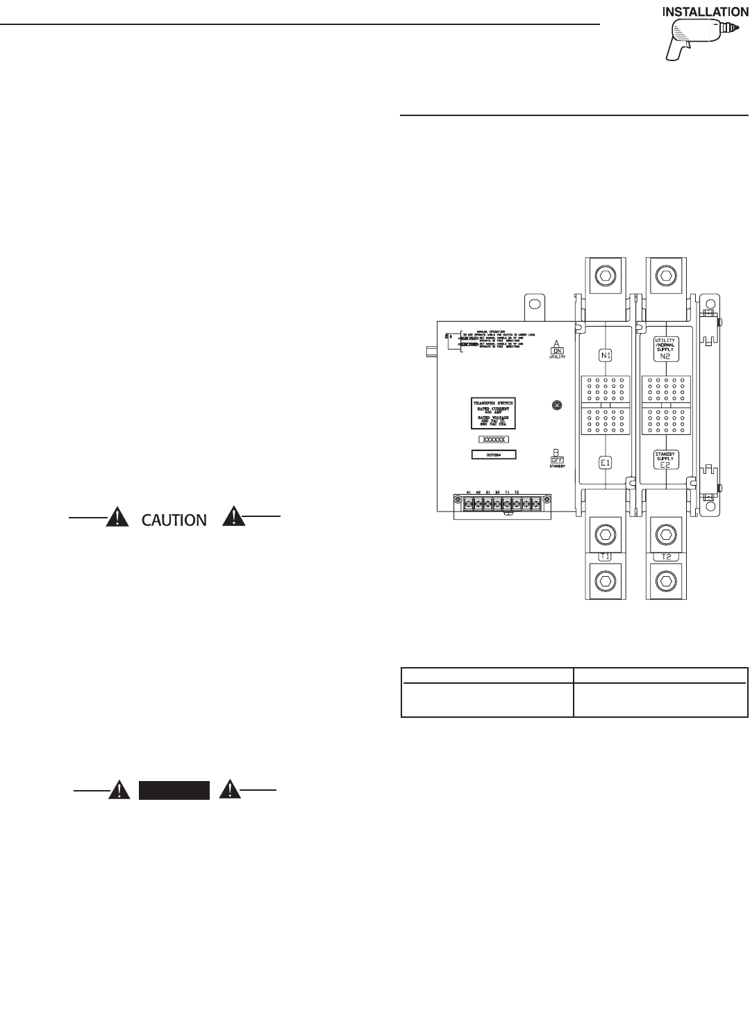
2.4.1 2-POLE MECHANISM
These switches (Figure 2.1) are used with a single
phase system, when the single phase NEUTRAL line
is to be connected to a Neutral Lug and is not to be
switched.
Figure 2.1 — Typical 2-Pole Transfer Mechanism
(400 Amp Shown)
Solderless, screw-type terminal lugs are standard.
The conductor size range is as follows:
Conductor sizes must be adequate to handle the max-
imum current to which they will be subjected; based
on the 75°C column of tables, charts, etc. used to size
conductors. The installation must comply fully with
all applicable codes, standards and regulations.
Before connecting wiring cables to terminals, remove
any surface oxides from the cable ends with a wire
brush. All power cables should enter the switch next
to transfer mechanism terminals. If ALUMINUM con-
ductors are used, apply corrosion inhibitor to con-
ductors. Tighten terminal lugs to the torque values as
noted on the decal located on the inside of the door.
After tightening terminal lugs, carefully wipe away
any excess corrosion inhibitor.
All power cables should enter the switch next to the
transfer mechanism terminals.
Section 2 — Installation
RTS “W” Type Transfer Switch
Switch Rating Wire Range
400A (1) #4-600 MCM or
(2) 1/0-250 MCM
4
Use a torque wrench to tighten the conductors,
being sure not to overtighten, or damage to
the switch base could occur. If undertightened,
a loose connection would result, causing excess
heat which could damage the switch base.
Connect power source load conductors to clearly
marked transfer mechanism terminal lugs as fol-
lows
1. Connect UTILITY (NORMAL) power source cables
to switch terminals N1, N2, (N3).
2. Connect EMERGENCY (STANDBY) source power
cables to transfer switch terminals E1, E2, (E3).
3. Connect customer LOAD leads to switch termi-
nals T1, T2, (T3).
4. Connect neutral conductors of UTILITY,
EMERGENCY and customer LOAD to the neutral
block.
Conductors must be properly supported, of approved
insulative qualities, protected by approved conduit,
and of the correct wire gauge size in accordance with
applicable codes.
Be sure to maintain proper electrical clearance
between live metal parts and grounded metal. Allow
at least 1/2 inch for 100-400 amp circuits.
2.5 CONNECTING START CIRCUIT
WIRES
Control system interconnections consist of UTILITY
1 and 2, and leads 23 and 194. Control system
interconnection leads must be run in a conduit that
is separate from the AC power lead. Recommended
wire gauge sizes for this wiring depends on the length
of the wire, as recommended below:
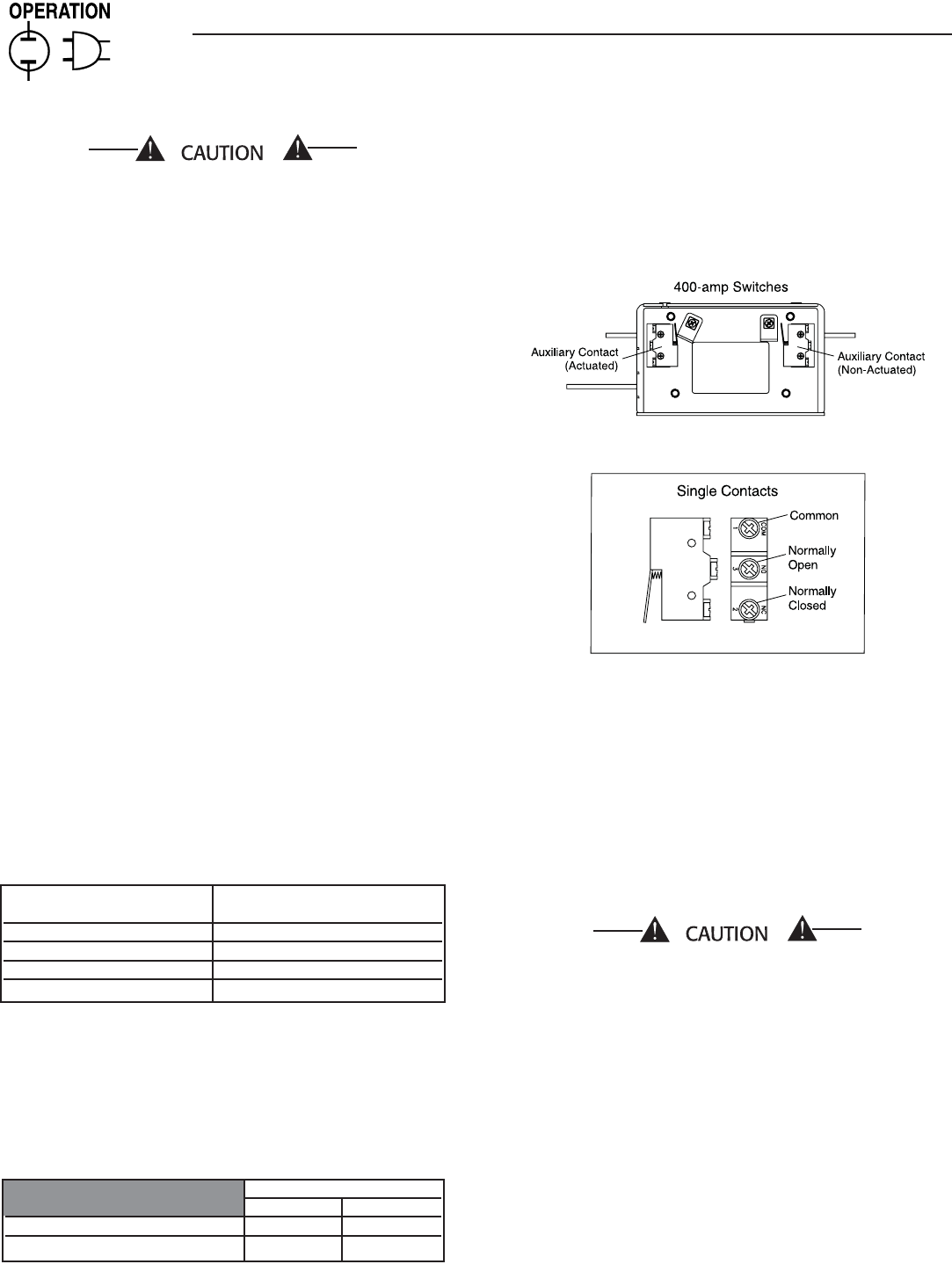
2.6 AUXILIARY CONTACTS
If desired, there are Auxiliary Contacts on the transfer
switch to operate customer accessories, remote advi-
sory lights, or remote annunciator devices. A suitable
power source must be connected to the COMMON (C)
terminal. See Figure 2.3.
Contact operation is shown in the following chart:
NOTE:
Auxiliary Contacts are rated 10 amps at 125 or
250 volts AC. DO NOT EXCEED THE RATED
VOLTAGE AND CURRENT OF THE CONTACTS.
Figure 2.3 – Auxiliary Contacts
Side views shown in Utility position
3.1 FUNCTIONAL TESTS AND
ADJUSTMENTS
Following transfer switch installation and intercon-
nection, inspect the entire installation carefully. A
competent, qualified electrician should inspect it.
The installation should comply strictly with all appli-
cable codes, standards, and regulations. When abso-
lutely certain the installation is proper and correct,
complete a functional test of the system.
Perform functional tests in the exact order pre-
sented in this manual, or damage to the switch
could be done.
IMPORTANT: Before proceeding with functional tests,
read and make sure you understand all instructions
and information in this section. Also read the infor-
mation and instructions of labels and decals affixed
to the switch. Note any options or accessories that
might be installed and review their operation.
MAXIMUM WIRE LENGTH RECOMMENDED WIRE
SIZE
460 feet (140m) No. 18 AWG.
461 to 730 feet (223m) No. 16 AWG.
731 to 1,160 feet (354m) No. 14 AWG.
1,161 to 1,850 feet (565m) No. 12 AWG.
Switch Position
Utility Standby
Common to Normally Open Open Closed
Common to Normally Closed Closed Open
Section 3 — Operation
RTS “W” Type Transfer Switch
5
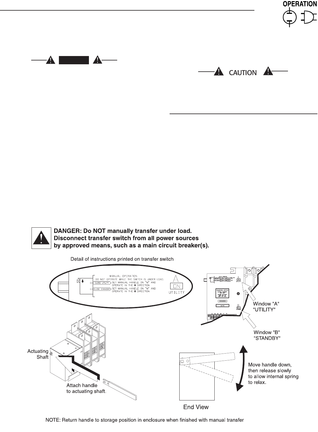
3.2 MANUAL OPERATION
DANGER
Do NOT manually transfer under load.
Disconnect transfer switch from all power sourc-
es by approved means, such as a main circuit
breaker(s).
A manual HANDLE is shipped with the transfer
switch. Manual operation must be checked BEFORE
the transfer switch is operated electrically. To check
manual operation, proceed as follows:
1. Turn the generator’s AUTO/OFF/MANUAL switch
to OFF.
2. Turn OFF both UTILITY and EMERGENCY power
supplies to the transfer switch, with whatever
means provided (such as the main line circuit
breakers).
3. Note position of transfer mechanism main con-
tacts by observing display windows in “A” and “B”
in Figure 3.1 on page 6 as follows:
• Window “A” ON, Window “B” OFF - LOAD termi-
nals (T1, T2, T3) are connected to utility termi-
nals (N1, N2, N3).
• Window “A” OFF, Window “B” ON - LOAD termi-
nals (T1, T2, T3) are connected to emergency
terminals (E1, E2, E3).
Do not use excessive force when operating the
transfer switch manually or the manual handle
could be damaged.
3.2.1 CLOSE TO NORMAL SOURCE SIDE
Before proceeding, verify the position of the switch
by observing window “A” in Figure 3.1. If window “A”
reads “ON”, the contacts are closed in the normal
position, no further action is required. If it reads
“OFF”, proceed with Step 1.
Step 1: With the handle attached to the actuating
shaft, move handle in the direction of the
arrow on the switch cover until it stops
— DO NOT FORCE. Release handle slowly
to allow the spring in the switch box to relax.
“ON” now appears in Window “A” and “OFF”
appears in Window “B”.
Section 3 — Operation
RTS “W” Type Transfer Switch
Figure 3.1 — Actuating Transfer Switch
6
3.2.2 CLOSE TO EMERGENCY SOURCE SIDE
Before proceeding, verify the position of the switch
by observing window “B” in Figure 3.1. If window
“B” reads “ON”, the contacts are closed in the
EMERGENCY (STANDBY) position. No further action
is required. If it reads “OFF”, proceed with Step 1.
Step 1: With the handle attached to the actuating
shaft, move the handle in the direction of the
arrow on the switch cover until it stops - DO
NOT FORCE. Release handle slowly to allow
the spring in the switch box to relax. “OFF”
now appears in Window “A” and “ON” appears
in Window “B”.
3.2.3 RETURN TO NORMAL SOURCE SIDE
Manually actuate switch to return Window “A” to the
“ON” position.
3.3 VOLTAGE CHECKS
3.3.1 UTILITY VOLTAGE CHECKS
1. Turn ON the UTILITY power supply to the trans-
fer switch with whatever means provided (such as
the UTILITY maim line circuit breaker).
DANGER
PROCEED WITH CAUTION. THE TRANSFER
SWITCH IS NOW ELECTRICALLY HOT. CONTACT
WITH LIVE TERMINALS RESULTS IN EXTREMELY
HAZARDOUS AND POSSIBLY FATAL ELECTRICAL
SHOCK.
2. With an accurate AC voltmeter, check for correct
voltage.
Single-phase utility supply:
Measure across ATS terminal lugs N1 and N2; N1
to NEUTRAL and N2 to NEUTRAL.
DANGER
FAILURE TO TURN OFF THE UTILITY SUPPLY
BEFORE WORKING ON THE UTILITY CONNEC-
TIONS OF THE ATS WILL RESULT IN EXTREMELY
DANGEROUS AND POSSIBLY FATAL ELECTRICAL
SHOCK.
5. When certain that UTILITY supply voltage is cor-
rect and compatible with transfer switch ratings,
turn OFF the UTILITY supply to the transfer
switch.
3.3.2 GENERATOR VOLTAGE CHECKS
1. On the generator panel, set the AUTO/OFF/
MANUAL switch to MANUAL position. The gen-
erator should crank and start.
2. Let the generator stabilize and warm up at no-
load for at least five minutes.
3. Set the generator's main circuit breaker (CB1) to
its ON or CLOSED position.
DANGER
PROCEED WITH CAUTION. GENERATOR
OUTPUT VOLTAGE IS NOW BEING DELIVERED
TO TRANSFER SWITCH TERMINALS. CONTACT
WITH LIVE TERMINALS RESULTS IN EXTREMELY
DANGEROUS AND POSSIBLY FATAL ELECTRICAL
SHOCK.
4. With an accurate AC voltmeter and frequency
meter, check the no-load, voltage and frequency.
Single-phase generator supply:
Measure across ATS terminal lugs E1 to E2; E1
to NEUTRAL and E2 to NEUTRAL.
a. Frequency ....................................... 60-62 Hz
b. Terminals E1 to E2 ........................ 240-246 VAC
c. Terminals E1 to NEUTRAL ............. 120-123 VAC
d. Terminals E2 to NEUTRAL ............. 120-123 VAC
5. When certain that UTILITY supply voltage is cor-
rect and compatible with transfer switch ratings,
turn OFF the UTILITY supply to the transfer
switch.
6. Set the generator’s main circuit breaker (CB1) to
its OFF or OPEN position.
7. Set the AUTO/OFF/MANUAL switch to the OFF
position to shut down the generator.
NOTE:
Do NOT proceed until generator AC output volt-
age and frequency are correct and within stated
limits. If the no-load voltage is correct but no-
load frequency is incorrect, the engine governed
speed probably requires adjustment. If no-load
frequency is correct but voltage is not, the voltage
regulator may require adjustment.
Section 3 — Operation
RTS “W” Type Transfer Switch

7
3.4 GENERATOR TESTS UNDER LOAD
1. Set the generator's main circuit breaker to its
OFF or OPEN position.
2. Manually actuate the transfer switch main con-
tacts to their EMERGENCY (STANDBY) position.
Refer to “Manual Operation” section.
3. To start the generator, set the AUTO/OFF/MANUAL
switch to MANUAL. When engine starts, let it sta-
bilize for a few minutes.
4. Turn the generator's main circuit breaker to the
ON or CLOSED position. The generator now pow-
ers all LOAD circuits. Check generator operation
under load as follows:
• Turn ON electrical loads to the full rated watt-
age/amperage capacity of the generator. DO
NOT OVERLOAD.
• With maximum rated load applied, check
voltage and frequency across transfer switch
terminals E1 and E2. Voltage should be
greater than 200 volts (208VAC system) or
230 volts (240VAC system); frequency should
be greater than 59 Hz.
• Let the generator run under rated load for at
least 30 minutes. With unit running, listen for
unusual noises, vibration, overheating, etc.,
that might indicate a problem.
5. When checkout under load is complete, set main
circuit breaker of the generator to the OFF or
OPEN position.
6. Let the generator run at no-load for several min-
utes. Then, shut down by setting the AUTO/OFF/
MANUAL switch to its OFF position.
7. Move the switch's main contacts back to the
UTILITY position. For example, load connected to
utility power supply. Refer to “Manual Operation”.
Handle and operating lever of transfer switch
should be in down position.
8. Turn on the utility power supply to transfer
switch, using whatever means provided (such
as a utility main line circuit breaker). The utility
power source now powers the loads.
9. Set the generator's AUTO/OFF/MANUAL switch to
its AUTO position. The system is now set for fully
automatic operation.
Section 3 — Operation
RTS “W” Type Transfer Switch
8
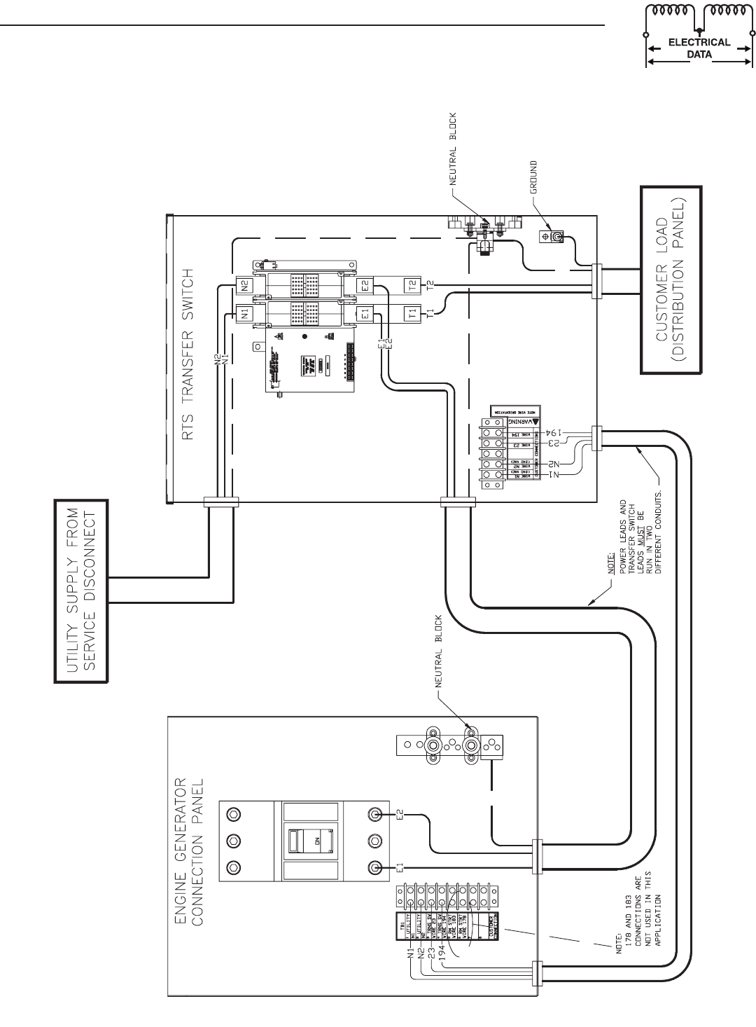
Section 4 — Installation Diagram
RTS “W” Type Transfer Switch
Installation Diagram – Drawing No. 0F6401
6
09.6mm
[
24.0"
]
9
17mm
[
36.1"
]
T
RIPLE EK
O
SU
ITABLE
FOR 1"
,
1.25" & 1.50" CONDUIT
3
PLA
C
E
S
2
54mm
[
10.0"
]
7
94mm
[
31.3"
]
6
0.8mm
[
2.4"
]
6
1.3mm
[
2.4"
]
4
87mm
[
19.2"
]
MOU
NTIN
G
H
O
LE
S
:
Ø
6
.35mm
[
Ø
0
.25"
]
4
-PLA
C
E
S
9
Section 5 — Electrical Data
RTS “W” Type Transfer Switch
Interconnection Diagram - Drawing No. 0G1944
B2
A2
B1
A1
C
6
9
TR
1
7
TR
E1
E1
N2A
N2A
N1A
E2
2
05
12
6
TR
2
3
1
94
2
3
1
94
N2A
LE
G
EN
D
G
T
S
N
O
TE
S:
A
LL
CO
NTA
C
T
S
S
H
O
WN WIT
H
TRAN
S
FER
S
WIT
C
H IN
U
TILIT
Y
P
OS
ITI
O
N
.
B
A
WHITE
RED
L
S2
L
S3
L
S1
T
1
T2
2
3
5
6
1
4
C
-
CO
NTA
C
T
O
R A
C
T
U
ATIN
G
CO
I
L
G
T
S
- TRAN
S
FER
S
WIT
C
H
CO
NTA
C
T
OR
LS1
,
LS2
,
LS3 - LIMIT SWITCHES
,
ACTUATO
R
TR - RELAY
,
TRANSFE
R
TS - TERMINAL STRIP
(
CUSTOMER CONNECTION
)
N1A
F2
N2
N1
F1
N1A
N2A
12
6
F1
,
F2 - FUSE 5A SENSIN
G
10
Section 5 — Electrical Data
RTS “W” Type Transfer Switch
Wiring Diagram/Schematic – Drawing No. 0D3819-A
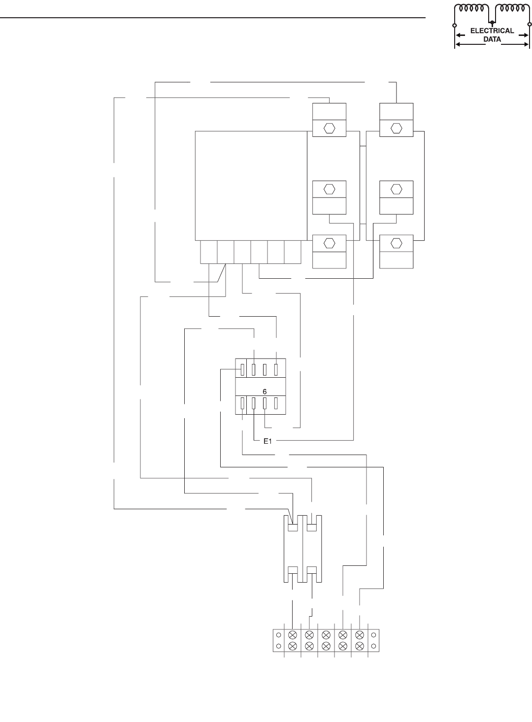
11
TR
G
T
S
T1
E1
N1
T2
E2
N2
B1
B2
A2
A1
N1A
N1A
12
6
E2
E1
N2A
2
05
N1A
2
05
E1
E1
A
7
1
B
9
3
T1
T2
N1A
N2A
12
6
2
05
N1A
N1A
N1A
N1A
F2
F1
23
19
4
T
S
U
TILITY 2
U
TILITY 1
1
94
2
3
2
3
1
94
2
3
1
94
N1
N2
N2A
N2A
N2A
N2A
N2A
N2A
N1A
2
3
1
94
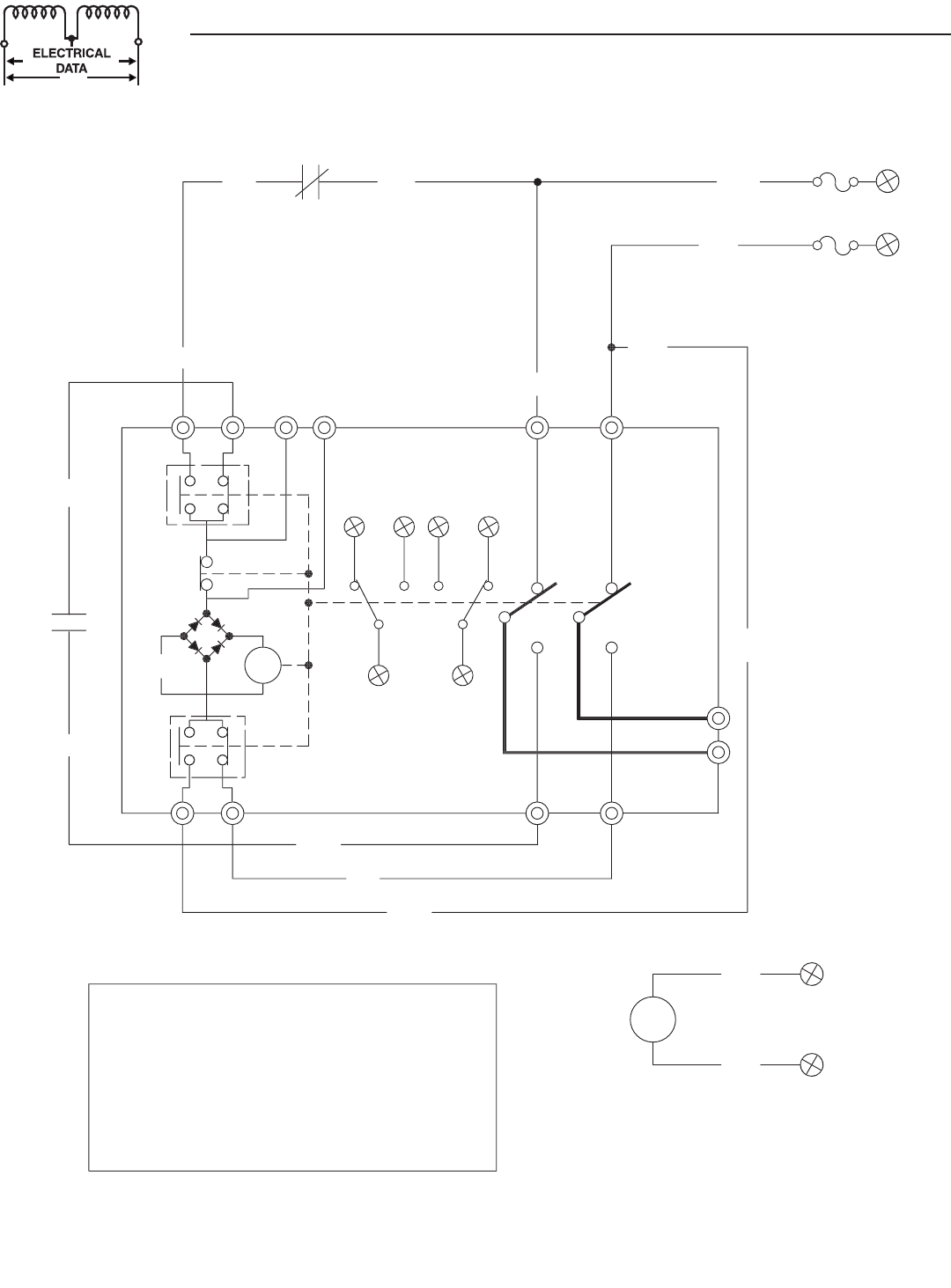
Section 5 — Electrical Data
RTS “W” Type Transfer Switch
Wiring Diagram/Schematic – Drawing No. 0D3819-A
12
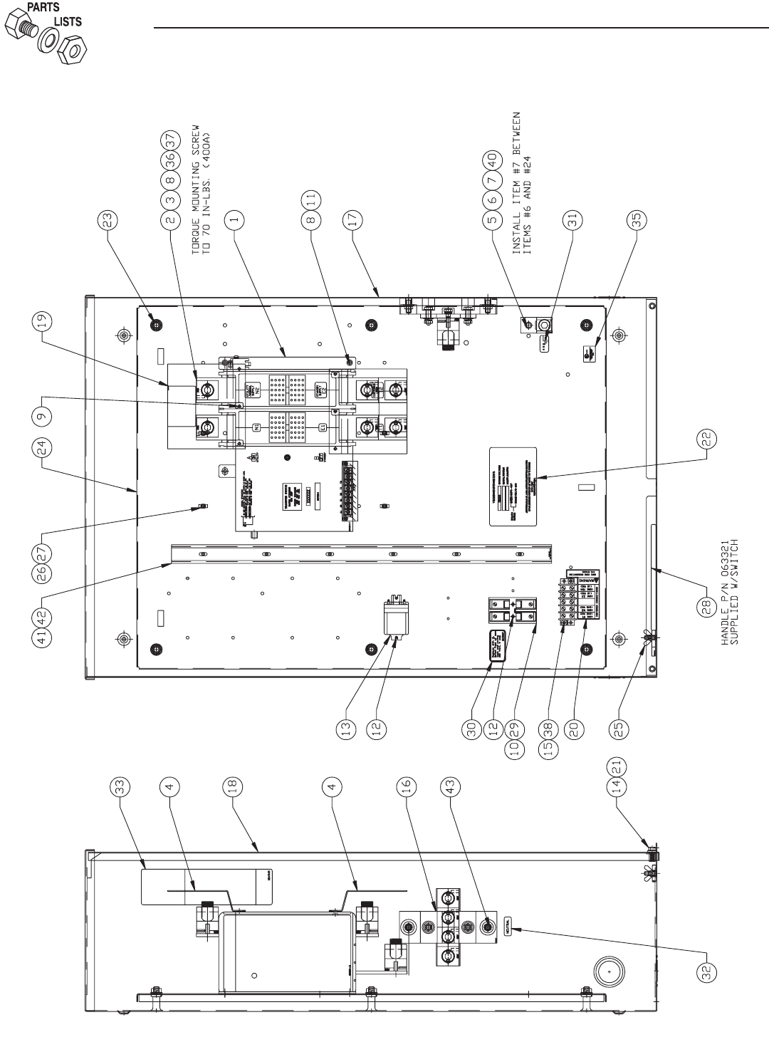
Section 6 — Exploded Views and Parts List
RTS “W” Type Transfer Switch
400 A Switch Assembly – Drawing No. 0G1510$

13
Section 6 — Exploded Views and Parts List
RTS “W” Type Transfer Switch
400 A Switch Assembly – Drawing No. 0G1510$
ITEM PART NO. QTY. DESCRIPTION
1 0D7294 1 XFER SW-W 400A600V2P
2 0A7822 6 LUG, SLDLSS 600/250-1/0X1/4-28
3 026902 5 SCREW TAPTITE #8-32X1/4 BP
4 0C7907J 2 COVER LUG 2P 400AMP
5 024526 1 SCREW HHTT 5/16-18 X 3/4 CZ
6 057329 1 LUG, SOLDERLESS 350-#6X13/32 AL/CU
7 027482 1 WASHER SHAKEPROOF EXT 5/16 STEEL
8 022097 9 WASHER LOCK M6-1/4
9 0C8275 4 SCREW PPHM DSEMS M4-.7 X 10 ZNC
(2) 10 0D2806 1 FUSEBLOCK 30A 600V 2POS W/SQ
11 090388 3 SCREW TAPTITE M6-1.0 X 12 MM
12 0A1495 6 SCREW TAPTITE M4-.7 X 10 MM
(2) 13 063617 1 RELAY PNL 12VDC DPDT 10A@240VA
14 047411 2 SCREW HHC M6-1.0 X 16 G8.8
15 0A1661 2 RIVET, POP
16 0F4034 1 ASSY. NEUTRAL BLOCK 300/400A
17 0F5935 1 RTS 3R ENCLOSURE 24X36X10
18 0F5939 1 COVER TRANSFER SWITCH
19 0C8308 2 DECAL TERMINAL SHOCK HAZARD
20 0C2262 1 DECAL TERMINAL STRIP
21 0F6165 2 WASHER, NYLON
22 0G1520 1 DECAL,DATA XFER SW 400A,240V
23 064101 6 NUT HEX FL WHIZ 3/8-16
24 0F5940 1 SUBPLATE,100A TS 3R 480V
25 087680 1 NUT WING M6-1.0
26 063378 4 HOLDER CABLE TIE
27 064761 4 TIE WRAP UL 5.6" X .10" NATL
28 063321 1 HANDLE TRANSFER SWITCH 1-400A
29 073590A 2 FUSE 5A X BSS HLDR73591
30 0D3587 1 DECAL,FUSE REPLACEMENT
31 067210A 1 DECAL GROUND LUG
32 0A9457 1 DECAL NEUTRAL
33 0D4545 1 DECAL MANUAL OPERATION
(1) 34 0F6129 1 DECAL, TEST SEQUENCE
35 081221 1 DECAL, UL NAMEPLATE
36 0A8261 6 SCREW, HHCS 1/4-28 X 5/8"
37 022473 6 WASHER, FLAT 1/4-6M ZINC
(2) 38 048850 1 BLOCK TERM 20A 5 X 6 X 1100V
39 0F6273A 1 HARNESS 400A 2 POLE RTS (NOT SHOWN)
40 022129 1 WASHER LOCK M8-5/16
41 091472 2' DUCT WIRING 1X1.5
42 091472A 2' COVER WIRE DUCT 1 IN
43 067989 2 NUT HEX FL WHIZ M8-1.25
(1) CENTER DECAL ON INSIDE OF THE COVER (ITEM #18)
(2) ITEMS INCLUDED WITH HARNESS

Section 8 — Warranty
RTS “W” Type Transfer Switch
CARRIER WARRANTY/SERVICE
Carrier will warrant that from the date of purchase, our transfer switch will be free from
defects in material and workmanship for the items and periods set forth in the warranty
statement found in the owners manual of the Carrier generator that this transfer switch
will be utilized with.
Any equipment that the purchaser/owner claims to be defective must be examined by the
nearest Carrier Dealer.
THIS WARRANTY IS IN PLACE OF ALL OTHER WARRANTIES, EXPRESSED OR
IMPLIED, SPECIFICALLY, CARRIER MAKES NO OTHER WARRANTIES AS TO THE
MERCHANTABILITY OR FITNESS FOR A PARTICULAR PURPOSE.
Some states do not allow limitations on how long an implied warranty lasts, so the above
limitation may not apply to you.
CARRIER’S ONLY LIABILITY SHALL BE THE REPAIR OR REPLACEMENT OF PART(S) AS
STATED ABOVE. IN NO EVENT SHALL CARRIER BE LIABLE FOR ANY INCIDENTAL, OR
CONSEQUENTIAL DAMAGES, EVEN IF SUCH DAMAGES ARE A DIRECT RESULT OF
CARRIER’S NEGLIGENCE.
Some states do not allow the exclusion or limitation of incidental or consequential dam-
ages, so the above limitations may not apply to you.
This warranty gives you specific legal rights. You also may have other rights that vary from
state to state.
Part No. 0G1622 Rev. A (12/15/06) Printed in U.S.A.Catalog No. OMKGATD,XNS400-03
