Ruckus Wireless R500 IEEE 802.11ac Access Point User Manual R500 Quick Setup Guide
Ruckus Wireless, Inc. IEEE 802.11ac Access Point R500 Quick Setup Guide
UserManual.wiki
>
Ruckus Wireless
>
R500 User Manual
Users Manual
Navigation menu
Upload a User Manual
Namespaces
Wiki Guide
HTML
PDF
Info
Views
User Manual
Discussion / Help
Navigation
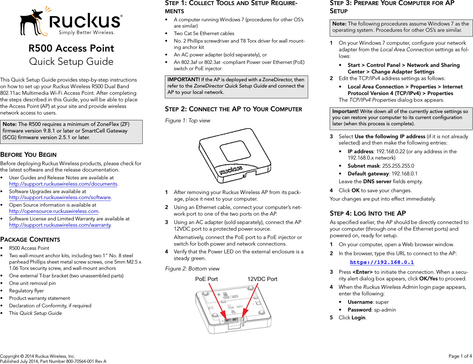
![Page 2 Professionally Installed Products The product is to be installed according to the installation instructions. The Use/Operator does not have access to the device once the device is installed and in use. Provisions for permanent grounding are provided. 1. Installation personal: This product is designed for specific application and needs to be installed by a qualified personal who has RF and related rule knowledge. The general user shall not attempt to install or change the setting. 2. Installation location: The product shall be installed at a location where the radiating antenna can be kept 20 cm from nearby person in normal operation condition to meet regulatory RF exposure requirement. Additionally, installation locations with 35km of Terminal Doppler Weather Radar locations shall follow instructions below. a. Any installation of either a master or a client device within 35 km of a TDWR location shall be separated by at least 30 MHz center-to-center) from the TDWR operating frequency. b. A voluntary WISPA sponsored database has been developed that allows operators and installers to register the location information of the UNII devices operating outdoors in the 5470 – 5725 MHz band within 35 km of any TDWR location (see http://www.spectrumbridge.com/udia/home.aspx ). This database may be used by government agencies in order to expedite resolution of any interference to TDWRs. c. Addition information can be obtained from the FCC Knowledge Database, Publication Number 443999. https://apps.fcc.gov/oetcf/kdb/index.cfm 3. External antenna: Use only the antennas which have been approved by Ruckus Wireless. The non-approved antenna(s) may produce unwanted spurious or excessive RF transmitting power which may lead to the violation of FCC limit and is prohibited. 4. Installation procedure: Please refer to user’s manual for the detail. 5. Warning: Please carefully select the installation position and make sure that the final output power does not exceed the limit set force in US Rule CFR 47 part 15 section 15.247 & 15.407. The violation of the rule could lead to serious federal penalty. External Antenna Notice This radio transmitter has been approved by the FCC and Industry Canada to operate with the antenna types listed below with the maximum permissible gain and required antenna impedance for each antenna type indicated. Antenna types not included in this list, having a gain greater than the maximum gain indicated for that type, are strictly prohibited for use with this device. Le présent émetteur radio (identifier le dispositif par son numéro de certification ou son numéro de modèle s'il fait partie du matériel de catégorie I) a été approuvé par Industrie Canada pour fonctionner avec les types d'antenne énumérés ci-dessous et ayant un gain admissible maximal et l'impédance requise pour chaque type d'antenne. Les types d'antenne non inclus dans cette liste, ou dont le gain est supérieur au gain maximal indiqué, sont strictement interdits pour l'exploitation de l'émetteur. Model: ZoneFlex 7441 [ZF7441]: This device has been designed to operate with an antenna having maximum gain of 2dBi. Other antenna types or having greater gain are strictly prohibited for use with this device. The required antenna impedance is 50 ohms. Model: ZoneFlex 7372E [ZF7372E]: This device has been designed to operate with an antenna having maximum gain of 7dBi. Other antenna types or having greater gain are strictly prohibited for use with this device. The required antenna impedance is 50 ohms. Products intended to be powered by an external power supply: Caution –This product is intended to be supplied by a Listed Direct Plug-In Power Unit marked Class 2 or LPS (sub-clause 2.5 of standard EN 60950-1). Available Ruckus power supplies intended for product operation are identified in the product datasheet. The last two digits of the power supply part number represent the country code. For additional applicable power supplies/options, see user instructions and product datasheet. Australia Statement This device complies with the ACMA requirements for a Wi-Fi device namely Radio Communications (Low Impact Potential Devices) Class Licence 2000 Amd. 1:2007 and Radiocommunications (Compliance Labelling – Electromagnetic Radiation) Notice 2003. The equipment complies with the ACMA requirements for radiation exposure for a "general user/non-aware user". This equipment should be installed and operated with a minimum distance of 20 cm between the radiator and your body. This equipment complies with the Australian safety requirements and should only used with the specified power adapter according to the product datasheet. Brazil Statement For Brazil, those products are designed for specific application and needs to be installed by a qualified personal who has RF and related rule knowledge. Regarding the operation on range of 5150 MHz to 5350 MHz , the average output power of the equipments must be adjusted to the maximum limit of - 0,48 dBm and for 5470 MHz to 5725 MHz, the average output power of the equipments must be adjusted to the maximum limit of 6,44 dBm. Para o Brasil, esses produtos são projetados para aplicações específicas e necessidades a serem instalados por um pessoal qualificado que tenha conhecimento regra RF e afins.Em relação à operação em série de 5150 MHz a 5350 MHz, a potência média de saída dos equipamentos deve ser ajustado para o limite máximo de - 0,48 dBm e para 5470 MHz a 5725 MHz, a potência média de saída dos equipamentos deve ser ajustada ao limite máximo de 6,44 dBm. Taiwan Statement 本產品為5.25-5.35 GHz頻帶內操作之UNII設備, 僅限於室內使用 The frequency band 5250 – 5350 MHz is restricted to indoor use. 經型式認證合格之低功率射頻電機,非經許可,公司、商號或使用者均不得擅自變更頻率、加大功率或變更原設計之特性及功能。 低功率射頻電機之使用不得影響飛航安全及干擾合法通信;經發現有干擾現象時,應立即停用,並改善至無干擾時方得繼續使用。前項合法通信,指依電信法規定作業之無線電通信。低功率射頻電機須忍受合法通信或工業、科學及醫療用電波輻射性電機設備之干擾. The control, adjustment and on/off operation of this device does not violate the “Administrative regulations on low power radio waves radiated devices”. Any adjustments to the device should be carried out or be monitored by a specialist who has expertise on radio frequency devices. Replacement of components which may lead to the violation to the regulations is not allowed. Without permission granted by the NCC, any company, enterprise, or user is not allowed to change frequency, enhance transmitting power or alter original characteristic as well as performance to an approved low power radio-frequency devices. The low power radio-frequency device shall not influence aircraft security and interfere with legal](https://usermanual.wiki/Ruckus-Wireless/R500/User-Guide-2375538-Page-6.png)
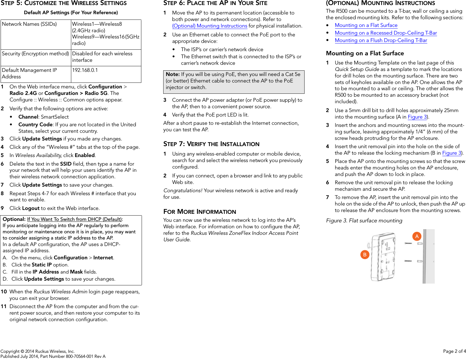
![Page 3 communications; if found, the user shall cease operating immediately until no interference is achieved. The said legal communications means radio communications is operated in compliance with the Telecommunications Act. The low power radio-frequency devices must not be susceptible with the interference from legal communications or ISM radio wave radiated devices. European Union Notices and National Restrictions The frequency band 5150 – 5350 MHz is restricted to indoor use Italy This product meets the National Radio Interface and the requirements specified in the National Frequency Allocation Table for Italy. Unless operating within the boundaries of the owner’s property, the use of this 2.4 GHz Wireless LAN product requires a ‘general authorization’. Please check with http://www.comunicazioni.it/ for more details. Questo prodotto è conforme alla specifiche di Interfaccia Radio Nazionali e rispetta il Piano Nazionale di ripartizione delle frequenze in Italia. Se non viene installato all’interno del proprio fondo, l’utilizzo di prodotti Wireless LAN a 2.4 GHz richiede una "Autorizzazione Generale". Consultare http://www.comunicazioni.it/ per maggiori dettagli. Belgium The Belgian Institute for Postal Services and Telecommunications (BIPT) must be notified of any outdoor wireless link having a range exceeding 300 meters. Please check http://www.bipt.be for more details. / Draadloze verbindingen voor buitengebruik en met een reikwijdte van meer dan 300 meter dienen aangemeld te worden bij het Belgisch Instituut voor postdiensten en telecommunicatie (BIPT). Zie http://www.bipt.be voor meer gegevens. / Les liaisons sans fil pour une utilisation en extérieur d’une distance supérieure à 300 mètres doivent être notifiées à l’Institut Belge des services Postaux et des Télécommunications (IBPT). Visitez http://www.ibpt.be pour de plus amples détails. Česky [Czech] Ruckus Wireless tímto prohlašuje, že tento Radio LAN je ve shodě se základními požadavky a dalšími příslušnými ustanoveními směrnice 1999/5/ES. Dansk [Danish] Undertegnede Ruckus Wireless erklærer herved, at følgende udstyr Radio LAN overholder de væsentlige krav og øvrige relevante krav i direktiv 1999/5/EF. Deutsch [German] Hiermit erklärt Ruckus Wireless, dass sich das Gerät Radio LAN in Übereinstimmung mit den grundlegenden Anforderungen und den übrigen einschlägigen Bestimmungen der Richtlinie 1999/5/EG befindet. Eesti [Estonian] Käesolevaga kinnitab Ruckus Wireless seadme Radio LAN vastavust direktiivi 1999/5/EÜ põhinõuetele ja nimetatud direktiivist tulenevatele teistele asjakohastele sätetele. English Hereby, Ruckus Wireless declares that this Radio LAN is in compliance with the essential requirements and other relevant provisions of Directive 1999/5/EC. Español [Spanish] Por medio de la presente Ruckus Wireless declara que el Radio LAN cumple con los requisitos esenciales y cualesquiera otras disposiciones aplicables o exigibles de la Directiva 1999/5/CE. Ελληνική [Greek] ΜΕ ΤΗΝ ΠΑΡΟΥΣΑ Ruckus Wireless ∆ΗΛΩΝΕΙ ΟΤΙ Radio LAN ΣΥΜΜΟΡΦΩΝΕΤΑΙ ΠΡΟΣ ΤΙΣ ΟΥΣΙΩ∆ΕΙΣ ΑΠΑΙΤΗΣΕΙΣ ΚΑΙ ΤΙΣ ΛΟΙΠΕΣ ΣΧΕΤΙΚΕΣ ∆ΙΑΤΑΞΕΙΣ ΤΗΣ Ο∆ΗΓΙΑΣ 1999/5/ΕΚ. Français [French] Par la présente Ruckus Wireless déclare que l'appareil Radio LAN est conforme aux exigences essentielles et aux autres dispositions pertinentes de la directive 1999/5/CE. Italiano [Italian] Con la presente Ruckus Wireless dichiara che questo Radio LAN è conforme ai requisiti essenziali ed alle altre disposizioni pertinenti stabilite dalla direttiva 1999/5/CE. Latviski [Latvian] Ar šo Ruckus Wireless deklarē, ka Radio LAN atbilst Direktīvas 1999/5/EK būtiskajām prasībām un citiem ar to saistītajiem noteikumiem. Lietuvių [Lithuanian] Šiuo Ruckus Wireless deklaruoja, kad šis Radio LAN atitinka esminius reikalavimus ir kitas 1999/5/EB Direktyvos nuostatas. Nederlands [Dutch] Hierbij verklaart Ruckus Wireless dat het toestel Radio LAN in overeenstemming is met de essentiële eisen en de andere relevante bepalingen van richtlijn 1999/5/EG. Malti [Maltese] Hawnhekk, Ruckus Wireless, jiddikjara li dan Radio LAN jikkonforma mal-ħtiġijiet essenzjali u ma provvedimenti oħrajn relevanti li hemm fid-Dirrettiva 1999/5/EC. Magyar [Hungarian] Alulírott, Ruckus Wireless nyilatkozom, hogy a Radio LAN megfelel a vonatkozó alapvetõ követelményeknek és az 1999/5/EC irányelv egyéb elõírásainak. Polski [Polish] Niniejszym Ruckus Wireless oświadcza, że Radio LAN jest zgodny z zasadniczymi wymogami oraz pozostałymi stosownymi postanowieniami Dyrektywy 1999/5/EC. Português [Portuguese] Ruckus Wireless declara que este Radio LAN está conforme com os requisitos essenciais e outras disposições da Directiva 1999/5/CE. Slovensko [Slovenian] Ruckus Wireless izjavlja, da je ta Radio LAN v skladu z bistvenimi zahtevami in ostalimi relevantnimi določili direktive 1999/5/ES. Slovensky [Slovak] Ruckus Wireless týmto vyhlasuje, že Radio LAN spĺňa základné požiadavky a všetky príslušné ustanovenia Smernice 1999/5/ES. AT FI IT PL GB RO BE FR LV PT IS TR CY DE LT SK LI CZ GR LU SI NO DK HU MT ES CH EE IE NL SE BG](https://usermanual.wiki/Ruckus-Wireless/R500/User-Guide-2375538-Page-7.png)
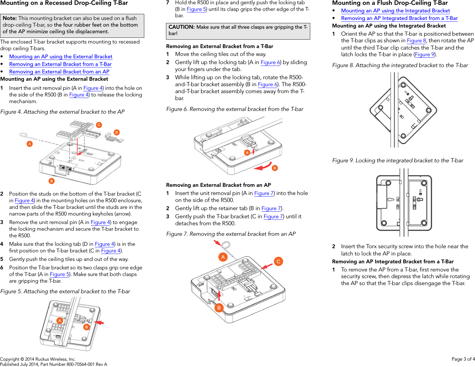
![Page 4 Suomi [Finnish] Ruckus Wireless vakuuttaa täten että Radio LAN tyyppinen laite on direktiivin 1999/5/EY oleellisten vaatimusten ja sitä koskevien direktiivin muiden ehtojen mukainen. Svenska [Swedish] Härmed intygar Ruckus Wireless att denna Radio LAN står I överensstämmelse med de väsentliga egenskapskrav och övriga relevanta bestämmelser som framgår av direktiv 1999/5/EG. Íslenska [Icelandic] Hér með lýsir Ruckus Wireless yfir því að Radio LAN er í samræmi við grunnkröfur og aðrar kröfur, sem gerðar eru í tilskipun 1999/5/EC. Norsk [Norwegian] Ruckus Wireless erklærer herved at utstyret Radio LAN er i samsvar med de grunnleggende krav og øvrige relevante krav i direktiv 1999/5/EF. 800-70402-002-G](https://usermanual.wiki/Ruckus-Wireless/R500/User-Guide-2375538-Page-8.png)