Ruckus Wireless T504 IEEE 802.11ac Access Point User Manual
Ruckus Wireless, Inc. IEEE 802.11ac Access Point Users Manual
UserManual.wiki
>
Ruckus Wireless
>
T504 User Manual
>
Users Manual
Contents
1.
Users Manual
2.
Regulatory Flyer
Users Manual
Navigation menu
Upload a User Manual
Namespaces
Wiki Guide
HTML
PDF
Info
Views
User Manual
Discussion / Help
Navigation
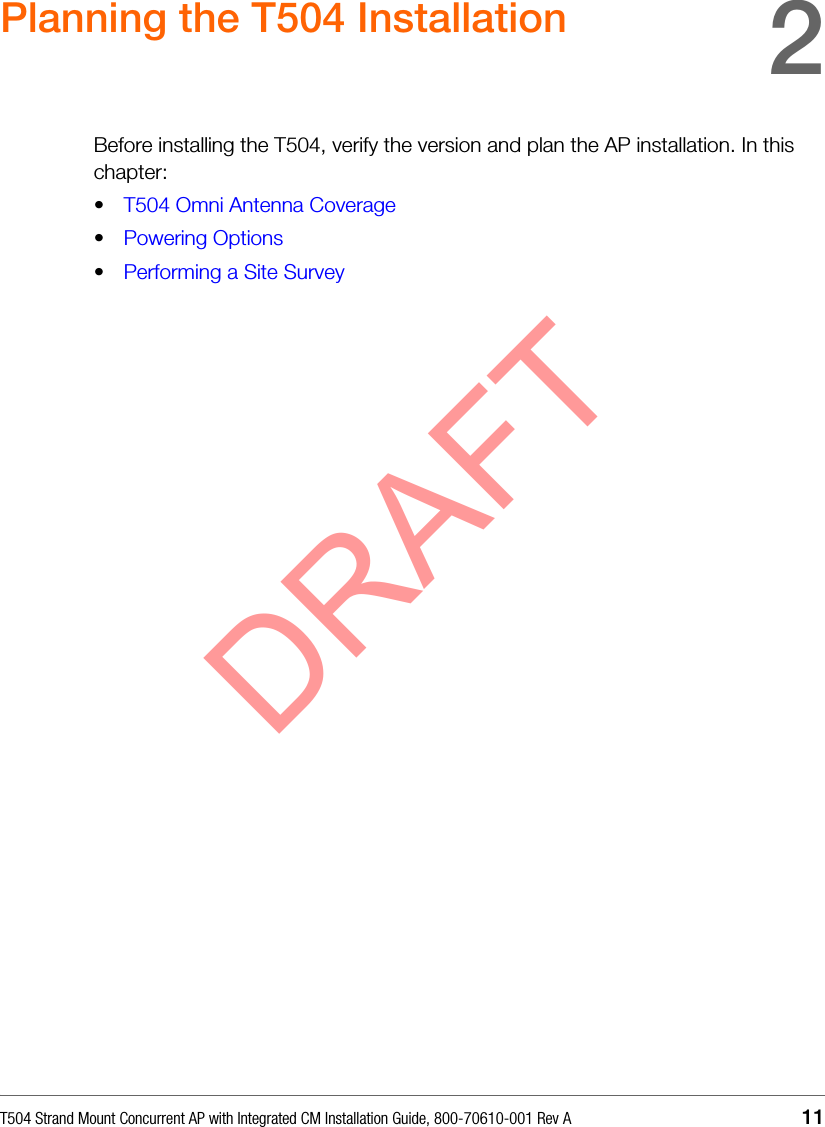
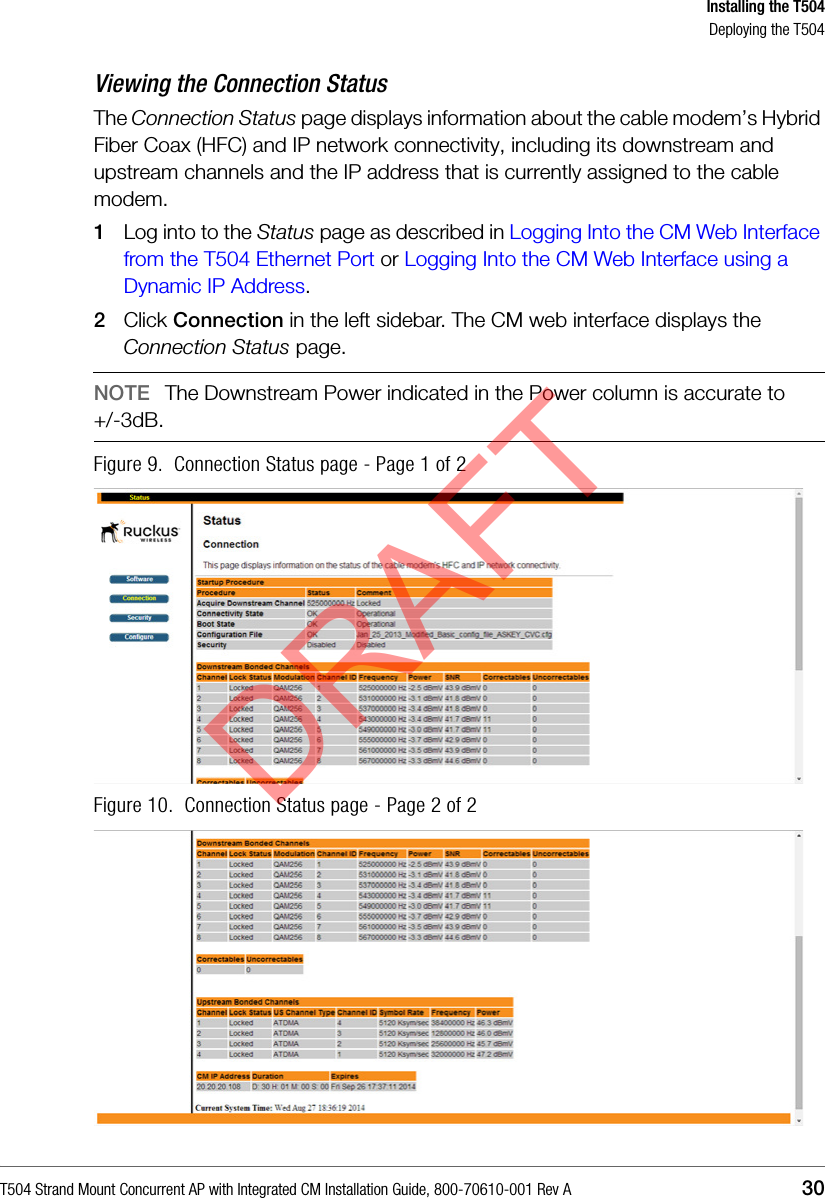
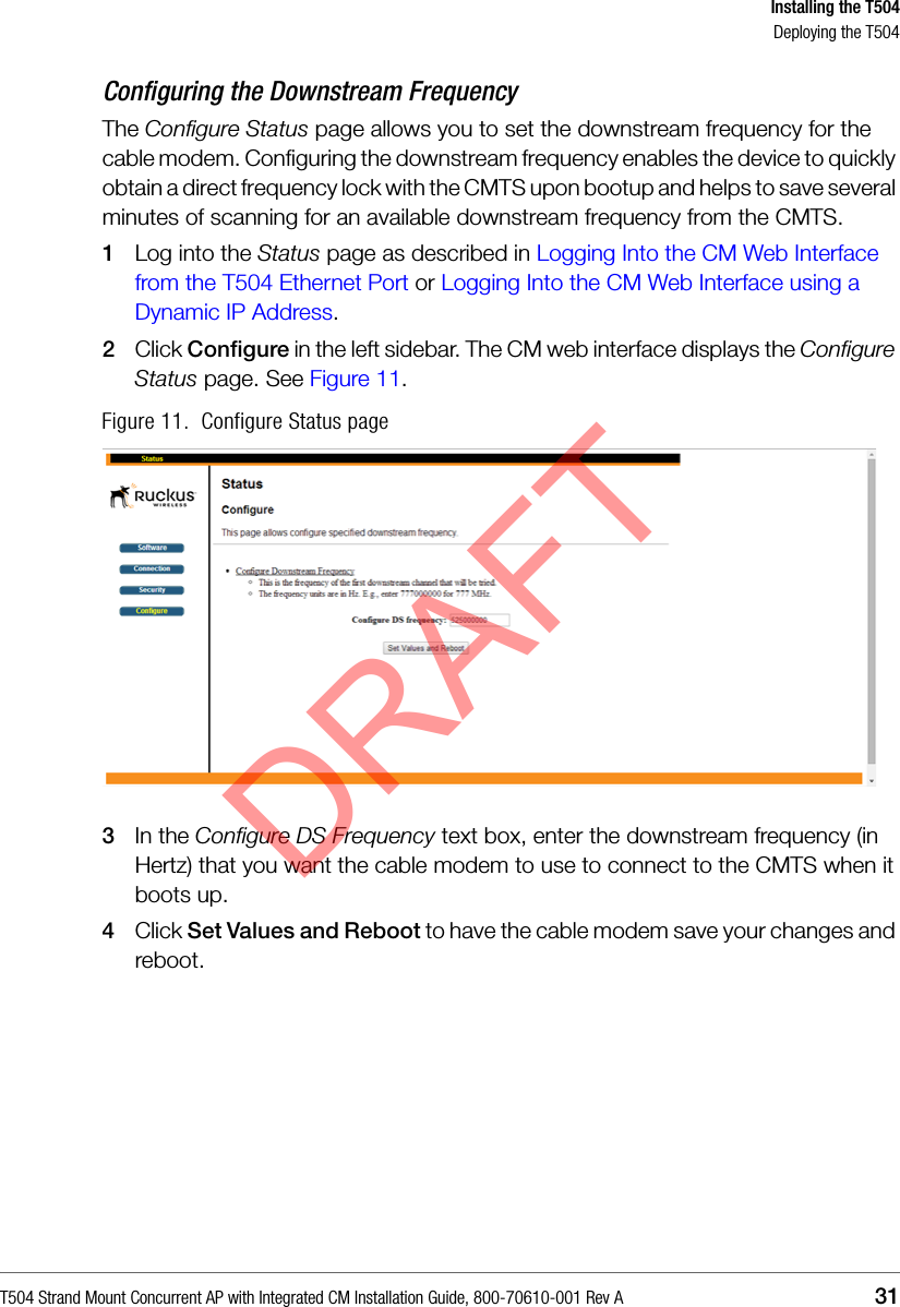
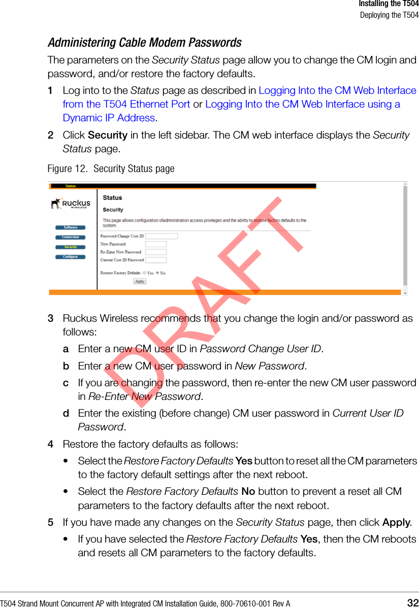
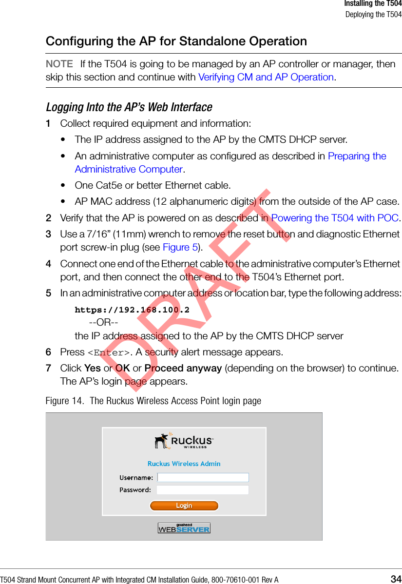
![Operating and Troubleshooting the T504How Radio Frequency Scanning WorksT504 Strand Mount Concurrent AP with Integrated CM Installation Guide, 800-70610-001 Rev A 40How Radio Frequency Scanning WorksThe following steps describe how a DOCSIS-compliant T504 performs radio frequency scanning:1Looks at the last “known good channel” (repeat this every 64 channel checks).2Checks the sixteen last known frequencies (repeat this every 32 channel checks).3Scans STD standard channels (where the center of the channel is an integer spaced by 6MHz), first [from 93MHz to 999MHz - 152 channels]).4Scans the harmonically related carrier (HRC) channels, which moves the channels 1.25MHz off the standard frequencies so the video carriers are all related by 6MHz [from 91.75 to 997.5MHz--152 channels].A complete frequency scan requires approximately 469 channel checks. Since each channel takes about 0.6 seconds, a full scan is done every 281 seconds (a little under 5 minutes).NOTE The scanning of generic DOCSIS channels is required the first time the T504 connects to an MSO. After the initial scan, the T504 is able to retrieve the local country frequency plan without a complete scan during its normal operation.DRAFT](https://usermanual.wiki/Ruckus-Wireless/T504.Users-Manual/User-Guide-2539027-Page-39.png)
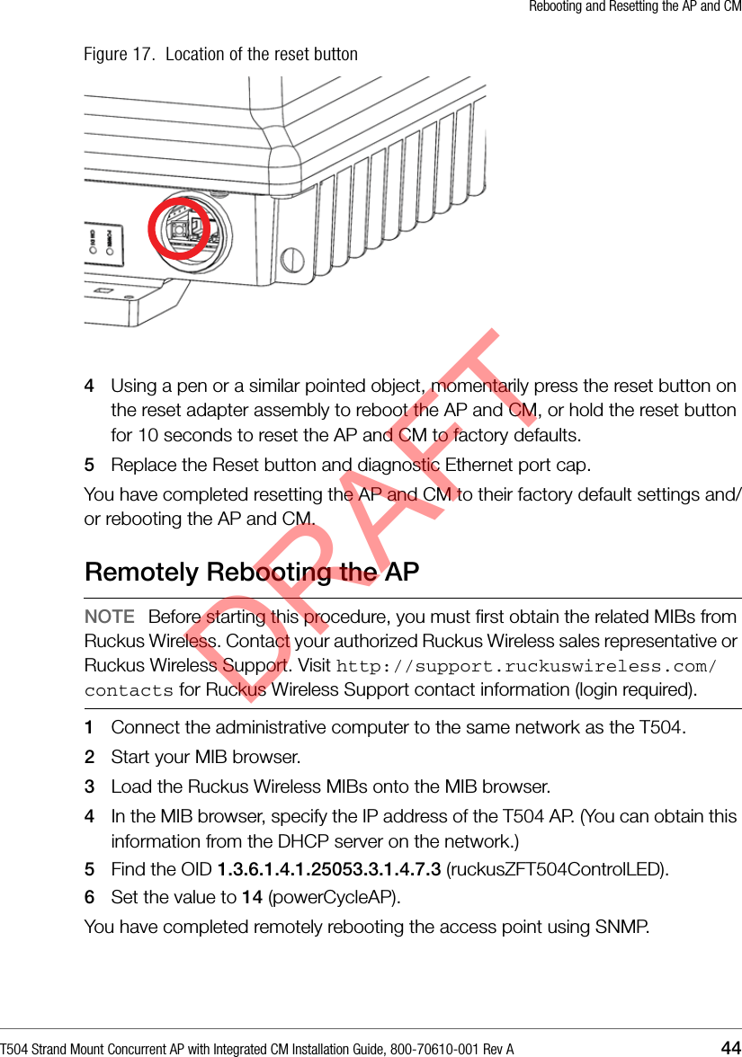
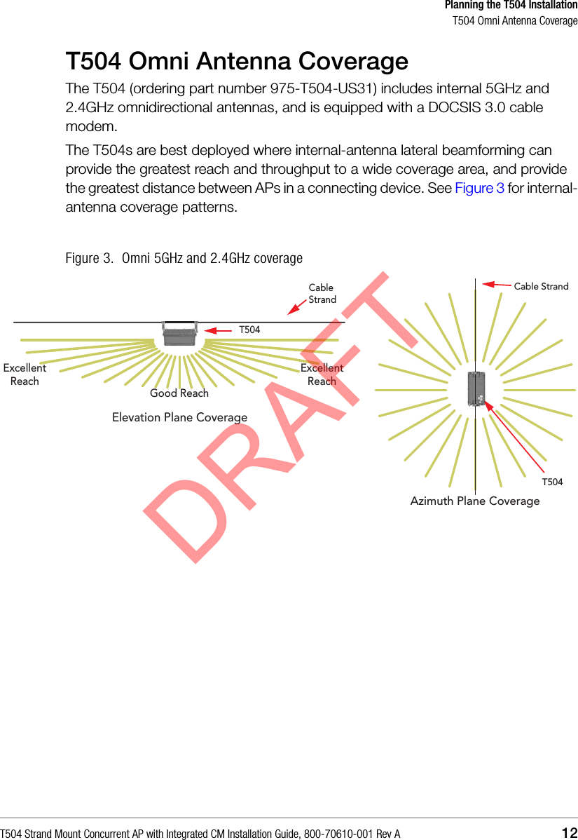
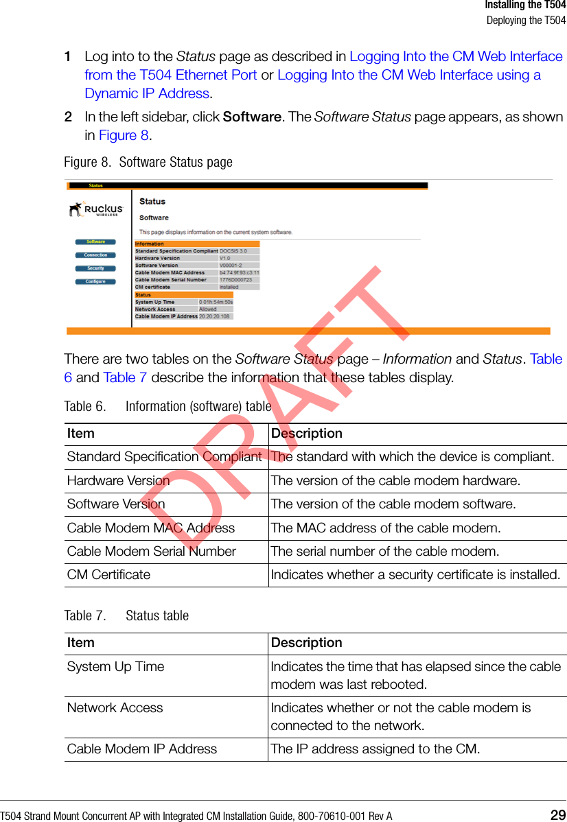
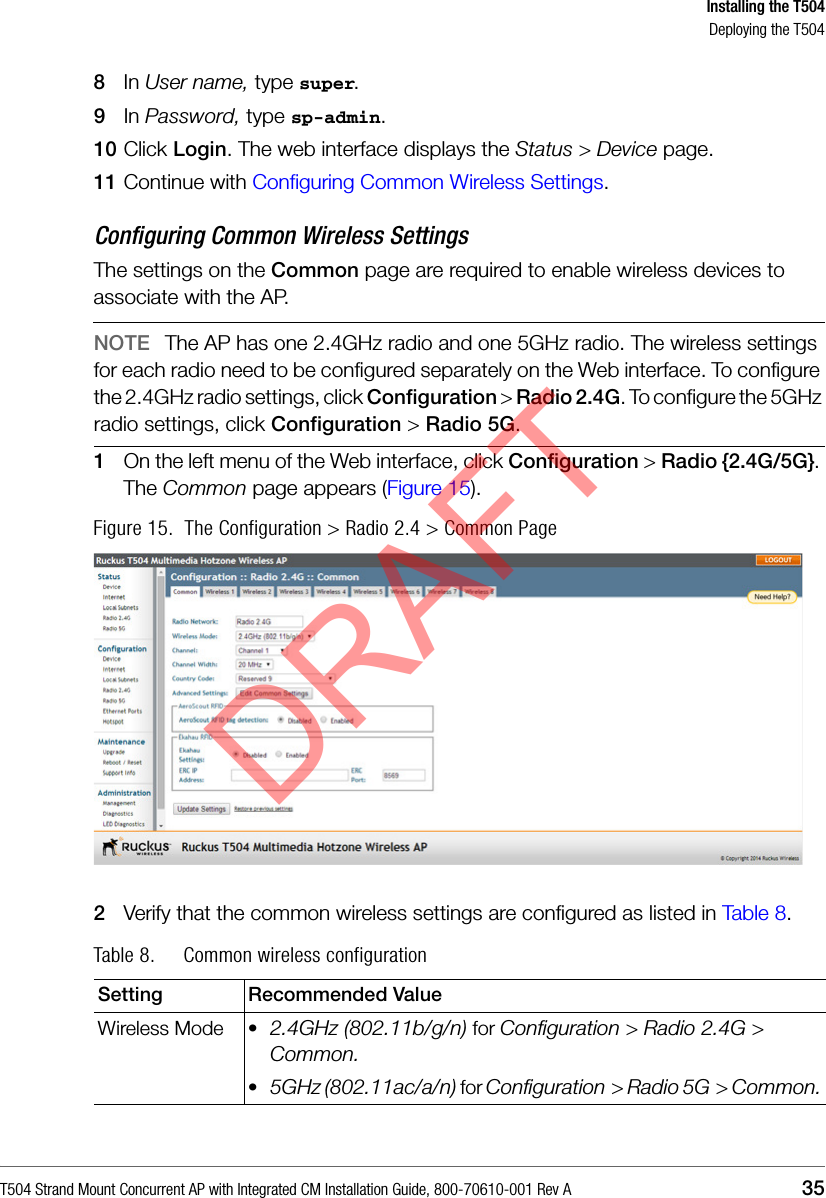
![T504 Strand Mount Concurrent AP with Integrated CM Installation Guide, 800-70610-001 Rev A 46CAppendix C: T504 Mounting Dimensions and WeightDimensionsFigure 18. T504 length--all dimensions in millimeters and [inches]DRAFT](https://usermanual.wiki/Ruckus-Wireless/T504.Users-Manual/User-Guide-2539027-Page-45.png)
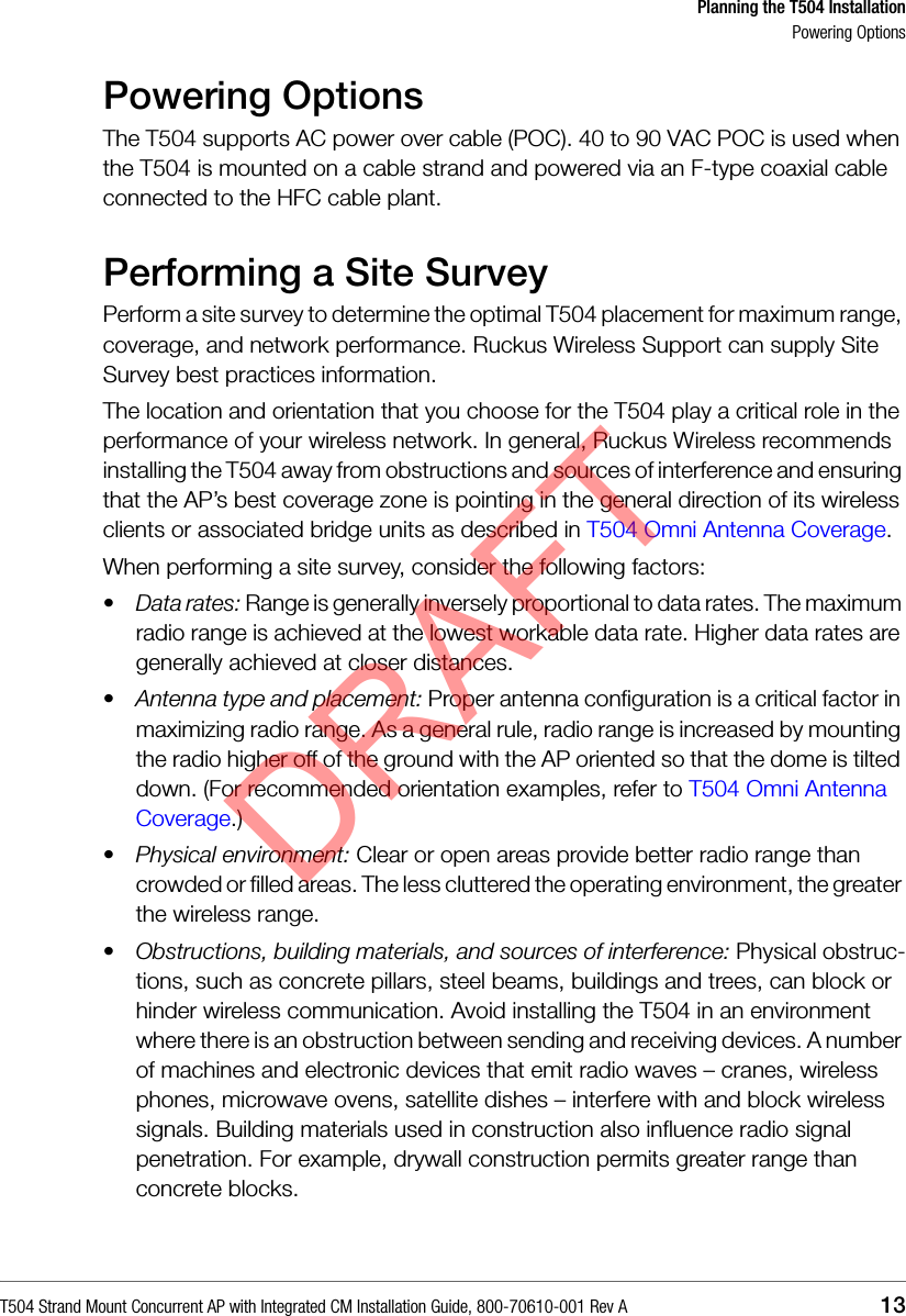
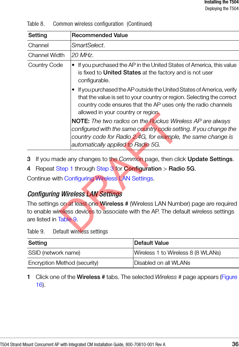
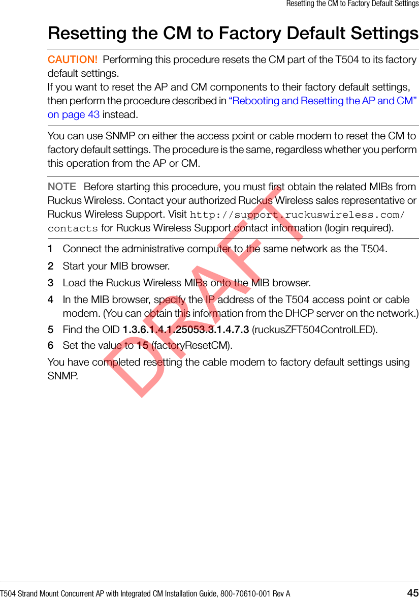
![DimensionsT504 Strand Mount Concurrent AP with Integrated CM Installation Guide, 800-70610-001 Rev A 47Figure 19. T504 height and width--all dimensions in millimeters and [inches]DRAFT](https://usermanual.wiki/Ruckus-Wireless/T504.Users-Manual/User-Guide-2539027-Page-46.png)