Ruckus Wireless T504 IEEE 802.11ac Access Point User Manual
Ruckus Wireless, Inc. IEEE 802.11ac Access Point Users Manual
Contents
- 1. Users Manual
- 2. Regulatory Flyer
Users Manual

T504 Strand Mount Concurrent AP with
Integrated Cable Modem
Installation Guide
Part Number 800-70610-001 Rev A
Draft Published December 2, 2014
www.ruckuswireless.com
DRAFT

T504 Strand Mount Concurrent AP with Integrated CM Installation Guide, 800-70610-001 Rev A ii
Copyright Notice and Proprietary Information
Copyright 2014. Ruckus Wireless, Inc. All rights reserved.
No part of this documentation may be used, reproduced, transmitted, or translated, in any form or by any means,
electronic, mechanical, manual, optical, or otherwise, without prior written permission of Ruckus Wireless, Inc.
(“Ruckus”), or as expressly provided by under license from Ruckus.
Destination Control Statement
Technical data contained in this publication may be subject to the export control laws of the United States of America.
Disclosure to nationals of other countries contrary to United States law is prohibited. It is the reader’s responsibility to
determine the applicable regulations and to comply with them.
Disclaimer
THIS DOCUMENTATION AND ALL INFORMATION CONTAINED HEREIN (“MATERIAL”) IS PROVIDED FOR GENERAL
INFORMATION PURPOSES ONLY. RUCKUS AND ITS LICENSORS MAKE NO WARRANTY OF ANY KIND, EXPRESS
OR IMPLIED, WITH REGARD TO THE MATERIAL, INCLUDING, BUT NOT LIMITED TO, THE IMPLIED WARRANTIES
OF MERCHANTABILITY, NON-INFRINGEMENT AND FITNESS FOR A PARTICULAR PURPOSE, OR THAT THE
MATERIAL IS ERROR-FREE, ACCURATE OR RELIABLE. RUCKUS RESERVES THE RIGHT TO MAKE CHANGES OR
UPDATES TO THE MATERIAL AT ANY TIME.
Limitation of Liability
IN NO EVENT SHALL RUCKUS BE LIABLE FOR ANY DIRECT, INDIRECT, INCIDENTAL, SPECIAL OR CONSEQUEN-
TIAL DAMAGES, OR DAMAGES FOR LOSS OF PROFITS, REVENUE, DATA OR USE, INCURRED BY YOU OR ANY
THIRD PARTY, WHETHER IN AN ACTION IN CONTRACT OR TORT, ARISING FROM YOUR ACCESS TO, OR USE
OF, THE MATERIAL.
Trademarks
Ruckus Wireless, Ruckus, Bark Logo, Simply Better Wireless are trademarks of Ruckus Wireless, Inc. in the United
States and other countries. All other product or company names may be trademarks of their respective owners.
DRAFT

T504 Strand Mount Concurrent AP with Integrated CM Installation Guide, 800-70610-001 Rev A 3
Contents
1 About This Installation Guide
Using this Installation Guide . . . . . . . . . . . . . . . . . . . . . . . . . . . . . . . . . . . . . . . . . . . . . . . 7
Terms Used in This Guide. . . . . . . . . . . . . . . . . . . . . . . . . . . . . . . . . . . . . . . . . . . . . . . . . 9
Related Documentation . . . . . . . . . . . . . . . . . . . . . . . . . . . . . . . . . . . . . . . . . . . . . . . . . . 9
Documentation Feedback. . . . . . . . . . . . . . . . . . . . . . . . . . . . . . . . . . . . . . . . . . . . . . . . 10
2 Planning the T504 Installation
T504 Omni Antenna Coverage . . . . . . . . . . . . . . . . . . . . . . . . . . . . . . . . . . . . . . . . . . . . 12
Powering Options . . . . . . . . . . . . . . . . . . . . . . . . . . . . . . . . . . . . . . . . . . . . . . . . . . . . . . 13
Performing a Site Survey. . . . . . . . . . . . . . . . . . . . . . . . . . . . . . . . . . . . . . . . . . . . . . . . . 13
3 Installing the T504
Safety Information . . . . . . . . . . . . . . . . . . . . . . . . . . . . . . . . . . . . . . . . . . . . . . . . . . . . . . 16
Unpacking the T504 . . . . . . . . . . . . . . . . . . . . . . . . . . . . . . . . . . . . . . . . . . . . . . . . . . . . 17
Package Contents . . . . . . . . . . . . . . . . . . . . . . . . . . . . . . . . . . . . . . . . . . . . . . . . . . . . 17
Finding the AP and CM MAC Addresses. . . . . . . . . . . . . . . . . . . . . . . . . . . . . . . . . . . . . 17
Connectors and Ground Point . . . . . . . . . . . . . . . . . . . . . . . . . . . . . . . . . . . . . . . . . . . . 18
LEDs and Reset Button/Diagnostic Ethernet Port . . . . . . . . . . . . . . . . . . . . . . . . . . . . . . 19
Dimensions. . . . . . . . . . . . . . . . . . . . . . . . . . . . . . . . . . . . . . . . . . . . . . . . . . . . . . . . . . . 20
Deploying the T504. . . . . . . . . . . . . . . . . . . . . . . . . . . . . . . . . . . . . . . . . . . . . . . . . . . . . 21
Mounting the T504. . . . . . . . . . . . . . . . . . . . . . . . . . . . . . . . . . . . . . . . . . . . . . . . . . . . 21
Earth Grounding the T504 . . . . . . . . . . . . . . . . . . . . . . . . . . . . . . . . . . . . . . . . . . . . . . 21
Installing the Cable Power Tap . . . . . . . . . . . . . . . . . . . . . . . . . . . . . . . . . . . . . . . . . . . 22
Powering the T504 with POC. . . . . . . . . . . . . . . . . . . . . . . . . . . . . . . . . . . . . . . . . . . . 22
Checking the Signal Level with an RF Power Meter (Optional) . . . . . . . . . . . . . . . . . . . 24
Configuring the T504 for the First Time (Optional). . . . . . . . . . . . . . . . . . . . . . . . . . . . . 25
Preparing the Administrative Computer . . . . . . . . . . . . . . . . . . . . . . . . . . . . . . . . . . . 25
Operating the CM . . . . . . . . . . . . . . . . . . . . . . . . . . . . . . . . . . . . . . . . . . . . . . . . . . . 27
Configuring the AP for Standalone Operation . . . . . . . . . . . . . . . . . . . . . . . . . . . . . . 34
Verifying CM and AP Operation. . . . . . . . . . . . . . . . . . . . . . . . . . . . . . . . . . . . . . . . . . . . 37
4 Operating and Troubleshooting the T504
Retrieving the CM’s MAC Address . . . . . . . . . . . . . . . . . . . . . . . . . . . . . . . . . . . . . . . . . 38
Retrieving the CM’s MAC Address. . . . . . . . . . . . . . . . . . . . . . . . . . . . . . . . . . . . . . . . 38
DRAFT

T504 Strand Mount Concurrent AP with Integrated CM Installation Guide, 800-70610-001 Rev A 4
Retrieving the CM’s MAC Address using the CM CLI . . . . . . . . . . . . . . . . . . . . . . . . 38
Retrieving the CM’s MAC Address using the AP CLI . . . . . . . . . . . . . . . . . . . . . . . . . 39
Rebooting and Resetting the T504 . . . . . . . . . . . . . . . . . . . . . . . . . . . . . . . . . . . . . . . . . 39
How Radio Frequency Scanning Works . . . . . . . . . . . . . . . . . . . . . . . . . . . . . . . . . . . . . 40
5 What to Do Next
Changing the Administrative Password . . . . . . . . . . . . . . . . . . . . . . . . . . . . . . . . . . . . . . 41
Configuring the Security Settings . . . . . . . . . . . . . . . . . . . . . . . . . . . . . . . . . . . . . . . . . . 41
Configuring Advanced Settings and Features . . . . . . . . . . . . . . . . . . . . . . . . . . . . . . . . . 41
Reading Related Documentation. . . . . . . . . . . . . . . . . . . . . . . . . . . . . . . . . . . . . . . . . . . 41
Appendix A: Ruckus Wireless Factory- and Customer-Supplied Parts
Appendix B: Rebooting and Resetting the T504
Rebooting and Resetting the AP and CM . . . . . . . . . . . . . . . . . . . . . . . . . . . . . . . . . . . . 43
Using the Reset Button Inside the AP. . . . . . . . . . . . . . . . . . . . . . . . . . . . . . . . . . . . . . 43
Remotely Rebooting the AP . . . . . . . . . . . . . . . . . . . . . . . . . . . . . . . . . . . . . . . . . . . . . 44
Resetting the CM to Factory Default Settings . . . . . . . . . . . . . . . . . . . . . . . . . . . . . . . . . 45
Appendix C: T504 Mounting Dimensions and Weight
Dimensions. . . . . . . . . . . . . . . . . . . . . . . . . . . . . . . . . . . . . . . . . . . . . . . . . . . . . . . . . . . 46
Weight . . . . . . . . . . . . . . . . . . . . . . . . . . . . . . . . . . . . . . . . . . . . . . . . . . . . . . . . . . . . . . 48
DRAFT
T504 Strand Mount Concurrent AP with Integrated CM Installation Guide, 800-70610-001 Rev A 6
1
About This Installation Guide
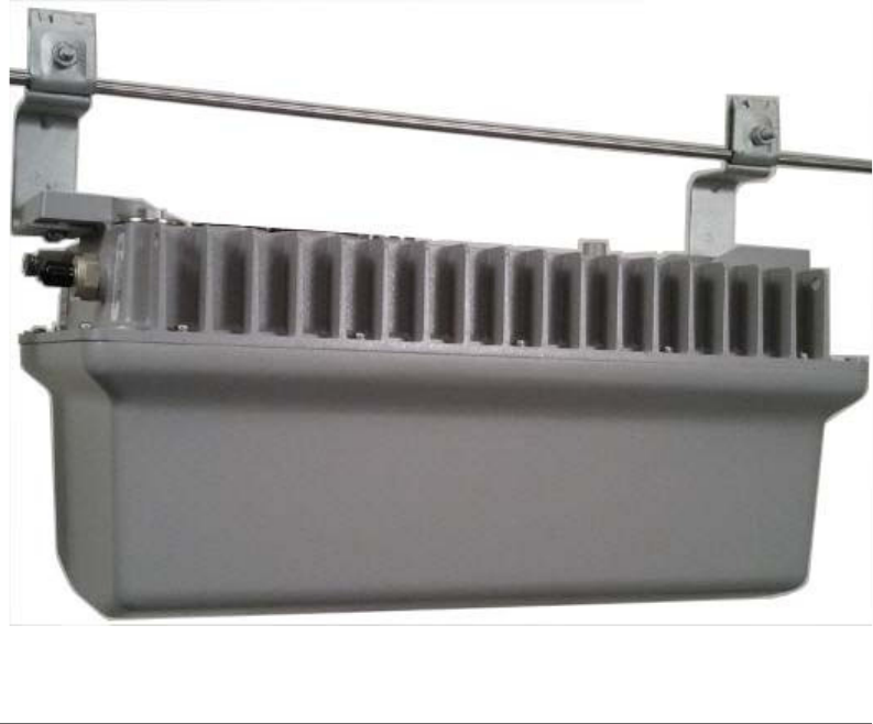
This Installation Guide provides information on how to set up the Ruckus Wireless
Strand Mount Concurrent Access Point with Integrated Cable Modem (T504) on
your network. Topics covered in this guide include basic configuration, operation
and mounting. The rest of this document refers to the Strand Mount Concurrent
Access Point with Integrated Cable Modem as the T504.
This guide is intended for use by those installing and configuring network equipment.
Consequently, it assumes a basic working knowledge of local area networking, cable
modem setup and configuration, wireless networking, and wireless devices.
Figure 1. Typical T504 mounted on a strand
DRAFT
About This Installation Guide
Using this Installation Guide
T504 Strand Mount Concurrent AP with Integrated CM Installation Guide, 800-70610-001 Rev A 7
Using this Installation Guide
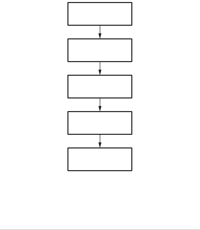
The T504 installation is completed with five main steps. Each step includes some
substeps. Figure 2 shows the main steps, and Ta b le 1 includes the substeps.
Figure 2. Adding a T504 to an existing Ruckus Wireless network flowchart
Planning
the Installation
Preparing at the Depot
and Sending to the Field
Installing
in the Field
Operating and
Troubleshooting
What to Do
Next
DRAFT

About This Installation Guide
Using this Installation Guide
T504 Strand Mount Concurrent AP with Integrated CM Installation Guide, 800-70610-001 Rev A 8
NOTE The AP part of the T504 can be managed using an AP web browser
interface, an AP command line interface (CLI), and a simple network management
protocol (SNMP) interface.
Table 1. Adding a T504 to an Existing Ruckus Wireless network
Section Heading
2Planning the T504 Installation
• T504 Omni Antenna Coverage
• Powering Options
• Performing a Site Survey
3Installing the T504
• Safety Information
• Unpacking the T504
• Finding the AP and CM MAC Addresses
• Connectors and Ground Point
• LEDs and Reset Button/Diagnostic Ethernet Port
• Dimensions
• Deploying the T504
• Verifying CM and AP Operation
4Operating and Troubleshooting the T504
• Retrieving the CM’s MAC Address
• Rebooting and Resetting the T504
• How Radio Frequency Scanning Works
5What to Do Next
• Changing the Administrative Password
• Configuring the Security Settings
• Configuring Advanced Settings and Features
• Reading Related Documentation
DRAFT

About This Installation Guide
Terms Used in This Guide
T504 Strand Mount Concurrent AP with Integrated CM Installation Guide, 800-70610-001 Rev A 9
Terms Used in This Guide
Before continuing, Ruckus Wireless recommends that you become familiar with the
following terms:
•T504: T504 Cable Modem Access Point, which includes the CM and AP and
the cable strand interface.
•AP: The Wi-Fi Access Point part of the T504 Cable Modem Access Point.
•CM: The Cable Modem part of the T504 Cable Modem Access Point.
•CMTS: Cable modem termination system high speed data services equipment.
•HFC: Hybrid fiber coax broadband network.
•MSO: Multiple system operator.
Related Documentation
In addition to this guide, each Cable Modem Access Point documentation set
includes the following:
•User Guide: Provides detailed information on how to configure the functions of
the unit. The User Guide is available for download on the Ruckus Wireless
Support Web site at
http://support.ruckuswireless.com/documents
•Release Notes: Provides late-breaking information about the current software
release, including new features, enhancements, and known issues. If the infor-
mation in the Release Notes differs from the information in this guide, follow the
instructions in the Release Notes.
•Online Help: Accessible from the T504’s Web interface, the Online Help provides
information that helps you configure the device from the Web interface.
DRAFT

About This Installation Guide
Documentation Feedback
T504 Strand Mount Concurrent AP with Integrated CM Installation Guide, 800-70610-001 Rev A 10
Documentation Feedback
Ruckus Wireless is interested in improving its documentation and welcomes your
comments and suggestions. You can email your comments to Ruckus Wireless at
docs@ruckuswireless.com
When contacting us, please include the following information:
• Document title
• Document part number (on the cover page)
• Page number (if appropriate)
For example:
• T504 Strand Mount Concurrent AP with Integrated CM Installation Guide
• Part number: 800-70610-001 Rev A
• Page 11
DRAFT

Planning the T504 Installation
T504 Omni Antenna Coverage
T504 Strand Mount Concurrent AP with Integrated CM Installation Guide, 800-70610-001 Rev A 12
T504 Omni Antenna Coverage
The T504 (ordering part number 975-T504-US31) includes internal 5GHz and
2.4GHz omnidirectional antennas, and is equipped with a DOCSIS 3.0 cable
modem.
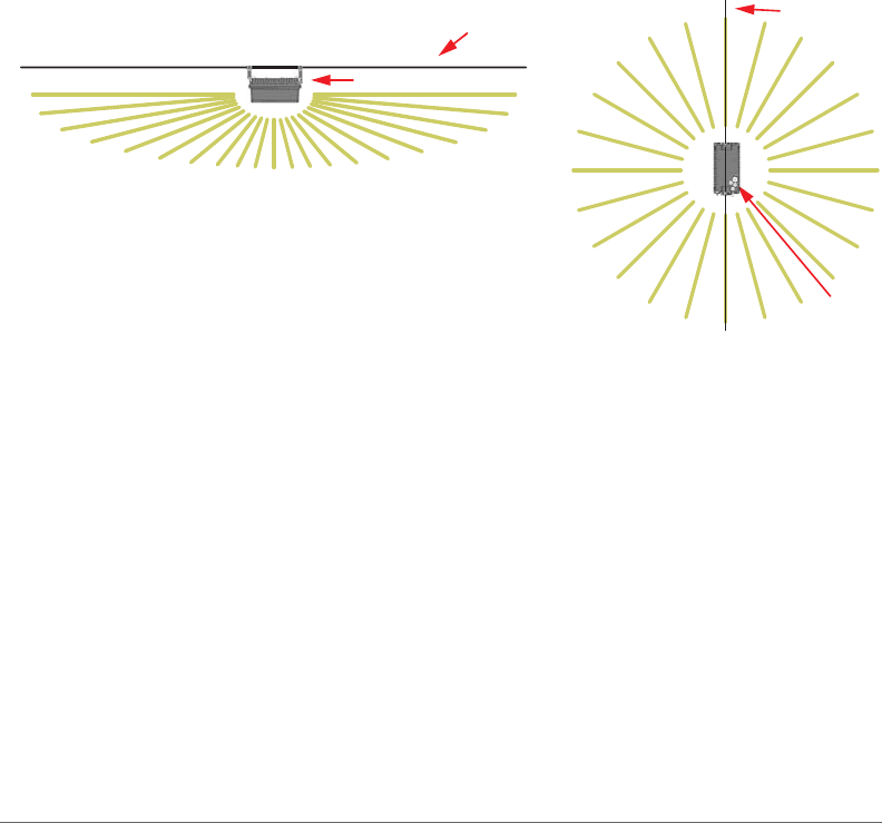
The T504s are best deployed where internal-antenna lateral beamforming can
provide the greatest reach and throughput to a wide coverage area, and provide
the greatest distance between APs in a connecting device. See Figure 3 for internal-
antenna coverage patterns.
Figure 3. Omni 5GHz and 2.4GHz coverage
Good Reach
Excellent
Reach
Excellent
Reach
Elevation Plane Coverage
Cable
Strand
T504
Azimuth Plane Coverage
Cable Strand
T504
DRAFT

Planning the T504 Installation
Powering Options
T504 Strand Mount Concurrent AP with Integrated CM Installation Guide, 800-70610-001 Rev A 13
Powering Options
The T504 supports AC power over cable (POC). 40 to 90 VAC POC is used when
the T504 is mounted on a cable strand and powered via an F-type coaxial cable
connected to the HFC cable plant.
Performing a Site Survey
Perform a site survey to determine the optimal T504 placement for maximum range,
coverage, and network performance. Ruckus Wireless Support can supply Site
Survey best practices information.
The location and orientation that you choose for the T504 play a critical role in the
performance of your wireless network. In general, Ruckus Wireless recommends
installing the T504 away from obstructions and sources of interference and ensuring
that the AP’s best coverage zone is pointing in the general direction of its wireless
clients or associated bridge units as described in T504 Omni Antenna Coverage.
When performing a site survey, consider the following factors:
•Data rates: Range is generally inversely proportional to data rates. The maximum
radio range is achieved at the lowest workable data rate. Higher data rates are
generally achieved at closer distances.
•Antenna type and placement: Proper antenna configuration is a critical factor in
maximizing radio range. As a general rule, radio range is increased by mounting
the radio higher off of the ground with the AP oriented so that the dome is tilted
down. (For recommended orientation examples, refer to T504 Omni Antenna
Coverage.)
•Physical environment: Clear or open areas provide better radio range than
crowded or filled areas. The less cluttered the operating environment, the greater
the wireless range.
•Obstructions, building materials, and sources of interference: Physical obstruc-
tions, such as concrete pillars, steel beams, buildings and trees, can block or
hinder wireless communication. Avoid installing the T504 in an environment
where there is an obstruction between sending and receiving devices. A number
of machines and electronic devices that emit radio waves – cranes, wireless
phones, microwave ovens, satellite dishes – interfere with and block wireless
signals. Building materials used in construction also influence radio signal
penetration. For example, drywall construction permits greater range than
concrete blocks.
DRAFT

Planning the T504 Installation
Performing a Site Survey
T504 Strand Mount Concurrent AP with Integrated CM Installation Guide, 800-70610-001 Rev A 14
•Mounting: The T504 is designed to clamp onto a 1/4” to 3/8” (6.35mm to 10mm)
support wire. The hangers allow a 2” bundle of cables between the support wire
and the T504.
•Power and backhaul connections: The T504 needs a backhaul connection to
the CMTS and it needs to be close enough to an AC power inserter on the CATV
cable to assure that it is able to pull 20 watts at greater than 40 VAC. If not, then
another power inserter must be installed closer to the T504.
When you are done planning the T504 installation, continue with Installing the T504.
DRAFT

T504 Strand Mount Concurrent AP with Integrated CM Installation Guide, 800-70610-001 Rev A 15
3
Installing the T504
Before installing the T504, Ruckus Wireless recommends that you first complete
the procedures described in Planning the T504 Installation.
In this chapter:
•Safety Information
•Unpacking the T504
•Finding the AP and CM MAC Addresses
•Connectors and Ground Point
•LEDs and Reset Button/Diagnostic Ethernet Port
•Dimensions
•Deploying the T504
•Verifying CM and AP Operation
DRAFT

Installing the T504
Safety Information
T504 Strand Mount Concurrent AP with Integrated CM Installation Guide, 800-70610-001 Rev A 16
Safety Information
WARNING! Only trained and qualified installers should be allowed to install,
replace, or service this equipment.
The professional installer is responsible for the proper installation and configuration
of this AP. The AP installation must comply with local regulatory requirements,
especially with those regulating operation near military and/or weather radar
systems.
WARNING! Installation of this equipment must comply with local and national
electrical codes.
WARNING! Ruckus Wireless strongly recommends that you wear eye protection
before mounting the AP.
CAUTION! Make sure that you form a 80mm - 130mm (3”-5”) drip loop in any cable
that is attached to the AP or other equipment. This will prevent water from running
along the cable and entering the AP or other equipment.
CAUTION! Be sure that grounding is available and that it meets local and national
electrical codes. For additional lightning protection, use lightning rods and lightning
arrestors.
CAUTION! Make sure that proper lightning surge protection precautions are taken
according to local electrical code.
DRAFT

Installing the T504
Unpacking the T504
T504 Strand Mount Concurrent AP with Integrated CM Installation Guide, 800-70610-001 Rev A 17
Unpacking the T504
1Open the T504 package, and then carefully remove the contents.
2Return all packing materials to the shipping box, and put the box away in a dry
location.
3Verify that all items listed in Package Contents are included in the package.
Check each item for damage. If any item is damaged or missing, notify your
authorized Ruckus Wireless sales representative.
NOTE Appendix A: Ruckus Wireless Factory- and Customer-Supplied Parts
includes illustrations and descriptions of these and other factory-orderable and
customer-supplied parts.
Package Contents
A Ruckus Wireless T504 package contains the items listed below:
• Ruckus Wireless T504 unit with cable strand hangers, includes one 12mm
stainless steel M6x1 earth ground panhead screw with split lock and flat washers
• One green/yellow earth ground wire with ring terminal
• Service Level Agreement/Limited Warranty Statement
• Regulatory Statement
• Declaration of Conformity, if required
•This Installation Guide
Finding the AP and CM MAC Addresses
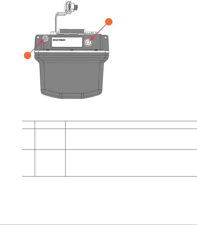
The T504 has separate MAC addresses for the internal AP and cable modem (CM),
mounted on the end of the T504 with the F-type connector and the ground screw
(see Figure 4).
Continue with Connectors and Ground Point.
DRAFT
Installing the T504
Connectors and Ground Point
T504 Strand Mount Concurrent AP with Integrated CM Installation Guide, 800-70610-001 Rev A 18
Connectors and Ground Point
Figure 4 identifies the connector and external ground point on the T504. Ta ble 2
describes this connector and the ground point.
Figure 4. T504 connectors and ground point
Table 2. Connectors and ground point on the T504
No. Label Description
1 Coaxial Cable
Connector
Connects to the CMTS at the headend using a tap on the plant,
and provides AC POC to the T504. For more information, refer to
Powering Options.
2 Optional
External Earth
Ground Point
The T504 is normally earth-grounded by the cable strand.
However, if the cable strand is not earth grounded, then connect
an external earth ground to the T504 using this screw-and-washer
set.
1
2
DRAFT
Installing the T504
LEDs and Reset Button/Diagnostic Ethernet Port
T504 Strand Mount Concurrent AP with Integrated CM Installation Guide, 800-70610-001 Rev A 19
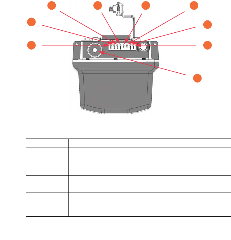
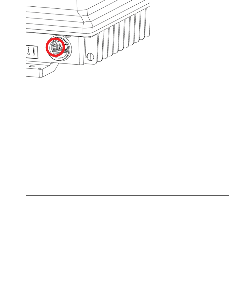
LEDs and Reset Button/Diagnostic Ethernet
Port
Use the eight LEDs to check the status of the access point and cable modem. Figure
5 shows the LEDs on the T504, and Ta b l e 3 describes the LEDs and the reset
button/diagnostic Ethernet port.
Figure 5. T504 LEDs and reset button/diagnostic Ethernet port when the dome is pointing
downwards
Table 3. LEDs and reset button/diagnostic Ethernet port
No. Label Description
1POWER•
Dark: Off.
•Red: Boot up in process.
•Green: On.
2 CM DS • Blinks when searching for downstream (DS), then solid when DS
is locked. Also blinks during CM boot when power is applied.
3 CM US • Off when DS is searching, and then blinks as upstream power is
increased/ranged and then solid when upstream ranging is
complete. Also blinks during CM boot when power is applied.
6
7
8
5
1
3
2
4
9
DRAFT

Installing the T504
Dimensions
T504 Strand Mount Concurrent AP with Integrated CM Installation Guide, 800-70610-001 Rev A 20
Dimensions
“Appendix C: T504 Mounting Dimensions and Weight” on page 46 contains the
dimensions for the T504.
4 ONLINE • Off until CM DS and CM US are solid ON, then blinks as the CM
obtains an IP address and a configuration file, and then comes
online and LED is solid. Also blinks during CM boot when power
is applied.
5DIR •
Always Off: The Access Point is not being managed by a Ruckus
Wireless controller.
6AIR •
Off: The Access Point is operating in standalone mode.
•Green: The wireless signal to its uplink AP is good.
7 2.4 GHz • Off: The WLAN service is down.
•Green: The WLAN is up and at least one client is associated.
•Amber: The WLAN is up. No clients are associated.
85 GHz•
Off: The WLAN service is down.
•Amber: The WLAN is up, but no clients are associated/connected.
•Green: The WLAN is up and at least one client is associated.
9 -- Reset button and diagnostic Ethernet port -- Use a 7/16” (11mm)
wrench to remove the screw-in plug.
• After removing the plug, press the reset button for ten seconds to
reset the AP part of the T504 to factory default.
CAUTION: DO NOT DO THIS UNLESS SO INSTRUCTED.
Doing this resets the AP IP address to 192.168.100.2.
• After removing the plug, you can see the diagnostic Ethernet port.
This port is used for diagnostics and/or initial configuration.
Table 3. LEDs and reset button/diagnostic Ethernet port (Continued)
No. Label Description
DRAFT

Installing the T504
Deploying the T504
T504 Strand Mount Concurrent AP with Integrated CM Installation Guide, 800-70610-001 Rev A 21
Deploying the T504
In this section, you will mount the T504 in its final mounting location. Perform the
following:
•Mounting the T504
•Earth Grounding the T504
•Installing the Cable Power Tap
•Powering the T504 with POC
•Checking the Signal Level with an RF Power Meter (Optional)
•Configuring the T504 for the First Time (Optional)
Mounting the T504
To mount the T504 assembly on a cable strand, you need to secure the cable
clamps that are attached to the strand interface to the cable strand.
1Slightly loosen the nuts that fasten the two cable clamps to the strand interface,
enough for the strand support cable to fit into the cable clamps.
2Place the cable clamps on the strand support cable.
3Tighten the two cable clamp nuts to 22 to 27 N.m (16 to 20 ft-lbs) to secure the
mounting.
You have mounted the T504. Continue with Earth Grounding the T504.
Earth Grounding the T504
The cable strand is usually earth-grounded, and mounting the T504 on the cable
strand earth grounds the T504 chassis as well; if this is the case, skip this procedure
and continue with Installing the Cable Power Tap.
CAUTION! Be sure that earth grounding is available and that it meets local and
national electrical codes. For additional lightning protection, use lightning rods and
lightning arrestors.
.
If the cable strand is not earth-grounded, then continue with the following:
1The color coding of ground wires varies by region. Before completing this step,
check your local wiring standards for guidance.
2Using the factory-supplied ground screw and washers, use the factory-supplied
earth ground wire with ring terminal to connect a good earth ground to the T504
using the chassis ground screw shown in Figure 4.
DRAFT
Installing the T504
Deploying the T504
T504 Strand Mount Concurrent AP with Integrated CM Installation Guide, 800-70610-001 Rev A 22
CAUTION! The T504 includes one 12mm stainless steel M6x1 earth ground screw
with split lock and flat washers. Make sure that any replacement screw is no longer
than 12mm. If a screw is longer than 12mm, it can damage the T504 chassis.
.
You have earth-grounded the T504. Continue with Installing the Cable Power Tap.
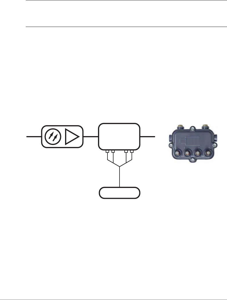
Installing the Cable Power Tap
The CATV coaxial cable used in the field deployment must have 40 to 90 VAC power
multiplexed with the RF signal on the coaxial cable, since the T504 Connector B is
used for both electrical power and the RF signal.
Ruckus Wireless recommends installing a cable power tap (Antronix MGT2000-
SDPE tap, or equivalent) close to the T504. Refer to the manufacturer’s instructions
to mount the cable power tap on the coaxial cable. Figure 6 shows a typical cable
power tap and connection to the CM using an RG6 quad shield cable.
Figure 6. Cable Power Tap Connection to the T504 Cable Modem
Continue with Powering the T504 with POC.
Powering the T504 with POC
40 to 90 VAC POC is used when the T504 is mounted on a cable strand and
powered via an F-type coaxial cable connected to the HFC cable plant.
1Remove the power jumper from the power tap to remove AC power out of the
power tap.
High Output Node
Tap
Cable Modem
Typical Cable Power Tap
Typical Cable Power Tap Connection
DRAFT

Installing the T504
Deploying the T504
T504 Strand Mount Concurrent AP with Integrated CM Installation Guide, 800-70610-001 Rev A 23
2Insert the F-type coaxial cable that is connected to the HFC cable plant to the
F-type connector on the T504. Power is supplied through a power passing tap
on the CATV coax. The tap is connected to F-type connector on the T504 as
shown in Figure 4.
3Finger tighten the coaxial cable connector and then tighten to 3.4 N.m (30 in-lbs).
4Plug the power jumper back into the power tap to restore AC power out of the
power tap.
5When the T504 receives power, its LEDs flash on and off as it goes through a
power-on self test and then receives its AP and CM configurations from the cable
operator.
NOTE Normally, the T504 receives its AP and CM configurations from the cable
operator. This means that the installer does not need to manually configure either
the AP or the CM part of the T504.
6Wait until the T504 PWR, CM DS, CM US, and ONLINE LEDs stop flashing and
then remain on.
You have verified that the T504 is powered. Continue with Checking the Signal Level
with an RF Power Meter (Optional).
DRAFT

Installing the T504
Deploying the T504
T504 Strand Mount Concurrent AP with Integrated CM Installation Guide, 800-70610-001 Rev A 24
Checking the Signal Level with an RF Power Meter
(Optional)
The CMAP cable modem is just like the standard DOCSIS 3.0 modem installed at
home.
Connect an RF power meter to the cable from the cable power tap.
Select a CATV power passing tap that supplies a signal level between -12 and
+16dBmV at its output (prefer 0 to 6dBmV).
Tab l e 4 lists the signal level specifications to coaxial cable connector on the CMAP.
Continue with Configuring the T504 for the First Time (Optional).
Table 4. Coaxial cable connector signal level specifications
Downstream Upstream
-12 to +16dBmV/64 QAM
--or--
-12 to +16dBmV/256 QAM
TDMA: (1xUpstream)
• Pmin to +57dBmV (32 QAM, 64 QAM)
• Pmin to +58dBmV (8 QAM, 16 QAM)
• Pmin to +58dBmV (QPSK)
S-CDMA: (1xUpstream)
• Pmin to +56dBmV (all modulations), where:
• Pmin = +17dBmV, 1280kHz modulation rate
• Pmin = +20dBmV, 2560kHz modulation rate
• Pmin = +23dBmV, 5120kHz modulation rate
TDMA: (4xUpstream)
• Pmin to +51dBmV (32 QAM, 64 QAM)
• Pmin to +52dBmV (8 QAM, 16 QAM)
• Pmin to +55dBmV (QPSK)
S-CDMA: (4xUpstream)
• Pmin to +53dBmV (all modulations), where:
• Pmin = +17dBmV, 1280kHz modulation rate
• Pmin = +20dBmV, 2560kHz modulation rate
• Pmin = +23dBmV, 5120kHz modulation rate
DRAFT

Installing the T504
Deploying the T504
T504 Strand Mount Concurrent AP with Integrated CM Installation Guide, 800-70610-001 Rev A 25
Configuring the T504 for the First Time (Optional)
NOTE The T504 normally receives its latest AP and CM firmware downloads and
initial configurations from the cable modem termination system high speed data
services (CMTS) equipment when it powers up; if this is the case, then skip this
section and continue with Verifying CM and AP Operation.
If the T504 AP and CM do not receive their latest firmware downloads and initial
configurations from the CMTS equipment when the T504 powers up, then continue
with this procedure:
•Preparing the Administrative Computer
•Operating the CM
•Configuring the AP for Standalone Operation
Preparing the Administrative Computer
Use an administrative computer to configure basic operational parameters for the
T504 access point and cable modem parts.
NOTE The following procedure is applicable if the administrative computer is
running Windows 7 or Windows XP. If you are using a different operating system,
refer to the documentation that was shipped with your operating system for
information on how to modify the computer’s IP address settings.
1Collect required equipment and information:
• An administrative computer (notebook computer) running Windows 7/Vista/
XP/2000 with one wireless 802.11b/g/n network card and one Ethernet card
installed.
• Mozilla Firefox 2.0 (or later) or Microsoft Internet Explorer 6.0 (or later) installed
on the administrative computer.
• A Telnet or SSH (secure shell) client program installed on the administrative
computer.
2On your Windows computer, open the Network Connections (or Network and
Dial-up Connections) control panel according to how the Start menu is set up:
•On Windows 7, click Start > Control Panel > Network and Sharing Center
> Change Adapter Settings.
• On Windows XP, click Start > Control Panel > Network Connections.
3When the Network Connections window appears, right-click the icon for Local
Area Connection, and then click Properties.
DRAFT
Installing the T504
Deploying the T504
T504 Strand Mount Concurrent AP with Integrated CM Installation Guide, 800-70610-001 Rev A 26
NOTE Make sure that you configure the Local Area Connection properties, not the
Wireless Network Connection properties.
4When the Local Area Connection Properties dialog box appears, select Internet
Protocol (TCP/IP) or TCP/IPv4 in Windows 7 from the scrolling list, and then
click Properties. The Internet Protocol (TCP/IP) Properties dialog box appears.
5Write down all of the currently active network settings. You will need this
information later when you restore your computer to its current network
configuration.
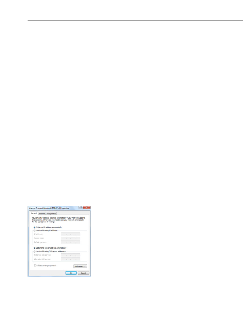
6Click Obtain an IP address automatically, and then configure the IP address
settings with the values listed in Ta ble 5 . For a sample configuration, refer to
Figure 7.
Figure 7. Sample configuration in the Internet Protocol Version 4 (TCP/IPv4) Properties dialog
box
7Click OK to save your changes and close the TCP/IP Properties dialog box.
8Click OK again to close the Local Area Connection Properties dialog box.
Table 5. Configure your computer’s IP address settings
IP address Obtain an IP address automatically.(Avoid 192.168.100.1,
which is the default IP address assigned to the CM, and 192.168.100.2,
which is the default IP address assigned to the AP.)
Subnet mask 255.255.255.0
Note 1: The administrative computer needs to be able to connect with 192.168.100.2,
the IP address for the AP. The administrative computer also needs to connect with the
CM, which has probably been assigned a new IP address by the network DHCP server.
Note 2: You can leave the Default Gateway and DNS server fields blank.
DRAFT

Installing the T504
Deploying the T504
T504 Strand Mount Concurrent AP with Integrated CM Installation Guide, 800-70610-001 Rev A 27
Windows saves the IP address settings that you have configured.
Operating the CM
In addition to the T504 AP command line interface (CLI) and web interface, the CM
part of the T504 also has web and CLI interfaces. With these interfaces, you can
operate the CM part. Refer to the following sections:
NOTE The cable modem and access point each has its own independent firmware
load that is updated independently.
•About the CM Command Line and Web Interfaces
•Logging Into the CM Web Interface from the T504 Ethernet Port
•Logging Into the CM Web Interface using a Dynamic IP Address
•Viewing the Software Status
•Viewing the Connection Status
•Configuring the Downstream Frequency
•Administering Cable Modem Passwords
•Viewing the SNMP Event Log
About the CM Command Line and Web Interfaces
The CM command line interface is similar to the AP CLI, and is used for CM-specific
operations. You can perform most CM operating tasks from the CM web interface.
Logging Into the CM Web Interface from the T504 Ethernet Port
1Collect required equipment and information:
• The IP address assigned to the CM by the CMTS DHCP server.
• An administrative computer as configured as described in Preparing the
Administrative Computer.
• One Cat5e or better Ethernet cable.
2Use a 7/16” (11mm) wrench to remove the reset button and diagnostic Ethernet
port screw-in plug (see Figure 5).
3Connect one end of an Ethernet cable to the Ethernet port on the T504, and
then connect the other end to the administrative computer’s Ethernet port.
4On the administrative computer, open a web browser window.
DRAFT

Installing the T504
Deploying the T504
T504 Strand Mount Concurrent AP with Integrated CM Installation Guide, 800-70610-001 Rev A 28
5In the address or location bar, type the CM IP address, for instance:
192.168.100.1
--OR--
<DHCP-assigned CM IP address>
The cable modem web interface displays a login prompt.
6Leave User Name blank.
7In Password, type ADMIN.
8Click Log In. The Connection Status page appears, indicating that you have
successfully logged on to the cable modem web interface.
Continue with Viewing the Software Status.
Logging Into the CM Web Interface using a Dynamic IP Address
1Collect required equipment and information:
• An administrative computer as configured as described in Preparing the
Administrative Computer.
• The IP address assigned to the cable modem by the DHCP server at the
CMTS.
2Use a 7/16” (11mm) wrench to remove the reset button and diagnostic Ethernet
port screw-in plug (see Figure 5).
3Connect the administrative computer to the same subnet as the T504.
4On the administrative computer, start a Web browser.
5In the address bar, enter the IP address that is assigned to the cable modem.
The cable modem web interface displays a login prompt.
6Leave User Name blank.
7In Password, type ADMIN.
8Click Log In. The Connection Status page appears, indicating that you have
successfully logged on to the cable modem web interface.
Continue with Viewing the Software Status.
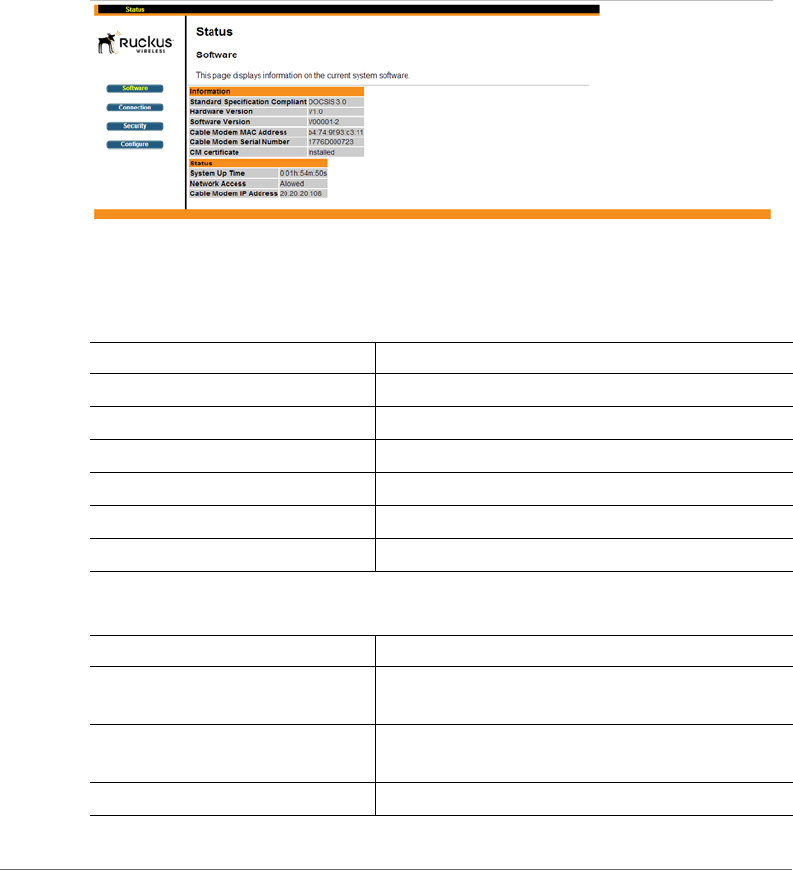
Viewing the Software Status
The Software Status page displays information about the current software version
installed on the cable modem and the CM system status.
DRAFT
Installing the T504
Deploying the T504
T504 Strand Mount Concurrent AP with Integrated CM Installation Guide, 800-70610-001 Rev A 29
1Log into to the Status page as described in Logging Into the CM Web Interface
from the T504 Ethernet Port or Logging Into the CM Web Interface using a
Dynamic IP Address.
2In the left sidebar, click Software. The Software Status page appears, as shown
in Figure 8.
Figure 8. Software Status page
There are two tables on the Software Status page – Information and Status. Table
6 and Tab l e 7 describe the information that these tables display.
Table 6. Information (software) table
Item Description
Standard Specification Compliant The standard with which the device is compliant.
Hardware Version The version of the cable modem hardware.
Software Version The version of the cable modem software.
Cable Modem MAC Address The MAC address of the cable modem.
Cable Modem Serial Number The serial number of the cable modem.
CM Certificate Indicates whether a security certificate is installed.
Table 7. Status table
Item Description
System Up Time Indicates the time that has elapsed since the cable
modem was last rebooted.
Network Access Indicates whether or not the cable modem is
connected to the network.
Cable Modem IP Address The IP address assigned to the CM.
DRAFT
Installing the T504
Deploying the T504
T504 Strand Mount Concurrent AP with Integrated CM Installation Guide, 800-70610-001 Rev A 30
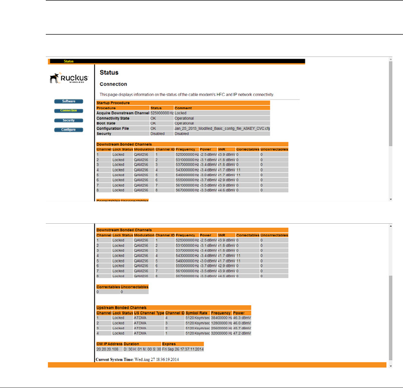
Viewing the Connection Status
The Connection Status page displays information about the cable modem’s Hybrid
Fiber Coax (HFC) and IP network connectivity, including its downstream and
upstream channels and the IP address that is currently assigned to the cable
modem.
1Log into to the Status page as described in Logging Into the CM Web Interface
from the T504 Ethernet Port or Logging Into the CM Web Interface using a
Dynamic IP Address.
2Click Connection in the left sidebar. The CM web interface displays the
Connection Status page.
NOTE The Downstream Power indicated in the Power column is accurate to
+/-3dB.
Figure 9. Connection Status page - Page 1 of 2
Figure 10. Connection Status page - Page 2 of 2
DRAFT
Installing the T504
Deploying the T504
T504 Strand Mount Concurrent AP with Integrated CM Installation Guide, 800-70610-001 Rev A 31
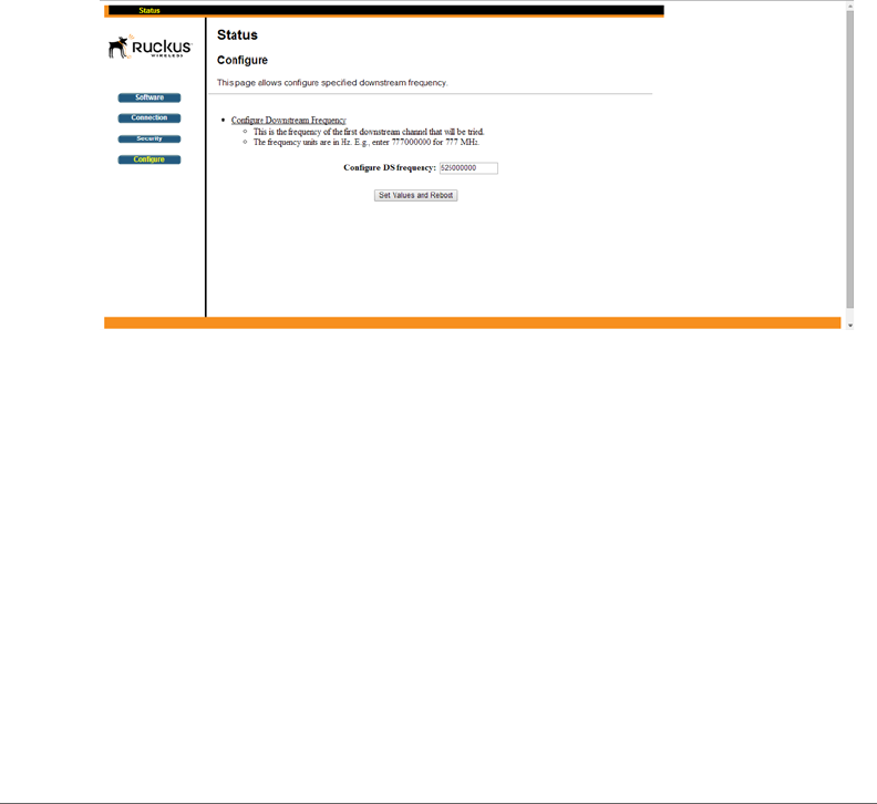
Configuring the Downstream Frequency
The Configure Status page allows you to set the downstream frequency for the
cable modem. Configuring the downstream frequency enables the device to quickly
obtain a direct frequency lock with the CMTS upon bootup and helps to save several
minutes of scanning for an available downstream frequency from the CMTS.
1Log into the Status page as described in Logging Into the CM Web Interface
from the T504 Ethernet Port or Logging Into the CM Web Interface using a
Dynamic IP Address.
2Click Configure in the left sidebar. The CM web interface displays the Configure
Status page. See Figure 11.
Figure 11. Configure Status page
3In the Configure DS Frequency text box, enter the downstream frequency (in
Hertz) that you want the cable modem to use to connect to the CMTS when it
boots up.
4Click Set Values and Reboot to have the cable modem save your changes and
reboot.
DRAFT
Installing the T504
Deploying the T504
T504 Strand Mount Concurrent AP with Integrated CM Installation Guide, 800-70610-001 Rev A 32
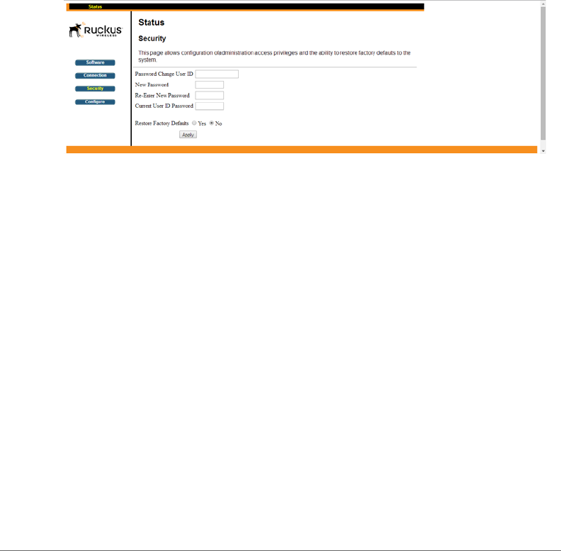
Administering Cable Modem Passwords
The parameters on the Security Status page allow you to change the CM login and
password, and/or restore the factory defaults.
1Log into to the Status page as described in Logging Into the CM Web Interface
from the T504 Ethernet Port or Logging Into the CM Web Interface using a
Dynamic IP Address.
2Click Security in the left sidebar. The CM web interface displays the Security
Status page.
Figure 12. Security Status page
3Ruckus Wireless recommends that you change the login and/or password as
follows:
aEnter a new CM user ID in Password Change User ID.
bEnter a new CM user password in New Password.
cIf you are changing the password, then re-enter the new CM user password
in Re-Enter New Password.
dEnter the existing (before change) CM user password in Current User ID
Password.
4Restore the factory defaults as follows:
• Select the Restore Factory Defaults Yes button to reset all the CM parameters
to the factory default settings after the next reboot.
• Select the Restore Factory Defaults No button to prevent a reset all CM
parameters to the factory defaults after the next reboot.
5If you have made any changes on the Security Status page, then click Apply.
• If you have selected the Restore Factory Defaults Yes, then the CM reboots
and resets all CM parameters to the factory defaults.
DRAFT

Installing the T504
Deploying the T504
T504 Strand Mount Concurrent AP with Integrated CM Installation Guide, 800-70610-001 Rev A 33
• If you have selected the Restore Factory Defaults No, then the CM web
interface saves your changes and returns you to the Security Status page.
Viewing the SNMP Event Log
1Log into to the Status page as described in Logging Into the CM Web Interface
from the T504 Ethernet Port or Logging Into the CM Web Interface using a
Dynamic IP Address.
2Click Event Log on the menu on the left sidebar. The CM web interface displays
the SNMP Event Log Status page.
3View the SNMP events in the SNMP event log.
Figure 13. SNMP Event Log Status page
4If you would like to delete the SNMP events in the SNMP event log, then click
Clear Log at the bottom of the page.
Continue with Configuring the AP for Standalone Operation.
(To be determined)
DRAFT

Installing the T504
Deploying the T504
T504 Strand Mount Concurrent AP with Integrated CM Installation Guide, 800-70610-001 Rev A 34
Configuring the AP for Standalone Operation
NOTE If the T504 is going to be managed by an AP controller or manager, then
skip this section and continue with Verifying CM and AP Operation.
Logging Into the AP’s Web Interface
1Collect required equipment and information:
• The IP address assigned to the AP by the CMTS DHCP server.
• An administrative computer as configured as described in Preparing the
Administrative Computer.
• One Cat5e or better Ethernet cable.
• AP MAC address (12 alphanumeric digits) from the outside of the AP case.
2Verify that the AP is powered on as described in Powering the T504 with POC.
3Use a 7/16” (11mm) wrench to remove the reset button and diagnostic Ethernet
port screw-in plug (see Figure 5).
4Connect one end of the Ethernet cable to the administrative computer’s Ethernet
port, and then connect the other end to the T504’s Ethernet port.
5In an administrative computer address or location bar, type the following address:
https://192.168.100.2
--OR--
the IP address assigned to the AP by the CMTS DHCP server
6Press <Enter>. A security alert message appears.
7Click Yes or OK or Proceed anyway (depending on the browser) to continue.
The AP’s login page appears.
Figure 14. The Ruckus Wireless Access Point login page
DRAFT
Installing the T504
Deploying the T504
T504 Strand Mount Concurrent AP with Integrated CM Installation Guide, 800-70610-001 Rev A 35
8In User name, type super.
9In Password, type sp-admin.
10 Click Login. The web interface displays the Status > Device page.
11 Continue with Configuring Common Wireless Settings.
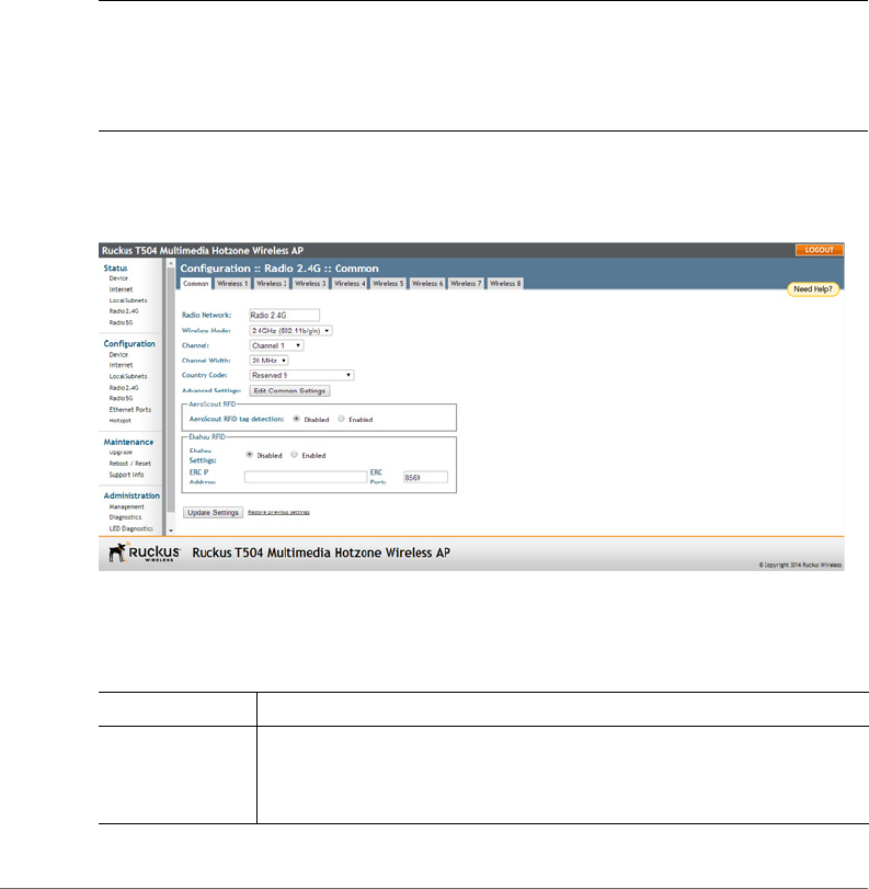
Configuring Common Wireless Settings
The settings on the Common page are required to enable wireless devices to
associate with the AP.
NOTE The AP has one 2.4GHz radio and one 5GHz radio. The wireless settings
for each radio need to be configured separately on the Web interface. To configure
the 2.4GHz radio settings, click Configuration > Radio 2.4G. To configure the 5GHz
radio settings, click Configuration > Radio 5G.
1On the left menu of the Web interface, click Configuration > Radio {2.4G/5G}.
The Common page appears (Figure 15).
Figure 15. The Configuration > Radio 2.4 > Common Page
2Verify that the common wireless settings are configured as listed in Tab l e 8.
Table 8. Common wireless configuration
Setting Recommended Value
Wireless Mode • 2.4GHz (802.11b/g/n) for Configuration > Radio 2.4G >
Common.
•5GHz (802.11ac/a/n) for Configuration > Radio 5G > Common.
DRAFT

Installing the T504
Deploying the T504
T504 Strand Mount Concurrent AP with Integrated CM Installation Guide, 800-70610-001 Rev A 36
3If you made any changes to the Common page, then click Update Settings.
4Repeat Step 1 through Step 3 for Configuration > Radio 5G.
Continue with Configuring Wireless LAN Settings.
Configuring Wireless LAN Settings
The settings on at least one Wireless # (Wireless LAN Number) page are required
to enable wireless devices to associate with the AP. The default wireless settings
are listed in Tab le 9 .
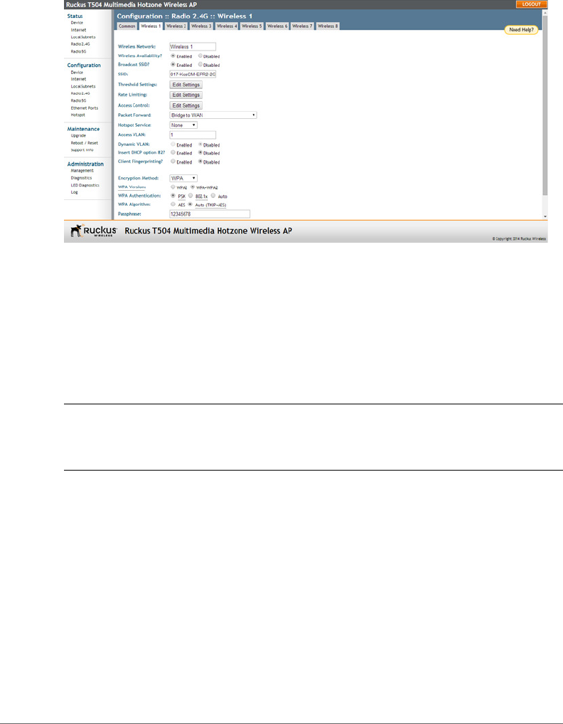
1Click one of the Wireless # tabs. The selected Wireless # page appears (Figure
16).
Channel SmartSelect.
Channel Width 20 MHz.
Country Code • If you purchased the AP in the United States of America, this value
is fixed to United States at the factory and is not user
configurable.
• If you purchased the AP outside the United States of America, verify
that the value is set to your country or region. Selecting the correct
country code ensures that the AP uses only the radio channels
allowed in your country or region.
NOTE: The two radios on the Ruckus Wireless AP are always
configured with the same country code setting. If you change the
country code for Radio 2.4G, for example, the same change is
automatically applied to Radio 5G.
Table 9. Default wireless settings
Setting Default Value
SSID (network name) Wireless 1 to Wireless 8 (8 WLANs)
Encryption Method (security) Disabled on all WLANs
Table 8. Common wireless configuration (Continued)
Setting Recommended Value
DRAFT
Installing the T504
Verifying CM and AP Operation
T504 Strand Mount Concurrent AP with Integrated CM Installation Guide, 800-70610-001 Rev A 37
Figure 16. The Configuration > Radio 2.4 > Wireless 1 Page
2In Wireless Availability, click Enabled.
3In Broadcast SSID, click Enabled.
4Clear the SSID box, and then type a unique and descriptive name that you want
to call this wireless network.
For example, you can type Ruckus Wireless AP. This SSID is the name that
helps users identify this wireless network in their wireless network connection
application.
NOTE You can also configure other wireless settings on this and other Wireless
# pages (in addition to the settings described above), although it is not necessary
for completing the AP installation.
5Click Update Settings. You have completed configuring the basic wireless
settings of the AP.
6Continue with Verifying CM and AP Operation.
Verifying CM and AP Operation
The cable operator has their own CM and AP acceptance tests. Make sure you
verify the T504 operation as defined in the acceptance tests before leaving the
installation site.
DRAFT

T504 Strand Mount Concurrent AP with Integrated CM Installation Guide, 800-70610-001 Rev A 38
4
Operating and Troubleshooting the
T504
This section lists some information that may be useful in operating and trouble-
shooting the T504. Topics discussed include:
•Retrieving the CM’s MAC Address
•Rebooting and Resetting the T504
•How Radio Frequency Scanning Works
Retrieving the CM’s MAC Address
There are some configuration operations that require you to enter the CM’s MAC
address. The CM and AP MAC addresses are printed on labels on the outside of
the T504, as described in Finding the AP and CM MAC Addresses.
Retrieving the CM’s MAC Address
There are some configuration operations that require you to enter the CM’s MAC
address. The CM and AP MAC addresses are printed on labels on the outside of
the T504, as described in Finding the AP and CM MAC Addresses.
If you cannot find the CM’s MAC address on the T504, you can retrieve it via the
CMTS using the AP and CM command line interfaces:
•Retrieving the CM’s MAC Address using the CM CLI
•Retrieving the CM’s MAC Address using the AP CLI
Retrieving the CM’s MAC Address using the CM CLI
Use CM command line interface via the CMTS to retrieve the CM’s MAC address.
1Obtain the IP address assigned to the CM. You can obtain this information from
the DHCP server at the CMTS.
2Connect an administrative computer to the same subnet as the T504.
3Start the Telnet or SSH client program on the administrative computer.
4Log onto the CM using Telnet or SSH with the following logon details:
•User name: super
DRAFT

Operating and Troubleshooting the T504
Rebooting and Resetting the T504
T504 Strand Mount Concurrent AP with Integrated CM Installation Guide, 800-70610-001 Rev A 39
• Password: mso-admin
5When the command prompt appears, enter the following command:
cd n
cd hal
mac_address 1
The CLI displays the CM’s MAC address.
Retrieving the CM’s MAC Address using the AP CLI
Use AP command line interface via the CMTS to retrieve the CM’s MAC address.
1Obtain the IP address assigned to the AP. You can obtain this information from
the DHCP server at the CMTS.
2Connect an administrative computer to the same subnet as the T504.
3On the administrative computer, start the Telnet or SSH (secure shell) client
program.
4Log onto to the AP using Telnet or SSH with the following logon details:
•User names: super
• Password: sp-admin
5When command prompt appears, enter the following command:
get cm supportinfo
### Basic Info ###
MAC Address: C0 xx xx xx xx xx
Software Version: V9xxxx
WAN IP Address: 10.225.xxx.xxx
The command prompt displays the CM’s MAC address.
Rebooting and Resetting the T504
Refer to Rebooting and Resetting the AP and CM for instructions on rebooting and
resetting the AP and CM parts of the T504.
DRAFT

Operating and Troubleshooting the T504
How Radio Frequency Scanning Works
T504 Strand Mount Concurrent AP with Integrated CM Installation Guide, 800-70610-001 Rev A 40
How Radio Frequency Scanning Works
The following steps describe how a DOCSIS-compliant T504 performs radio
frequency scanning:
1Looks at the last “known good channel” (repeat this every 64 channel checks).
2Checks the sixteen last known frequencies (repeat this every 32 channel checks).
3Scans STD standard channels (where the center of the channel is an integer
spaced by 6MHz), first [from 93MHz to 999MHz - 152 channels]).
4Scans the harmonically related carrier (HRC) channels, which moves the
channels 1.25MHz off the standard frequencies so the video carriers are all
related by 6MHz [from 91.75 to 997.5MHz--152 channels].
A complete frequency scan requires approximately 469 channel checks. Since each
channel takes about 0.6 seconds, a full scan is done every 281 seconds (a little
under 5 minutes).
NOTE The scanning of generic DOCSIS channels is required the first time the T504
connects to an MSO. After the initial scan, the T504 is able to retrieve the local
country frequency plan without a complete scan during its normal operation.
DRAFT

T504 Strand Mount Concurrent AP with Integrated CM Installation Guide, 800-70610-001 Rev A 41
5
What to Do Next
The following are some of the post-installation tasks that Ruckus Wireless recom-
mends. Refer to the Ruckus Wireless Outdoor Access Point User Guide for more
information on configuring and managing the AP.
Changing the Administrative Password
Management access to the Web interface of the AP is controlled through adminis-
trative user name and password. As soon as you complete the AP setup, make
sure you log on to the AP’s Web interface and change the default administrative
user name and password. This will help prevent unauthorized users from logging in
to the AP’s Web interface and changing the AP settings to compromise your
network.
Configuring the Security Settings
Unlike wired networks, anyone with a compatible wireless adapter can receive
wireless data transmissions from your network. To prevent unauthorized users from
entering your wireless network and accessing your computers and files, Ruckus
Wireless strongly recommends enabling and configuring wireless security on the
AP. The AP supports several types of encryption and authentication methods to
help prevent unauthorized access to your wireless network.
Configuring Advanced Settings and Features
The AP has been configured for basic operation. However, the Ruckus Wireless AP
supports many advanced settings and features. Refer to the Ruckus Wireless
Outdoor Access Point User Guide for instructions on how to configure the advanced
setting and feature parameters.
Reading Related Documentation
The latest versions of Ruckus Wireless product documentation are available for
download on the Ruckus Wireless Support Web site at
http://support.ruckuswireless.com/documents
DRAFT

T504 Strand Mount Concurrent AP with Integrated CM Installation Guide, 800-70610-001 Rev A 42
A
Appendix A: Ruckus Wireless
Factory- and Customer-Supplied
Parts
Table 10. Factory-supplied and customer-supplied parts
Part Ruckus Wireless
P/N
T504 Kit or
Customer
Supplied
Notes
1m lugged earth
ground wire
741-65006-001 T504 kit
Cable power tap
and connecting
cable
-- Customer
supplied
Antronix
MGT2000-SDPE
tap, or equivalent
DRAFT

T504 Strand Mount Concurrent AP with Integrated CM Installation Guide, 800-70610-001 Rev A 43
B
Appendix B: Rebooting and
Resetting the T504
•Rebooting and Resetting the AP and CM
•Resetting the CM to Factory Default Settings
Rebooting and Resetting the AP and CM
CAUTION! Performing this procedure resets the AP and CM parts of the T504 to
their factory default settings.
If you want to reset only the CM component to its factory default settings, then
perform the procedure described in “Resetting the CM to Factory Default Settings”
on page 45 instead.
CAUTION! Resetting the AP and CM to factory default settings erases all the
settings that you have previously configured. Also note that resetting and/or
rebooting the AP and CM disrupts all wireless network communications through
this device.
There are different ways to reboot or reset the AP and CM parts of the T504:
•Using the Reset Button Inside the AP
•Remotely Rebooting the AP
Using the Reset Button Inside the AP
You can reset the AP and CM to their factory default settings by pressing the reset
button located under the Reset button and diagnostic Ethernet port blanking cap
on the T504.
1Make sure that the AP is powered.
2Use a 7/16” (11mm) socket to remove the Reset button and diagnostic Ethernet
port cap. See Figure 5 for the location of the Reset button and diagnostic
Ethernet port cap.
3Locate the reset button under the Reset button and diagnostic Ethernet port
cap. See Figure 17 for the location of the reset button inside the T504.
DRAFT
Rebooting and Resetting the AP and CM
T504 Strand Mount Concurrent AP with Integrated CM Installation Guide, 800-70610-001 Rev A 44
Figure 17. Location of the reset button
4Using a pen or a similar pointed object, momentarily press the reset button on
the reset adapter assembly to reboot the AP and CM, or hold the reset button
for 10 seconds to reset the AP and CM to factory defaults.
5Replace the Reset button and diagnostic Ethernet port cap.
You have completed resetting the AP and CM to their factory default settings and/
or rebooting the AP and CM.
Remotely Rebooting the AP
NOTE Before starting this procedure, you must first obtain the related MIBs from
Ruckus Wireless. Contact your authorized Ruckus Wireless sales representative or
Ruckus Wireless Support. Visit http://support.ruckuswireless.com/
contacts for Ruckus Wireless Support contact information (login required).
1Connect the administrative computer to the same network as the T504.
2Start your MIB browser.
3Load the Ruckus Wireless MIBs onto the MIB browser.
4In the MIB browser, specify the IP address of the T504 AP. (You can obtain this
information from the DHCP server on the network.)
5Find the OID 1.3.6.1.4.1.25053.3.1.4.7.3 (ruckusZFT504ControlLED).
6Set the value to 14 (powerCycleAP).
You have completed remotely rebooting the access point using SNMP.
DRAFT

Resetting the CM to Factory Default Settings
T504 Strand Mount Concurrent AP with Integrated CM Installation Guide, 800-70610-001 Rev A 45
Resetting the CM to Factory Default Settings
CAUTION! Performing this procedure resets the CM part of the T504 to its factory
default settings.
If you want to reset the AP and CM components to their factory default settings,
then perform the procedure described in “Rebooting and Resetting the AP and CM”
on page 43 instead.
You can use SNMP on either the access point or cable modem to reset the CM to
factory default settings. The procedure is the same, regardless whether you perform
this operation from the AP or CM.
NOTE Before starting this procedure, you must first obtain the related MIBs from
Ruckus Wireless. Contact your authorized Ruckus Wireless sales representative or
Ruckus Wireless Support. Visit http://support.ruckuswireless.com/
contacts for Ruckus Wireless Support contact information (login required).
1Connect the administrative computer to the same network as the T504.
2Start your MIB browser.
3Load the Ruckus Wireless MIBs onto the MIB browser.
4In the MIB browser, specify the IP address of the T504 access point or cable
modem. (You can obtain this information from the DHCP server on the network.)
5Find the OID 1.3.6.1.4.1.25053.3.1.4.7.3 (ruckusZFT504ControlLED).
6Set the value to 15 (factoryResetCM).
You have completed resetting the cable modem to factory default settings using
SNMP.
DRAFT
T504 Strand Mount Concurrent AP with Integrated CM Installation Guide, 800-70610-001 Rev A 46
C
Appendix C: T504 Mounting
Dimensions and Weight
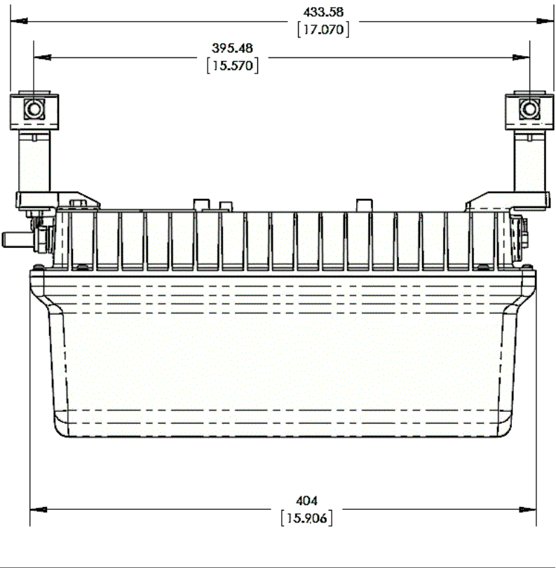
Dimensions
Figure 18. T504 length--all dimensions in millimeters and [inches]
DRAFT
Dimensions
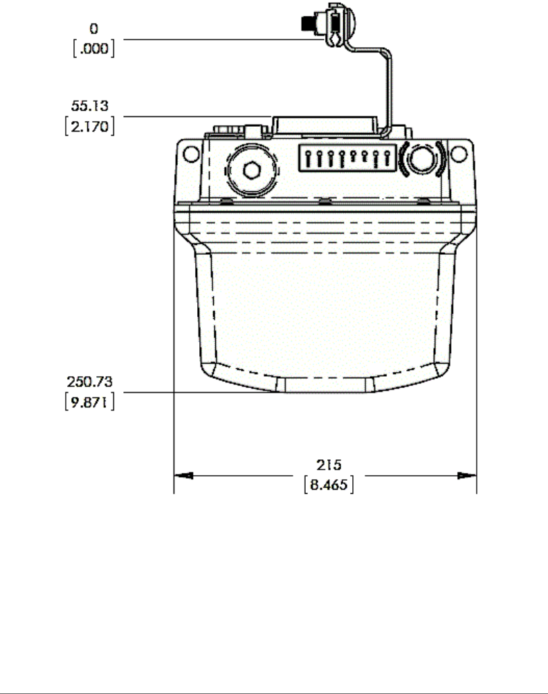
T504 Strand Mount Concurrent AP with Integrated CM Installation Guide, 800-70610-001 Rev A 47
Figure 19. T504 height and width--all dimensions in millimeters and [inches]
DRAFT

Weight
T504 Strand Mount Concurrent AP with Integrated CM Installation Guide, 800-70610-001 Rev A 48
Weight
The T504 weighs 9.5 pounds. For other specifications, refer to the Ruckus Wireless
data sheet.
DRAFT

Copyright © 2006-2014. Ruckus Wireless, Inc.
350 West Java Dr. Sunnyvale, CA 94089. USA
www.ruckuswireless.com
DRAFT