Ruckus Wireless ZF7761CM Dual-Band 802.11 a/b/g/n Industrial Access Point User Manual 800 70290 001
Ruckus Wireless, Inc. Dual-Band 802.11 a/b/g/n Industrial Access Point 800 70290 001
Contents
- 1. User Manual 1 of 2
- 2. User Manual 2 of 2
User Manual 1 of 2
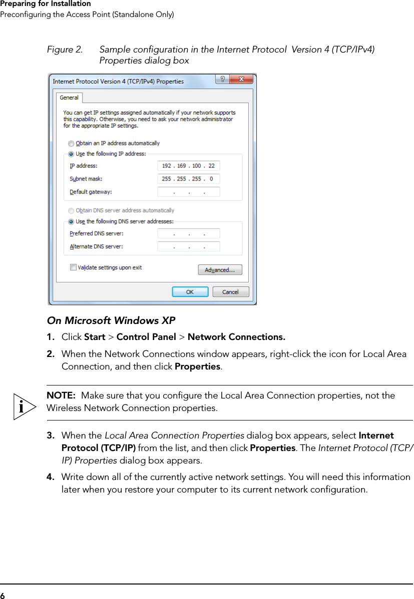
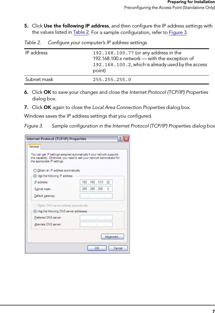
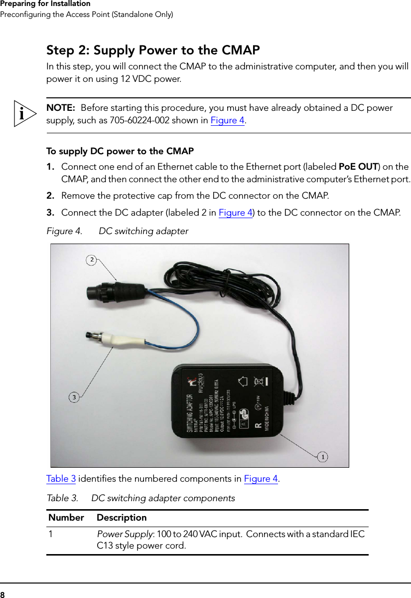
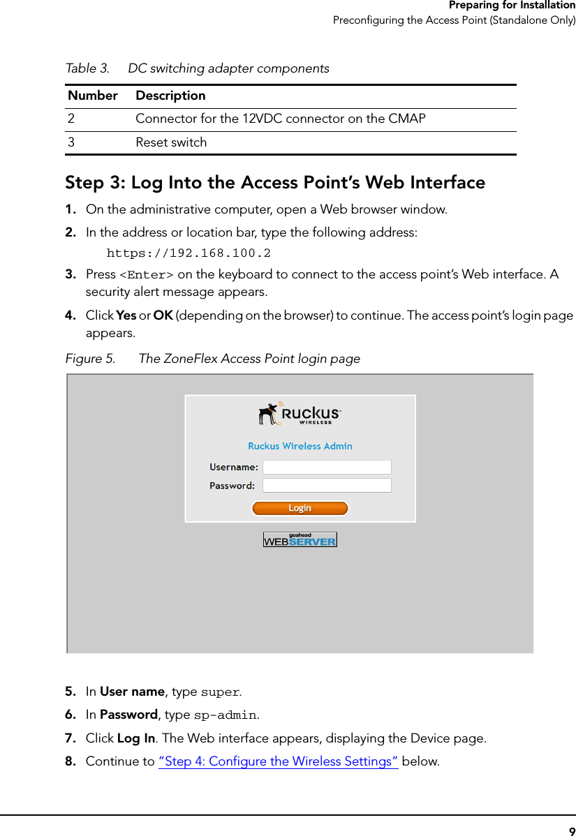
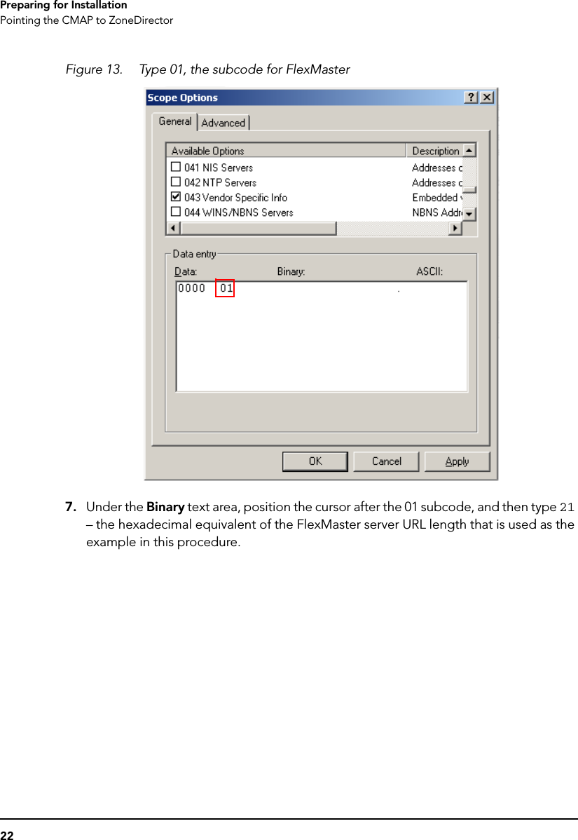
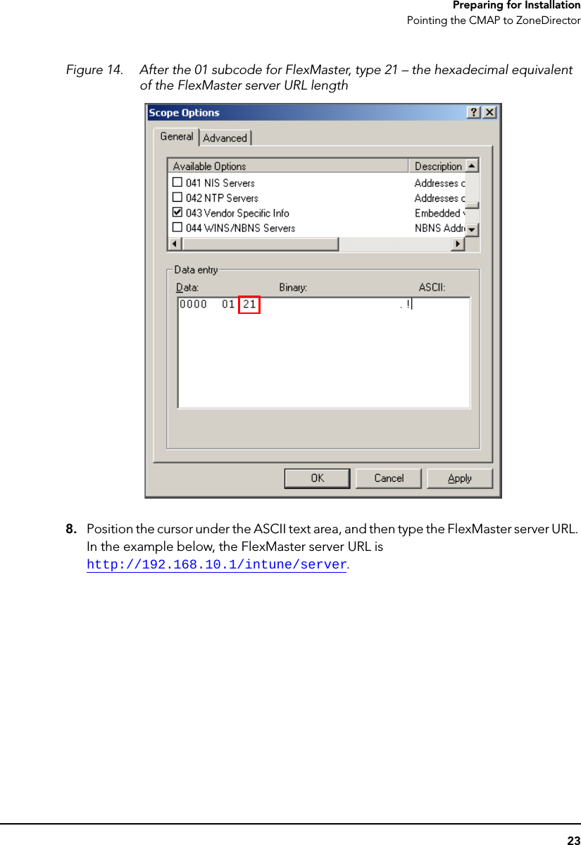
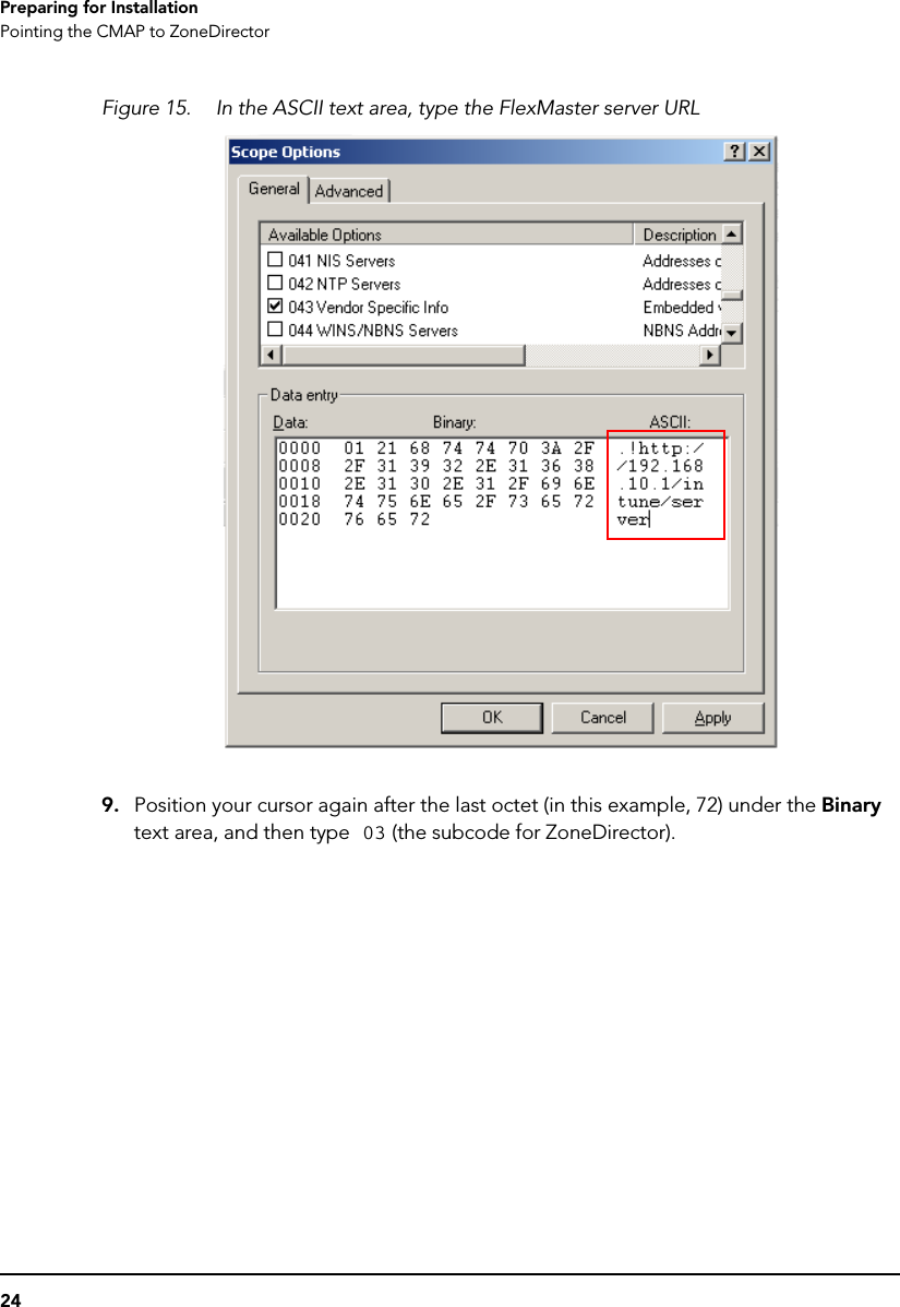
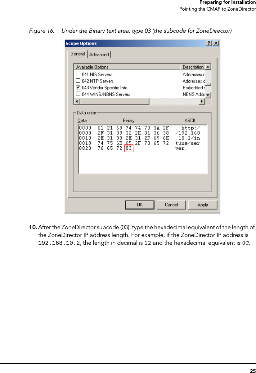
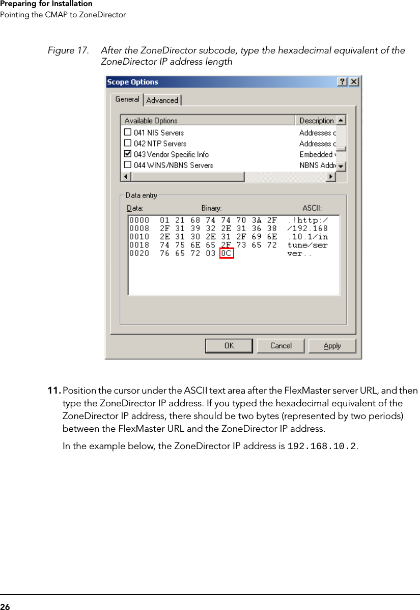
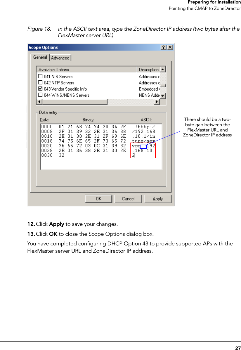
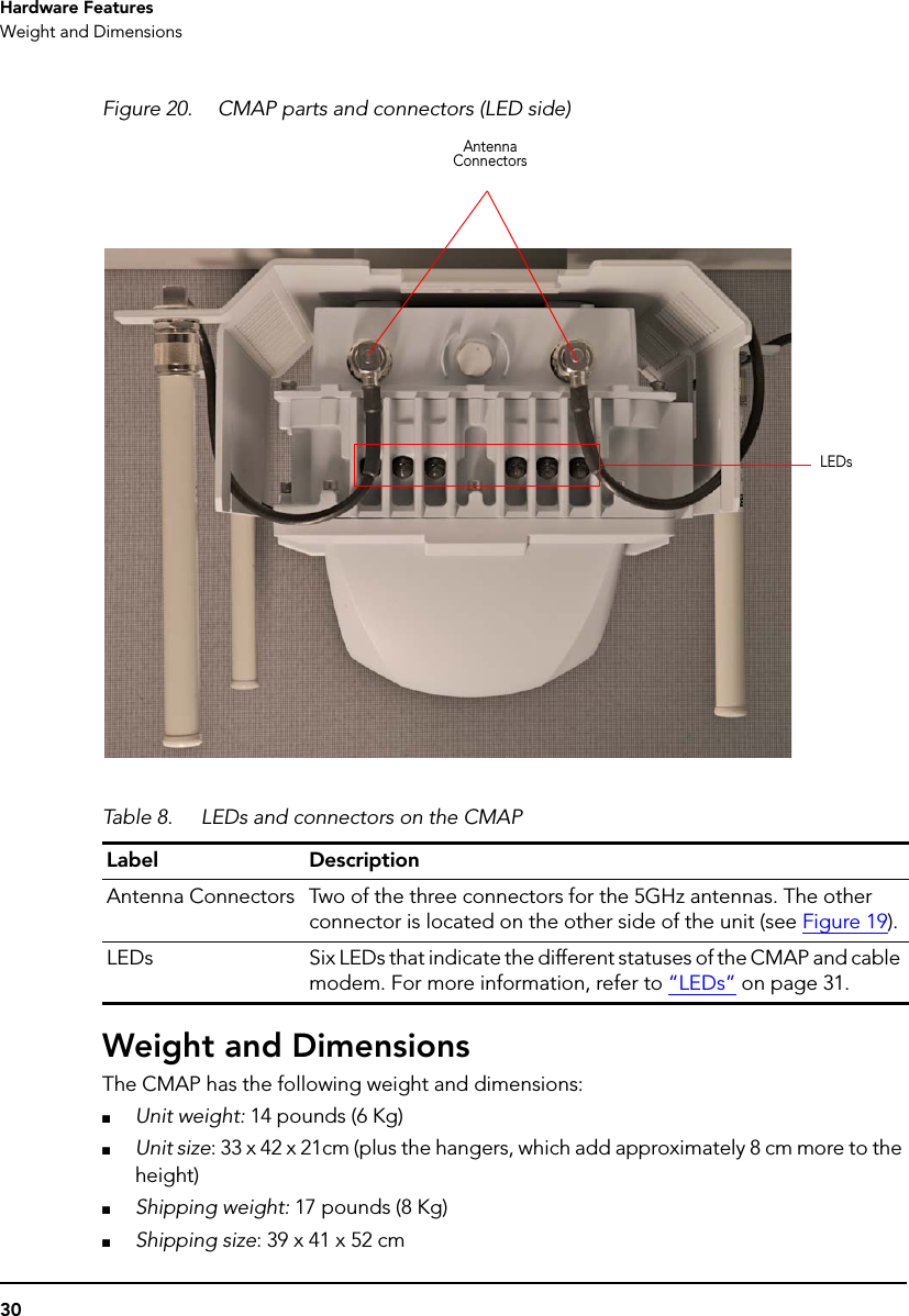
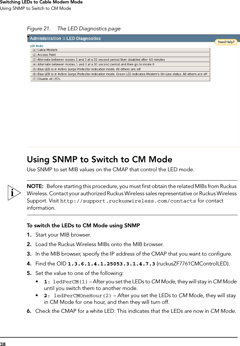
![47TroubleshootingHow Radio Frequency Scanning Works■An Ethernet cable■A Telnet or SSH (secure shell) client programDo the following1. Connect one end of the Ethernet cable to the administrative computer’s Ethernet port, and then connect the other end to the CMAP’s Ethernet port.2. Change the administrative computer’s IP address to the same subnet as the CMAP. The CM’s default IP address is 192.168.100.1.3. Start the Telnet or SSH client program on the administrative computer.4. Log onto to the CM via Telnet or SSH using the following logon details:•User name: super•Password: mso-admin5. When the command prompt appears, enter the following command:cd ncd halmac_address 1The command prompt displays the CM’s MAC address.How Radio Frequency Scanning WorksTo perform radio frequency scanning, the AP does the following:1. Looks at the last “known good channel” (repeat this every 64 channel checks).2. Checks the sixteen last known frequencies (repeat this every 32 channel checks).3. Scans standard channels (where the center of the channel is an integer spaced by 6 MHz), first [from 94.25 MHz to 1001.25 MHz - 152 channels]).4. Scans the harmonically related carriers (HRC) channels, which moves the channels 1.25 MHz off the standard frequencies so the video carriers are all related by 6 MHz [from 93 to 999 MHz - 152 channels].A complete frequency scan requires approximately 469 channel checks. Since each channel takes about 0.6 seconds, a full scan is done every 281 second (a little under 5 minutes).Contacting Ruckus Wireless SupportFor assistance in troubleshooting other issues that are not described in this guide, contact Ruckus Wireless technical support (see below):■Email: support@ruckuswireless.com■Web Site: http://support.ruckuswireless.com/](https://usermanual.wiki/Ruckus-Wireless/ZF7761CM.User-Manual-1-of-2/User-Guide-1430180-Page-51.png)