Ruckus Brocade FCX Series Hardware Installation Guide Fast Iron CX Fastiron Installguide
FastIron CX Series Hardware Installation Guide fastiron-cx-installguide
2017-06-15
User Manual: Ruckus FastIron CX Series Hardware Installation Guide
Open the PDF directly: View PDF ![]() .
.
Page Count: 108 [warning: Documents this large are best viewed by clicking the View PDF Link!]
- Brocade FCX Series Hardware Installation Guide
- Preface
- About This Document
- Product Overview
- Hardware features
- Control features
- Serial management interface (DB-9 Console port)
- Out-of-band RJ-45 management interface
- Network interfaces for Brocade FCX 624S, FCX 648S, FCX 624S-F, FCX 624S-HPOE, and FCX 648S-HPOE
- Network interfaces for Brocade FCX 624-E, FCX 624-I, FCX 648-E, and FCX 648-I
- SFP interfaces
- Optional two-port 10 Gbps XFP uplink module
- Optional 4x1G SFP+ and 4x10G SFP+ modules
- 16/10 Gbps Ethernet CX4 stacking module
- Optional 2-port 10 Gbps SFP+ uplink module
- Specifying a port address
- –Port, system, and power status LEDs for Brocade FCX 624S, FCX 648S, FCX 624S-F, FCX 624S-HPOE, and FCX 648S-HPOE
- Port, system, and power status LEDs for Brocade FCX 624-E, FCX 624-I, FCX 648-E, and FCX 648-I
- Power supplies
- Control features
- Hardware features
- Installing the FCX Switch
- Checking Network Devices and Testing Connectivity
- Assigning permanent passwords
- Configuring IP addresses
- Devices running Layer 2 software
- Devices running Layer 3 software
- Performing a factory reset
- Connecting network devices
- Connectors
- Cable specifications
- Cable specifications
- Connecting to Ethernet or Fast Ethernet hubs
- Connecting to workstations, servers, or routers
- Connecting a network device to a fiber port
- Testing connectivity
- Troubleshooting network connections
- Managing the FCX Hardware
- Brocade FCX Series Technical Specifications
- System specifications
- Ethernet
- LEDs
- Other
- Weight and physical dimensions
- Environmental requirements
- Power supply specifications (per PSU)
- Power consumption (maximum configuration)
- Data port specifications (Ethernet)
- Serial port specifications (DB9)
- Serial port specifications (pinout RJ-45)
- Serial port specifications (protocol)
- Regulatory compliance (EMC)
- Regulatory compliance (safety)
- Regulatory compliance (environmental)
- Troubleshooting
- Regulatory Statements
- Cautions and Danger Notices

HARDWARE INSTALLATION GUIDE
Brocade FCX Series
Hardware Installation Guide
Part Number: 53-1003616-03
Publication Date: 15 June 2017
© 2017, Brocade Communications Systems, Inc. All Rights Reserved.
Brocade, the B-wing symbol, and MyBrocade are registered trademarks of Brocade Communications Systems, Inc., in the United States and in other
countries. Other brands, product names, or service names mentioned of Brocade Communications Systems, Inc. are listed at www.brocade.com/en/legal/
brocade-Legal-intellectual-property/brocade-legal-trademarks.html. Other marks may belong to third parties.
Notice: This document is for informational purposes only and does not set forth any warranty, expressed or implied, concerning any equipment,
equipment feature, or service oered or to be oered by Brocade. Brocade reserves the right to make changes to this document at any time, without
notice, and assumes no responsibility for its use. This informational document describes features that may not be currently available. Contact a Brocade
sales oce for information on feature and product availability. Export of technical data contained in this document may require an export license from the
United States government.
The authors and Brocade Communications Systems, Inc. assume no liability or responsibility to any person or entity with respect to the accuracy of this
document or any loss, cost, liability, or damages arising from the information contained herein or the computer programs that accompany it.
The product described by this document may contain open source software covered by the GNU General Public License or other open source license
agreements. To nd out which open source software is included in Brocade products, view the licensing terms applicable to the open source software, and
obtain a copy of the programming source code, please visit http://www.brocade.com/support/oscd.
Brocade FCX Series Hardware Installation Guide
2 Part Number: 53-1003616-03

Contents
Preface...................................................................................................................................................................................................................................7
Document conventions............................................................................................................................................................................................................................7
Notes, cautions, and warnings.....................................................................................................................................................................................................7
Text formatting conventions.........................................................................................................................................................................................................7
Command syntax conventions....................................................................................................................................................................................................8
Brocade resources.....................................................................................................................................................................................................................................8
Document feedback..................................................................................................................................................................................................................................8
Contacting Brocade Technical Support............................................................................................................................................................................................ 9
Brocade customers..........................................................................................................................................................................................................................9
Brocade OEM customers............................................................................................................................................................................................................. 9
About This Document..................................................................................................................................................................................................... 11
What’s new in this document ............................................................................................................................................................................................................11
Supported Software............................................................................................................................................................................................................................... 11
Product Overview.............................................................................................................................................................................................................13
Hardware features................................................................................................................................................................................................................................... 13
Control features.............................................................................................................................................................................................................................. 16
Power supplies................................................................................................................................................................................................................................31
Installing the FCX Switch................................................................................................................................................................................................ 33
Unpacking the device............................................................................................................................................................................................................................33
Package contents...........................................................................................................................................................................................................................33
General requirements...................................................................................................................................................................................................................33
Installation tasks.......................................................................................................................................................................................................................................34
Installation precautions......................................................................................................................................................................................................................... 34
General precautions......................................................................................................................................................................................................................34
Lifting precautions.........................................................................................................................................................................................................................35
Power precautions.........................................................................................................................................................................................................................35
Preparing the installation site..............................................................................................................................................................................................................35
Cabling infrastructure...................................................................................................................................................................................................................35
Installation location........................................................................................................................................................................................................................36
Installing the device.......................................................................................................................................................................................................................36
Desktop installation.......................................................................................................................................................................................................................37
Rack mount installation...............................................................................................................................................................................................................37
Connecting devices in a traditional stack...................................................................................................................................................................................... 41
Stacking ports................................................................................................................................................................................................................................. 42
Stacking conguration requirements.....................................................................................................................................................................................43
Stacking cables...............................................................................................................................................................................................................................44
Stack size.......................................................................................................................................................................................................................................... 44
Stacking topologies...................................................................................................................................................................................................................... 44
Extended distance stacking.......................................................................................................................................................................................................47
Powering on the system.......................................................................................................................................................................................................................47
Attaching a PC or terminal.................................................................................................................................................................................................................. 48
Wiring map for serial cable........................................................................................................................................................................................................ 49
Installing and replacing a power supply unit................................................................................................................................................................................ 50
Installing or replacing fan trays.......................................................................................................................................................................................................... 50
Installing an optional module ............................................................................................................................................................................................................ 52
Brocade FCX Series Hardware Installation Guide
Part Number: 53-1003616-03 3
Optional 2-port 10 Gbps SFP+ uplink module............................................................................................................................................................... 54
Checking Network Devices and Testing Connectivity.............................................................................................................................................. 59
Assigning permanent passwords.....................................................................................................................................................................................................59
Setting passwords......................................................................................................................................................................................................................... 59
Recovering from a lost password............................................................................................................................................................................................60
Conguring IP addresses.................................................................................................................................................................................................................... 60
Devices running Layer 2 software..........................................................................................................................................................................................61
Devices running Layer 3 software..........................................................................................................................................................................................62
Performing a factory reset..........................................................................................................................................................................................................65
Connecting network devices.....................................................................................................................................................................................................65
Connectors....................................................................................................................................................................................................................................... 65
Cable specications......................................................................................................................................................................................................................65
Cable specications......................................................................................................................................................................................................................66
Connecting to Ethernet or Fast Ethernet hubs..................................................................................................................................................................66
Connecting to workstations, servers, or routers................................................................................................................................................................68
Connecting a network device to a ber port.......................................................................................................................................................................68
Testing connectivity................................................................................................................................................................................................................................72
Pinging an IP address..................................................................................................................................................................................................................72
Observing LEDs............................................................................................................................................................................................................................ 72
Tracing a route.................................................................................................................................................................................................................................76
Troubleshooting network connections........................................................................................................................................................................................... 76
Digital optical monitoring............................................................................................................................................................................................................77
Virtual cable testing.......................................................................................................................................................................................................................77
Managing the FCX Hardware.........................................................................................................................................................................................81
Managing temperature settings........................................................................................................................................................................................................ 81
Using the temperature sensor..................................................................................................................................................................................................81
Removing MAC address entries..............................................................................................................................................................................................84
Displaying FCX CPU usage............................................................................................................................................................................................................... 85
Hardware maintenance schedule..................................................................................................................................................................................................... 85
Replacing a copper or ber optic module.....................................................................................................................................................................................85
Removing a copper or ber optic module.......................................................................................................................................................................... 85
Cabling a ber optic module.....................................................................................................................................................................................................86
Cleaning the ber optic connectors....................................................................................................................................................................................... 87
Brocade FCX Series Technical Specications............................................................................................................................................................89
System specications............................................................................................................................................................................................................................89
Ethernet.......................................................................................................................................................................................................................................................89
LEDs.............................................................................................................................................................................................................................................................89
Other............................................................................................................................................................................................................................................................ 90
Weight and physical dimensions...................................................................................................................................................................................................... 90
Environmental requirements.............................................................................................................................................................................................................. 90
Power supply specications (per PSU)..........................................................................................................................................................................................91
Power consumption (maximum conguration)...........................................................................................................................................................................91
Data port specications (Ethernet)...................................................................................................................................................................................................92
Serial port specications (DB9).........................................................................................................................................................................................................93
Serial port specications (pinout RJ-45).......................................................................................................................................................................................93
Serial port specications (protocol)..................................................................................................................................................................................................94
Regulatory compliance (EMC)...........................................................................................................................................................................................................94
Regulatory compliance (safety)..........................................................................................................................................................................................................94
Regulatory compliance (environmental).........................................................................................................................................................................................94
Brocade FCX Series Hardware Installation Guide
4 Part Number: 53-1003616-03
Troubleshooting ...............................................................................................................................................................................................................97
Diagnosing switch indicators .............................................................................................................................................................................................................97
Power and cooling problems....................................................................................................................................................................................................97
Installation......................................................................................................................................................................................................................................... 97
In-band access............................................................................................................................................................................................................................... 97
Regulatory Statements....................................................................................................................................................................................................99
CE Statement............................................................................................................................................................................................................................................99
China ROHS............................................................................................................................................................................................................................................. 99
BSMI statement (Taiwan).....................................................................................................................................................................................................................99
Canadian requirements......................................................................................................................................................................................................................100
China CC statement............................................................................................................................................................................................................................100
Europe and Australia (CISPR 22 Class A Warning)...............................................................................................................................................................101
FCC warning (US only)...................................................................................................................................................................................................................... 101
Germany.................................................................................................................................................................................................................................................. 101
KCC statement (Republic of Korea).............................................................................................................................................................................................. 101
VCCI statement.....................................................................................................................................................................................................................................101
Cautions and Danger Notices..................................................................................................................................................................................... 103
Cautions...................................................................................................................................................................................................................................................103
General cautions......................................................................................................................................................................................................................... 103
Electrical cautions.......................................................................................................................................................................................................................105
Danger Notices.....................................................................................................................................................................................................................................106
General dangers..........................................................................................................................................................................................................................106
Electrical dangers........................................................................................................................................................................................................................106
Dangers related to equipment weight................................................................................................................................................................................108
Laser dangers.............................................................................................................................................................................................................................. 108
Brocade FCX Series Hardware Installation Guide
Part Number: 53-1003616-03 5
Brocade FCX Series Hardware Installation Guide
6 Part Number: 53-1003616-03

Preface
• Document conventions...................................................................................................................................................................................... 7
• Brocade resources............................................................................................................................................................................................... 8
• Document feedback............................................................................................................................................................................................8
• Contacting Brocade Technical Support.......................................................................................................................................................9
Document conventions
The document conventions describe text formatting conventions, command syntax conventions, and important notice formats used in
Brocade technical documentation.
Notes, cautions, and warnings
Notes, cautions, and warning statements may be used in this document. They are listed in the order of increasing severity of potential
hazards.
NOTE
A Note provides a tip, guidance, or advice, emphasizes important information, or provides a reference to related information.
ATTENTION
An Attention statement indicates a stronger note, for example, to alert you when trac might be interrupted or the device might
reboot.
CAUTION
A Caution statement alerts you to situations that can be potentially hazardous to you or cause damage to hardware,
rmware, software, or data.
DANGER
A Danger statement indicates conditions or situations that can be potentially lethal or extremely hazardous to you. Safety
labels are also attached directly to products to warn of these conditions or situations.
Text formatting conventions
Text formatting conventions such as boldface, italic, or Courier font may be used to highlight specic words or phrases.
Format Description
bold text Identies command names.
Identies keywords and operands.
Identies the names of GUI elements.
Identies text to enter in the GUI.
italic text Identies emphasis.
Identies variables.
Identies document titles.
Courier font Identies CLI output.
Brocade FCX Series Hardware Installation Guide
Part Number: 53-1003616-03 7
Format Description
Identies command syntax examples.
Command syntax conventions
Bold and italic text identify command syntax components. Delimiters and operators dene groupings of parameters and their logical
relationships.
Convention Description
bold text Identies command names, keywords, and command options.
italic text Identies a variable.
value In Fibre Channel products, a xed value provided as input to a command option is printed in plain text, for
example, --show WWN.
[ ] Syntax components displayed within square brackets are optional.
Default responses to system prompts are enclosed in square brackets.
{ x | y | z } A choice of required parameters is enclosed in curly brackets separated by vertical bars. You must select
one of the options.
In Fibre Channel products, square brackets may be used instead for this purpose.
x | yA vertical bar separates mutually exclusive elements.
< > Nonprinting characters, for example, passwords, are enclosed in angle brackets.
... Repeat the previous element, for example, member[member...].
\ Indicates a “soft” line break in command examples. If a backslash separates two lines of a command
input, enter the entire command at the prompt without the backslash.
Brocade resources
Visit the Brocade website to locate related documentation for your product and additional Brocade resources.
White papers, data sheets, and the most recent versions of Brocade software and hardware manuals are available at www.brocade.com.
Product documentation for all supported releases is available to registered users at MyBrocade.
Click the Support tab and select Document Library to access product documentation on MyBrocade or www.brocade.com. You can
locate documentation by product or by operating system.
Release notes are bundled with software downloads on MyBrocade. Links to software downloads are available on the MyBrocade landing
page and in the Document Library.
Document feedback
Quality is our rst concern at Brocade, and we have made every eort to ensure the accuracy and completeness of this document.
However, if you nd an error or an omission, or you think that a topic needs further development, we want to hear from you. You can
provide feedback in two ways:
• Through the online feedback form in the HTML documents posted on www.brocade.com
• By sending your feedback to documentation@brocade.com
Provide the publication title, part number, and as much detail as possible, including the topic heading and page number if applicable, as
well as your suggestions for improvement.
Brocade resources
Brocade FCX Series Hardware Installation Guide
8 Part Number: 53-1003616-03

Contacting Brocade Technical Support
As a Brocade customer, you can contact Brocade Technical Support 24x7 online or by telephone. Brocade OEM customers should
contact their OEM/solution provider.
Brocade customers
For product support information and the latest information on contacting the Technical Assistance Center, go to www.brocade.com and
select Support.
If you have purchased Brocade product support directly from Brocade, use one of the following methods to contact the Brocade
Technical Assistance Center 24x7.
Online Telephone
Preferred method of contact for non-urgent issues:
• Case management through the MyBrocade portal.
• Quick Access links to Knowledge Base, Community, Document
Library, Software Downloads and Licensing tools
Required for Sev 1-Critical and Sev 2-High issues:
• Continental US: 1-800-752-8061
• Europe, Middle East, Africa, and Asia Pacic: +800-AT FIBREE
(+800 28 34 27 33)
•Toll-free numbers are available in many countries.
• For areas unable to access a toll-free number:
+1-408-333-6061
Brocade OEM customers
If you have purchased Brocade product support from a Brocade OEM/solution provider, contact your OEM/solution provider for all of
your product support needs.
• OEM/solution providers are trained and certied by Brocade to support Brocade® products.
• Brocade provides backline support for issues that cannot be resolved by the OEM/solution provider.
• Brocade Supplemental Support augments your existing OEM support contract, providing direct access to Brocade expertise.
For more information, contact Brocade or your OEM.
• For questions regarding service levels and response times, contact your OEM/solution provider.
Contacting Brocade Technical Support
Brocade FCX Series Hardware Installation Guide
Part Number: 53-1003616-03 9
Brocade FCX Series Hardware Installation Guide
10 Part Number: 53-1003616-03

About This Document
• What’s new in this document .......................................................................................................................................................................11
• Supported Software..........................................................................................................................................................................................11
What’s new in this document
There are no enhancements in this edition.
Supported Software
For information about the features supported on a hardware platform, refer to the appropriate Features and Standards Support Matrix
document.
Brocade FCX Series Hardware Installation Guide
Part Number: 53-1003616-03 11
Brocade FCX Series Hardware Installation Guide
12 Part Number: 53-1003616-03

Product Overview
• Hardware features..............................................................................................................................................................................................13
Hardware features
The following hardware platforms are supported by this release of this guide:
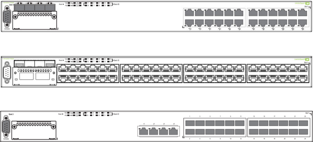
• The Brocade FCX 624S stackable switch has twenty 10/100/1000 Mbps ports plus four Combo ports, which include four
10/100/1000 Mbps RJ-45 ports and four 100/1000 Mbps SFP ports. The switch has two management interfaces, a DB-9
serial port (Console) on the front panel and an RJ-45 port (Out-of-band Management Interface) on the rear panel. Two rear-
panel power supply receptacles allow for up to two power supply units. Two dedicated 16 GbE CX4 ports on the rear panel
allow stacking for up to eight units. The front panel also has a module slot for an optional two-port 10 Gbps XFP module.
• The Brocade FCX 648S stackable switch has forty four 10/100/1000 Mbps RJ-45 ports plus four Combo ports, which
include four 10/100/1000 Mbps RJ-45 ports and four 100/1000 Mbps SFP ports. The switch has two management
interfaces, a DB-9 serial port (Console) on the front panel and an RJ-45 port (Out-of-band Management Interface) on the rear
panel. Two rear-panel power supply receptacles allow for up to two power supply units. Two dedicated 16 Gbps Ethernet CX4
ports on the rear panel allow stacking for up to eight units. The front panel also has a module slot for an optional two-port 10
Gbps Ethernet XFP module.
• The Brocade FCX 624S-F stackable switch has two management interfaces, a DB-9 serial port (Console) on the front panel
and an RJ-45 port (Out-of-band Management Interface) on the rear panel. Two rear-panel power supply receptacles allow for
up to two power supply units. Two dedicated 16 Gbps Ethernet CX4 ports on the rear panel allow stacking for up to eight units.
The front panel also has a module slot for an optional two-port 10 Gbps Ethernet XFP module.
• The Brocade FCX 624S-HPOE stackable switch has twenty 100/1000 Mbps ports plus four Combo ports, which include four
10/100/1000 Mbps RJ-45 ports and four 100/1000 Mbps SFP ports. The switch has two management interfaces, a DB-9
serial port (Console) on the front panel and an RJ-45 port (Out-of-band Management Interface) on the rear panel. Two rear-
panel power supply receptacles allow for up to two power supply units. Two dedicated 16 Gbps Ethernet CX4 ports on the rear
panel allow stacking for up to eight units. The front panel also has a module slot for an optional two-port 10 Gbps Ethernet XFP
module.
• The Brocade FCX 648S-HPOE has is a stackable switch with forty four 10/100/1000 Mbps ports plus four Combo ports,
which include four 10/100/1000 Mbps RJ-45 ports and four 100/1000 Mbps SFP ports. The switch has two management
interfaces, a DB-9 serial port (Console) on the front panel and an RJ-45 port (Out-of-band Management Interface) on the rear
panel. Two rear-panel power supply receptacles allow for up to two power supply units. Two dedicated 16 Gbps Ethernet CX4
ports on the rear panel allow stacking for up to eight units. The front panel also has a module slot for an optional two-port 10
Gbps Ethernet XFP module.
• The Brocade FCX 624-E switch has twenty four 10/100/1000 Mbps ports. The device has two management interfaces on
the front panel, a DB-9 serial port (Console) and an RJ-45 port (Out-of-band Management Interface). The front panel has a slot
for an optional four-port 1GbE SFP module (works as Combo port) or four-port 10 Gbps SFP+ module. On the rear panel a
removable fan tray provides a cooling airow from the front to the rear of the device. Two rear-panel power supply receptacles
accommodate up to two power supply units that also support a front-to-rear cooling airow.
• The Brocade FCX 624-I switch has twenty four 10/100/1000 Mbps ports. The device has two management interfaces on the
front panel, a serial port (Console) and an RJ-45 port (Out-of-band Management Interface). The front panel has a slot for an
optional four-port 1GbE SFP module (works as Combo port) or four-port 10 Gbps SFP+ module. On the rear panel a
removable fan tray provides a cooling airow from the rear to the front of the device. Two rear-panel power supply receptacles
accommodate up to two power supply units that also support a rear-to-front cooling airow.
Brocade FCX Series Hardware Installation Guide
Part Number: 53-1003616-03 13
• The Brocade FCX 648-E switch has forty four 10/100/1000 Mbps ports. The device has two management interfaces on the
front panel, a serial port (Console) and an RJ-45 port (Out-of-band Management Interface). The front panel has a slot for an
optional four-port 1GbE SFP module (works as Combo port) or four-port 10 Gbps SFP+ module. On the rear panel a
removable fan tray provides a cooling airow from the front to the rear of the device. Two rear-panel power supply receptacles
accommodate up to two power supply units that also support a front-to-rear cooling airow..
• The Brocade FCX 648-I switch has forty four 10/100/1000 Mbps ports. The device has two management interfaces on the
front panel, a serial port (Console) and an RJ-45 port (Out-of-band Management Interface). The front panel has a slot for an
optional four-port 1GbE SFP module, (works as Combo port) or four-port 10 Gbps SFP+ module. On the rear panel a
removable fan tray provides a cooling airow from the rear to the front of the device. Two rear-panel power supply receptacles
accommodate up to two power supply units that also support a rear-to-front cooling airow.
NOTE
All FCX models support Layer 2 and Enterprise Layer 3 protocols (RIP, OSPF, PIM). FCX models can be ordered from the
factory as -ADV (Advanded Layer 3) models, which adds support for the Layer 3 BGP routing protocol and GRE.
The following sections describe the physical characteristics of the FastIron CX models. For more details about physical dimensions,
power supply specications, and pinouts, refer to the "Brocade FCX Series Technical Specications" section.
The following gures show the front panels of the FastIron CX models. For more information about Combo ports, refer to Network
interfaces for Brocade FCX 624-E, FCX 624-I, FCX 648-E, and FCX 648-I on page 17. For more information about control features
in general, refer to Control features on page 16.
FIGURE 1 Brocade FCX 624S front panel
FIGURE 2 Brocade FCX 648S front panel
FIGURE 3 Brocade FCX 624S-F front panel
Hardware features
Brocade FCX Series Hardware Installation Guide
14 Part Number: 53-1003616-03
FIGURE 4 Brocade FCX 624S-HPOE front panel
FIGURE 5 Brocade FCX 648S-HPOE front panel
FIGURE 6 Brocade FCX 648S-HPOE rear panel
FIGURE 7 Brocade FCX 624-E front panel
FIGURE 8 Brocade FCX 624-I front panel
FIGURE 9 Brocade FCX 648-E front panel
Hardware features
Brocade FCX Series Hardware Installation Guide
Part Number: 53-1003616-03 15
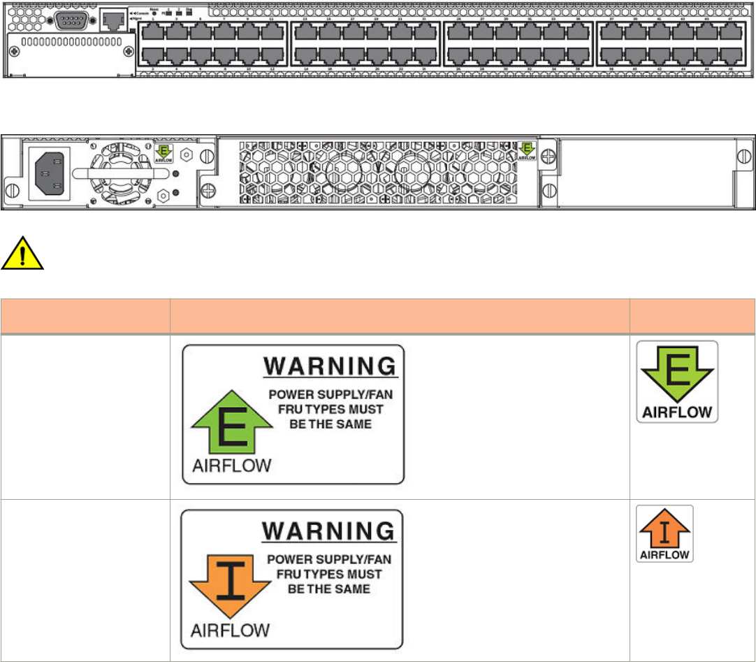
FIGURE 10 Brocade FCX 648-I front panel
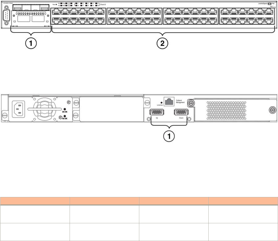
FIGURE 11 Brocade FCX 624-E, FCX 624-I, FCX 648-E, and FCX 648-I rear panels
CAUTION
Ensure that the airow direction of the power supply unit matches that of the installed fan tray. The power supplies and fan
trays are clearly labeled with either a green arrow with an "E", or an orange arrow with an "I."
Device Label on required power supply Label on required fan
tray
Brocade FCX 624-E and
Brocade FCX 648-E
Brocade FCX 624-I and
Brocade FCX 648-I
Control features
Each device front panel includes the following control features:
• Serial management interface (the DB-9 port labeled Console )
• Out-of-band RJ-45 management Interface
Hardware features
Brocade FCX Series Hardware Installation Guide
16 Part Number: 53-1003616-03
Serial management interface (DB-9 Console port)
The serial management interface allows you to congure and manage the device using a third-party terminal emulation application on a
directly-connected PC. A straight-through EIA or TIA DB-9 serial cable (M or F) ships with the device. The serial management interface
(the DB-9 Console port) is located in the left corner of the front panel.
Out-of-band RJ-45 management interface
The out-of-band RJ-45 management interface enables you to congure and manage the device using a third-party terminal emulation
application on a directly-connected PC.
Network interfaces for Brocade FCX 624S, FCX 648S, FCX 624S-F, FCX 624S-HPOE, and FCX
648S-HPOE
FCX devices contain the following interfaces:
• 10/100/1000 Mbps ports with RJ-45 copper connectors
• 100/1000 Mbps ports with mini-GBIC slots for SFP MSA-compliant ber transceivers
• Optional 2-port 10 Gbps Ethernet XFP module
• CX4 stacking ports
NOTE
Brocade recommends that you refer to Cable specications on page 65 before connecting a cable to any of the ports.
Network interfaces for Brocade FCX 624-E, FCX 624-I, FCX 648-E, and FCX 648-I
FastIron CX devices contain the following interfaces:
• 10/100/1000 ports with RJ-45 copper connectors
• 100/1000 ports with mini-GBIC slots for MSA-compliant SFP transceivers
• Optional 4-port 1 Gbps Ethernet SFP module
• Optional 4-port 10 Gbps Ethernet SFP+ module
NOTE
Brocade recommends that you refer to Cable specications on page 65 before connecting a cable to any of the ports.
FastIron CX 10/100/1000 BASE-T ports
All FastIron CX devices except for the ber models contain 24 or 48 RJ-45 ports that operate at 10 Mbps or 100 Mbps, half or full
duplex, or at 1000 Mbps, full duplex. FCX ber models contain 24 SFP ports. Because all ports support automatic MDI or MDI-X
operation, you can use straight-through cables for all network connections to PCs or servers, or to other switches or hubs. In addition, it is
ideal and preferred to use straight-through cable for switch-to-switch connections.
Each of these ports supports auto-negotiation, so the optimum transmission mode (half or full duplex), and the data rate (10, 100, or
1000 Mbps) can be selected automatically. If a device connected to one of these ports does not support auto-negotiation, the
communication mode of the port can be congured manually.
Combination ports
FCX devices contain four combination ports, which are four Small Form Factor Pluggable (SFP) network interfaces (1F–4F) that are
shared with four of the RJ-45 ports (ports 1–4). In the default conguration, if an SFP transceiver is installed in a slot and has a valid link
Hardware features
Brocade FCX Series Hardware Installation Guide
Part Number: 53-1003616-03 17
on its port, the associated RJ-45 port is disabled and cannot be used. The switch can also be congured to force the use of a
combination RJ-45 port or SFP slot, as required.
NOTE
Brocade FCX 624-E, FCX 624-I, FCX 648-E, and FCX 648-I devices do not ship with SFP ports. You must install the
optional SFP module for SFP support.
Slot locations
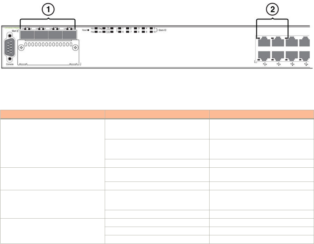
There are three slot locations on Brocade FCX Series devices: slots 3 and 1 on the front panel and slot 2 on the rear panel.
FIGURE 12 Slot locations on the front panel of Brocade FCX Series devices
1. Slot 3
2. Slot 1
FIGURE 13 Slot location on the rear panel of Brocade FCX Series devices
1. Slot 2 (default stacking ports)
Slot designations
The slot designations for FCX models are shown in the following table:
TABLE 1 Stack unit slots for FCX stackable devices
Device Slot 1 Slot 2 Slot 3
Brocade FCX 624S 20 10/100/1000 Mbps ports
plus 4 Combo ports (RJ-45 ports
1–4, or SFP ports 1F-4F)
2-port 16 Gbps CX4 stacking
module on rear panel
2-port 10 Gbps XFP module
Brocade FCX 648S 44 20 10/100/1000 Mbps ports
plus 4 Combo ports (RJ-45 ports
1–4, or SFP ports 1F–4F)
2-port 16 Gbps CX4 stacking
module on rear panel
2-port 10 Gbps XFP module
Hardware features
Brocade FCX Series Hardware Installation Guide
18 Part Number: 53-1003616-03

TABLE 1 Stack unit slots for FCX stackable devices (continued)
Device Slot 1 Slot 2 Slot 3
Brocade FCX 624S-F 20 100/1000 Mbps SFP ports
plus 4 Combo ports
10/100/1000 Mbps RJ-45 on
front panel
2-port 16 Gbps CX4 stacking
module on rear panel
2-port 10 Gbps XFP module
Brocade FCX 624-E and Brocade
FCX 624-I devices with optional 4-
port 1 Gbps SFP module
20 10/100/1000 Mbps RJ-45
ports, plus 4-port 1 Gbps SFP
module (optional module)
combined with the rst four
10/100/1000 Mbps RJ-45
copper ports (acting as a Combo
port)
N/A N/A
Brocade FCX 648-E and Brocade
FCX 648-I devices with optional 4-
port 1 Gbps SFP module
44 10/100/1000 Mbps RJ-45
ports, plus 4-port 1 Gbps SFP
module (optional) combined with
the rst four 10/100/1000 Mbps
RJ-45 copper ports (acting as a
Combo port).
N/A N/A
Brocade FCX 624-E and Brocade
FCX 624-I devices with optional 4-
port 10 Gbps SFP+ module
24 10/100/1000 Mbps RJ-45
ports
4-port 10 Gbps SFP+ module on
front panel
(optional module)
N/A
Brocade FCX 648-E and Brocade
FCX 648-I devices with optional
4r-port 10 Gbps SFP+ module
48 10/100/1000 Mbps RJ-45
ports
4-port 10 Gbps SFP+ module on
front panel
(optional module)
N/A
SFP interfaces
This section describes the network interfaces supported on FCX devices. For information about supported SFP and SFP+ transceivers,
refer to the product data sheet.
TABLE 2 SFP network interfaces
Interface Show Media Description
1000Base-BX-D M-GBXD
1000Base-BX-U M-GBXU
1000Base-LHA M-LHA
1000Base-LHB M-LHB
1000Base-LX M-LX
1000Base-LH M-LH
1000Base-SX M-SX
1000Base-T C
100Base-T C**
10Base-T C**
100Base-FX M-FX
Optional two-port 10 Gbps XFP uplink module
The Brocade FCX 624S, FCX 648S, FCX 624S-F, FCX 624S-HPOE, and FCX 648S-HPOE devices include a slot on the front panel
for a two-port 10 Gbps XFP uplink module. This module operates at 10 Gbps full duplex.
Hardware features
Brocade FCX Series Hardware Installation Guide
Part Number: 53-1003616-03 19
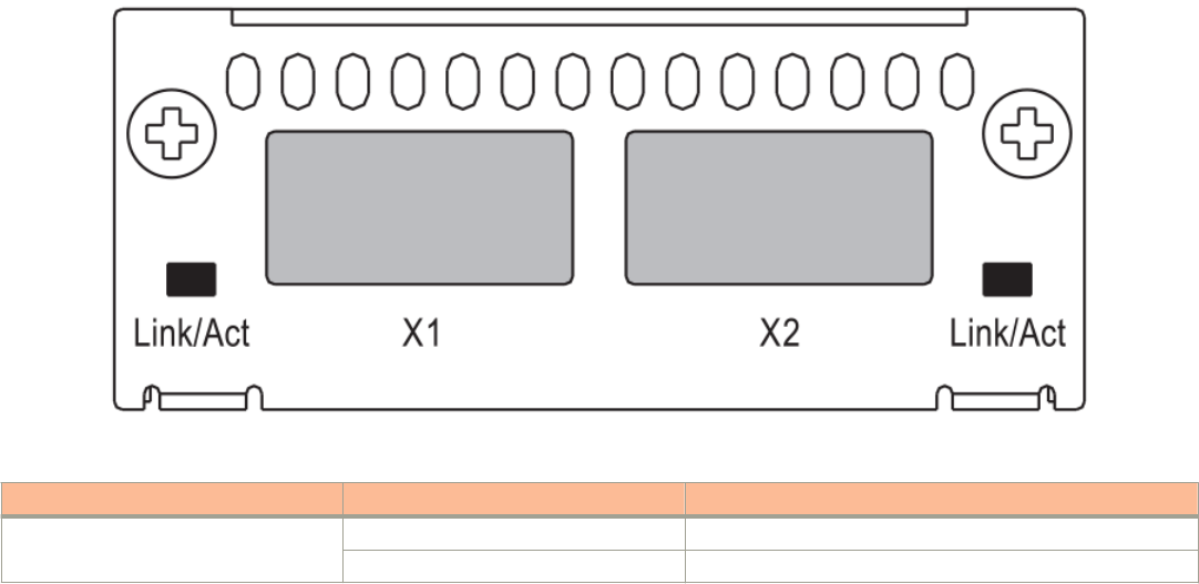
NOTE
The 10 Gbps XFP module is not hot-swappable.
FIGURE 14 Two-port 10 Gbps XFP module
TABLE 3 Two-port 10 Gbps XFP module port status LEDs
LED Condition Status
Link or Act LED (Link or Activity) On or ashing Green Port has a valid link at 10 Gbps. Flashing indicates activity.
O The link is down.
Optional 4x1G SFP+ and 4x10G SFP+ modules
The Brocade FCX 624-E, FCX 624-I, FCX 648-E, and FCX 648-I devices include a slot on the front panel for a four-port 1 Gbps SFP
module, or a four-port 10 Gbps SFP+ module. The 1 Gbps SFP module operates at 1 Gbps full duplex, and the 10 Gbps SFP+ module
operates at 10 Gbps full duplex.
FCX-I and FCX-E devices can be used in a homogeneous stack by installing the optional 4-port 10 Gbps SFP+ module, and connecting
devices using standard duplex LC cables. These devices cannot be combined in a stack with non-FCX devices. For detailed information
about how to congure FCX devices in a homogeneous stack, refer to the FastIron Ethernet Switch Stacking Conguration Guide.
NOTE
The 1 Gbps SFP and 10 Gbps SFP+ modules are not hot-swappable.
Hardware features
Brocade FCX Series Hardware Installation Guide
20 Part Number: 53-1003616-03
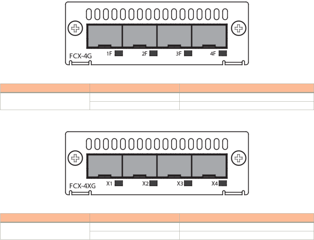
FIGURE 15 Four-port 1 Gbps SFP module
TABLE 4 Four-port 1 Gbps SFP module status LEDs
LED Condition Status
Link or Act LED (Link or Activity) On or ashing Green Port has a valid link at 1 Gbps. Flashing indicates activity.
O The link is down.
FIGURE 16 Four-port 10 Gbps SFP+ module
TABLE 5 Four-port 10 Gbps SFP+ module status LEDs
LED Condition Status
Link or Act LED (Link or Activity) On or ashing Green Port has a valid link at 10 Gbps. Flashing indicates activity.
O The link is down.
NOTE
The two left ports on the SFP+ module do not pass regular Ethernet trac by default. The stack disable CLI command must
be congured on these two ports in order for them to pass regular trac.
16/10 Gbps Ethernet CX4 stacking module
The Brocade FCX 624S, FCX 648S, FCX 624S-F, FCX 624S-HPOE, and FCX 648S-HPOE devices include two 16/10 Gbps
Ethernet CX4 ports on the rear panel (the stacking ports). The device can perform data transmission directly through copper links of up to
3 meters.
The Up Link and Down Link LEDs on the front panel indicate operational status. If the Up Link or Down Link LED is on, the port is
connected. If the Up Link or Down Link LED is o, no connection exists, or the link is down.
Hardware features
Brocade FCX Series Hardware Installation Guide
Part Number: 53-1003616-03 21
Cable specications for CX4 stacking ports
The following cable specications apply to the CX4 stacking ports:
• Support for 802.3ak or 10 Gbps Ethernet CX4 standard and 16 Gbps inter-unit stacking (up to 8 units in a stack)
• Support for cables up to 3 meters in length
• Requires latch-style receptacle or SFF-8470 plug
NOTE
Brocade FCX 624-E, FCX 624-I, FCX 648-E, and FCX 648-I devices can be added to a stack using the rst two ports on a
four-port 10 Gbps SFP+ module (optional) using standard duplex LC cables.
Optional 2-port 10 Gbps SFP+ uplink module
Feature description for the 2-port 10 Gbps SFP+ module including modied CLI examples
The following Brocade FCX devices include a slot on the front panel for a two-port 10 Gbps SPF+ uplink module. This module operates
at 10 Gbps full duplex.
• Brocade FCX 624S
• Brocade FCX 648S
• Brocade FCX 624S-F
• Brocade FCX 624S-HPOE
• Brocade FCX 648S-HPOE
The 2-port 10 Gbps SPF+ uplink module can replace the 2-port XFP module in the xed slot 3. Port mapping is the same as for the
2x10 XFP with slot 3 and port 1 or 2, for example, 1/3/1 and 1/3/2. Stacking is supported using the stack default-port command with
the 1/3/1 and 1/3/2 options.
The module is named FCX-2SFPP 2-port 10G Module (2-SFP+) in conguration and output.
Follow these steps to replace the 2x10 SFP+ module:
1. Remove any xed LAG conguration.
2. Power down only the member switch in the stack because the 2x10 SFP+ module is not hot-swappable. However, the links in
the old 2x10 SFP+ module will be in up state for a short duration.
3. Insert the new 2x10 SFP+ module.
4. Power on the member switch in the stack.
5. In active/standby, reload the complete stack.
NOTE
There should not be any trac injection until you reload the stack and the links are up
again.
6. Recongure the xed LAGs.
Hardware features
Brocade FCX Series Hardware Installation Guide
22 Part Number: 53-1003616-03
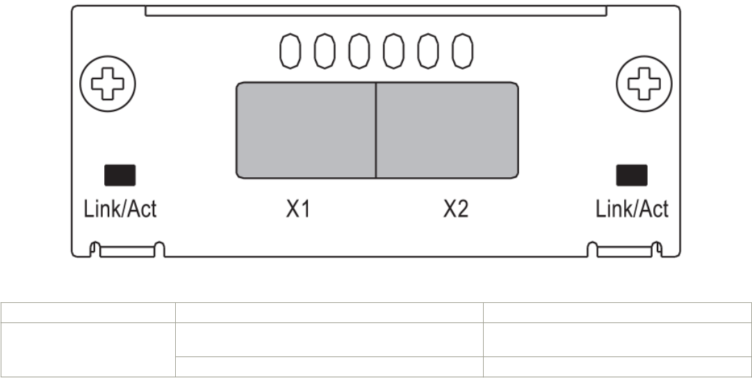
FIGURE 17 Two-port 10 Gbps SFP+ module
TABLE 6 10 Gbps SFP+ module port status LEDs
LED Condition Status
Link or Act LED (Link or Activity) On or ashing green Port has a valid link at 10 Gbps. Flashing indicates
activity.
O The port is down.
Hardware features
Brocade FCX Series Hardware Installation Guide
Part Number: 53-1003616-03 23
Modied CLI examples for the 2-port 10 Gbps SFP+ module
The following sample output from the show module command displays an entry for the 2-port 10 Gbps SFP+ module.
device# show module
Module Status Ports Starting MAC
U1:M1 FCX-48GS POE 48-port Management Module OK 48 0024.38c9.4d00
U1:M2 FCX-2XGC 2-port 16G Module (2-CX4) OK 2 0024.38c9.4d31
U1:M3 FCX-2SFPP 2-port 10G Module (2-SFP+) OK 2 0024.38c9.4d33
The following sample output from the show version command shows that the 2-port 10 Gbps SFP+ module is in slot 3.
device# show version
Copyright (c) 1996-2011 Brocade Communications Systems, Inc.
UNIT 1: compiled on Oct 18 2012 at 16:01:04 labeled as FCXS07300b1
(5373912 bytes) from Primary FCXS07300b1.bin
SW: Version 07.3.00b1T7f1
Boot-Monitor Image size = 370663, Version:07.3.00T7f5 (grz07300b1)
HW: Stackable FCX648S-HPOE-PREM (PROM-TYPE FCX-ADV-U)
==========================================================================
UNIT 1: SL 1: FCX-48GS POE 48-port Management Module
Serial #: BCYXXXXXXXX
License: BASE_SOFT_PACKAGE (LID: deaHHJIhFNb)
P-ENGINE 0: type DB90, rev 01
P-ENGINE 1: type DB90, rev 01
PROM-TYPE: FCX-ADV-U
==========================================================================
UNIT 1: SL 2: FCX-2XGC 2-port 16G Module (2-CX4)
==========================================================================
UNIT 1: SL 3: FCX-2SFPP 2-port 10G Module (2-SFP+)
==========================================================================
800 MHz Power PC processor 8544E (version 0021/0022) 400 MHz bus
65536 KB flash memory
256 MB DRAM
STACKID 1 system uptime is 2 days 10 minutes 24 seconds
The system : started=warm start reloaded=by "reload"
The following is sample output of the show running-cong command.
device# show running-config
!
Startup-config data location is flash memory
!
Startup configuration:
!
ver 07.3.00a001T7f1
!
stack unit 1
module 1 fcx-48-poe-port-management-module
module 2 fcx-cx4-2-port-16g-module
module 3 fcx-sfpp-2-port-10g-module
!
The following is sample output of the show media and show optic commands with some conguration.
device# show media
1/1/1:C 1/1/2:C 1/1/3:C 1/1/4:C 1/1/5:C 1/1/6:C 1/1/7:C 1/1/8:C
1/1/9:C 1/1/10:C 1/1/11:C 1/1/12:C 1/1/13:C 1/1/14:C 1/1/15:C 1/1/16:C
1/1/17:C 1/1/18:C 1/1/19:C 1/1/20:C 1/1/21:C 1/1/22:C 1/1/23:C 1/1/24:C
1/1/25:C 1/1/26:C 1/1/27:C 1/1/28:C 1/1/29:C 1/1/30:C 1/1/31:C 1/1/32:C
1/1/33:C 1/1/34:C 1/1/35:C 1/1/36:C 1/1/37:C 1/1/38:C 1/1/39:C 1/1/40:C
1/1/41:C 1/1/42:C 1/1/43:C 1/1/44:C 1/1/45:C 1/1/46:C 1/1/47:C 1/1/48:C
1/2/1:XG-CX4 1/2/2:XG-CX4
1/3/1:XG-SR 1/3/2:XG-SR
device# show media e 1/3/1
Port 1/3/1: Type : 10G XG-SR(SFP +)
Vendor: Brocade Version: 1
Part# : PLRXPLSCS4371 Serial#: CXXXXXXXX
device(config)# op 1
Enable optical monitoring and set alarm/warn interval to 1 minute(s)
Hardware features
Brocade FCX Series Hardware Installation Guide
24 Part Number: 53-1003616-03
device(config)# show optic 1/3/1
Port Temperature Tx Power Rx Power Tx Bias Current
+----+-----------+--------------+--------------+---------------+
1/3/1 32.7421 C -002.3195 dBm -002.5947 dBm 6.212 mA
Normal Normal Normal Normal
device# show media e 1/3/1
Port 1/3/1: Type : 10G XG-ER(SFP +)
Vendor: BROCADE Version: A
Part# : 57-0000085-01 Serial#: XXXXXXXXXXXXXXX
device# show media e 1/3/2
Port 1/3/2: Type : 10G XG-USR (SFP +)
Vendor: BROCADE Version: A
Part# : 57-1000130-01 Serial#: XXXXXXXXXXXXXXX
device# show media
1/1/1:C 1/1/2:C 1/1/3:C 1/1/4:C 1/1/5:C 1/1/6:C 1/1/7:C 1/1/8:C
1/1/9:C 1/1/10:C 1/1/11:C 1/1/12:C 1/1/13:C 1/1/14:C 1/1/15:C 1/1/16:C
1/1/17:C 1/1/18:C 1/1/19:C 1/1/20:C 1/1/21:C 1/1/22:C 1/1/23:C 1/1/24:C
1/1/25:C 1/1/26:C 1/1/27:C 1/1/28:C 1/1/29:C 1/1/30:C 1/1/31:C 1/1/32:C
1/1/33:C 1/1/34:C 1/1/35:C 1/1/36:C 1/1/37:C 1/1/38:C 1/1/39:C 1/1/40:C
1/1/41:C 1/1/42:C 1/1/43:C 1/1/44:C 1/1/45:C 1/1/46:C 1/1/47:C 1/1/48:C
1/2/1:XG-CX4 1/2/2:XG-CX4
1/3/1:XG-ER 1/3/2:XG-USR
Specifying a port address
You can specify a port address for a data port, stacking port, or a management port.
Specifying a data port
The port address format is stack unit/slot/port, where:
•stack unit--Species the stack unit ID. Range is from 1 to 8. If the device is not part of a stack, the stack unit ID is 1.
•slot--Species the slot number. Can be 1 or 3.
•port--Species the port number in the slot. Range is from 1 to 24 (24-port models) or 1 to 48 (48-port models).
This example indicates it is stack unit 1:
Brocade(config)# interface ethernet 1/1/2
Specifying a stacking port
The port address format is stack unit/slot/port, where:
•stack unit--Species the stack unit ID. Range is from 1 to 8.
•slot--Species the slot number. Default stacking ports are in slot 2 (FCX S/S-F).
•port--Species the port number in the slot. Default stacking ports in slot 2 are ports 1 and 2.
This example shows how to specify port 2 in slot 2 of unit 3 in a stack:
Brocade(config)# interface ethernet 3/2/2
Specifying a management port
The management port number is always 1. This example shows how to specify the management port:
Brocade(config)# interface management 1
Hardware features
Brocade FCX Series Hardware Installation Guide
Part Number: 53-1003616-03 25
–Port, system, and power status LEDs for Brocade FCX 624S, FCX 648S, FCX 624S-F, FCX
624S-HPOE, and FCX 648S-HPOE
FCX switches include a display panel for key system and port indicators that simplies installation and network troubleshooting. The
LEDs are located on the front panel for easy viewing.
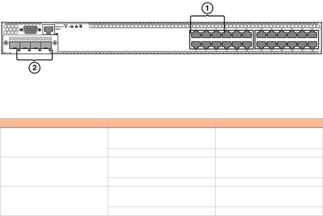
FIGURE 18 Port status LEDs
1. Port status LEDs
2. Port status LEDs
TABLE 7 Port status LEDs
LED Condition Status
Ethernet(1–24/48)
Link or Activity or Speed
On/Flashing Green The port has established a valid link at 1000
Mbps. Flashing indicates the port is transmitting
and receiving user packets.
On/Flashing Amber The port has established a valid link at 10 or
100 Mbps. Flashing indicates the port is
transmitting and receiving user packets.
O A link is not established with a remote port.
HPOE(1–24/48) On Green The port is providing HPOE power to a
connected device.
O The port is not providing HPOE power.
SFP(1F–4F)
Link or Activity
On/Flashing Green The SFP port has established a valid link.
Flashing indicates the port is transmitting and
receiving user packets.
O A link is not established with a remote port.
SFP(1F–4F)
Speed
On Green The SFP port is operating at 1000 Mbps.
On Amber The SFP port is operating at 100 Mbps.
O A link is not established with a remote port.
Hardware features
Brocade FCX Series Hardware Installation Guide
26 Part Number: 53-1003616-03
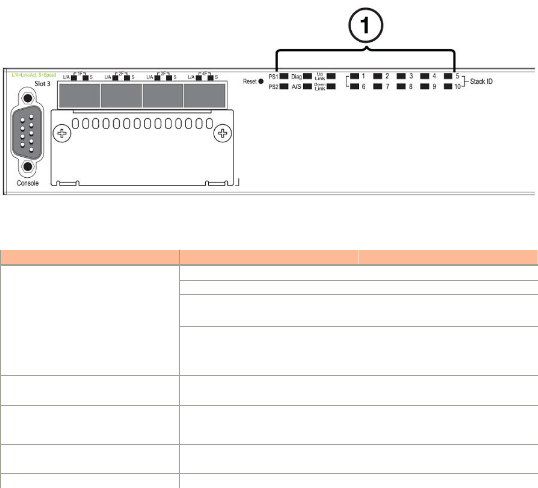
FIGURE 19 System status LEDs
1. System status LEDs
TABLE 8 System status LEDs
LED Condition Status
PS1
PS2
(Power Supply Status)
Green Power supply is operating normally.
Amber Power supply fault.
O Power o or failure.
Diag
(Diagnostic)
Flashing Green System self-diagnostic test in progress.
Green System self-diagnostic test successfully
completed.
Amber System self-diagnostic test has detected a fault.
(Blower, thermal or any interface fault.)
A or S
(Active or Standby)
Green The device is the Active controller. If this LED is
ashing green, the system is initializing.
Amber Indicates the device is the Standby controller.
O Device is operating as a stack member, or is in
standalone mode.
Up Link or Down Link (Stacking uplink or
downlink port status)
Green Uplink is operating normally.
O Uplink has failed or there is no link.
Stack ID (1-8) Green Indicates the device stack ID.
Hardware features
Brocade FCX Series Hardware Installation Guide
Part Number: 53-1003616-03 27
FIGURE 20 Power status LEDs
1. Power status LEDs
TABLE 9 Power status LEDs
LED Condition Status
DC OK Green DC output ok
Red DC output fail
AC OK Green AC input ok
O AC input fail
NOTE
Both "AC OK" and "DC OK" LEDs must be green for the device to function normally.
TABLE 10 Switch status for two installed power supply units
State LED PSU1 PSU2 Switch Status Load Sharing HPOE Budget
(HPOE models
only)
Four Green PSU
LEDs
AC OK Green Green Running Yes 820W
DC OK Green Green
Single Red ‘DC
OK’ LED
AC OK Green Green Running No 410W
DC OK Green Red
Both ‘DC OK’
LEDs Red
AC OK Green Green Failure No None
DC OK Red Red
One PSU with both
‘AC OK’ ‘DC OK’
LEDs O
AC OK Green O Running No 410W
DC OK Green O
‘DC OK’ LEDs Red
and O
AC OK Green O Failure No None
DC OK Red O
All ‘AC OK’ LEDs
O
AC OK O O Power O or
Failure
No None
DC OK O O
Hardware features
Brocade FCX Series Hardware Installation Guide
28 Part Number: 53-1003616-03
NOTE
When two 620W power supplies are installed in an HPOE system that has no load or light load on the POE function, one of
two power supplies may have its "DC OK" LED light red. There is no fault in the power supply or the system and the switch is
functioning normally. The LED will turn to green automatically once the load is increased over the minimum load requirement.
In congurations with a single power supply installed the "DC OK" LED will light green in a no-load or light-load condition.
Port, system, and power status LEDs for Brocade FCX 624-E, FCX 624-I, FCX 648-E, and FCX
648-I
FCX switches include a display panel for key system and port indicators that simplies installation and network troubleshooting. The
LEDs are located on the front panel for easy viewing.
FIGURE 21 Port status LEDs
1. Port status LEDs
2. SFP or SFP+ port status LEDs
TABLE 11 Port status LEDs
LED Condition Status
Ethernet(1–24/48)
Link or Activity or Speed
On/Flashing Green The port has established a valid link at
10/100/1000 Mbps. Flashing indicates the
port is transmitting and receiving user packets.
O A link is not established with a remote port.
SFP(1F–4F)
Link or Activity
On/Flashing Green The SFP port has established a valid 100/1000
Mbps link. Flashing indicates the port is
transmitting and receiving user packets.
O A link is not established with a remote port.
SFP+(1F–4F)
Link or Activity
On/Flashing Green The SFP+ port has established a valid 10 Gbps
link. Flashing indicates the port is transmitting
and receiving user packets.
O A link is not established with a remote port.
Hardware features
Brocade FCX Series Hardware Installation Guide
Part Number: 53-1003616-03 29
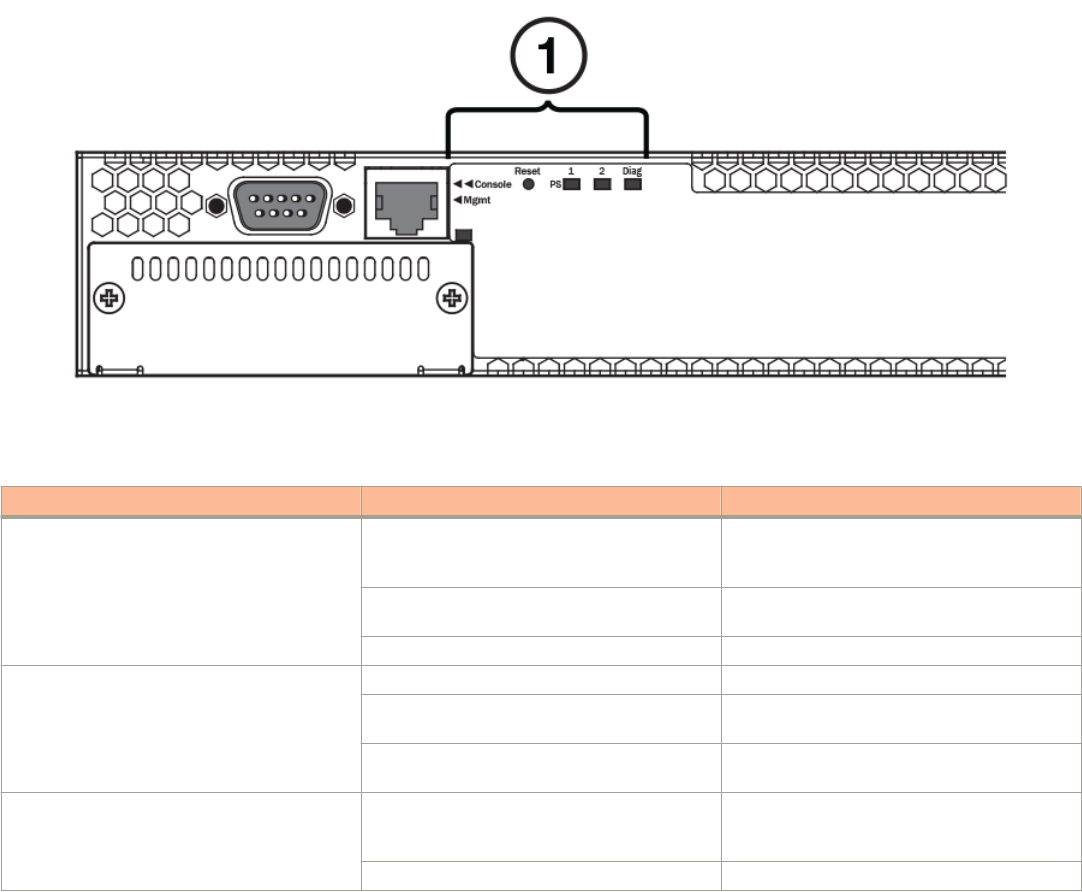
FIGURE 22 System status LEDs
1. System status LEDs
TABLE 12 System status LEDs
LED Condition Status
PS1
PS2
(Power Supply Status)
Green Power supply is operating normally. It is installed
properly and the power cord is attached to a
power source.
Amber Power supply fault. The power supply may not
be installed properly.
O Power o or failure.
Diag
(Diagnostic)
Flashing Green System self-diagnostic test in progress.
Green System self-diagnostic test successfully
completed.
Amber System self-diagnostic test has detected a fault.
(Blower, thermal or any interface fault.)
Out-of-band ManagementLink or Activity On/Flashing Green The port has established a valid link at
10/100/1000 Mbps. Flashing indicates the
port is transmitting and receiving user packets.
O A link is not established with a remote port.
Hardware features
Brocade FCX Series Hardware Installation Guide
30 Part Number: 53-1003616-03
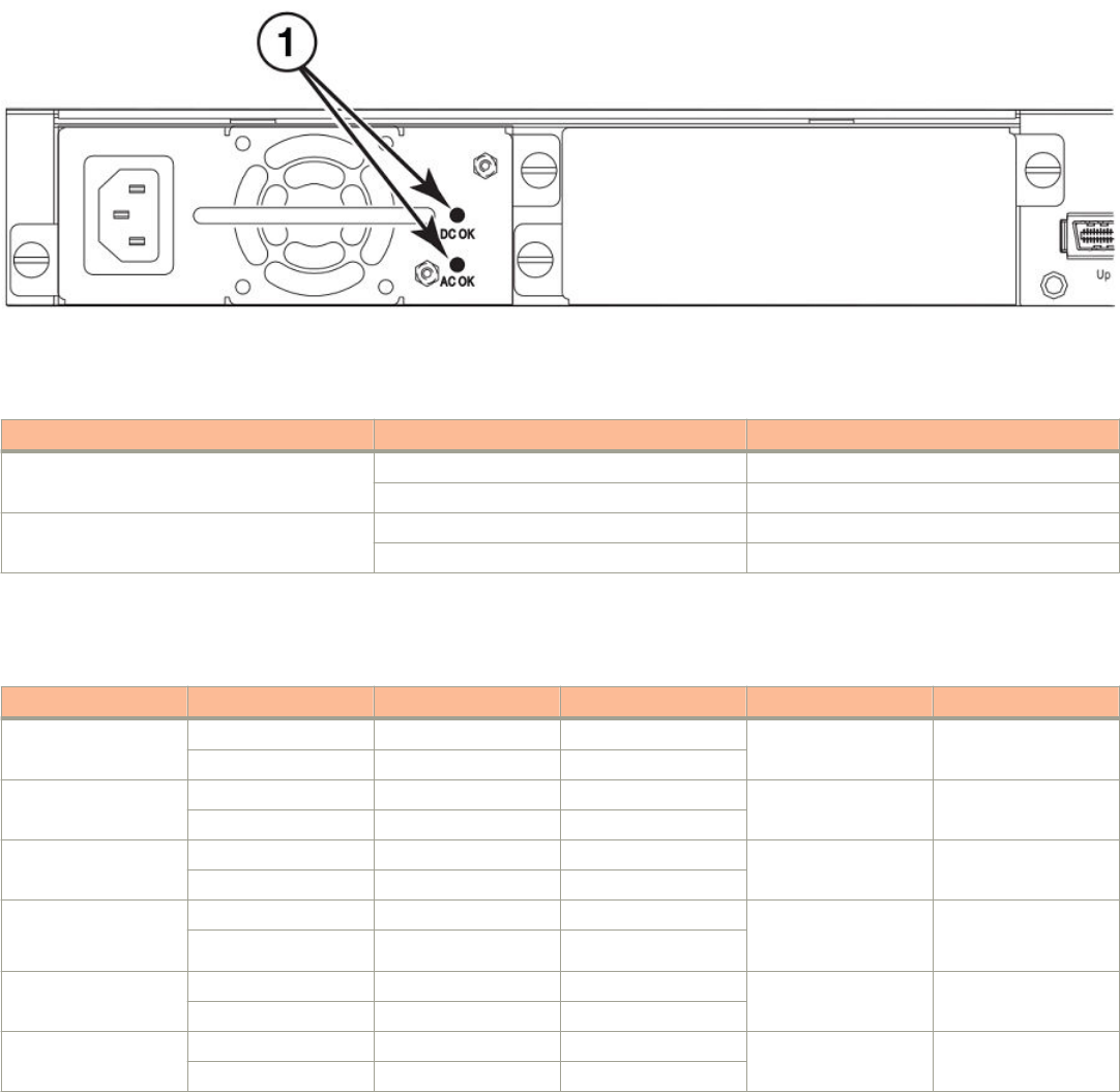
FIGURE 23 Power status LEDs
1. Power status LEDs
TABLE 13 Power status LEDs
LED Condition Status
DC OK Green DC output ok
Red DC output fail
AC OK Green AC input ok
O AC input fail
NOTE
Both "AC OK" and "DC OK" LEDs must be green for the device to function normally.
TABLE 14 Switch status for two installed power supply units
State LED PSU1 PSU2 Switch Status Redundancy
Four Green PSU LEDs AC OK Green Green Running Yes
DC OK Green Green
Single Red ‘DC OK’
LED
AC OK Green Green Running No
DC OK Green Red
Both ‘DC OK’ LEDs
Red
AC OK Green Green Failure No
DC OK Red Red
One PSU with both
‘AC OK’ ‘DC OK’ LEDs
O
AC OK Green O Running No
DC OK Green O
‘DC OK’ LEDs Red
and O
AC OK Green O Failure No
DC OK Red O
All ‘AC OK’ LEDs O AC OK O O Power O or Failure No
DC OK O O
Power supplies
The device has two power receptacles on the rear panel. Each device ships with one power supply installed. Brocade FCX 624S, FCX
648S, FCX 624S-F, FCX 624-E, FCX 624-I, FCX 648-E and FCX 648-I devices use a 210W PSU. Brocade FCX 624S-HPOE and
Brocade FCX 648S-HPOE devices use a 620W PSU.
Hardware features
Brocade FCX Series Hardware Installation Guide
Part Number: 53-1003616-03 31
Each power supply has one standard power receptacle for the AC power cable, and AC and DC status LEDs for easy monitoring and
troubleshooting.
A secondary power supply can be installed to provide backup power in case of a failure and for load-balancing when both power suppies
are operational.Load-balancing gives the power supplies a longer life span. Both 210W and 620W PSUs are hot-swappable.
For instructions on installing and replacing a power supply refer to Installing and replacing a power supply unit on page 50.
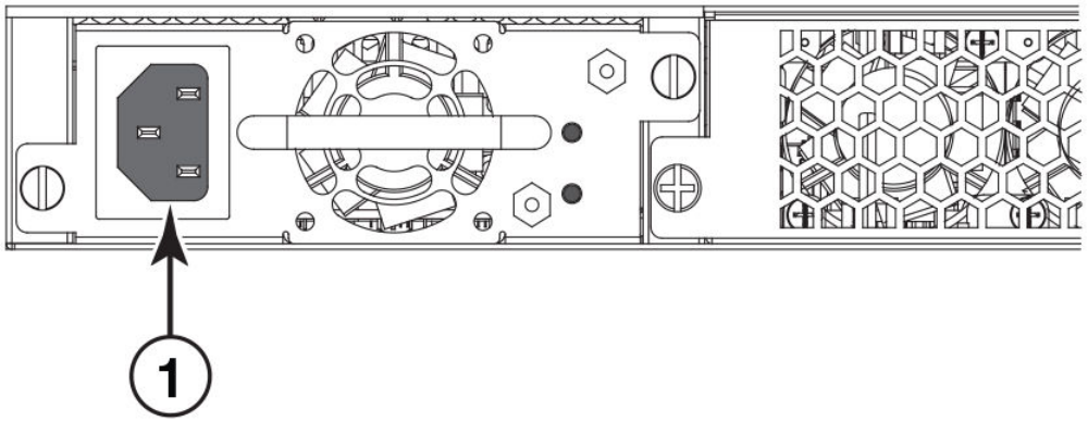
FIGURE 24 Brocade FCX 624-E, FCX 624-I, FCX 648-E, and FCX 648-I AC power supply receptacle
1. AC power receptacle
Power supply unit operation
When only one PSU is installed, both "AC OK" and "DC OK" LEDs on the installed PSU must be green for the FCX device to function
normally.
When two PSUs are installed, both "AC OK" and "DC OK" LEDs for one of the installed PSUs must be green for the FCX device to
function normally.
HPOE and HPOE + power supplies
Brocade FCX 624S-HPOE and Brocade FCX 648S-HPOE devices use a 620W PSU. When one PSU is powering the switch, the
HPOE budget is 410W. If both PSUs are installed and powering the switch, each PSU provides 410W to the switch, increasing the
HPOE budget to 820W.
Hardware features
Brocade FCX Series Hardware Installation Guide
32 Part Number: 53-1003616-03

Installing the FCX Switch
• Unpacking the device.......................................................................................................................................................................................33
• Installation tasks................................................................................................................................................................................................. 34
• Installation precautions....................................................................................................................................................................................34
• Preparing the installation site........................................................................................................................................................................35
• Connecting devices in a traditional stack.................................................................................................................................................41
• Powering on the system................................................................................................................................................................................. 47
• Attaching a PC or terminal.............................................................................................................................................................................48
• Installing and replacing a power supply unit...........................................................................................................................................50
• Installing or replacing fan trays.....................................................................................................................................................................50
• Installing an optional module .......................................................................................................................................................................52
DANGER
The procedures in this manual are for qualied service personnel.
DANGER
Before beginning the installation, see the precautions in “Power precautions.”
Unpacking the device
FCX devices ship with all of the items listed in the Package Contents section. Verify the contents of your shipping container. If any items
are missing, contact the place of purchase.
Package contents
The following items are included in your shipping carton:
• FCX device
• 115V AC power cable (for AC sourced devices)
• FCX-S and FCX-F devices ship with a .5M CX-4 stacking cable
• Rack mount brackets
• Warranty card
• A straight-through EIA or TIA DB-9 serial cable (F/F). The serial cable can be ordered separately from Brocade Communication
Systems, Inc. If you prefer to build your own cable, see the pinout information in Attaching a PC or terminal on page 48.
General requirements
To manage the system, you need a management station, such as a PC running a terminal emulation application. Connect the
management station to the Console serial port on the switch.
Use the serial connection to perform basic conguration tasks, including assigning an IP address and network mask to the system. This
information is required to manage the system using the Brocade Network Advisor or using the CLI through Telnet.
Brocade FCX Series Hardware Installation Guide
Part Number: 53-1003616-03 33
Installation tasks
Follow the steps listed in this section to install your device. Details for each of these steps are provided on the pages indicated.
TABLE 15 Installation tasks
Task Number Task Where to Find More Information
1 Ensure that the physical environment that will
host the device has the proper cabling and
ventilation.
Preparing the installation site on page 35
2 Install any required optional modules into the
switch.
Installing an optional module on page 52
3 Install the Brocade device on a desktop, in an
equipment rack.
Installing the device on page 36
4 Once the device is physically installed, plug the
device into a nearby power source that adheres
to the regulatory requirements outlined in this
manual.
Powering on the system on page 47
5 Attach a terminal or PC to the Brocade device.
This will enable you to congure the device
through the Command Line Interface (CLI).
Attaching a PC or terminal on page 48
6 No default password is assigned to the CLI. For
additional access security, assign a password.
Assigning permanent passwords on page 59
7 Before attaching equipment to the device, you
need to congure an interface IP address to the
subnet on which it will be located. Initial IP
address conguration is performed using the
CLI with a direct serial connection.
Conguring IP addresses on page 60
8 Once you power on the device and assign IP
addresses, the system is ready to accept
network equipment.
Installing the device on page 36
9 Test IP connectivity to other devices by pinging
them and tracing routes.
Testing connectivity on page 72
10 Continue conguring the device using the CLI.
You can also use Brocade Network Advisor to
manage the device.
Brocade Network Advisor User Manual
11 Secure access to the device. FastIron Ethernet Swich Secuity Guide
Installation precautions
Follow all precautions when installing a Brocade device.
General precautions
DANGER
All ber-optic interfaces use Class 1 lasers.
CAUTION
Do not install the device in an environment where the operating ambient temperature might exceed 40°C (104°F).
Installation tasks
Brocade FCX Series Hardware Installation Guide
34 Part Number: 53-1003616-03

CAUTION
Make sure the airow around the front, sides, and back of the device is not
restricted.
CAUTION
Never leave tools inside the chassis.
Lifting precautions
DANGER
Make sure the rack housing the device is adequately secured to prevent it from becoming unstable or falling over.
Power precautions
CAUTION
Use a separate branch circuit for each power cord, which provides redundancy in case one of the circuits fails.
DANGER
To avoid high voltage shock, do not open the device while the power is on.
CAUTION
Ensure that the device does not overload the power circuits, wiring, and over-current protection. To determine the
possibility of overloading the supply circuits, add the ampere (amp) ratings of all devices installed on the same circuit as the
device. Compare this total with the rating limit for the circuit. The maximum ampere ratings are usually printed on the
devices near the input power connectors.
DANGER
Disconnect the power cord from all power sources to completely remove power from the device.
CAUTION
Before plugging a cable into to any port, be sure to discharge the voltage stored on the cable by touching the electrical
contacts to ground surface.
DANGER
If the installation requires a dierent power cord than the one supplied with the device, make sure you use a power cord
displaying the mark of the safety agency that denes the regulations for power cords in your country. The mark is your
assurance that the power cord can be used safely with the device.
Preparing the installation site
Cabling infrastructure
Ensure that the proper cabling is installed at the site. Refer to Cable specications on page 66 or www.brocade.com for a summary of
supported cabling types and their specications.
Preparing the installation site
Brocade FCX Series Hardware Installation Guide
Part Number: 53-1003616-03 35

Installation location
Before installing the device, plan its location and orientation relative to other devices and equipment. Switches can be mounted in a
standard 19-inch equipment rack that meets EIA-310D standards, or on a at surface. Be sure to follow the guidelines below when
choosing a location.
The site should meet the following requirements:
• Maintain temperatures within 0 to 40°C (32 to 104° F) and humidity levels within 5% to 95%, non-condensing.
• Allow a minimum of 3 in. of space between the sides and the back of the device and walls or other obstructions for proper air
ow.
• Allow at least 3 in. of space at the front and back of the device for the twisted-pair, ber-optic, and power cabling.
• Be accessible for installing, cabling and maintaining the devices.
• Allow the status LEDs to be clearly visible.
• Allow for twisted-pair cable to be always routed away from power lines, uorescent lighting xtures and other sources of
electrical interference, such as radios and transmitters.
• Allow for the unit to be connected to a separate grounded power outlet that provides 110 to 240 VAC, 50 to 60 Hz, is within 2
m (6.6 feet) of each device and is powered from an independent circuit breaker. As with any equipment, a lter or surge
suppressor is recommended.
Installing the device
You can install Brocade devices on a desktop or in an equipment rack.
DANGER
Make sure the rack housing the device is adequately secured to prevent it from becoming unstable or falling over.
Preparing the installation site
Brocade FCX Series Hardware Installation Guide
36 Part Number: 53-1003616-03
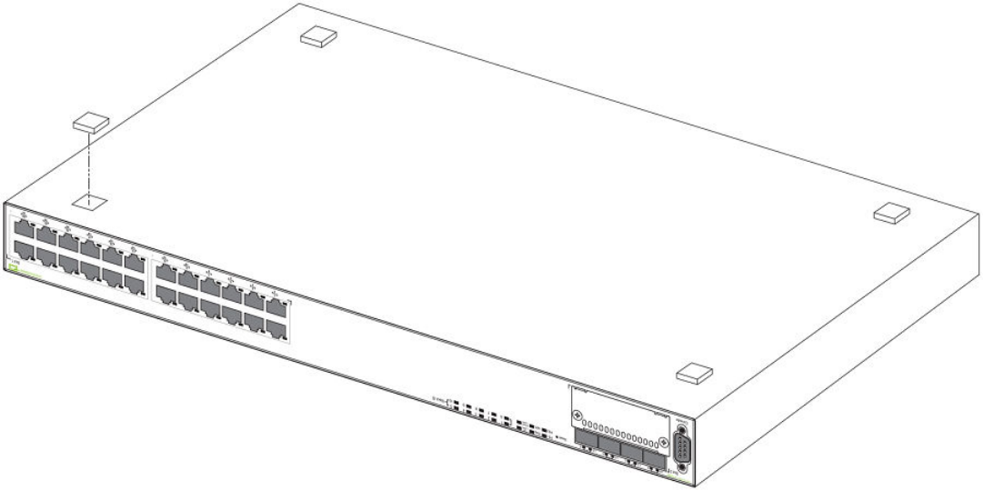
Desktop installation
FIGURE 25 Attaching the adhesive feet
1. Attach the four adhesive feet to the bottom of the rst switch.
2. Set the device on a at desktop, table, or shelf near an AC power source. Make sure that adequate ventilation is provided for the
system. A 3 inch clearance is recommended on each side.
3. If installing a single switch only, refer to Powering on the system on page 47.
4. If installing multiple switches, attach the adhesive feet to each one. Place each device squarely on top of the one below, in any
order.
Rack mount installation
NOTE
You need a #2 Phillips screwdriver for installation.
Before mounting the switch in a rack, pay particular attention to the following factors:
• Temperature: Because the temperature within a rack assembly may be higher than the ambient room temperature, check that
the rack-environment temperature is within the specied operating temperature range.
• Mechanical loading: Do not place any equipment on top of a rack-mounted unit.
• Circuit overloading: Be sure that the supply circuit to the rack assembly is not overloaded.
• Grounding: Rack-mounted equipment should be properly grounded. Particular attention should be given to supply connections
other than direct connections to the mains.
Preparing the installation site
Brocade FCX Series Hardware Installation Guide
Part Number: 53-1003616-03 37
Use the following steps to mount devices in rack.
1. Remove the rack mount kit from the shipping carton. The kit contains two L-shaped mounting brackets and mounting screws.
Preparing the installation site
Brocade FCX Series Hardware Installation Guide
38 Part Number: 53-1003616-03
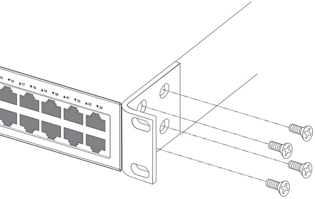
2. Attach the mounting brackets to the sides of the device.
NOTE
FCX624-E, FCX624-I, FCX648-E, and FCX648-I device brackets are mounted using three screws.
FIGURE 26 Attaching the brackets for the Brocade FCX 624S, FCX 648S, FCX 624S-F, FCX 624S-HPOE, and FCX 648S-
HPOE devices
Preparing the installation site
Brocade FCX Series Hardware Installation Guide
Part Number: 53-1003616-03 39
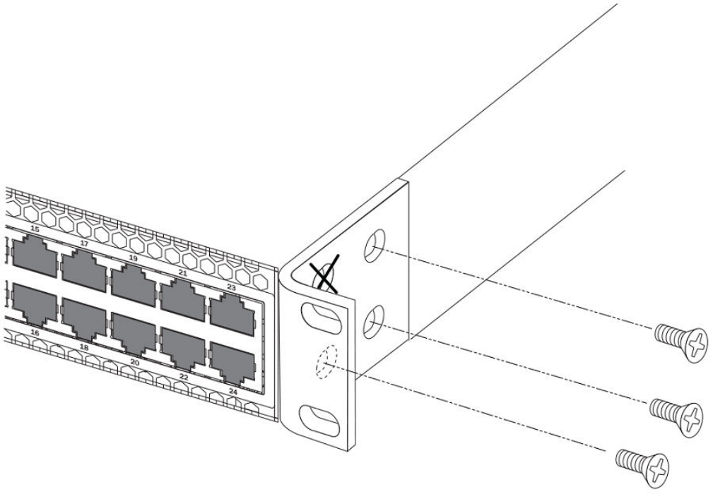
FIGURE 27 Attaching the brackets for the FCX624-E, FCX624-I, FCX648-E, and FCX648-I devices
Preparing the installation site
Brocade FCX Series Hardware Installation Guide
40 Part Number: 53-1003616-03
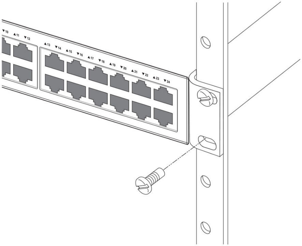
3. Attach the device in the rack.
FIGURE 28 Installing the device in a rack
4. If installing a single switch only, proceed to Powering on the system on page 47.
5. If installing multiple switches, mount them in the rack, one below the other, in any order.
Connecting devices in a traditional stack
Brocade FCX Series devices can operate as standalone devices and also as members of traditional stacks. A stack is a group of
devices--Brocade stackable units and their connected stacking links--that are connected so that the stack is managed as a single entity.
A traditional stack contains devices from only one model in a product family. A traditional stack can contain FCX S, FCX S-F, FCS E, and
FCX I devices.
Connecting devices in a traditional stack
Brocade FCX Series Hardware Installation Guide
Part Number: 53-1003616-03 41
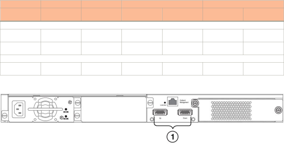
Stacking ports
This section summarizes the default stacking ports and the ports that can be used as stacking ports on Brocade FCX Series devices.
Default stacking ports have the capability to accept special stacking packets during a CLI-initiated command sequence of the Secure
Setup utility. Stacking ports can also be used as data ports.
The default stacking ports on FCX S/S-F devices are the ports in the 16/10 Gbps CX4 stacking module on the rear panel. The default
stacking ports on the FCX E/I devices are the rst two ports in the four-port 10 Gbps SFP+ module on the front panel.
Refer to the table below for the list of supported XFP transceivers (for stacking and non-stacking FCX models) and supported SFP and
SFP+ transceivers.
TABLE 16 Stacking ports on Brocade FCX Series devices
Stacking ports Data ports
Panel/slot Ports Default stacking Can be data ports Default data Can be stacking
ports
FCX S/S-F
16/10 Gbps CX4
stacking module
Rear/2 1,2 Yes: 1, 2 Yes
2-port 10 Gbps
XFP module
Front/3 1,2 Yes: 1, 2 Yes: 1, 2
FCX E/I
4-port 10 Gbps
SFP+ module
Front/2 1-4 Yes: 1, 2 Yes Yes: 3, 4 Yes
FIGURE 29 16/10 Gbps CX4 stacking module on the rear panel of FCX S/S-F devices
1. 16/10 Gbps CX4 stacking ports
Connecting devices in a traditional stack
Brocade FCX Series Hardware Installation Guide
42 Part Number: 53-1003616-03
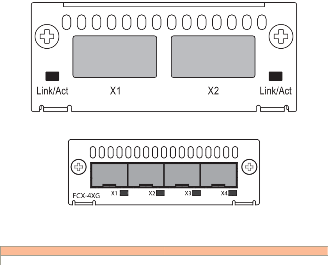
FIGURE 30 Two-port 10 Gbps XFP module on the front panel of FCX S/S-F devices
FIGURE 31 Four-port 10 Gbps SFP+ module on the front panel of FCX E/I devices
To connect FCX E/I devices and FCX S/S-F devices in a stack, you connect a 10 Gbps module on one device to a 10 Gbps module on
anther device. You cannot connect the 4-port 10 Gbps SFP+ module (FCX E/I) to the 16/10 Gbps CX4 stacking module (FCX S/S-F).
TABLE 17 Modules that connect FCX E/I and FCX S/S-F devices in a stack
This FCX E/I module connects to These FCX S/S-F modules
4-port 10 Gbps SFP+ module 2-port 10 Gbps XFP module
NOTE
Trunking is not supported on the Brocade FCX Series.
Stacking conguration requirements
• Before conguring the stack using the CLI, physically connect the devices using stacking cables.
• To connect FCX S/S-F, and FCX E/I devices in a stack, you must recongure the default stacking ports on the FCX S/S-F
devices to be the ports on the two-port 10 Gbps XFP module on the front panel using the default-port command.
• To use the ports in the 16/10 Gbps CX4 stacking module as data ports, you must recongure the stacking ports using the
longpreamble command.
Connecting devices in a traditional stack
Brocade FCX Series Hardware Installation Guide
Part Number: 53-1003616-03 43

• To change the default stacking ports on the 4-port 10 Gbps SFP+ module from ports 1 and 2 to ports 3 and 4, you must
recongure the default ports using the default-port command.
For information about conguring a stack, refer to the FastIron Ethernet Switch Stacking Conguration Guide.
Stacking cables
To connect Brocade FCX Series devices in a stack, you need to use specic cables.
TABLE 18 Cables used to connect Brocade FCX Series devices
To connect this FCX device To this FCX device Use this cable type
FCX S/S-F FCX S/S-F CX4 stacking cable
FCX E/I FCX E/I LC-LC MM ber cables
FCX S/S-F FCX E/I LC-LC MM ber cables
Stack size
A traditional stack can contain a combined maximum of eight FCX S, FCX S-F, FCS-E, and FCX-I devices.
Stacking topologies
Both linear and ring topologies are supported. In a linear stack topology there is a connection between each switch that carries two-way
communications across the stack. This connection can use one port or two ports per trunk.
For example, in a four-unit stack using a linear topology, unit 1 connects to unit 2, unit 2 to unit 3, and unit 3 to unit 4.
In ring stack topology, there is an extra connection between the logical rst and last devices forming a "ring" or "closed-loop." The closed-
loop connection provides a redundant path for the stack link, so if one link fails, stack communications can be maintained.
For example, in a four-unit stack using a ring topology, unit 1 connects to unit 2, unit 2 to unit 3, unit 3 to unit 4, and unit 4 connects to
unit 1.
Connecting devices in a traditional stack
Brocade FCX Series Hardware Installation Guide
44 Part Number: 53-1003616-03
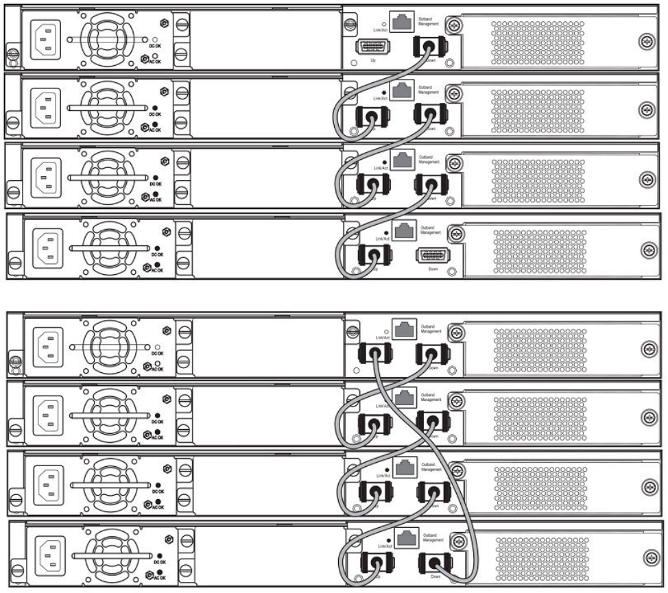
FIGURE 32 FCX S devices in linear (top) and ring (bottom) stacking topologies
Connecting devices in a traditional stack
Brocade FCX Series Hardware Installation Guide
Part Number: 53-1003616-03 45
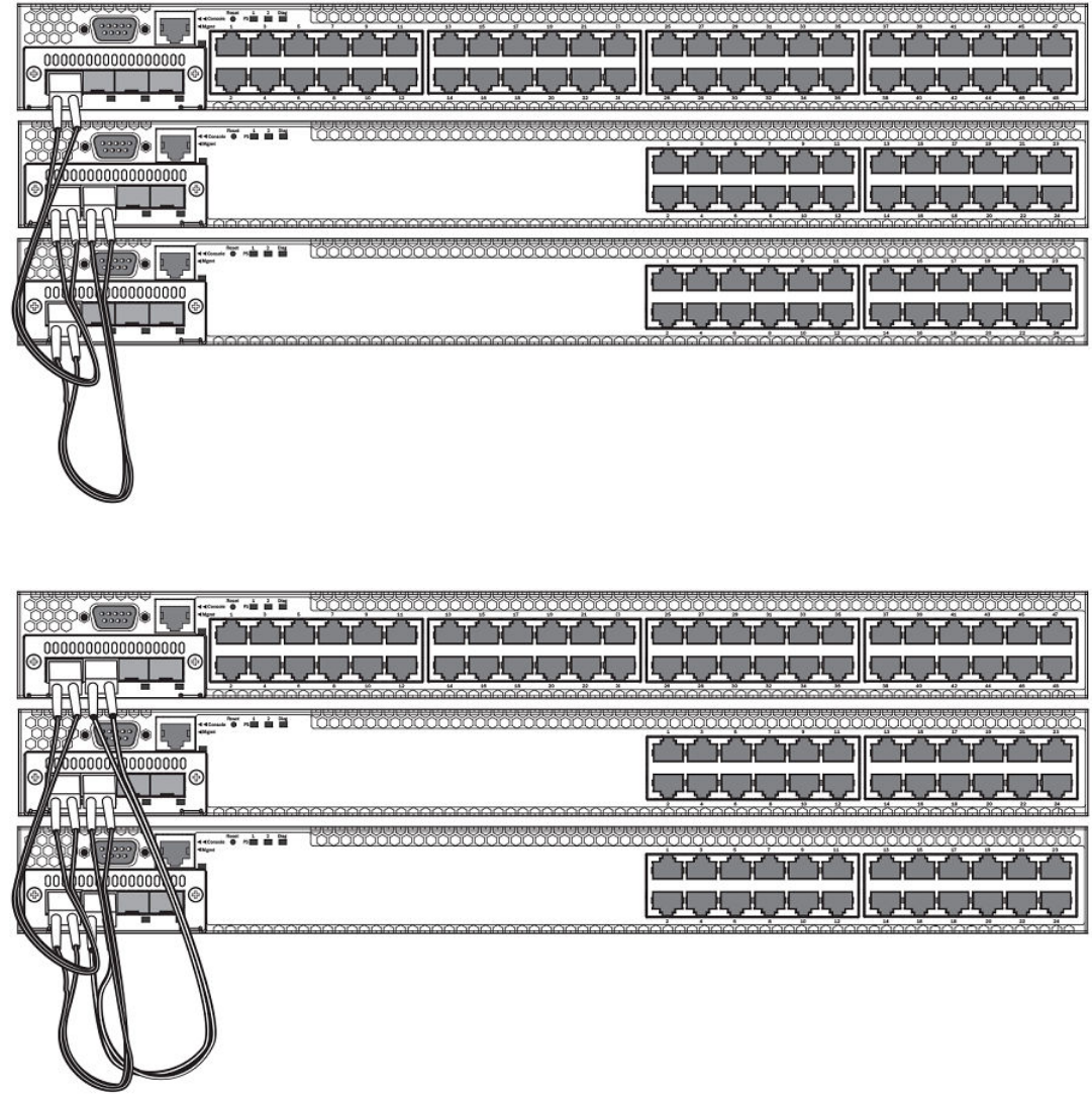
FIGURE 33 FCX E devices in a linear stacking topology
FIGURE 34 FCX E devices in a ring stacking topology
Connecting devices in a traditional stack
Brocade FCX Series Hardware Installation Guide
46 Part Number: 53-1003616-03
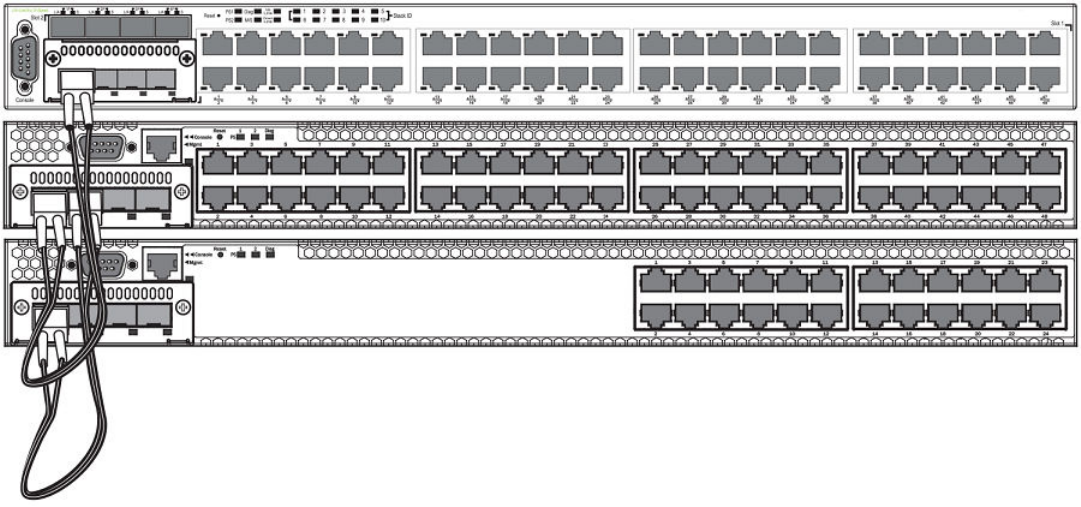
FIGURE 35 FCX S (top) and FCX E devices (bottom two devices) in a linear stacking topology
Extended distance stacking
Extended distance stacking allows stacking of devices in a distributed network environment. You can form a stack of co-located devices
or devices located over an extended distance to form a distributed stack. Extended distance stacking provides resiliency, scalability, and
ease of management whether the location of switches is in the same equipment rack or distributed across a network.
Currently, stacking is supported by way of CX4 up to 3 meters each, by way of 10 Gbps twinaxial xed copper up to 5 meters each, and
by way of optical stacking with the 10 Gbps SR or 10 Gbps MMF. The stacking range is 300 m for SR, 220 m for MMF, and 100 m for
10 Gbps USR SFP+. LR, ER, ZR, and ZRD optics are not supported for stacking.
To set up extended distance stacking, use ber-optic cables to connect the devices in a stack. Contact your Brocade representative for
information about supported ber-optic cables and distances.
Powering on the system
After you complete the physical installation, you can power on the system.
1. Remove the power cable from the shipping package.
2. Attach the AC power cable to the AC connector on the rear panel.
Powering on the system
Brocade FCX Series Hardware Installation Guide
Part Number: 53-1003616-03 47
3. Insert the power cable plug into a 115V, 120V, or 240V outlet.
NOTE
To turn the system o, simply unplug the power cable or
cables.
NOTE
The socket should be installed near the equipment and should be easily accessible.
NOTE
If the outlet is not rated 115/120V, stop and get the appropriate cable for the outlet.
Attaching a PC or terminal
To assign an IP address, you must have access to the Command Line Interface (CLI) . The CLI is a text-based interface that can be
accessed through a direct serial connection to the device and through Telnet connections.
Access the CLI by attaching a serial cable to the Console port. After you assign an IP address, you can access the system through Telnet
or Brocade Network Advisor.
Use the following steps to attach a management station to the serial port.
1. Connect a PC or terminal to the serial port of the system using a straight-through cable. The serial port has a male DB-9
connector.
NOTE
You need to run a terminal emulation program on the PC.
Attaching a PC or terminal
Brocade FCX Series Hardware Installation Guide
48 Part Number: 53-1003616-03
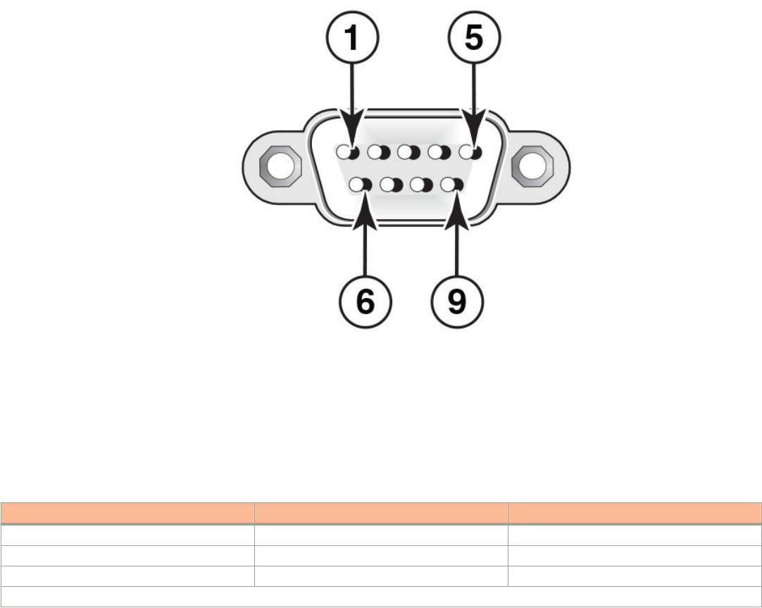
2. Launch the terminal emulation program and set the following session parameters:
• – Baud: 9600 bps
– Data bits: 8
– Parity: None
– Stop bits: 1
– Flow control: None
The EIA or TIA 232 serial communication port serves as a connection point for management by a PC or SNMP workstation.
Brocade devices come with a standard male DB-9 connector.
FIGURE 36 Serial Port (DB-9 DTE) Pin-Out
Most PC serial ports also require a cable with a female DB-9 connector. Terminal connections will vary, requiring either a DB-9
or DB-25 connector, male or female. For more information about serial cable options between a Brocade device and a PC or
terminal, see Wiring map for serial cable on page 49.
Wiring map for serial cable
TABLE 19 Serial cable wiring
Switch 9-Pin Serial Port Null Modem PC 9-Pin DTE Port
2 TXD (transmit data) ----------------------------> 2 RXD (receive data)
3 RXD (receive data) <---------------------------- 3 TXD (transmit data)
5 SGND (signal ground) <--------------------------> 5 SGND (signal ground)
No other pins are used.
NOTE
As indicated in the table above, some of the wires should not be connected.
Attaching a PC or terminal
Brocade FCX Series Hardware Installation Guide
Part Number: 53-1003616-03 49
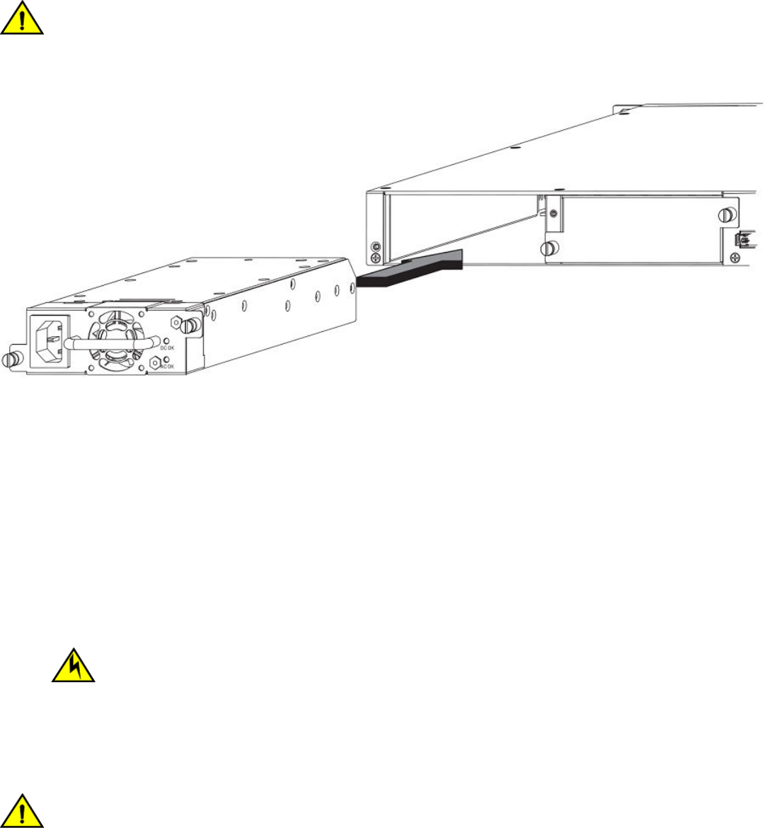
Installing and replacing a power supply unit
CAUTION
Ensure that the airow direction of the power supply unit matches that of the installed fan tray. The power supplies and fan
trays are clearly labeled with either a green arrow with an "E", or an orange arrow with an "I."
FIGURE 37 Installing a power supply unit
Use the following steps to install a power supply unit in the switch.
1. Remove the blank metal plate (or a previously installed PSU) from the appropriate slot by removing the two screws with a at-
head screwdriver.
2. Before opening the package that contains the PSU, touch the bag to the switch casing to discharge any potential static
electricity. Brocade recommends using an ESD wrist strap during installation.
3. Remove the PSU from the anti-static shielded bag.
4. Holding the PSU level, guide it into the carrier rails on each side and gently push it all the way into the slot, ensuring that it rmly
engages with the connector.
5. When you are sure the PSU has properly engaged the connector, tighten the retainer screws to secure the in PSU the slot.
When the device is powered on, the PSU AC and DC LEDs on the PSU back panel should turn green to conrm that the PSU
is correctly installed and supplying power.
CAUTION
If you do not install a module or a power supply in a slot, you must keep the slot ller panel in place. If you run the
chassis with an uncovered slot, the system will overheat.
Installing or replacing fan trays
CAUTION
Ensure that the airow direction of the power supply unit matches that of the installed fan tray. The power supplies and fan
trays are clearly labeled with either a green arrow with an "E", or an orange arrow with an "I."
Installing and replacing a power supply unit
Brocade FCX Series Hardware Installation Guide
50 Part Number: 53-1003616-03
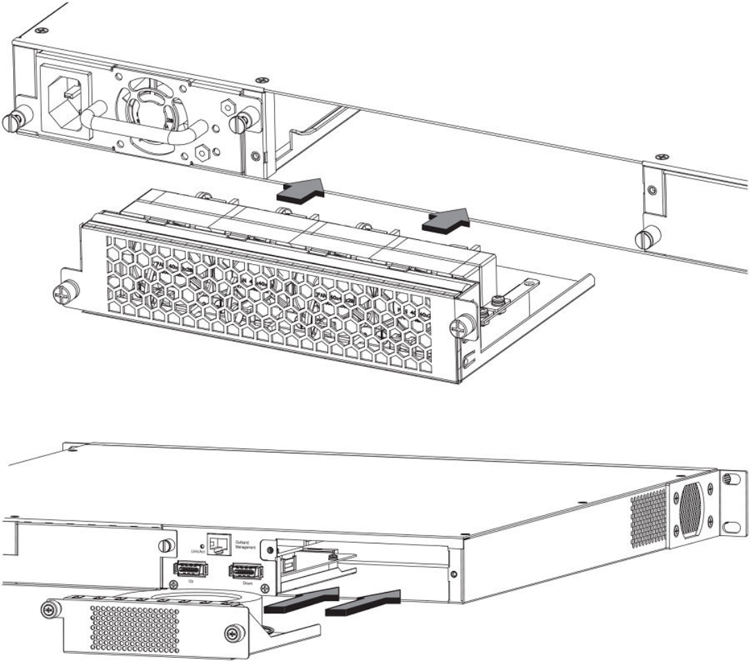
NOTE
For FCX624-E, FCX624-I, FCX648-E, and FCX648-I devices, the fan trays are hot-swappable.
FIGURE 38 Installing a fan tray on FCX624-E, FCX624-I, FCX648-E, and FCX648-I devices
FIGURE 39 Installing a fan tray on Brocade FCX 624S, FCX 648S, FCX 624S-F, FCX 624S-HPOE, and FCX 648S-HPOE devices
Perform the following steps to install a fan tray in the switch.
1. Remove the installed fan tray from the slot by removing the two screws with a crosshead or Philips screwdriver.
2. Before opening the package that contains the new fan tray, touch the bag to the switch casing to discharge any potential static
electricity. It is recommended that you wear an ESD wrist strap during installation.
3. Remove the fan tray from the anti-static shielded bag.
Installing or replacing fan trays
Brocade FCX Series Hardware Installation Guide
Part Number: 53-1003616-03 51
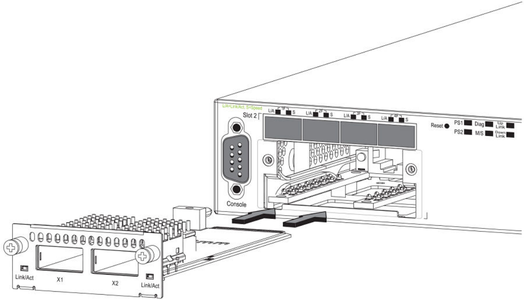
4. Holding the fan tray level, guide it into the carrier rails on each side and gently push it all the way into the slot, ensuring that it
rmly engages with the connector.
5. When you are sure the fan tray has properly engaged the connector, tighten the retainer screws to secure the fan tray in the slot.
NOTE
The fans are controlled by software, and their speed is set according to the environmental temperature surrounding the
switch.
Installing an optional module
Brocade FCX 624S, FCX 648S, FCX 624S-F, FCX 624S-HPOE, and FCX 648S-HPOE switches support an optional two-port 10
Gbps Ethernet XFP module. Brocade recommends that the system is powered down for installation as the 2x10 XFP module is not hot
swapable.
FIGURE 40 Installing an optional module on Brocade FCX 624S, FCX 648S, FCX 624S-F, FCX 624S-HPOE, and FCX 648S-HPOE
devices
FCX624-E, FCX624-I, FCX648-E, and FCX648-I switches support an optional four-port 1 Gbps SFP module or four-port 10 Gbps
SFP+ module. The 10 Gbps SFP+ module allows you to use your device in a stack.
On FCX624-E, FCX624-I, FCX648-E, and FCX648-I switches, optional SFP and SFP+ modules are not hot-swappable.
Installing an optional module
Brocade FCX Series Hardware Installation Guide
52 Part Number: 53-1003616-03
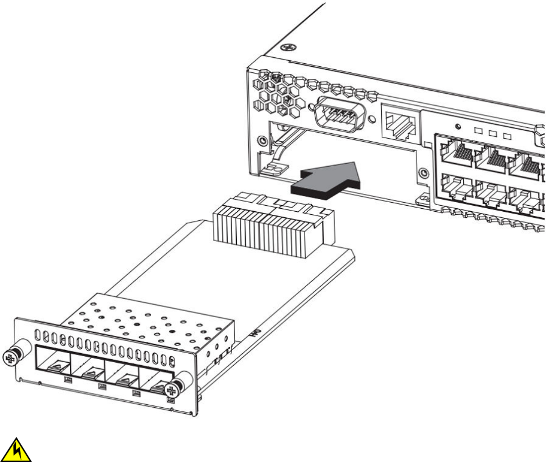
FIGURE 41 Installing an optional module in FCX624-E, FCX624-I, FCX648-E, and FCX648-I devices
CAUTION
Be sure to power-down your device before you install or replace a module.
Perform these steps to install an optional module.
1. Remove the blank metal plate (or an installed module) from the slot by removing the two screws with a Phillips screwdriver.
2. Before opening the package that contains the module, touch the bag to the switch casing to discharge any potential static
electricity. It is recommended that you wear an ESD wrist strap during installation.
3. Remove the module from the anti-static shielded bag.
4. Holding the module level, guide it into the carrier rails on each side and gently push it all the way into the slot, ensuring that it
rmly engages with the connector.
5. When you are sure the module has properly engaged the connector, tighten the retainer screws to secure the module in the slot.
Installing an optional module
Brocade FCX Series Hardware Installation Guide
Part Number: 53-1003616-03 53

6. When the switch is powered on, the LEDs will function as described in –Port, system, and power status LEDs for Brocade FCX
624S, FCX 648S, FCX 624S-F, FCX 624S-HPOE, and FCX 648S-HPOE on page 26.
CAUTION
If you do not install a module or a power supply in a slot, you must keep the slot ller panel in place. If you run the
chassis with an uncovered slot, the system will overheat.
Optional 2-port 10 Gbps SFP+ uplink module
Feature description for the 2-port 10 Gbps SFP+ module including modied CLI examples
The following Brocade FCX devices include a slot on the front panel for a two-port 10 Gbps SPF+ uplink module. This module operates
at 10 Gbps full duplex.
• Brocade FCX 624S
• Brocade FCX 648S
• Brocade FCX 624S-F
• Brocade FCX 624S-HPOE
• Brocade FCX 648S-HPOE
The 2-port 10 Gbps SPF+ uplink module can replace the 2-port XFP module in the xed slot 3. Port mapping is the same as for the
2x10 XFP with slot 3 and port 1 or 2, for example, 1/3/1 and 1/3/2. Stacking is supported using the stack default-port command with
the 1/3/1 and 1/3/2 options.
The module is named FCX-2SFPP 2-port 10G Module (2-SFP+) in conguration and output.
Follow these steps to replace the 2x10 SFP+ module:
1. Remove any xed LAG conguration.
2. Power down only the member switch in the stack because the 2x10 SFP+ module is not hot-swappable. However, the links in
the old 2x10 SFP+ module will be in up state for a short duration.
3. Insert the new 2x10 SFP+ module.
4. Power on the member switch in the stack.
5. In active/standby, reload the complete stack.
NOTE
There should not be any trac injection until you reload the stack and the links are up
again.
6. Recongure the xed LAGs.
Installing an optional module
Brocade FCX Series Hardware Installation Guide
54 Part Number: 53-1003616-03

FIGURE 42 Two-port 10 Gbps SFP+ module
TABLE 20 10 Gbps SFP+ module port status LEDs
LED Condition Status
Link or Act LED (Link or Activity) On or ashing green Port has a valid link at 10 Gbps. Flashing indicates
activity.
O The port is down.
Installing an optional module
Brocade FCX Series Hardware Installation Guide
Part Number: 53-1003616-03 55
Modied CLI examples for the 2-port 10 Gbps SFP+ module
The following sample output from the show module command displays an entry for the 2-port 10 Gbps SFP+ module.
device# show module
Module Status Ports Starting MAC
U1:M1 FCX-48GS POE 48-port Management Module OK 48 0024.38c9.4d00
U1:M2 FCX-2XGC 2-port 16G Module (2-CX4) OK 2 0024.38c9.4d31
U1:M3 FCX-2SFPP 2-port 10G Module (2-SFP+) OK 2 0024.38c9.4d33
The following sample output from the show version command shows that the 2-port 10 Gbps SFP+ module is in slot 3.
device# show version
Copyright (c) 1996-2011 Brocade Communications Systems, Inc.
UNIT 1: compiled on Oct 18 2012 at 16:01:04 labeled as FCXS07300b1
(5373912 bytes) from Primary FCXS07300b1.bin
SW: Version 07.3.00b1T7f1
Boot-Monitor Image size = 370663, Version:07.3.00T7f5 (grz07300b1)
HW: Stackable FCX648S-HPOE-PREM (PROM-TYPE FCX-ADV-U)
==========================================================================
UNIT 1: SL 1: FCX-48GS POE 48-port Management Module
Serial #: BCYXXXXXXXX
License: BASE_SOFT_PACKAGE (LID: deaHHJIhFNb)
P-ENGINE 0: type DB90, rev 01
P-ENGINE 1: type DB90, rev 01
PROM-TYPE: FCX-ADV-U
==========================================================================
UNIT 1: SL 2: FCX-2XGC 2-port 16G Module (2-CX4)
==========================================================================
UNIT 1: SL 3: FCX-2SFPP 2-port 10G Module (2-SFP+)
==========================================================================
800 MHz Power PC processor 8544E (version 0021/0022) 400 MHz bus
65536 KB flash memory
256 MB DRAM
STACKID 1 system uptime is 2 days 10 minutes 24 seconds
The system : started=warm start reloaded=by "reload"
The following is sample output of the show running-cong command.
device# show running-config
!
Startup-config data location is flash memory
!
Startup configuration:
!
ver 07.3.00a001T7f1
!
stack unit 1
module 1 fcx-48-poe-port-management-module
module 2 fcx-cx4-2-port-16g-module
module 3 fcx-sfpp-2-port-10g-module
!
The following is sample output of the show media and show optic commands with some conguration.
device# show media
1/1/1:C 1/1/2:C 1/1/3:C 1/1/4:C 1/1/5:C 1/1/6:C 1/1/7:C 1/1/8:C
1/1/9:C 1/1/10:C 1/1/11:C 1/1/12:C 1/1/13:C 1/1/14:C 1/1/15:C 1/1/16:C
1/1/17:C 1/1/18:C 1/1/19:C 1/1/20:C 1/1/21:C 1/1/22:C 1/1/23:C 1/1/24:C
1/1/25:C 1/1/26:C 1/1/27:C 1/1/28:C 1/1/29:C 1/1/30:C 1/1/31:C 1/1/32:C
1/1/33:C 1/1/34:C 1/1/35:C 1/1/36:C 1/1/37:C 1/1/38:C 1/1/39:C 1/1/40:C
1/1/41:C 1/1/42:C 1/1/43:C 1/1/44:C 1/1/45:C 1/1/46:C 1/1/47:C 1/1/48:C
1/2/1:XG-CX4 1/2/2:XG-CX4
1/3/1:XG-SR 1/3/2:XG-SR
device# show media e 1/3/1
Port 1/3/1: Type : 10G XG-SR(SFP +)
Vendor: Brocade Version: 1
Part# : PLRXPLSCS4371 Serial#: CXXXXXXXX
device(config)# op 1
Enable optical monitoring and set alarm/warn interval to 1 minute(s)
Installing an optional module
Brocade FCX Series Hardware Installation Guide
56 Part Number: 53-1003616-03
device(config)# show optic 1/3/1
Port Temperature Tx Power Rx Power Tx Bias Current
+----+-----------+--------------+--------------+---------------+
1/3/1 32.7421 C -002.3195 dBm -002.5947 dBm 6.212 mA
Normal Normal Normal Normal
device# show media e 1/3/1
Port 1/3/1: Type : 10G XG-ER(SFP +)
Vendor: BROCADE Version: A
Part# : 57-0000085-01 Serial#: XXXXXXXXXXXXXXX
device# show media e 1/3/2
Port 1/3/2: Type : 10G XG-USR (SFP +)
Vendor: BROCADE Version: A
Part# : 57-1000130-01 Serial#: XXXXXXXXXXXXXXX
device# show media
1/1/1:C 1/1/2:C 1/1/3:C 1/1/4:C 1/1/5:C 1/1/6:C 1/1/7:C 1/1/8:C
1/1/9:C 1/1/10:C 1/1/11:C 1/1/12:C 1/1/13:C 1/1/14:C 1/1/15:C 1/1/16:C
1/1/17:C 1/1/18:C 1/1/19:C 1/1/20:C 1/1/21:C 1/1/22:C 1/1/23:C 1/1/24:C
1/1/25:C 1/1/26:C 1/1/27:C 1/1/28:C 1/1/29:C 1/1/30:C 1/1/31:C 1/1/32:C
1/1/33:C 1/1/34:C 1/1/35:C 1/1/36:C 1/1/37:C 1/1/38:C 1/1/39:C 1/1/40:C
1/1/41:C 1/1/42:C 1/1/43:C 1/1/44:C 1/1/45:C 1/1/46:C 1/1/47:C 1/1/48:C
1/2/1:XG-CX4 1/2/2:XG-CX4
1/3/1:XG-ER 1/3/2:XG-USR
Installing an optional module
Brocade FCX Series Hardware Installation Guide
Part Number: 53-1003616-03 57
Brocade FCX Series Hardware Installation Guide
58 Part Number: 53-1003616-03

Checking Network Devices and Testing
Connectivity
• Assigning permanent passwords................................................................................................................................................................59
•Conguring IP addresses...............................................................................................................................................................................60
• Testing connectivity.......................................................................................................................................................................................... 72
• Troubleshooting network connections......................................................................................................................................................76
DANGER
The procedures in this manual are for qualied service personnel.
Assigning permanent passwords
By default, the CLI is not protected by passwords. To secure CLI access, Brocade strongly recommends assigning passwords. See the
FastIron Ethernet Switch Administration Guide.
NOTE
You can assign passwords using Brocade Network Advisor if an enable password for a Super User has been congured on the
device.
The CLI contains the following access levels:
• User EXEC - The level you enter when you rst start a CLI session. At this level, you can view some system information but you
cannot congure system or port parameters.
• Privileged EXEC - This level is also called the Enable level and can be secured by a password. You can perform tasks such as
manage les on the ash module, save the system conguration to ash, and clear caches at this level.
• CONFIG - The conguration level. This level lets you congure the system IP address and congure switching and routing
features. To access the CONFIG mode, you must already be logged into the Privileged level of the EXEC mode.
You can set the following levels of Enable passwords:
• Super User - Allows complete read-and-write access to the system. This is generally for system administrators and is the only
password level that allows you to congure passwords.
NOTE
You must set a Super User password before you can set other types of passwords.
• Port Conguration - Allows read-and-write access for specic ports but not for global (system-wide) parameters.
• Read Only - Allows access to the Privileged EXEC mode and CONFIG mode but only with read access.
Setting passwords
1. At the opening CLI prompt, enter the following command to change to the Privileged level of the EXEC mode:
device> enable
Brocade FCX Series Hardware Installation Guide
Part Number: 53-1003616-03 59
2. Access the CONFIG level of the CLI by entering the following command:
device# configure terminal
device(config)#
3. Enter the following command to set the super user password:
device(config)# enable super-user-password
text
NOTE
You must set the super user password before you can set other types of passwords.
4. Enter the following commands to set the port conguration and read-only passwords:
device(config)# enable port-config-password
text
device(config)# enable read-only-password
text
NOTE
If you forget your super user password, refer to Recovering from a lost password on page 60.
Syntax: enable super-user-password | read-only-password | port-cong-password text
Passwords can be up to 32 characters long.
Recovering from a lost password
By default, the CLI does not require passwords. However, if someone has congured a password for the device but the password has
been lost, you can regain super user access to the device using the following procedure.
NOTE
Recovery from a lost password requires direct access to the serial port and a system reset.
Use the following procedure to recover from a lost password.
1. Start a CLI session over the serial interface to the Brocade device.
2. Reboot the device.
3. While the system is booting, before the initial system prompt appears, enter b to enter the boot monitor mode.
4. Enter no password at the prompt. (You cannot abbreviate this command.)
5. Enter boot system ash primary at the prompt. This command causes the device to bypass the system password check.
After the console prompt reappears, assign a new password.
Conguring IP addresses
You must congure at least one IP address using the serial connection to the CLI before you can manage the system using the other
management interfaces.
Brocade devices support both classical IP network masks (Class A, B, and C subnet masks, and so on) and Classless Interdomain
Routing (CIDR) network prex masks.
• To enter a classical network mask, enter the mask in IP address format. For example, enter "10.157.22.99 255.255.255.0" for
an IP address with a Class-C subnet mask.
Conguring IP addresses
Brocade FCX Series Hardware Installation Guide
60 Part Number: 53-1003616-03

• To enter a prex number for a network mask, enter a forward slash ( / ) and the number of bits in the mask immediately after the
IP address. For example, enter "209.157.22.99/24" for an IP address that has a network mask with 24 signicant ("mask")
bits.
By default, the CLI displays network masks in classical IP address format (example: 255.255.255.0). You can change the display to the
prex format. Refer to the FastIron Ethernet Switch Administration Guide.
Devices running Layer 2 software
Use the following procedure to congure an IP Address on a device running Layer 2 software.
1. At the opening CLI prompt, enter enable.
device> enable
2. Enter the following command at the Privileged EXEC level prompt (for example, Brocade#), then press Enter This command
erases the factory test conguration if still present:
device# erase startup-config
CAUTION
Use the erase startup-cong command only for new systems. If you enter this command on a system you have
already congured, the command erases the conguration. If you accidentally do erase the conguration on a
congured system, enter the write memory command to save the running conguration to the startup-cong le.
3. Access the conguration level of the CLI by entering the following command:
device# configure terminal
(Privileged EXEC Level)
device(config)# (Global CONFIG Level)
4. Congure the IP address and mask for the switch.
device(config)# ip address 10.22.3.44 255.255.255.0
5. Set a default gateway address for the switch.
device(config)# ip default-gateway 10.22.3.1
NOTE
You do not need to assign a default gateway address for single subnet networks.
Syntax: enable [ password ]
Syntax: congure terminal
Syntax: [no] ip address ip-addr ip-mask
or
Syntax: [no] ip address ip-addr/mask-bits
Syntax: ip default-gateway ip-addr
Conguring IP addresses
Brocade FCX Series Hardware Installation Guide
Part Number: 53-1003616-03 61

Devices running Layer 3 software
Before attaching equipment to a Brocade Layer 3 Switch, you must assign an interface IP address to the subnet on which the router will
be located. You must use the serial connection to assign the rst IP address. For subsequent addresses, you also can use the CLI
through Telnet.
By default, you can congure up to 24 IP interfaces on each port, virtual interface, and loopback interface. You can increase this amount
to up to 64 IP subnet addresses per port by increasing the size of the subnet-per-interface table.
The following procedure shows how to add an IP address and mask to a router port.
1. At the opening CLI prompt, enter enable .
device> enable
2. Enter the following command at the CLI Privileged EXEC level prompt, then press Enter. This command erases the factory test
conguration if still present:
device# erase startup-config
CAUTION
Use the erase startup-cong command only for new systems. If you enter this command on a system you have
already congured, the command erases the conguration. If you accidentally do erase the conguration on a
congured system, enter the write memory command to save the running conguration to the startup-cong le.
3. Access the conguration level of the CLI by entering the following command:
device# configure terminal
(Privileged EXEC Leve)l
device(config)# (Global CONFIG Level)
4. Congure the IP addresses and mask addresses for the interfaces on the router.
device(config)# int e 1/1/2
device(config-if-e1000-1/1/2)# ip address 10.22.3.44
255.255.255.0
NOTE
You can use the syntax ip addressip-addr /mask-bits if you know the subnet mask length. In the preceding example,
you could enter ip address 10.22.3.44 /24 .
Syntax: enable [ password ]
Syntax: congure terminal
Syntax: [no] ip address ip-addr ip-mask [ secondary ]
or
Syntax: [no] ip address ip-addr/mask-bits [ secondary ]
Use the secondary parameter if you have already congured an IP address within the same subnet on the interface.
Conguring IP parameters for devices running Layer 3 software
This section describes how to congure IP parameters for devices running Layer 3 software.
Conguring IP addresses
Brocade FCX Series Hardware Installation Guide
62 Part Number: 53-1003616-03
Conguring IP addresses
You can congure an IP address on the following types of Layer 3 switch interfaces:
• Ethernet port
• Virtual routing interface (also called a Virtual Ethernet or "VE")
• Loopback interface
By default, you can have up to 24 IP addresses on each interface, but you can increase this number to 128 IP addresses.
NOTE
Once you congure a virtual routing interface on a VLAN, you cannot congure Layer 3 interface parameters on individual
ports in the VLAN. Instead, you must congure the parameters on the virtual routing interface itself.
Brocade devices support both classical IP network masks (Class A, B, and C subnet masks, and so on) and Classless Interdomain
Routing (CIDR) network prex masks.
• To enter a classical network mask, enter the mask in IP address format. For example, enter "10.157.22.99 255.255.255.0" for
an IP address with a Class-C subnet mask.
• To enter a prex network mask, enter a forward slash ( / ) and the number of bits in the mask immediately after the IP address.
For example, enter "10.157.22.99/24" for an IP address that has a network mask with 24 signicant bits (ones).
By default, the CLI displays network masks in classical IP address format (for example: 255.255.255.0). You can change the display to
prex format.
Assigning an IP address to an Ethernet port
Enter the following commands to assign an IP address to port 1/1/1.
device(config)# interface ethernet 1/1/1
device(confi-if-1/1/1)#FLS Router ip address 10.45.6.1 255.255.255.0
You also can enter the IP address and mask in CIDR format, as follows:
device(confi-if-1/1/1)# ip address 10.45.6.1/24
Syntax: [no] ip address ip-addr ip-mask
or
Syntax: [no] ip address ip-addr/mask-bits
Assigning an IP address to a loopback interface
Loopback interfaces are always up, regardless of the states of physical interfaces. They can add stability to the network because they are
not subject to route ap problems that can occur due to unstable links between a Layer 3 Switch and other devices. You can congure up
to four loopback interfaces on a Layer 3 switch.
You can add up to 24 IP addresses to each loopback interface.
NOTE
If you congure the Brocade switch to use a loopback interface to communicate with a BGP4 neighbor, you must also
congure a loopback interface on the neighbor and congure the neighbor to use that loopback interface to communicate with
theBrocade switch.
Conguring IP addresses
Brocade FCX Series Hardware Installation Guide
Part Number: 53-1003616-03 63
To add a loopback interface, enter commands such as those shown in the following example:
device(config)# exit
device(config)# interface loopback 1
device(config)# ip address 10.0.0.1/24
Syntax: interface loopback num
The num parameter species the virtual interface number. You can specify from 1 to the maximum number of virtual interfaces
supported on the device. To display the maximum number of virtual interfaces supported on the device, enter the show default values
command. The maximum is listed in the System Parameters section, in the Current column of the virtual-interface row.
Assigning an IP address to a virtual routing interface
A virtual interface is a logical port associated with a Layer 3 Virtual LAN (VLAN) congured on a Layer 3 switch. You can congure
routing parameters on the virtual interface to enable the Layer 3 switch to route protocol trac from one Layer 3 VLAN to the other,
without using an external router.
This section describes how to congure an IP address on a virtual interface.
NOTE
The switch uses the lowest MAC address on the device (the MAC address of port 1 or 1/1/1) as the MAC address for all ports
within all virtual interfaces you congure on the device.
Enter commands similar to the following to add a virtual interface to a VLAN and congure an IP address on the interface.
device(config)# vlan 2 name IP-Subnet_10.1.2.1/24
device(config)# untag 1/1/1 to 1/1/4
device(config)# router-interface ve1
device(config)# interface ve1
device(config)# ip address 10.1.2.1/24
The rst two commands in this example create a Layer 3 protocol-based VLAN name "IP-Subnet_10.1.2.1/24 " and add a range of
untagged ports to the VLAN. The router-interface command creates virtual interface 1 as the routing interface for the VLAN. The last
two commands change to the interface conguration level for the virtual interface and assign an IP address to the interface.
Syntax: router-interface ve num
Syntax: interface ve num
Deleting an IP address
Enter a command similar to the following to delete an IP address.
device(config-if-1/1/1)# no ip address 10.1.2.1
This command deletes IP address 10.1.2.1. You do not need to enter the subnet mask.
To delete all IP addresses from an interface, enter the following command:
device(config-if-1/1/1)# no ip address *
Syntax: [no] ip address ip-addr | *
Conguring IP addresses
Brocade FCX Series Hardware Installation Guide
64 Part Number: 53-1003616-03

Performing a factory reset
Resets the device to the default factory settings.
The following procedure applies to most managed switches and routers from a directly attached serial connection. Some commands
may vary between vendors.
1. At the opening CLI prompt, save the current conguration to a TFTP server or other remote device.
2. Enter the following command at the Privileged EXEC level prompt, then press Enter. This command erases the factory test
conguration if still present.
Brocade# erase startup-config
NOTE
Do not execute the write memory command.
NOTE
Use the erase startup-cong command only for new systems. If you enter this command on a system you have
already congured, the command erases the conguration. If you accidentally erase the conguration on a congured
system, and decide to abort this factory reset procedure, enter the write memory command to save the running
conguration to the startup-cong le.
3. Enter the following command at the Privileged EXEC level prompt, then press Enter:
Brocade# reload
NOTE
The device may throw a warning that the startup-cong cannot be found. This warning can be
ignored.
Once the device has nished reloading, it will be reset to "factory" settings.
4. Congure the device.
Connecting network devices
Brocade devices support connections to other vendors’ routers, switches, and hubs, as well as other Brocade devices.
Connectors
For port pinouts, refer to the Brocade FCX Series Technical Specications on page 89.
Cable specications
CAUTION
Before plugging a cable into to any port, be sure to discharge the voltage stored on the cable by touching the electrical
contacts to ground surface.
Refer to “Cable specications” for cable lengths and types.
Conguring IP addresses
Brocade FCX Series Hardware Installation Guide
Part Number: 53-1003616-03 65

Cable specications
This section lists the specications for the cables used with the 10/100 Ethernet ports. For information about supported transceivers,
refer to Fiber-optic transceivers on page 68.
For information about supported SFP and SFP+ transceivers, refer to the product data sheet.
NOTE
Cable installation and network conguration will aect overall transmission capability. The numbers provided in the following
table represent the accepted recommendations of the various standards. For network-specic recommendations, consult your
local Brocade reseller or system engineer.
TABLE 21 Cable length summary
Cable Type Connector Type Core
Diameter(microns)
Modal Bandwidth
(MHz*km) or
Wavelength (nm)
Range (meters)
1000Base-BX-D Single-mode Fiber
(SMF)
LC connector for SFP
module
9 1490 nm 2 - 10000 (10 km)
1000Base-BX-U SMF LC connector for SFP
module
9 1310 nm 2 - 10000 (10 km)
1000Base-LHA SMF LC connector for SFP
module
9 1550 nm 2 - 70000 (70 km)
1000Base-LHB SMF LC connector for SFP
module
9 1550 nm 2 - 120000 (120 km)
1000Base-LX Multi-mode Fiber
(MMF)
LC connector for SFP
module
62.5 500 2 - 550
MMF 50 400 2 - 550
MMF 50 500 2 - 550
SMF 9 1300 nm 2 - 10000
1000Base-SX MMF LC connector for SFP
module
62.5/125 200 .5 - 275
MMF 62.5/125 500 .5 - 550
MMF 50/125 900 .5 - 595
MMF 50/125 1500 .5 - 740
MMF 50/125 2000 .5 - 860
1000Base-T Copper RJ-45 jack for
standard unshielded
twisted pair (UTP or
Category 5)
n/a n/a up to 100 meters
100Base-FX MMF LC connector for SFP
module
62.5 500 up to 2000 (2 km)
100Base-FX-IR MMF SC 62.5 125 2 km (1.24 miles)
100Base-FX-LR SMF SC 9 125 20 km (12.43 miles)
10GBase-CX4 Inniband 4x copper XAUI connector n/a n/a up to 15
10G SFP+ TWNX SFP n/a n/a 1, 3, and 5
Connecting to Ethernet or Fast Ethernet hubs
For copper connections to Ethernet hubs, a 10/100BaseTX or 1000BaseT switch, or another Brocade device, a crossover cable is
required. If the hub is equipped with an uplink port, it will require a straight-through cable instead of a crossover cable.
Conguring IP addresses
Brocade FCX Series Hardware Installation Guide
66 Part Number: 53-1003616-03
NOTE
The 802.3ab standard (automatic MDI or MDIX detection) calls for automatic negotiation of the connection between two
1000Base-T ports. In this case a straight-through cable may work just as well as a crossover cable. For more information
about this feature, refer to the FastIron Ethernet Switch Security Conguration Guide.
FIGURE 43 UTP crossover cable
FIGURE 44 Straight-through cable
Conguring IP addresses
Brocade FCX Series Hardware Installation Guide
Part Number: 53-1003616-03 67

Connecting to workstations, servers, or routers
Straight-through UTP cabling is required for direct UTP attachment to workstations, servers, or routers using network interface cards
(NICs).
Fiber cabling is required for direct attachment to Gigabit NICs or switches and routers through ber ports. Refer to Connecting a network
device to a ber port on page 68.
Automatic MDI or MDIX detection
All 10/100 and Gbps Ethernet Copper ports on the devices support automatic Media Dependent Interface (MDI) and Media Dependent
Interface Crossover (MDIX) detection. This feature is enabled on all 10/100 and Gigabit copper ports by default. For each port, you can
disable auto MDI or MDIX, designate the port as an MDI port, or designate the port as an MDIX port.
For more information about this feature and how congure it, refer to FastIron Ethernet Switch Security Conguration Guide.
Connecting a network device to a ber port
For direct attachment from the device to a Gbps NIC, switch, or router, using a ber-optic transceiver, you will need ber cabling with an
LC connector.
To connect the device to another network device using a ber port, you must do the following tasks:
• Install a ber optic transceiver (XFP, SFP, or SFP+)
• Cable the ber optic transceiver
Fiber-optic transceivers
The following table lists supported XFP transceivers (for stacking and non-stacking FCX models) and supported SFP and SFP+
transceivers.
TABLE 22 Supported XFP transceivers for Brocade FCX 624S, FCX 648S, FCX 624S-F, FCX 624S-HPOE, and FCX 648S-HPOE
devices
10 Gigabit Optic Distance Supported for stacking
10GBase-SR 300 m Yes
10GBase-LR 10 km No
10GBase-ER 40 km No
10GBase-LRM (1310-MMF) 200 m No
TABLE 23 Supported SFP transceivers for FCX624-E, FCX624-I, FCX648-E, and FCX648-I devices
10 Gigabit Optic Distance Supported for stacking
10GSFPP-SR 300 m Yes
10GSFPP-LR 10 km No
Installing a transceiver
You can install a new transceiver in an XFP, SFP, or SFP+ slot while the device is powered on and running.
While installing a transceiver, wear an ESD wrist strap with a plug for connection to a metal surface.
Conguring IP addresses
Brocade FCX Series Hardware Installation Guide
68 Part Number: 53-1003616-03

DANGER
For safety reasons, the ESD wrist strap should contain a series 1 megaohm resistor.
DANGER
All ber-optic interfaces use Class 1 lasers.
Use the following setps to install a transceiver.
1. Put on the ESD wrist strap and ground yourself by attaching the clip end to a metal surface (such as an equipment rack) to act
as ground.
2. Remove the new transceiver from the protective packaging.
Conguring IP addresses
Brocade FCX Series Hardware Installation Guide
Part Number: 53-1003616-03 69
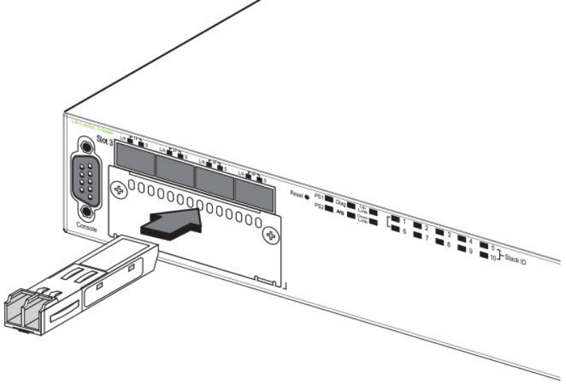
3. Gently insert the transceiver into the slot until it clicks into place. Transceivers are keyed to prevent incorrect insertion.
FIGURE 45 Installing a transceiver into FCX-624S, FCX-648S, FCX-624S, FCX-624S-HPOE, and FCX-648S-HPOE
devices
Conguring IP addresses
Brocade FCX Series Hardware Installation Guide
70 Part Number: 53-1003616-03
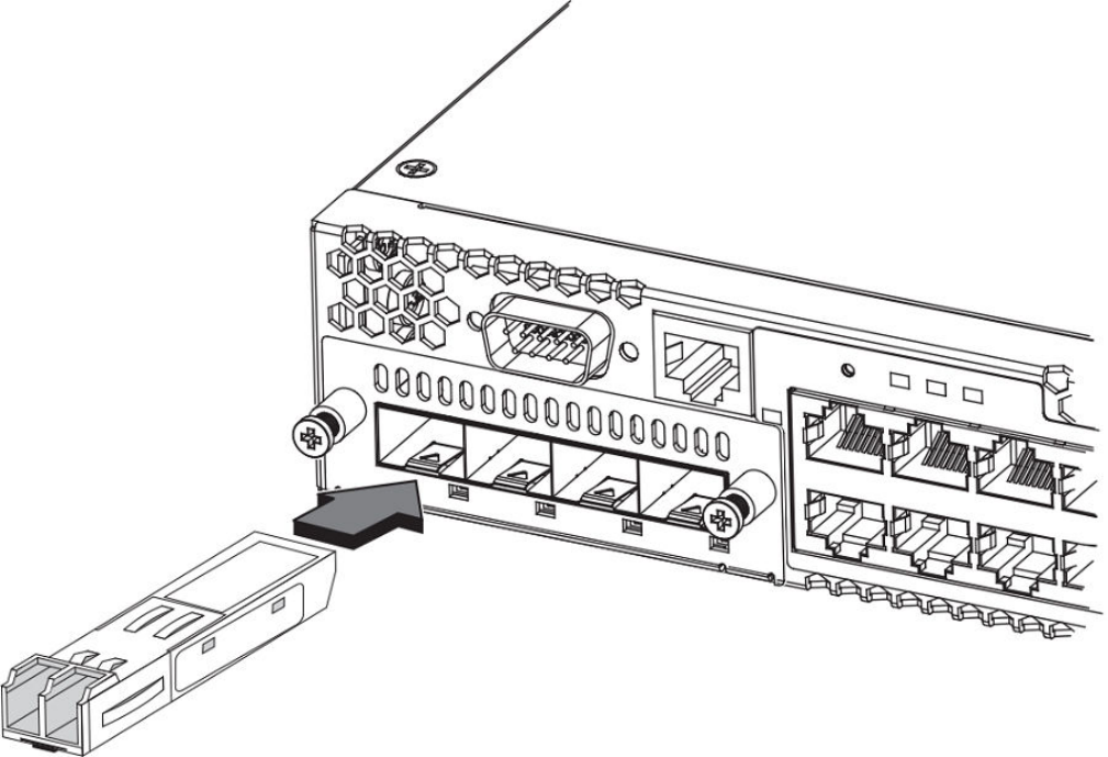
FIGURE 46 Installing a transceiver into Brocade FCX 624-E, FCX 624-I, FCX 648-E, and FCX 648-I devices
Cabling a ber-optic transceiver
Use the following steps to cable a ber-optic transceiver.
1. Remove the protective covering from the ber-optic port connectors and store the covering for future use.
2. Before cabling a ber-optic transceiver, Brocade strongly recommends cleaning the cable connectors and the port connectors.
For more information, refer to Cleaning the ber-optic connectors on page 71.
3. Gently insert the cable connector (a tab on each connector should face upward) into the transceiver connector until the tabs lock
into place.
4. Observe the link and active LEDs to determine if the network connections are functioning properly. For more information about
the LED indicators, refer to Observing LEDs on page 72.
Cleaning the ber-optic connectors
To avoid problems with the connection between the ber optic transceiver (SFP, SFP+, or mini-GBIC) and the ber cable connectors,
Brocade strongly recommends cleaning both connectors each time you disconnect and reconnect them. Dust can accumulate in the
connectors and cause problems such as reducing the optic launch power.
Conguring IP addresses
Brocade FCX Series Hardware Installation Guide
Part Number: 53-1003616-03 71

To clean the ber cable connectors, Brocade recommends using a ber optic reel-type cleaner. You can purchase this type of cleaner
from the following website:
http://www.sber.com/Home_Page.asp
When not using an SFP connector, make sure to keep the protective covering in place.
Testing connectivity
Test for connectivity by observing the LEDs related to network connection.
Pinging an IP address
To verify that a FastIron CX device can reach another device through the network, enter a command similar to the following at any level of
the CLI.
device> ping 10.33.4.7
Syntax: ping ip-addr [ source ip-addr ] [ countnum ] [ timeout msec ] [ ttl num ] [ verify ] [ no-fragment ] [ quiet ] [ data 1-to-4-byte-
hex# ] [ numeric ] [ size byte ] [ brief [ max-print-per-sec num-0-2047 ] ]
NOTE
If you address the ping to the IP broadcast address, the device lists the rst four
responses.
Observing LEDs
After you install the network cables, you can observe certain LEDs to determine if the network connections are functioning properly. The
following table outlines the LEDs related to the network connections, the desired state of each LED, possible abnormal states of each
LED, and what to do if an LED indicates an abnormal state.
TABLE 24 Network connection-related LED states
LED Desired State Meaning Abnormal State Meaning or Action
Ethernet(1-24/48)
Link or Activity or Speed
On or Blinking (Green or
Amber)
A link is established with the
remote port and user
packets are being
transmitted or received.
O A link is not established with
the remote port. You can do
the following:
• Verify that the
connection to the
other network
device has been
properly made.
Also, make
certain that the
other network
device is powered
on and operating
correctly.
• Verify that the
port has not been
disabled through
a conguration
change. You can
use the CLI. If
Testing connectivity
Brocade FCX Series Hardware Installation Guide
72 Part Number: 53-1003616-03

TABLE 24 Network connection-related LED states (continued)
LED Desired State Meaning Abnormal State Meaning or Action
you have
congured an IP
address on the
device, you also
can use the
Brocade Network
Advisor.
• For the
combination
ports (ports 1–4),
check that the
shared SFP port
(1F–4F) is not
being used.
• If the other
actions don’t
resolve the
problem, try
using a dierent
port or a dierent
cable.
HPOE
(1-24/48)
NOTE
Note: FCX-E
and FCX-I
devices do not
support HPOE
On Green The port is providing HPOE
power.
O A link is not established with
the HPOE device. You can
do the following:
• Verify that the
connection to the
other network
device has been
properly made.
• If the other
actions don’t
resolve the
problem, try
using a dierent
port or a dierent
cable.
SFP(1F–4F)
Link or Activity
On Green A link is established with the
remote port.
O A link is not established with
the remote port. You can do
the following:
• Verify that the
connection to the
other network
device has been
properly made.
Also, make
certain that the
other network
device is powered
on and operating
correctly.
• Verify that the
transmit port on
the Brocade
device is
connected to the
receive port on
the other network
Testing connectivity
Brocade FCX Series Hardware Installation Guide
Part Number: 53-1003616-03 73

TABLE 24 Network connection-related LED states (continued)
LED Desired State Meaning Abnormal State Meaning or Action
device, and that
the receive port
on the Brocade
device is
connected to the
transmit port on
the other network
device. If you are
not certain,
remove the two
cable connectors
from the port
connector and
reinsert them in
the port
connector,
reversing their
order.
• Dust may have
accumulated in
the cable
connector or port
connector. For
information about
cleaning the
connectors, refer
to Cleaning the
ber-optic
connectors on
page 71.
• Verify that the
port has not been
disabled through
a conguration
change.
• Check that the
conguration has
not forced the
use of the RJ45
port shared with
the SFP port.
• If the other
actions don’t
resolve the
problem, try
using a dierent
port or a dierent
cable.
SFP(1F–4F)
Speed
On (Green or Amber) A link is established with the
remote port.
O A link is not established with
the remote port. You can do
the following:
• Check the Link
LED to make
sure the link is still
established with
the remote port. If
not, take the
actions described
Testing connectivity
Brocade FCX Series Hardware Installation Guide
74 Part Number: 53-1003616-03

TABLE 24 Network connection-related LED states (continued)
LED Desired State Meaning Abnormal State Meaning or Action
in the Meaning or
Action column for
the Link LED.
SFP+(1F–4F)
Link or Activity
On Green A link is established with the
remote port.
O A link is not established with
the remote port. You can do
the following:
• Verify that the
connection to the
other network
device has been
properly made.
Also, make
certain that the
other network
device is powered
on and operating
correctly.
• Verify that the
transmit port on
the Brocade
device is
connected to the
receive port on
the other network
device, and that
the receive port
on the Brocade
device is
connected to the
transmit port on
the other network
device. If you are
not certain,
remove the two
cable connectors
from the port
connector and
reinsert them in
the port
connector,
reversing their
order.
• Dust may have
accumulated in
the cable
connector or port
connector. For
information about
cleaning the
connectors, refer
to Cleaning the
ber-optic
connectors on
page 71.
• Verify that the
port has not been
disabled through
Testing connectivity
Brocade FCX Series Hardware Installation Guide
Part Number: 53-1003616-03 75

TABLE 24 Network connection-related LED states (continued)
LED Desired State Meaning Abnormal State Meaning or Action
a conguration
change.
• Check that the
conguration has
not forced the
use of the RJ45
port shared with
the SFP port.
• If the other
actions don’t
resolve the
problem, try
using a dierent
port or a dierent
cable.
SFP+(1F–4F)
Speed
On (Green or Amber) A link is established with the
remote port.
O A link is not established with
the remote port. You can do
the following:
• Check the Link
LED to make
sure the link is still
established with
the remote port. If
not, take the
actions described
in the Meaning or
Action column for
the Link LED.
If a problem persists after taking these actions, contact Brocade Technical Support.
Tracing a route
To determine the path through which a Brocade device can reach another device, enter a command similar to the following at any level of
the CLI on the device.
device> traceroute 10.33.4.7
Syntax: traceroute host-ip-addr [ maxttlvalue ] [ minttl value ] [ numeric ] [ timeout value ] [ source-ip ip-addr ]
The CLI displays trace route information for each hop as soon as the information is received. Traceroute requests display all responses to
a given TTL. In addition, if there are multiple equal-cost routes to the destination, the Brocade device displays up to two responses by
default.
Troubleshooting network connections
• For the indicated port, verify that both ends of the cabling (at the device and the connected device) are snug.
• Verify that the device and the connected device are both powered on and operating correctly.
• Verify that you have used the correct cable type for the connection:
– For twisted-pair connections to an end node, use straight-through cabling.
Troubleshooting network connections
Brocade FCX Series Hardware Installation Guide
76 Part Number: 53-1003616-03
– For ber optic connections, verify that the transmit port on the device is connected to the receive port on the connected
device, and that the receive port on the device is connected to the transmit port on the connected device.
• Use the CLI to verify that the port has not been disabled through a conguration change. If you have congured an IP address
on the device, you also can use the Brocade Network Advisor.
• If the other procedures don’t resolve the problem, try using a dierent port or a dierent cable.
Digital optical monitoring
You can congure your device to monitor optical transceivers in the system, either globally or by specied port. When this feature is
enabled, the system monitors the temperature and signal power levels for the optical transceivers in the specied ports. Console
messages and syslog messages are sent when optical operating conditions fall below or rise above the XFP, SFP, and SFP+
manufacturer’s recommended thresholds. For more information about digital optical monitoring, refer to FastIron Ethernet Switch
Administration Guide.
Virtual cable testing
Most FastIron devices support Virtual Cable Test (VCT) technology. VCT technology enables the diagnosis of a conductor (wire or cable)
by sending a pulsed signal into the conductor, then examining the reection of that pulse. This method of cable analysis is referred to as
Time Domain Reectometry (TDR). By examining the reection, the Brocade device can detect and report cable statistics such as local
and remote link pair, cable length, and link status.
Virtual Cable Testing conguration notes
• VCT is supported on copper ports only. It is not supported on ber ports.
• VCT is only supported when Ethernet port speed is congured to Auto. VCT does not work on ports with xed speeds.
• VCT is not supported on the following:
– ICX 6610-24F
– SX-FI24GPP
– SX-FI48GPP
– SX-FI2XG
– SX-FI8XG
– SX-FI24HF
• The port to which the cable is connected must be enabled when you issue the command to diagnose the cable. If the port is
disabled, the command is rejected.
• If the port is operating at 100 Mbps half-duplex, the TDR test on one pair will fail.
• If the remote pair is set to forced 100 Mbps, any change in MDI/MDIX may cause the device to interpret the Multilevel
Threshold-3 (MLT-3) as a reected pulse, in which case, the device will report a faulty condition. In this scenario, it is
recommended that you run the TDR test a few times, clearing the registers before each test, for accurate results.
Virtual Cable Test command syntax
To diagnose a cable using TDR, enter commands such as the following at the Privileged EXEC level of the CLI.
device# phy cable-diagnostics tdr 1/1/1
The clear-diag tdr command clears results of any previous TDR test from test registers for port 1/1/1 (port 1 on slot 1 on device 1).
Troubleshooting network connections
Brocade FCX Series Hardware Installation Guide
Part Number: 53-1003616-03 77

NOTE
It is recommended that you clear the TDR test registers before each test.
device# clear cable-diagnostics tdr 1/1/1
The command in the previous example diagnoses the cable attached to port 1/1/1.
When you issue the phy cable-diagnostics command, the command brings the port down for a second or two, and then immediately
brings the port back up.
Syntax: clear cable-diagnostics tdr stackid/slot/port
Syntax: phy cable-diagnostics tdr stackid/slot/port
Viewing the results of the cable analysis
To display the results of the cable analysis, enter a command such as the one shown in the following examples at the Privileged EXEC
level of the CLI.
In the rst example, the command displays TDR test results for port 1, slot 1 on device 1 in the stack. The results indicate that the port is
down or the cable is not connected.
device>show cable-diagnostics tdr 1/1/1
Port Speed Local pair Pair Length Remote pair Pair status
--------- ----- ---------- ----------- ----------- -----------
-- ----- ------- ----- ------ ----------
01 UNKWN Pair A <=3 M Open
Pair B <=3 M Open
Pair C <=3 M Open
Pair D <=3 M Open
In the second test example, the TDR test results for the same port show details for an active port.
device>show cable-diagnostics tdr 1/1/1
Port Speed Local pair Pair Length Remote pair Pair status
--------- ----- ---------- ----------- ----------- -----------
01 1000M Pair A <50M Pair B Terminated
Pair B <50M Pair A Terminated
Pair C <50M Pair D Terminated
Pair D <50M Pair C Terminated
Syntax: show cable-diagnostics tdr stackid/slot/port
In the output shown, "Local pair" indicates the assignment of wire pairs from left to right, where Pair A is the left-most pair. The following
table shows the "Local pair" mapping to the T568A pin/pair and color assignment from the TIA/EIA-568-B standard.
TABLE 25 Local pair denition
Local pair T568A pair and color assignment
Pair A Pair 3 (green)
Pair B Pair 2 (orange)
Pair C Pair 1 (blue)
Pair D Pair 4 (brown)
The following gure illustrates the T568A pin/pair assignment.
Troubleshooting network connections
Brocade FCX Series Hardware Installation Guide
78 Part Number: 53-1003616-03
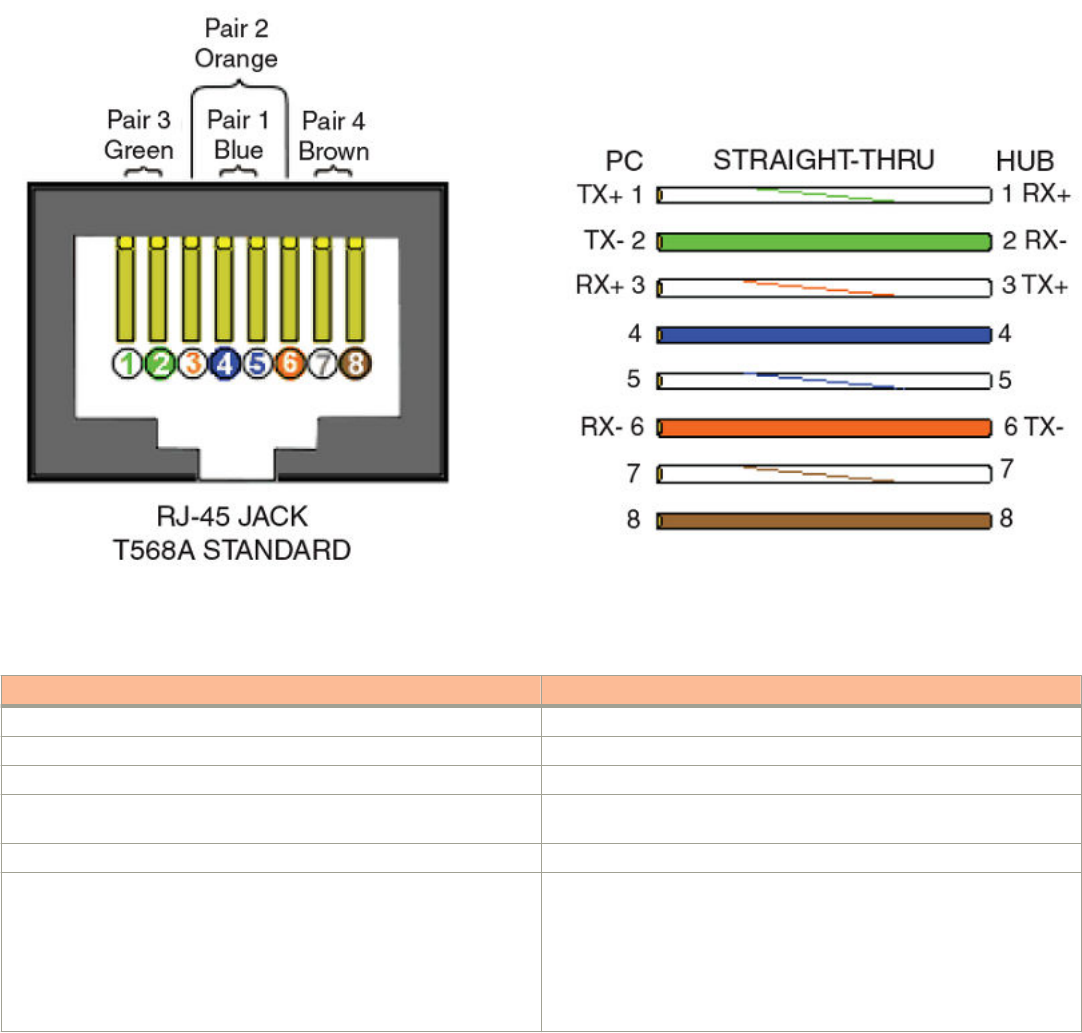
FIGURE 47 T568A pin/pair assignment
The following table describes the elds shown in the show cable-diagnostics port command output.
TABLE 26 Cable statistics
Field Meaning
Port The port that was tested.
Speed The port current line speed.
Local pair The local link name. Refer to the previous local pair denition table.
Pair Length The cable length when terminated, or the distance to the point of fault
when the line is not up.
Remote pair The remote link name.
Pair status The status of the link. This eld displays one of the following:
• Terminated: The link is up.
• Shorted: A short is detected in the cable.
• Open: An opening is detected in the cable.
• ImpedMis: The impedance is mismatched.
• Failed: The TDR test failed.
Troubleshooting network connections
Brocade FCX Series Hardware Installation Guide
Part Number: 53-1003616-03 79
Brocade FCX Series Hardware Installation Guide
80 Part Number: 53-1003616-03

Managing the FCX Hardware
• Managing temperature settings...................................................................................................................................................................81
• Displaying FCX CPU usage..........................................................................................................................................................................85
• Hardware maintenance schedule................................................................................................................................................................85
• Replacing a copper or ber optic module............................................................................................................................................... 85
DANGER
The procedures in this manual are for qualied service personnel.
Managing temperature settings
This section describes how to display temperature settings on the device and how to change the temperature warning and shutdown
levels.
Using the temperature sensor
The device ships with three built-in temperature sensors that cause the device to generate a Syslog message and SNMP trap if the
temperature exceeds a specied warning level or shutdown level. If the device temperature exceeds the safe threshold (shutdown level),
the device will reboot.
The software reads the temperature sensors based on the device poll time, which is by default 60 seconds. If the temperature equals or
exceeds the shutdown temperature for ve consecutive polls by the software, the software will reboot the device to prevent damage.
You can use the CLI to perform the following tasks:
• Display the temperature of the device
• Change the warning and shutdown temperature levels
• Change the device poll time
Displaying the temperature
By default, the software polls the temperature sensor every 60 seconds to get the current temperature. This poll rate is controlled by the
device poll time, which also controls how often the software polls other system components.
To display the temperature of a device, enter the show chassis command at any level of the CLI.
device# show chassis
The stack unit 1 chassis info:
Power supply 1 (NA - AC - Regular) present, status ok
Power supply 2 not present
Fan ok, speed (auto): [[1]]<->2<->3
Fan speed switching temperature thresholds:
1 -> 2 @ 61 deg-C
1 <- 2 @ 56 deg-C
2 -> 3 @ 67 deg-C
2 <- 3 @ 62 deg-C
MAC 1 Temperature Readings:
Current temperature : 58.5 deg-C
CPU Temperature Readings:
Current temperature : 52.0 deg-C
Warning level.......: 75.0 deg-C
Shutdown level......: 90.0 deg-C
Brocade FCX Series Hardware Installation Guide
Part Number: 53-1003616-03 81
Boot Prom MAC : 0000.0000.0720
Management MAC: 0000.0000.0720
Syntax: show chassis
Displaying Syslog messages for temperature
The software sends a Syslog message and an SNMP trap if the temperature crosses the warning or shutdown thresholds. The following
methods describe how to view the system log on the device. If you have congured the device to use a Syslog server or SNMP trap
receiver, see the documentation for the server or receiver.
To display the system log, enter the show log command at any CLI level.
device# show log
Syslog logging: enabled (0 messages dropped, 0 flushes, 0 overruns)
Buffer logging: level ACDMEINW, 8 messages logged
level code: A=alert C=critical D=debugging M=emergency E=error
I=informational N=notification W=warning
Static Log Buffer:
Dynamic Log Buffer (50 entries):
at 0 days 0 hours 2 minutes 0 seconds, level alert
Temperature 48.0 C degrees, warning level 45.0 C degrees, shutdown level 55.0 C degrees
at 0 days 0 hours 1 minutes 0 seconds, level alert
Temperature 40.0 C degrees, warning level 35.0 C degrees, shutdown level 45.0 C degrees
Changing temperature warning and shutdown levels
The default warning temperatures and the default shutdown temperatures for the device are:
- Warning temperature is 85 Deg-C (measured on mainboard)
- Shutdown temperature is 90 Deg-C (measured on mainboard)
NOTE
These temperatures reect the temperature of the board inside the
device.
To change the temperature at which the device sends a warning, enter a command similar to the following at the Privileged EXEC level of
the CLI:
device# temperature warning 1 85
Syntax: temperature warning stack-id value
The stack-id can be 1 - 8.
The value can be 0 - 125
device# temperature
temperature temperature sensor commands
device# temperature warning
warning Temperature at which the module sends a warning
device# temperature warning
DECIMAL Stack Number
device# temperature warning 1 87
device# show chassis
The stack unit 1 chassis info:
Power supply 1 (NA - AC - Regular) present, status ok
Power supply 2 not present
Fan ok, speed (auto): [[1]]<->2<->3
Fan speed switching temperature thresholds:
1 -> 2 @ 61 deg-C
1 <- 2 @ 56 deg-C
2 -> 3 @ 67 deg-C
Managing temperature settings
Brocade FCX Series Hardware Installation Guide
82 Part Number: 53-1003616-03
2 <- 3 @ 62 deg-C
MAC 1 Temperature Readings:
Current temperature : 58.5 deg-C
CPU Temperature Readings:
Current temperature : 52.0 deg-C
Warning level.......: 75.0 deg-C
Shutdown level......: 90.0 deg-C
Boot Prom MAC : 0000.0000.0720
Management MAC: 0000.0000.0720
Changing the shutdown temperature
You can change the shutdown temperature using the fan-threshold command as shown. The valid range is 0-125 deg-C.
device(config)# stack unit 1
device(config)# fan-threshold mp speed-3 62 95
device(config)# show chassis
The stack unit 1 chassis info:
Power supply 1 (NA - AC - Regular) present, status ok
Power supply 2 not present
Fan ok, speed (auto): [[1]]<->2<->3
Fan speed switching temperature thresholds:
1 -> 2 @ 61 deg-C
1 <- 2 @ 56 deg-C
2 -> 3 @ 67 deg-C
2 <- 3 @ 62 deg-C
MAC 1 Temperature Readings:
Current temperature : 58.5 deg-C
CPU Temperature Readings:
Current temperature : 52.0 deg-C
Warning level.......: 75.0 deg-C
Shutdown level......: 90.0 deg-C
Boot Prom MAC : 0000.0000.0720
Management MAC: 0000.0000.0720
Syntax: fan-threshold mp speed-3 lowest-value highest-value
The device will automatically reset and reload the software when the internal temperature reaches or exceeds the congured shutdown
level for ve minutes. The system is also capable of registering negative temperature settings.
To change the temperature at which the FastIron CX sends a warning, you must change the fan speed threshold. To view the current
temperature thresholds, enter the show chassis command:
device# show chassis
The stack unit 1 chassis info:
Power supply 1 (NA - AC - Regular) present, status ok
Power supply 2 not present
Fan ok, speed (auto): [[1]]<->2<->3
Fan speed switching temperature thresholds:
1 -> 2 @ 61 deg-C
1 <- 2 @ 56 deg-C
2 -> 3 @ 67 deg-C
2 <- 3 @ 62 deg-C
MAC 1 Temperature Readings:
Current temperature : 58.5 deg-C
CPU Temperature Readings:
Current temperature : 52.0 deg-C
Warning level.......: 75.0 deg-C
Shutdown level......: 90.0 deg-C
Boot Prom MAC : 0000.0000.0720
Management MAC: 0000.0000.0720
Enter a command to the following to change the temperature shutdown level from 80 deg-C to 90 deg-C.
device# stack unit 1
device(config-unit-1)# fan-threshold mp speed-3 50 90
Syntax: fan-threshold mp speed-3 lowest-value highest-value
Managing temperature settings
Brocade FCX Series Hardware Installation Guide
Part Number: 53-1003616-03 83
The value can be 0 - 125.
Enter the show chassis command to conrm the change:
device# show chassis
The stack unit 1 chassis info:
Power supply 1 (NA - AC - Regular) present, status ok
Power supply 2 not present
Fan ok, speed (auto): [[1]]<->2<->3
Fan speed switching temperature thresholds:
1 -> 2 @ 61 deg-C
1 <- 2 @ 56 deg-C
2 -> 3 @ 67 deg-C
2 <- 3 @ 62 deg-C
MAC 1 Temperature Readings:
Current temperature : 58.5 deg-C
CPU Temperature Readings:
Current temperature : 52.0 deg-C
Warning level.......: 75.0 deg-C
Shutdown level
......: 90.0 deg-C
Boot Prom MAC : 0000.0000.0720
Management MAC: 0000.0000.0720
Changing the temperature polling interval
The software reads the temperature sensor and polls other hardware sensors according to the value set for the poll time, which is 60
seconds by default. You can change the poll time using the CLI.
To change the poll time, enter a command similar to the following at the global CONFIG level:
device(config)# chassis poll-time 200
Syntax: chassis poll-time value
The value parameter is in seconds. It can be 0 - 65535.
Removing MAC address entries
You can remove the following types of learned MAC address entries from the system MAC address table:
• All MAC address entries
• All MAC address entries for a specied Ethernet port
• All MAC address entries for a specied VLAN
• A specied MAC address entry in all VLANs
For example, to remove entries for the MAC address 00-00-00 in all VLANs, enter the following command at the Privileged EXEC level
of the CLI:
device# clear mac-address 00-00-00
Syntax: clear mac-address { mac-address | ethernet port-num | vlan number }
If you enter the clear mac-address command without any parameters, the software removes all MAC entries.
Use the mac-address parameter to remove a specied MAC address from all VLANs. Specify the MAC address in the following format:
HHHH.HHHH.HHHH.
Use the ethernet port-num parameter to remove all MAC addresses for a specied Ethernet port.
Use the vlan number parameter to remove all MAC addresses for a specied VLAN.
Managing temperature settings
Brocade FCX Series Hardware Installation Guide
84 Part Number: 53-1003616-03

Displaying FCX CPU usage
You can display the amount of the FCX CPU in use. To do so, enter the show cpu command at any level of the CLI:
device# show cpu
31 percent busy, from 3248 sec ago
1 sec avg: 10 percent busy
5 sec avg: 10 percent busy
60 sec avg: 10 percent busy
300 sec avg: 10 percent busy
Syntax: show cpu
Hardware maintenance schedule
FCX switch hardware components require minimal maintenance. Brocade recommends cleaning the ber-optic connectors on a ber-
optic port and the connected ber cable each time you disconnect the cable.
You can replace the copper and ber optic modules (SFPs or mini-GBICs).
Replacing a copper or ber optic module
You can remove an SFP from a slot and replace it with a new one while the FastIron CX is powered on and running.
This section provides information about the following tasks:
• Removing a copper or ber optic module
• Installing a new copper or ber optic module
• Cabling a ber optic module
Removing a copper or ber optic module
You can remove a copper or ber SFP (also called a mini-GBIC) from a slot while the FastIron CX is powered on and running.
While removing a copper or ber optic module, be sure to wear an ESD wrist strap with a plug for connection to the ESD connector on
the FastIron CX.
DANGER
For safety reasons, the ESD wrist strap should contain a series 1 megaohm resistor.
To remove a copper or ber optic module from an SFP slot, do the following.
1. Put on the ESD wrist strap and ground yourself by attaching the clip end to a metal surface (such as an equipment rack).
2. Disconnect the copper or ber cable connector from the port connector.
Replacing a copper or ber optic module
Brocade FCX Series Hardware Installation Guide
Part Number: 53-1003616-03 85
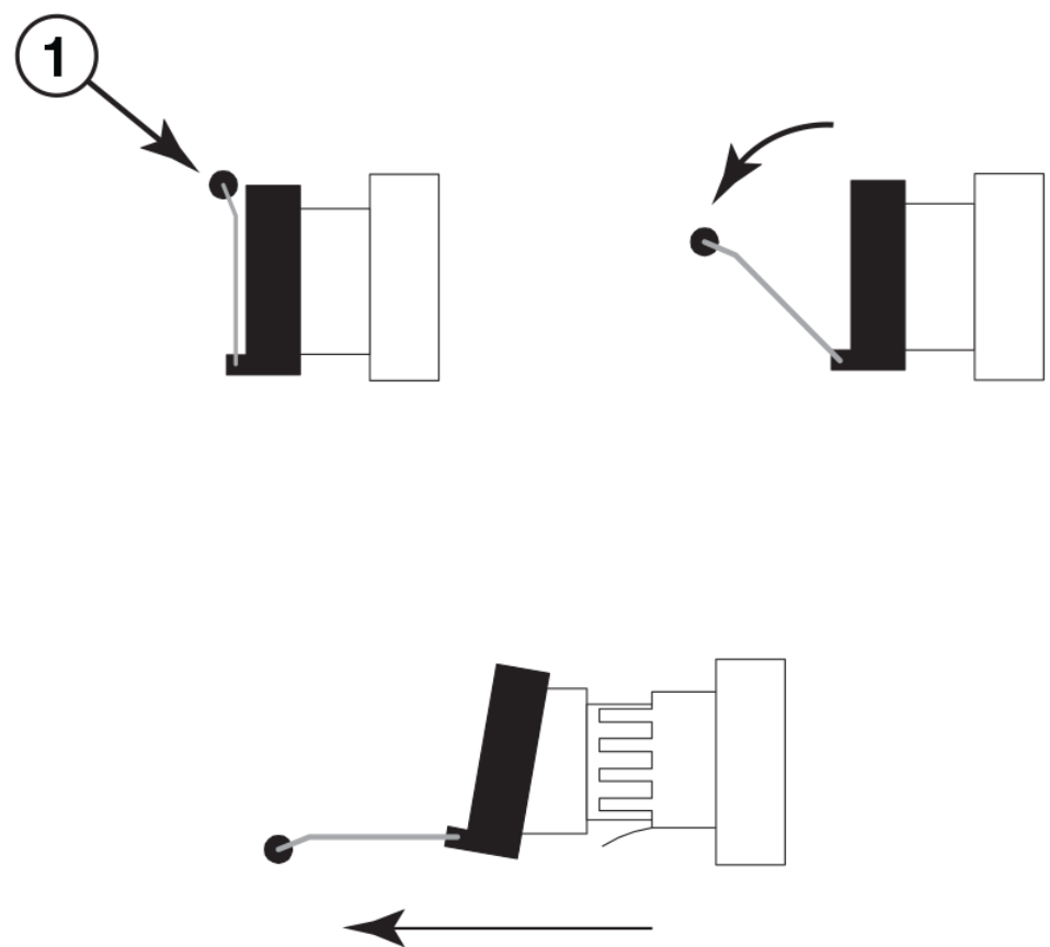
3. Unlock the copper or ber optic module by pulling the bail latch forward, away from the front panel of the module.
On 1000BaseSX ports, the bail latch is enclosed in a black sleeve, and on 1000BaseLX ports, the bail latch is enclosed in a
blue sleeve.
FIGURE 48 Unlocking the bail latch
1. Bail Latch
NOTE
The bail latch may be attached to either the top or the bottom of the mini-GBIC.
4. Grasp the bail latch and pull the copper or ber optic module out of the port.
FIGURE 49 Remove ber optic module
5. Store the copper or ber optic module in a safe, static-free place or in an anti-static bag.
6. Install a new copper or ber optic module in the port.
Cabling a ber optic module
For instructions on cabling a ber optic module refer to Cabling a ber-optic transceiver on page 71.
Replacing a copper or ber optic module
Brocade FCX Series Hardware Installation Guide
86 Part Number: 53-1003616-03
Brocade FCX Series Hardware Installation Guide
88 Part Number: 53-1003616-03

Brocade FCX Series Technical
Specications
This document highlights the features and specications for the Brocade FCX Series switches.
System specications
System component Description
Enclosure 1U, 19-inch EIA-compliant, power from non-port side
Power inlet C14
Power supplies Up to two internal, redundant, eld-replaceable, load-sharing AC power supplies
Fans Single removable fan unit
Cooling Brocade FCX 624 and FCX 648: front-to-back airow (reversible)
Brocade FCX 624S, FCX 624S-F, FCX 648S, FCX 624S-HPOE, and FCX 648S-HPOE: side-to-back airow
System architecture Stackable Layer 2/3 edge switches with 24 or 48 GbE ports and optional 10 GbE uplink ports
Ethernet
System component Description
10/100/1000 Mbps RJ-45 ports FCX 624, FCX 624S, and FCX 624S-HPOE: 24
FCX 648, FCX 648S, FCX 648S-HPOE: 48
100/1000 Mbps SFP ports FCX 624S-F: 20
1000 Mbps combo ports FCX 624 and FCX 648: 4 (optional)
FCX 624S, FCX 648S, FCX 624S-HPOE, and FCX 648S-HPOE: 4
10 Gigabit Ethernet ports FCX 624 and FCX 648: 4 SFP+ (optional)
FCX 624S, FCX 648S, FCX 624S-HPOE, and FCX 648S-HPOE: 2 SFP+ or 2 XFP (optional)
Maximum PoE Class 3 ports FCX 624S-HPOE: 24 (two power supplies)
FCX 648S-HPOE: 48 (two power supplies)
Maximum PoE+ ports FCX 624S-HPOE: 24 (two power supplies)
FCX 648S-HPOE: 26 (two power supplies)
Ethernet management port Out-of-band Ethernet management: 10/100/1000 Mbps RJ-45 (xed)
LEDs
System component Description
Port status Ethernet
HPOE
Brocade FCX Series Hardware Installation Guide
Part Number: 53-1003616-03 89

System component Description
NOTE
FCX-E and FCX-I devices do not support HPOE.
System status Power suppy
Diag
Out-of-band management
A or S (Active or Standby)
Up Link or Down Link
Stack ID
Power status AC OK
DC OK
Other
System component Description
Serial cable EIA or TIA DB-9 serial cable (M or F)
RJ-45 to DB9 adapter Console management
RJ-45 connector 10/100/1000 Mbps
Weight and physical dimensions
Model Height Width Depth Weight
Brocade FCX 624S,
Brocade FCX 648S,
Brocade FCX 624S-F
4.40 cm
1.70 in
44.00 cm
17.32 in
38.60 cm
15.19 in
4.00 kg
8.80 lbs
Brocade FCX 624S-
HPOE, Brocade FCX
648S-HPOE
4.40 cm
1.70 in
44.00 cm
17.32 in
44.00 cm
17.32 in
4.50 kg
9.90 lbs
Brocade FCX 624-E,
Brocade FCX 624-I
4.40 cm
1.70 in
44.00 cm
17.32 in
43.50 cm
17.13 in
5.35 kg
11.79 lbs
Brocade FCX 648-E,
Brocade FCX 648-I
4.40 cm
1.70 in
44.00 cm
17.32 in
43.50 cm
17.13 in
5.71 kg
12.59 lbs
Environmental requirements
Condition Operational Non-operational
Ambient temperature 32°F to 104°F
0°C to 40°C
−25°C to 70°C (−23°F to 158°F)
Relative humidity (non-
condensing)
5% to 95% 95%
Other
Brocade FCX Series Hardware Installation Guide
90 Part Number: 53-1003616-03

Condition Operational Non-operational
Altitude (above sea level) 0 - 10000 feet (3000 m) 3,000 m (10,000 feet)
Airow Brocade FCX 624S, FCX 648S, FCX 624S-F, FCX
624S-HPOE, and FCX 648S-HPOE: right to left: 58.27
cmh (34.3 cfm)
Brocade FCX 624-E and FCX 648-E: front to rear:
144.75 cmh (85.2 cfm)
Brocade FCX 624-I and FCX 648-I: rear to front: 144.75
cmh (85.2 cfm)
N/A
Heat dissipation Brocade FCX 624: 312.8 BTU/hr
Brocade FCX 648: 421.6 BTU/hr
Brocade FCX 624S: 319 BTU/hr
Brocade FCX 624S-F: 348 BTU/hr
Brocade FCX 648S: 416 BTU/hr
Brocade FCX 624S-HPOE: 365 BTU/hr
Brocade FCX 648S-HPOE: 570 BTU/hr
N/A
Operating noise Brocade FCX 624S, FCX 648S, FCX 624S-F, FCX
624S-HPOE, and FCX 648S-HPOE: ideal 51 dBA
Brocade FCX 624-E, FCX 624-I, FCX 648-E, and FCX
648-I: ideal 60 dBA
N/A
Power supply specications (per PSU)
Power supply
model
Maximum output
power rating (DC)
Input voltage Input line
frequency
Maximum input
current
Input line
protection
Maximum inrush
current
RPS13
RPS13-I
210 W 100 - 240 VAC 50/60 Hz
(nominal)
47-63 Hz (range)
1.2 - 2.8 A Line & Neutral < 75 Amps peak
maximum
RPS14 620 W 100 - 240 VAC 50/60 Hz
(nominal)
47-63 Hz (range)
3.3 - 7.8 A Line & Neutral < 75 Amps peak
maximum
Power consumption (maximum conguration)
NOTE
The FCX devices do not support a DC power supply.
Model name @100 VAC input @200 VAC input @-48 VDC input Minimum number of
power supplies
Notes
FCX 624 0.9 A
92 W
0.6 A N/A 1 With 4-port 10 GbE
module installed and
one power supply.
FCX 648 1.2 A
112 W
0.7 A N/A 1 With 4-port 10 GbE
module installed and
one power supply.
Power consumption (maximum conguration)
Brocade FCX Series Hardware Installation Guide
Part Number: 53-1003616-03 91

Model name @100 VAC input @200 VAC input @-48 VDC input Minimum number of
power supplies
Notes
FCX 624S 1.09 A
94 W
0.51 A N/A 1
FCX 624S-F 1.00 A
102.1 W
0.58 A N/A 1
FCX 648S 1.39 A
122 W
0.63 A N/A 1
FCX 624S-HPOE 1.09 A
509 W
0.58 A N/A 1 Full PoE power
requires two power
supplies installed.
FCX 648S-HPOE 1.72 A
970 W
0.94 A N/A 1 Full PoE power
requires two power
supplies installed.
Data port specications (Ethernet)
Model Port type Number of
ports
Description
FCX 624 RJ-45 ports 24 Supports maximum 24 10/100/1000 Mbps RJ-45 ports per system.
Combo ports 4 (optional) Supports maximum four 1000 Mbps combo ports per system.
Ethernet ports 4 SFP+
(optional)
Supports maximum four SFP+ 10 Gigabit Ethernet ports per system.
FCX 648 RJ-45 ports 48 Supports maximum 48 10/100/1000 Mbps RJ-45 ports per system.
Combo ports 4 (optional) Supports maximum four 1000 Mbps combo ports per system.
Ethernet ports 4 SFP+
(optional)
Supports maximum four SFP+ 10 Gigabit Ethernet ports per system.
FCX 624S RJ-45 ports 24 Supports maximum 24 10/100/1000 Mbps RJ-45 ports per system.
Combo ports 4 Supports maximum four 1000 Mbps combo ports per system.
Ethernet ports 2 SFP+ or 2
XFP (optional)
Supports maximum two SFP+ or two XFP 10 Gigabit Ethernet ports per system.
16 Gbps CX4
stacking ports
2 Supports maximum two 16 Gbps CX4 stacking ports per system.
FCX 648S RJ-45 ports 48 Supports maximum 48 10/100/1000 Mbps RJ-45 ports per system.
Combo ports 4 Supports maximum four 1000 Mbps combo ports per system.
Ethernet ports 2 SFP+ or 2
XFP (optional)
Supports maximum two SFP+ or two XFP 10 Gigabit Ethernet ports per system.
16 Gbps CX4
stacking ports
2 Supports maximum two 16 Gbps CX4 stacking ports per system.
FCX 624S-F RJ-45 ports N/A
SFP ports 20 Supports maximum 20 100/1000 Mbps SFP ports.
Combo ports 4 Supports maximum four 1000 Mbps combo ports per system.
Ethernet ports 2 SFP+ or 2
XFP (optional)
Supports maximum two SFP+ or two XFP 10 Gigabit Ethernet ports per system.
16 Gbps CX4
stacking ports
2 Supports maximum two 16 Gbps CX4 stacking ports per system.
Data port specications (Ethernet)
Brocade FCX Series Hardware Installation Guide
92 Part Number: 53-1003616-03

Model Port type Number of
ports
Description
FCX 624S-HPOE RJ-45 ports 24 Supports maximum 24 10/100/1000 Mbps RJ-45 ports per system.
Combo ports 4 Supports maximum four 1000 Mbps combo ports per system.
Ethernet ports 2 SFP+ or 2
XFP (optional)
Supports maximum two SFP+ or two XFP 10 Gigabit Ethernet ports per system.
16 Gbps CX4
stacking ports
2 Supports maximum two 16 Gbps CX4 stacking ports per system.
Maximum PoE
Class 3 ports
24 Supports maximum 24 PoE Class 3 ports per system.
Maximum PoE+
ports
24 (two power
supplies)
Supports maximum 24 PoE+ ports per system.
FCX 648S-HPOE RJ-45 ports 48 Supports maximum 48 10/100/1000 Mbps RJ-45 ports per system.
Combo ports 4 Supports maximum four 1000 Mbps combo ports per system.
Ethernet ports 2 SFP+ or 2
XFP (optional)
Supports maximum two SFP+ or two XFP 10 Gigabit Ethernet ports per system.
16 Gbps CX4
stacking ports
2 Supports maximum two 16 Gbps CX4 stacking ports per system.
Maximum PoE
Class 3 ports
48 (two power
supplies)
Supports maximum 48 PoE Class 3 ports per system.
Maximum PoE+
ports
26 (two power
supplies)
Supports maximum 26 PoE+ ports per system.
Serial port specications (DB9)
Pin Signal Description
1 Reserved Reserved
2 TXD (output) Transmit data
3 RXD (input) Receive data
4 Reserved Reserved
5 GND Logic ground
6 Reserved Reserved
7 Reserved Reserved
8 Reserved Reserved
9 Reserved Reserved
Serial port specications (pinout RJ-45)
Pin Signal Description
1 Not supported N/A
2 Not supported N/A
3 UART1_TXD Transmit data
4 GND Logic ground
5 GND Logic ground
Serial port specications (pinout RJ-45)
Brocade FCX Series Hardware Installation Guide
Part Number: 53-1003616-03 93

Pin Signal Description
6 UART1_RXD Receive data
7 Not supported N/A
8 Not supported N/A
Serial port specications (protocol)
Parameter Value
Baud 9600 bps
Data bits 8
Parity None
Stop bits 1
Flow control None
Regulatory compliance (EMC)
• FCC Part 15, Subpart B (Class A)
• EN 55022 (CE mark) (Class A)
• EN 55024 (CE mark) (Immunity) for Information Technology Equipment
• ICES-003 (Canada) (Class A)
• AS/NZ 55022 (Australia) (Class A)
• VCCI (Japan) (Class A)
• EN 61000-3-2
• EN 61000-3-3
• EN 61000-6-1
Regulatory compliance (safety)
• CAN/CSA-C22.2 No. 60950-1-07/UL60950-1 - Safety of Information Technology Equipment
• EN 60825-1 Safety of Laser Products - Part 1: Equipment Classication, Requirements and User's Guide
• EN 60825-2 Safety of Laser Products - Part 2: Safety of Optical Fibre Communications Systems
• EN 60950-1, IEC 60950-1 Safety of Information Technology Equipment
Regulatory compliance (environmental)
• 2011/65/EU - Restriction of the use of certain hazardous substance in electrical and electronic equipment (EU RoHS)
• 2012/19/EU - Waste electrical and electronic equipment (EU WEEE)
• 94/62/EC - packaging and packaging waste (EU)
• 2006/66/EC - batteries and accumulators and waste batteries and accumulators (EU battery directive)
Serial port specications (protocol)
Brocade FCX Series Hardware Installation Guide
94 Part Number: 53-1003616-03
• 1907/2006 of the European Parliament and of the Council of 18 December 2006 concerning the Registration, Evaluation,
Authorisation and Restriction of Chemicals (EU REACH)
• Section 1502 of the Dodd-Frank Wall Street Reform and Consumer Protection Act of 2010 - U.S. Conict Minerals
• 30/2011/TT-BCT - Vietnam circular
• SJ/T 11363-2006 Requirements for Concentration Limits for Certain Hazardous Substances in EIPs (China)
• SJ/T 11364-2006 Marking for the Control of Pollution Caused by EIPs (China)
Regulatory compliance (environmental)
Brocade FCX Series Hardware Installation Guide
Part Number: 53-1003616-03 95
Brocade FCX Series Hardware Installation Guide
96 Part Number: 53-1003616-03

Troubleshooting
• Diagnosing switch indicators .......................................................................................................................................................................97
Diagnosing switch indicators
TABLE 27 Troubleshooting chart
Symptom Action
Power LED is O • Internal power supply is disconnected.
• Check connections between the switch, the power cord, and the
wall outlet.
• Contact Technical Support.
Power LED is Amber Internal power supply has failed. Contact Technical Support.
Diag LED is Amber • The switch self test has detected a fault.
• Power cycle the switch to try and clear the condition. If the
condition persists, contact Technical Support.
Link LED is O • Verify that the switch and attached device are powered on.
• Be sure the cable is plugged into both the switch and
corresponding device.
• Verify that the proper cable type is used and its length does not
exceed specied limits.
• Check the adapter on the attached device and cable
connections for possible defects. Replace the defective adapter
or cable if necessary.
Power and cooling problems
If the power indicator does not turn on when the power cord is plugged in, you may have a problem with the power outlet, power cord, or
internal power supply. However, if the unit powers o after running for a while, check for loose power connections, power losses or surges
at the power outlet, and verify that the fans on the unit are unobstructed and running prior to shutdown. If you still cannot isolate the
problem, then the internal power supply may be defective. In this case, contact Technical Support for assistance.
Installation
Verify that all system components have been properly installed. If one or more components appear to be malfunctioning (such as the
power cord or network cabling), test them in an alternate environment where you are sure that all the other components are functioning
properly.
In-band access
You can access the management agent in the switch from anywhere within the attached network using Telnet, a Web browser, or other
network management software. However, you must rst congure the switch with a valid IP address, subnet mask, and default gateway. If
you have trouble establishing a link to the management agent, check to see if you have a valid network connection. Then verify that you
entered the correct IP address. Also, be sure the port through which you are connecting to the switch has not been disabled. If it has not
been disabled, then check the network cabling that runs between your remote location and the switch.
Brocade FCX Series Hardware Installation Guide
Part Number: 53-1003616-03 97
Brocade FCX Series Hardware Installation Guide
98 Part Number: 53-1003616-03

Regulatory Statements
• CE Statement......................................................................................................................................................................................................99
• China ROHS........................................................................................................................................................................................................99
• BSMI statement (Taiwan)................................................................................................................................................................................99
• Canadian requirements................................................................................................................................................................................100
• China CC statement.......................................................................................................................................................................................100
• Europe and Australia (CISPR 22 Class A Warning)......................................................................................................................... 101
• FCC warning (US only).................................................................................................................................................................................101
• Germany.............................................................................................................................................................................................................101
• KCC statement (Republic of Korea).........................................................................................................................................................101
• VCCI statement............................................................................................................................................................................................... 101
CE Statement
ATTENTION
This is a Class A product. In a domestic environment, this product might cause radio interference, and the user might be
required to take corrective measures.
The standards compliance label on this device contains the CE mark which indicates that this system conforms to the provisions of the
following European Council directives, laws, and standards:
• Electromagnetic Compatibility (EMC) Directive 2004/108/EEC
• Low Voltage Directive (LVD) 2006/95/EC
• EN50082-2/EN55024:1998 (European Immunity Requirements)
– EN61000-3-2/JEIDA (European and Japanese Harmonics Spec)
– EN61000-3-3
China ROHS
Refer to the latest revision of the China ROHS document (P/N 53‐1000428‐xx) which ships with the product.
BSMI statement (Taiwan)
Warning:
This is Class A product. In a domestic environment this product may cause radio interference in which case the user may be required to
take adequate measures.
Brocade FCX Series Hardware Installation Guide
Part Number: 53-1003616-03 99

Canadian requirements
This Class A digital apparatus meets all requirements of the Canadian Interference-Causing Equipment Regulations, ICES-003 Class A.
Cet appareil numérique de la classe A est conforme à la norme NMB-003 du Canada.
China CC statement
Canadian requirements
Brocade FCX Series Hardware Installation Guide
100 Part Number: 53-1003616-03

Europe and Australia (CISPR 22 Class A Warning)
This is a Class A product. In a domestic environment this product may cause radio interference in which case the user may be required to
take adequate measures.
FCC warning (US only)
This equipment has been tested and complies with the limits for a Class A computing device pursuant to Part 15 of the FCC Rules.
These limits are designed to provide reasonable protection against harmful interference when the equipment is operated in a commercial
environment.
This equipment generates, uses, and can radiate radio frequency energy, and if not installed and used in accordance with the instruction
manual, might cause harmful interference to radio communications. Operation of this equipment in a residential area is likely to cause
harmful interference, in which case the user will be required to correct the interference at the user’s own expense.
Germany
Machine noise information regulation - 3. GPSGV, the highest sound pressure level value is 70.0 dB(A) in accordance with EN ISO
7779.
Maschinenlärminformations-Verordnung - 3. GPSGV, der höchste Schalldruckpegel beträgt 70.0 dB(A) gemäss EN ISO 7779.
KCC statement (Republic of Korea)
Class A device (Broadcasting Communication Device for Oce Use): This device obtained EMC registration for oce use (Class A), and
may be used in places other than home. Sellers and/or users need to take note of this.
VCCI statement
This is a Class A product based on the standard of the Voluntary Control Council for Interference by Information Technology Equipment
(VCCI). If this equipment is used in a domestic environment, radio disturbance might arise. When such trouble occurs, the user might be
required to take corrective actions.
VCCI statement
Brocade FCX Series Hardware Installation Guide
Part Number: 53-1003616-03 101
Brocade FCX Series Hardware Installation Guide
102 Part Number: 53-1003616-03
Cautions and Danger Notices
• Cautions..............................................................................................................................................................................................................103
• Danger Notices................................................................................................................................................................................................106
Cautions
A Caution statement alerts you to situations that can be potentially hazardous to you or cause damage to hardware, rmware, software, or
data.
Ein Vorsichthinweis warnt Sie vor potenziellen Personengefahren oder Beschädigung der Hardware, Firmware, Software oder auch vor
einem möglichen Datenverlust
Un message de mise en garde vous alerte sur des situations pouvant présenter un risque potentiel de dommages corporels ou de
dommages matériels, logiciels ou de perte de données.
Un mensaje de precaución le alerta de situaciones que pueden resultar peligrosas para usted o causar daños en el hardware, el rmware,
el software o los datos.
General cautions
CAUTION
Do not install the device in an environment where the operating ambient temperature might exceed 40°C (104°F).
VORSICHT Das Gerät darf nicht in einer Umgebung mit einer Umgebungsbetriebstemperatur von über 40°C (104°F) installiert werden.
MISE EN GARDE N'installez pas le dispositif dans un environnement où la température d'exploitation ambiante risque de dépasser 40°C
(104°F).
PRECAUCIÓN No instale el instrumento en un entorno en el que la temperatura ambiente de operación pueda exceder los 40°C (104°F).
CAUTION
Use the erase startup-cong command only for new systems. If you enter this command on a system you have already
congured, the command erases the conguration. If you accidentally do erase the conguration on a congured system,
enter the write memory command to save the running conguration to the startup-cong le.
VORSICHT Verwenden Sie den Befehl Erase startup-cong (Löschen Startup-Kong) nur für neue Systeme. Wenn Sie diesen Befehl in
ein bereits konguriertes System eingeben, löscht der Befehl die Konguration. Falls Sie aus Versehen die Konguration eines
bereits kongurierten Systems löschen, geben Sie den BefehlWrite Memory (Speicher schreiben) ein, um die laufende
Konguration in der Startup-Kong-Datei zu speichern.
MISE EN GARDE N'utilisez la commande erase startup-cong que pour les nouveaux systèmes. Si vous entrez cette commande sur un
système que vous avez déjà conguré, elle eace la conguration. Si vous eacez la conguration par accident sur un
système conguré, entrez la commande write memory pour enregistrer la conguration actuelle dans le chier startup-cong.
PRECAUCIÓN Use el comando erase startup-cong (borrar conguración de inicio) para sistemas nuevos solamente. Si usted introduce
este comando en un sistema que ya ha congurado, el comando borrará la conguración. Si usted borra accidentalmente la
conguración en un sistema ya congurado, introduzca el comando write memory (escribir memoria) para guardar la
conguración en ejecución en el archivo startup-cong.
Brocade FCX Series Hardware Installation Guide
Part Number: 53-1003616-03 103
CAUTION
Make sure the airow around the front, sides, and back of the device is not
restricted.
VORSICHT Stellen Sie sicher, dass an der Vorderseite, den Seiten und an der Rückseite der Luftstrom nicht behindert wird.
MISE EN GARDE Vériez que rien ne restreint la circulation d'air devant, derrière et sur les côtés du dispositif et qu'elle peut se faire librement.
PRECAUCIÓN Asegúrese de que el ujo de aire en las inmediaciones de las partes anterior, laterales y posterior del instrumento no esté
restringido.
CAUTION
Ensure that the airow direction of the power supply unit matches that of the installed fan tray. The power supplies and fan
trays are clearly labeled with either a green arrow with an "E", or an orange arrow with an "I."
VORSICHT Vergewissern Sie sich, dass die Luftstromrichtung des Netzteils der eingebauten Lüftereinheit entspricht. Die Netzteile und
Lüftereinheiten sind eindeutig mit einem grünen Pfeil und dem Buchstaben "E" oder einem orangefarbenen Pfeil mit dem
Buchstaben "I" gekennzeichnet.
MISE EN GARDE Veillez à ce que le sens de circulation de l'air du bloc d'alimentation corresponde à celui du tiroir de ventilation installé. Les
blocs d'alimentation et les tiroirs de ventilation sont étiquetés d'une èche verte avec un "E " ou d'une èche orange avec un "
I ".
PRECAUCIÓN Asegúrese de que la dirección del ujo de aire de la unidad de alimentación se corresponda con la de la bandeja del ventilador
instalada. Los dispositivos de alimentación y las bandejas del ventilador están etiquetadas claramente con una echa verde y
una "E" o con una echa naranja y una "I".
CAUTION
Never leave tools inside the chassis.
VORSICHT Lassen Sie keine Werkzeuge im Chassis zurück.
MISE EN GARDE Ne laissez jamais d'outils à l'intérieur du châssis
PRECAUCIÓN No deje nunca herramientas en el interior del chasis.
CAUTION
Changes or modications made to this device that are not expressly approved by the party responsible for compliance
could void the user's authority to operate the equipment.
VORSICHT Falls dieses Gerät verändert oder modiziert wird, ohne die ausdrückliche Genehmigung der für die Einhaltung der
Anforderungen verantwortlichen Partei einzuholen, kann dem Benutzer der weitere Betrieb des Gerätes untersagt werden.
MISE EN GARDE Les éventuelles modications apportées à cet équipement sans avoir été expressément approuvées par la partie responsable
d'en évaluer la conformité sont susceptibles d'annuler le droit de l'utilisateur à utiliser cet équipement.
PRECAUCIÓN Si se realizan cambios o modicaciones en este dispositivo sin la autorización expresa de la parte responsable del
cumplimiento de las normas, la licencia del usuario para operar este equipo puede quedar anulada.
CAUTION
Ensure that adequate ventilation is provided for the system. A 3 cm clearance is recommended above the device and 8 cm
clearance is recommended on each side.
VORSICHT Stellen Sie sicher, dass das System ausreichend belüftet wird. Über dem Gerät wird 3 cm Freiraum, auf beiden Seiten jeweils
8 cm Freiraum empfohlen.
MISE EN GARDE Assurez-vous que le circuit est correctement ventilé. Il est recommandé de conserver un espace de 3 cm au-dessus du
dispositif, et de 8 cm sur chaque côté.
PRECAUCIÓN Asegúrese de proporcionar una ventilación adecuada al sistema. Se recomienda dejar 3 cm de espacio libre por encima del
dispositivo y 8 cm a cada lado.
Cautions
Brocade FCX Series Hardware Installation Guide
104 Part Number: 53-1003616-03
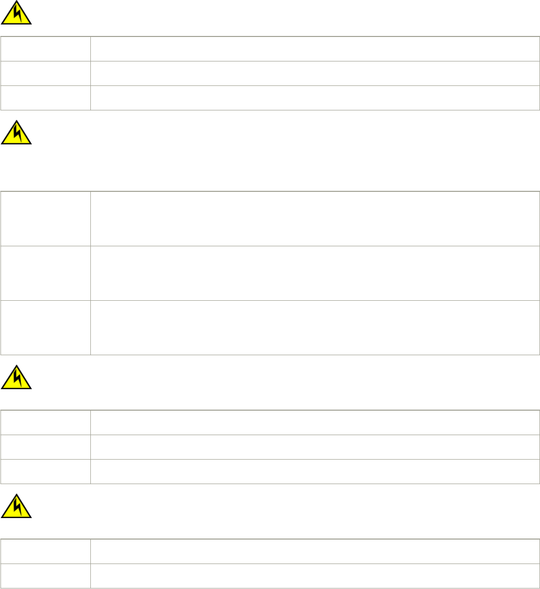
Electrical cautions
CAUTION
Use a separate branch circuit for each power cord, which provides redundancy in case one of the circuits fails.
VORSICHT Es empehlt sich die Installation eines separaten Stromkreiszweiges für jede Elektroschnur als Redundanz im Fall des Ausfalls
eines Stromkreises.
MISE EN GARDE Utilisez un circuit de dérivation diérent pour chaque cordon d’alimentation ainsi, il y aura un circuit redondant en cas de
panne d’un des circuits.
PRECAUCIÓN Use un circuito derivado separado para cada cordón de alimentación, con lo que se proporcionará redundancia en caso de
que uno de los circuitos falle.
CAUTION
Ensure that the device does not overload the power circuits, wiring, and over-current protection. To determine the
possibility of overloading the supply circuits, add the ampere (amp) ratings of all devices installed on the same circuit as the
device. Compare this total with the rating limit for the circuit. The maximum ampere ratings are usually printed on the
devices near the input power connectors.
VORSICHT Stromkreise, Verdrahtung und Überlastschutz dürfen nicht durch das Gerät überbelastet werden. Addieren Sie die
Nennstromleistung (in Ampere) aller Geräte, die am selben Stromkreis wie das Gerät installiert sind. Somit können Sie
feststellen, ob die Gefahr einer Überbelastung der Versorgungsstromkreise vorliegt. Vergleichen Sie diese Summe mit der
Nennstromgrenze des Stromkreises. Die Höchstnennströme (in Ampere) stehen normalerweise auf der Geräterückseite
neben den Eingangsstromanschlüssen.
MISE EN GARDE Assurez-vous que le dispositif ne risque pas de surcharger les circuits d'alimentation, le câblage et la protection de
surintensité. Pour déterminer le risque de surcharge des circuits d'alimentation, additionnez l'intensité nominale (ampères) de
tous les dispositifs installés sur le même circuit que le dispositif en question. Comparez alors ce total avec la limite de charge
du circuit. L'intensité nominale maximum en ampères est généralement imprimée sur chaque dispositif près des connecteurs
d'entrée d'alimentation.
PRECAUCIÓN Verique que el instrumento no sobrecargue los circuitos de corriente, el cableado y la protección para sobrecargas. Para
determinar la posibilidad de sobrecarga en los circuitos de suministros, añada las capacidades nominales de corriente (amp)
de todos los instrumentos instalados en el mismo circuito que el instrumento. Compare esta suma con el límite nominal para
el circuito. Las capacidades nominales de corriente máximas están generalmente impresas en los instrumentos, cerca de los
conectores de corriente de entrada.
CAUTION
Before plugging a cable into to any port, be sure to discharge the voltage stored on the cable by touching the electrical
contacts to ground surface.
VORSICHT Bevor Sie ein Kabel in einen Anschluss einstecken, entladen Sie jegliche im Kabel vorhandene elektrische Spannung, indem
Sie mit den elektrischen Kontakten eine geerdete Oberäche berühren.
MISE EN GARDE Avant de brancher un câble à un port, assurez-vous de décharger la tension du câble en reliant les contacts électriques à la
terre.
PRECAUCIÓN Antes de conectar un cable en cualquier puerto, asegúrese de descargar la tensión acumulada en el cable tocando la
supercie de conexión a tierra con los contactos eléctricos.
CAUTION
If you do not install a module or a power supply in a slot, you must keep the slot ller panel in place. If you run the chassis
with an uncovered slot, the system will overheat.
VORSICHT Falls kein Modul oder Netzteil im Steckplatz installiert wird, muss die Steckplatztafel angebracht werden. Wenn ein Steckplatz
nicht abgedeckt wird, läuft das System heiß.
MISE EN GARDE Si vous n’installez pas de module ou de bloc d'alimentation dans un slot, vous devez laisser le panneau du slot en place. Si
vous faites fonctionner le châssis avec un slot découvert, le système surchauera.
Cautions
Brocade FCX Series Hardware Installation Guide
Part Number: 53-1003616-03 105
PRECAUCIÓN Si no instala un módulo o un fuente de alimentación en la ranura, deberá mantener el panel de ranuras en su lugar. Si pone en
funcionamiento el chasis con una ranura descubierta, el sistema sufrirá sobrecalentamiento.
Danger Notices
A Danger statement indicates conditions or situations that can be potentially lethal or extremely hazardous to you. Safety labels are also
attached directly to products to warn of these conditions or situations.
Ein Gefahrenhinweis warnt vor Bedingungen oder Situationen die tödlich sein können oder Sie extrem gefährden können.
Sicherheitsetiketten sind direkt auf den jeweiligen Produkten angebracht um vor diesen Bedingungen und Situationen zu warnen.
Un paragraphe Danger indique des conditions ou des situations potentiellement mortelles ou extrêmement dangereuses. Des labels de
sécurité sont posés directement sur le produit et vous avertissent de ces conditions ou situations
Una advertencia de peligro indica condiciones o situaciones que pueden resultar potencialmente letales o extremadamente peligrosas.
También habrá etiquetas de seguridad pegadas directamente sobre los productos para advertir de estas condiciones o situaciones.
General dangers
DANGER
The procedures in this manual are for qualied service personnel.
GEFAHR Die Vorgehensweisen in diesem Handbuch sind für qualiziertes Servicepersonal bestimmt.
DANGER Les procédures décrites dans ce manuel doivent être eectuées par un personnel de maintenance qualié.
PELIGRO Los procedimientos de este manual deben llevarlos a cabo técnicos cualicados.
Electrical dangers
DANGER
Before beginning the installation, see the precautions in “Power precautions.”
GEFAHR Vor der Installation siehe Vorsichtsmaßnahmen unter “Power Precautions” (Vorsichtsmaßnahmen in Bezug auf elektrische
Ablagen).
DANGER Avant de commencer l'installation, consultez les précautions décrites dans “Power Precautions” (Précautions quant à
l'alimentation).
PELIGRO Antes de comenzar la instalación, consulte las precauciones en la sección “Power Precautions” (Precauciones sobre corriente).
DANGER
Disconnect the power cord from all power sources to completely remove power from the device.
GEFAHR Ziehen Sie das Stromkabel aus allen Stromquellen, um sicherzustellen, dass dem Gerät kein Strom zugeführt wird.
DANGER Débranchez le cordon d'alimentation de toutes les sources d'alimentation pour couper complètement l'alimentation du
dispositif.
PELIGRO Para desconectar completamente la corriente del instrumento, desconecte el cordón de corriente de todas las fuentes de
corriente.
Danger Notices
Brocade FCX Series Hardware Installation Guide
106 Part Number: 53-1003616-03
DANGER
If the installation requires a dierent power cord than the one supplied with the device, make sure you use a power cord
displaying the mark of the safety agency that denes the regulations for power cords in your country. The mark is your
assurance that the power cord can be used safely with the device.
GEFAHR Falls für die Installation ein anderes Stromkabel erforderlich ist (wenn das mit dem Gerät gelieferte Kabel nicht passt), müssen
Sie sicherstellen, dass Sie ein Stromkabel mit dem Siegel einer Sicherheitsbehörde verwenden, die für die Zertizierung von
Stromkabeln in Ihrem Land zuständig ist. Das Siegel ist Ihre Garantie, dass das Stromkabel sicher mit Ihrem Gerät verwendet
werden kann.
DANGER Si l'installation nécessite un cordon d'alimentation autre que celui fourni avec le dispositif, assurez-vous d'utiliser un cordon
d'alimentation portant la marque de l'organisation responsable de la sécurité qui dénit les normes et régulations pour les
cordons d'alimentation dans votre pays. Cette marque vous assure que vous pouvez utiliser le cordon d'alimentation avec le
dispositif en toute sécurité.
PELIGRO Si la instalación requiere un cordón de corriente distinto al que se ha suministrado con el instrumento, verique que usa un
cordón de corriente que venga con la marca de la agencia de seguridad que dena las regulaciones para cordones de
corriente en su país. Esta marca será su garantía de que el cordón de corriente puede ser utilizado con seguridad con el
instrumento.
DANGER
For safety reasons, the ESD wrist strap should contain a series 1 megaohm resistor.
GEFAHR Aus Sicherheitsgründen sollte ein EGB-Armband zum Schutz von elektronischen gefährdeten Bauelementen mit einem 1
Megaohm-Reihenwiderstand ausgestattet sein.
DANGER Pour des raisons de sécurité, la dragonne ESD doit contenir une résistance de série 1 méga ohm.
PELIGRO Por razones de seguridad, la correa de muñeca ESD deberá contener un resistor en serie de 1 mega ohmio.
DANGER
Risk of explosion if battery is replaced by an incorrect type. Dispose of used batteries according to the instructions.
GEFAHR Es besteht Explosionsgefahr, wenn ein unzulässiger Batterietyp eingesetzt wird.
Verbrauchte Batterien sind entsprechend den geltenden Vorschriften zu entsorgen.
DANGER Risque d'explosion en cas de remplacement de la pile par un modèle incorrect.
Débarrassez-vous des piles usagées conformément aux instructions.
PELIGRO Riesgo de explosión si se sustituye la batería por una de tipo incorrecto.
Deshágase de las baterías usadas de acuerdo con las instrucciones.
DANGER
To avoid high voltage shock, do not open the device while the power is on.
GEFAHR Das eingeschaltete Gerät darf nicht geönet werden, da andernfalls das Risiko eines Stromschlags mit Hochspannung
besteht.
DANGER An d'éviter tout choc électrique, n'ouvrez pas l'appareil lorsqu'il est sous tension.
PELIGRO Para evitar una descarga de alto voltaje, no abra el dispositivo mientras esté encendido.
Danger Notices
Brocade FCX Series Hardware Installation Guide
Part Number: 53-1003616-03 107
Dangers related to equipment weight
DANGER
Make sure the rack housing the device is adequately secured to prevent it from becoming unstable or falling over.
GEFAHR Stellen Sie sicher, dass das Gestell für die Unterbringung des Geräts auf angemessene Weise gesichert ist, so dass das
Gestell oder der Schrank nicht wackeln oder umfallen kann.
DANGER Vériez que le bâti abritant le dispositif est bien xé an qu'il ne devienne pas instable ou qu'il ne risque pas de tomber.
PELIGRO Verique que el bastidor que alberga el instrumento está asegurado correctamente para evitar que pueda hacerse inestable o
que caiga.
DANGER
Mount the devices you install in a rack as low as possible. Place the heaviest device at the bottom and progressively place
lighter devices above.
GEFAHR Montieren Sie die Geräte im Gestell so tief wie möglich. Platzieren Sie das schwerste Gerät ganz unten, während leichtere
Geräte je nach Gewicht (je schwerer desto tiefer) darüber untergebracht werden.
DANGER Montez les dispositifs que vous installez dans un bâti aussi bas que possible. Placez le dispositif le plus lourd en bas et le plus
léger en haut, en plaçant tous les dispositifs progressivement de bas en haut du plus lourd au plus léger.
PELIGRO Monte los instrumentos que instale en un bastidor lo más bajos posible. Ponga el instrumento más pesado en la parte inferior
y los instrumentos progresivamente más livianos más arriba.
Laser dangers
DANGER
All ber-optic interfaces use Class 1 lasers.
GEFAHR Alle Glasfaser-Schnittstellen verwenden Laser der Klasse 1.
DANGER Toutes les interfaces en bres optiques utilisent des lasers de classe 1.
PELIGRO Todas las interfaces de bra óptica utilizan láser de clase 1.
Danger Notices
Brocade FCX Series Hardware Installation Guide
108 Part Number: 53-1003616-03
