RuggON MC7354 Single Modular User Manual PX 501 UM
RuggON Corporation Single Modular PX 501 UM
RuggON >
Contents
- 1. User manual
- 2. Users Manual-1
- 3. Users Manual-2
- 4. User manual_Part 1
- 5. User manual_Part 2
User manual_Part 2
34
Operation
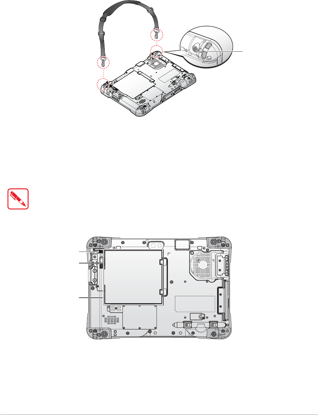
Removing the Shoulder Strap
1. Press in the clips to release them from the metal loop.
2. Remove the clips.
Metal Loop
Figure 43. Removing the Shoulder Strap
Installing the Standard Battery
The following instructions are for both standard and external batteries. The external battery is an
optional component. Only use components specifically designed for this device. Contact your local
representative for ordering information.
Make sure the power switch is switched to ON before installing the standard/external
battery. See “First Time Use” on page 18.
1. Place the device display side down on a clean work surface.
2. Locate the battery.
Battery
Release Button
Locking Switch
Figure 44. Rear View: Locating the Battery
35
Operation
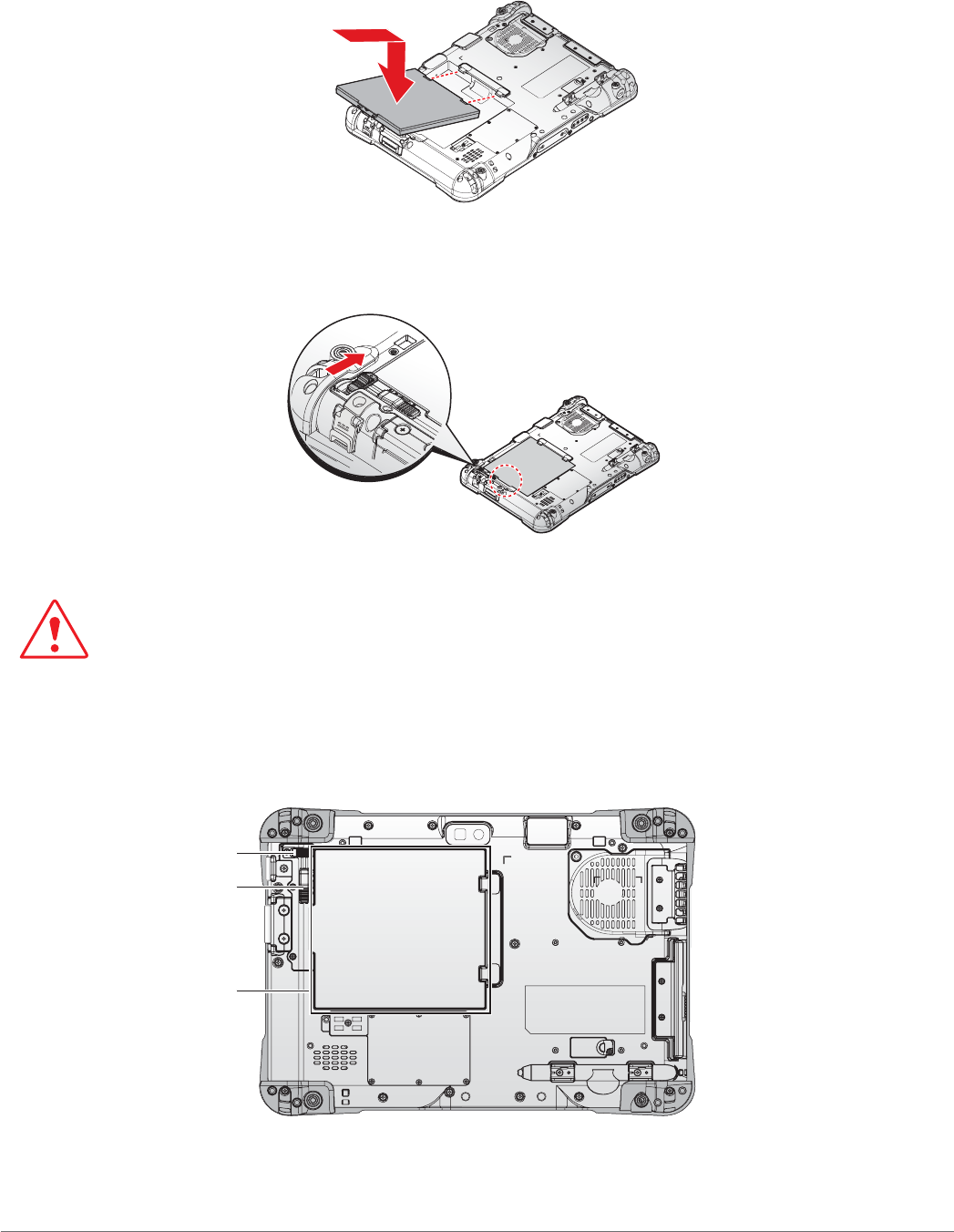
3. Align the tabs on the battery with the slots on the chassis.
4. Angle the battery in place and set the tabs in the chassis slots.
5. Lower the raised end of the battery and press in place until an audible click is heard.
Figure 45. Installing the Battery
6. Slide the locking switch on the top-left side to lock the battery.
Figure 46. Locking the Battery
0DNHVXUHWKHODWFKLVVHFXUHO\ORFNHGWRSUHYHQWWKHEDWWHU\IURPIDOOLQJ
Removing the Standard Battery
1. Place the device display side down on a clean work surface.
2. Locate the battery.
Battery
Release Button
Locking Switch
Figure 47. Rear View: Locating the Battery
36
Operation
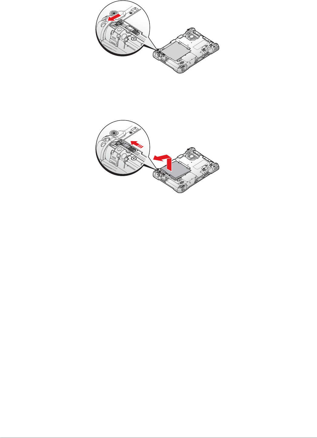
3. Slide the locking switch on the top-left side to the unlock position.
Figure 48. Unlock the Battery
4. Press and hold the release button as shown in the image to release the battery.
5. Hold the battery and angle the left side up to remove.
Figure 49. Removing the Battery
Connecting to a Wireless Network
Before you can make use of the PX-501 wireless functions, you need to connect to a network. The
following is a set of procedures for connecting to a wireless network.
1. Before beginning, make sure your Wi-Fi setting is enabled and you are within range of a
wireless network. If your Wi-Fi setting is disabled, proceed to step 2.
Look at the Network icon located at the right side of the taskbar. If the icon displays an
X in a red circle, you are not within range of a wireless network. Move to a different spot
until the Wi-Fi icon changes status indicating availability to a wireless network.
2. From any screen, open the Charms bar by sliding your finger inward from the screen’s right
edge. The Charms bar displays along the screen’s right side.
3. In the Charms bar, tap Settings to open the Settings menu.
4. In Settings, tap the Network icon to display the Networks connection settings.
5. The Wi-Fi menu displays. By default, the Wi-Fi menu is set to Off. Tap the bar next to Off to
toggle Wi-Fi to On. This enables the Wi-Fi option.
6. Once W-Fi is enabled a listing of all available wireless networks displays. The wireless
networks with the strongest signal are atop the list.

37
Operation
7. Select the network you want to connect to, and tap the Connect button. You can tap the
Connect Automatically check box if you connect to this network frequently. If you connect
to the network, you are finished with the process. The network is considered an Open
unsecured network, no passoword is required.
8. If a password is required, type the password in the Enter the network security key
field. Alternatively, you can also push the WPS button on your router to begin the security
handshake.
9. Tap Next to finish the connection process.
You have successfully connected to a wireless network.
38
Using BIOS Setup Utility
Chapter 4. Using BIOS Setup Utility
Your ruggedized tablet has a BIOS setup utility which allows you to configure important system
settings, including settings for the Boot and AP menus as well as the device’s basic settings--the
system reads the basic settings during initialization in order to boot correctly
When to Use the BIOS Setup Utility
You need to run the BIOS Setup utility when:
Restoring to BIOS settings to factory default
Modifying specific hardware settings
Modifying specific settings to optimize system performance
Installing Windows 7 operating system
Accessing the BIOS Setup Utility
The BIOS Setup Utility screens shown in this chapter are for your reference only. The
actual images or settings on your tablet computer may differ.
The BIOS Setup Utility program may have been updated after the publication of this
manual.
To run the BIOS Setup Utility, use the following procedures:
1. Perform one of the following:
If the PX-501 is powered off
Press the Power button to start up the device. The power LED lights.
Quickly press and hold the Windows Home key until the BIOS Post screen displays.
If the PX-501 is powered on
Press the Power button to shut down the device.
Quickly press and hold the Windows Home Key until the BIOS Post screen displays.
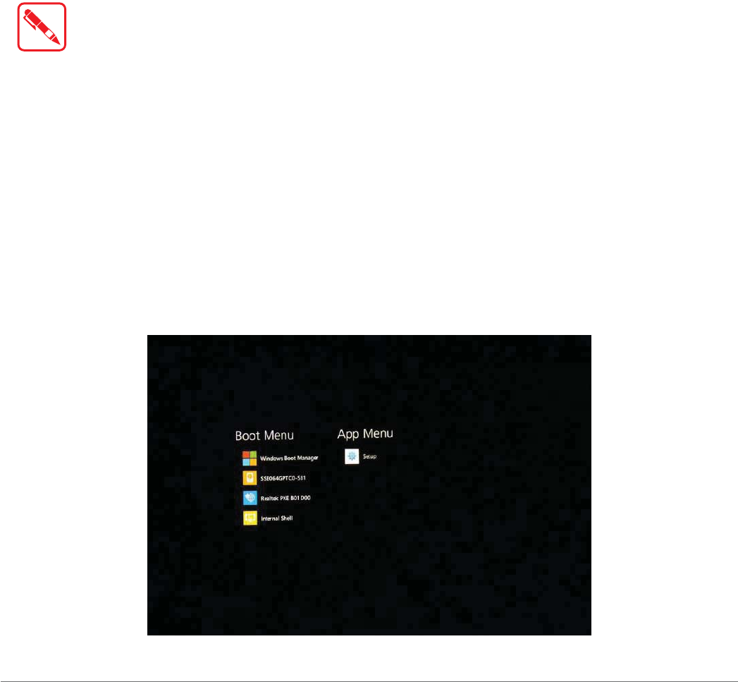
The BIOS POST screen appears as shown.
2. From the BIOS POST screen select App Menu to open the BIOS Setup Utility.
Figure 50. BIOS POST Screen
39
Using BIOS Setup Utility
Due to the device’s fast boot up and boot down time, there is only a small time frame of a few
seconds between the release of the Power button and the opportunity to press the Windows Home
key.
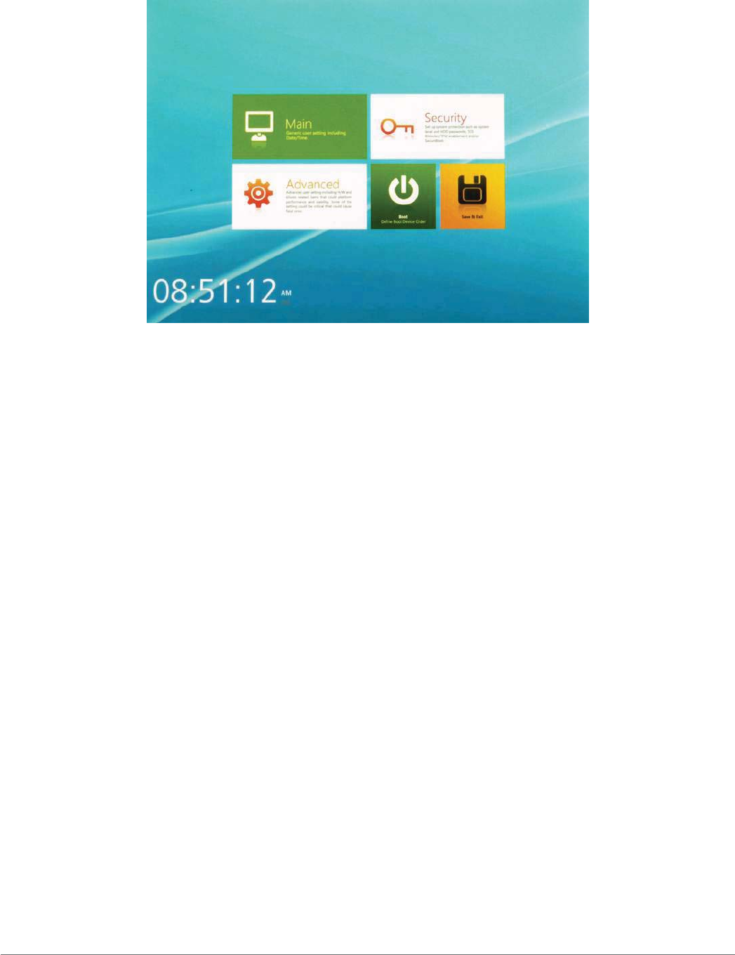
The App Menu displays.
Figure 51. BIOS Setup Utility: App Menu Screen
Installation an Operating System
Setting Up a Windows 7 Installation Environment
There are several settings in BIOS that must be modified before you can install a Windows 7
operating system.
Use the following guidelines to prepare the BIOS environment:
Step 1: Enable CSM Support
1. Access the BIOS Setup Utility, see “Accessing the BIOS Setup Utility” on page 38.
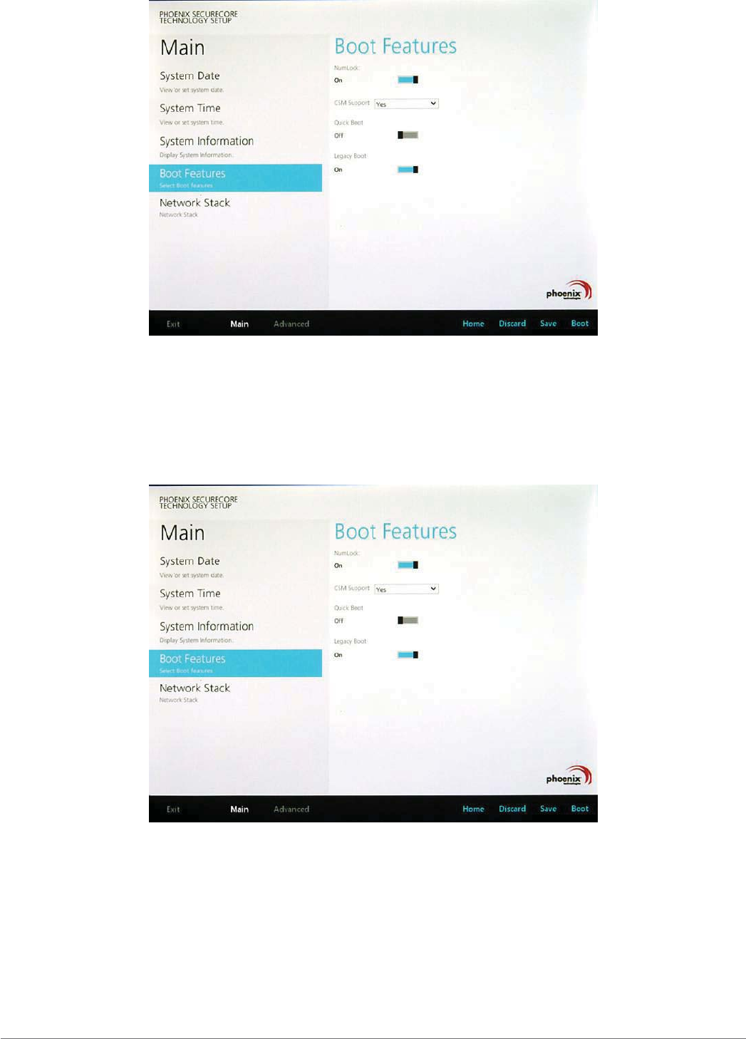
2. Navigate to APP Menu > Main > Boot Features.
3. Locate the CSM Support setting and tap the drop-down menu to display the options.
40
Using BIOS Setup Utility
4. Tap Yes to enable CSM support.
Figure 52. Main > Boot Features
Step 2 Enable Legacy Boot
1. Access the BIOS Setup Utility, see “Accessing the BIOS Setup Utility” on page 38.
2. Navigate to APP Menu > Main > Boot Features.
3. Locate the Legacy Boot setting and tap on the menu to select On enable legacy boot.
Figure 53. Main > Boot Features
Step 3: Advanced > Miscellaneous Configuration
Save the Settings
After you configure BIOS, you will need to save the settings.
41
Using BIOS Setup Utility
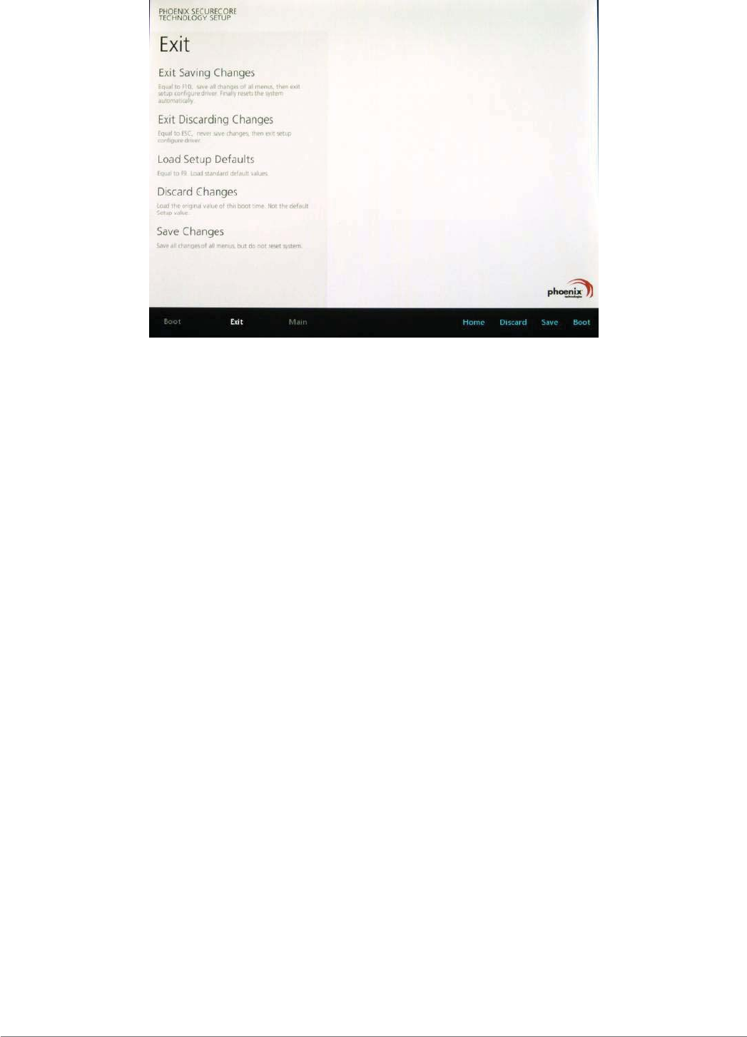
1. Navigate to APP Menu > Exit and tap Exit Saving Changes.
Figure 54. Exit the BIOS Utility
2. A prompt display, tap Yes to save the configuration.
The BIOS settings are configured and the Windows 7 operating system can be installed.
42
Using BIOS Setup Utility
BIOS Passwords
Setting Up a Supervisor Password
To setup a supervisor password, follow the procedure as described:
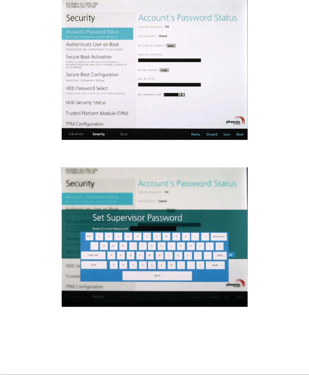
1. Go to APP Menu > Security > Account’s Password Status.
2. Tap the Enter icon next to Setup the Supervisor Password to access the virtual keyboard.
Figure 55. Security > Account’s Password Status
3. Tap the password to use for the Supervisor profile and tap Enter.
Figure 56. Set Supervisor Password

43
Using BIOS Setup Utility
4. Verification of the password is required. Tap the same password again and tap Enter to
confirm the new password.
5. Navigate to APP Menu > Exit.
Figure 57. Exit Screen
6. Tap Exit Saving Changes to display the confirmation screen.
7. Tap Yes to save the new configuration settings.
After setting the Supervisor password, the password is required to access the BIOS Setup Utility.
Changing a Supervisor Password
1. Navigate to APP Menu > Security > Account’s Password Status.
2. Tap the Enter icon next to Setup Supervisor Password.
3. Enter the current supervisor password.
4. Enter a new password.
5. Enter the new password again to confirm.
6. Go to APP Menu > Exit.
7. Tap Exit Saving Changes and tap Yes to save the configuration.
Resetting a Supervisor Password
A supervisor password can not be reset. In the event that you forget the supervisory password,
you will need to reflash the BIOS to enter the BIOS menus. Refer to “Updating BIOS” on page
44 to reflash the BIOS.
44
Using BIOS Setup Utility
EC and BIOS
Updating BIOS
This procedure allows you to update and reflash the system BIOS. Both procedures follow the
same steps as described in the following.
0DNHVXUHWRSURWHFW\RXUGHYLFHIURPSRZHUORVVGXULQJWKH%,26XSGDWHSURFHGXUHWRSUHYHQW
LUUHSDUDEOHGDPDJHWR\RXUV\VWHP¶VPDLQERDUG
For this procedure, it is highly recommended to connect the device to the AC adapter to prevent a
sudden loss of power during the BIOS updating process.
1. Contact your technical sales or technical representative to obtain the correct BIOS file.
2. Copy the BIOS file on to the USB device.
3. Connect the USB device to one of the device’s USB ports and power on the PX-501.
A USB keyboard is required for entering command.
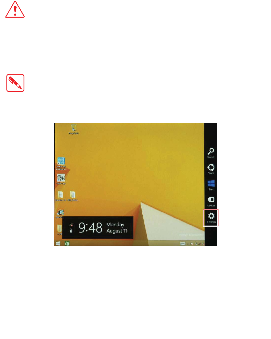
4. Once the device is on and the Windows 8 Home screen displays, open the Charms bar by
sliding your finger inward from the screen’s right edge. The Charms bar displays.
5. Tap Settings from the displayed menus.
Figure 58. Charms Bar > Settings
45
Using BIOS Setup Utility
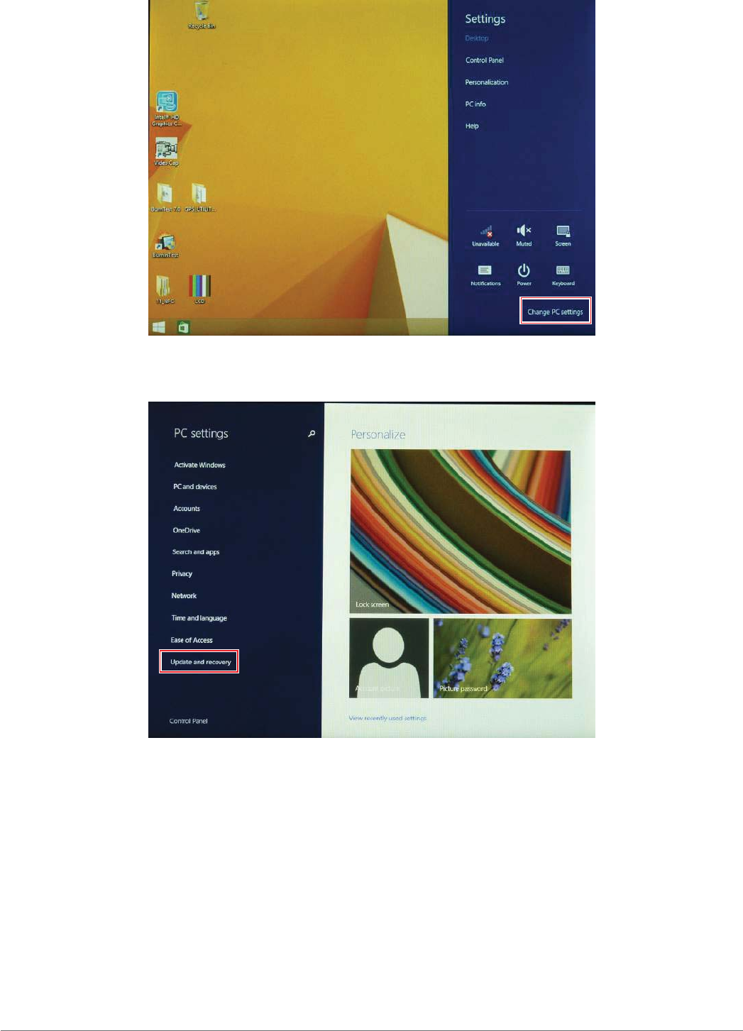
6. Tap Change PC settings.
Figure 59. Change PC Settings
7. From the PC settings menu, tap Update and recovery to continue.
Figure 60. Update and Recovery
46
Using BIOS Setup Utility
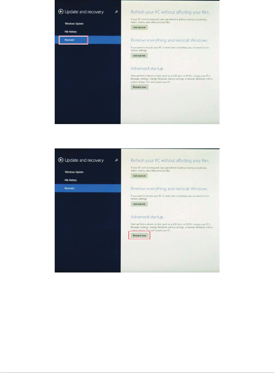
8. From the Update and recovery screen, tap Recovery.
The Advanced startup option displays.
Figure 61. Recovery
9. Under Advanced startup, tap Restart now.
Figure 62. Restart Now
47
Using BIOS Setup Utility
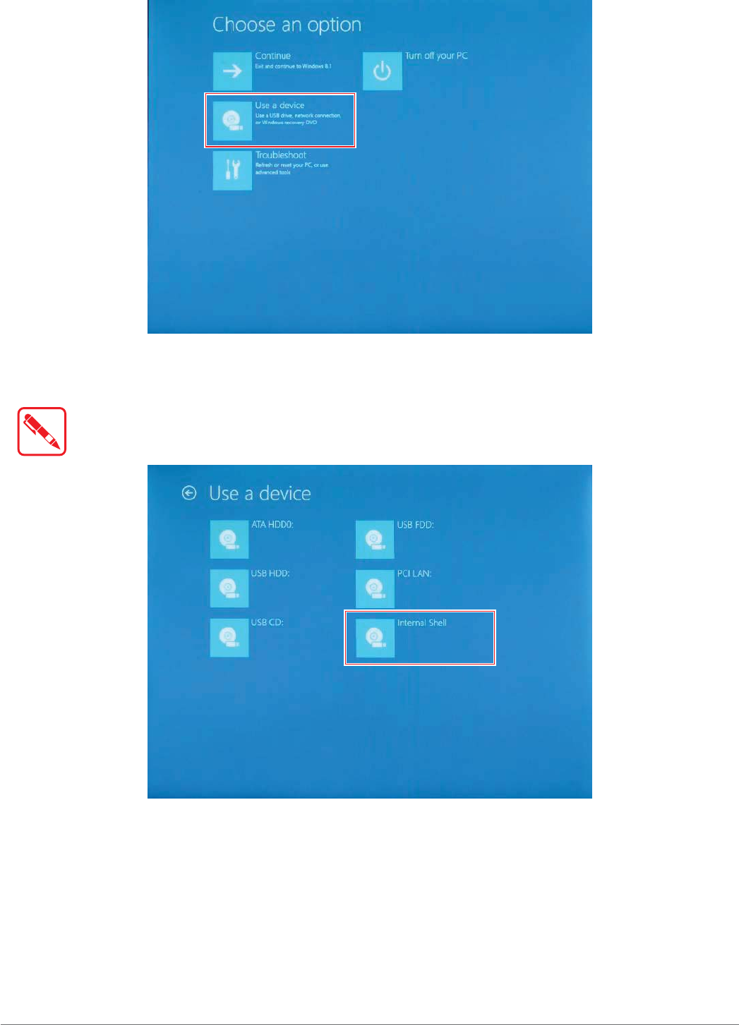
10. Tap Use a device to select a boot up preference.
Figure 63. Use a Device
11. From the Use a device menu, tap Internal Shell to open the command screen.
Make sure connect the PX-501 to the AC adapter to prevent a sudden loss of power.
Figure 64. Internal Shell
48
Using BIOS Setup Utility
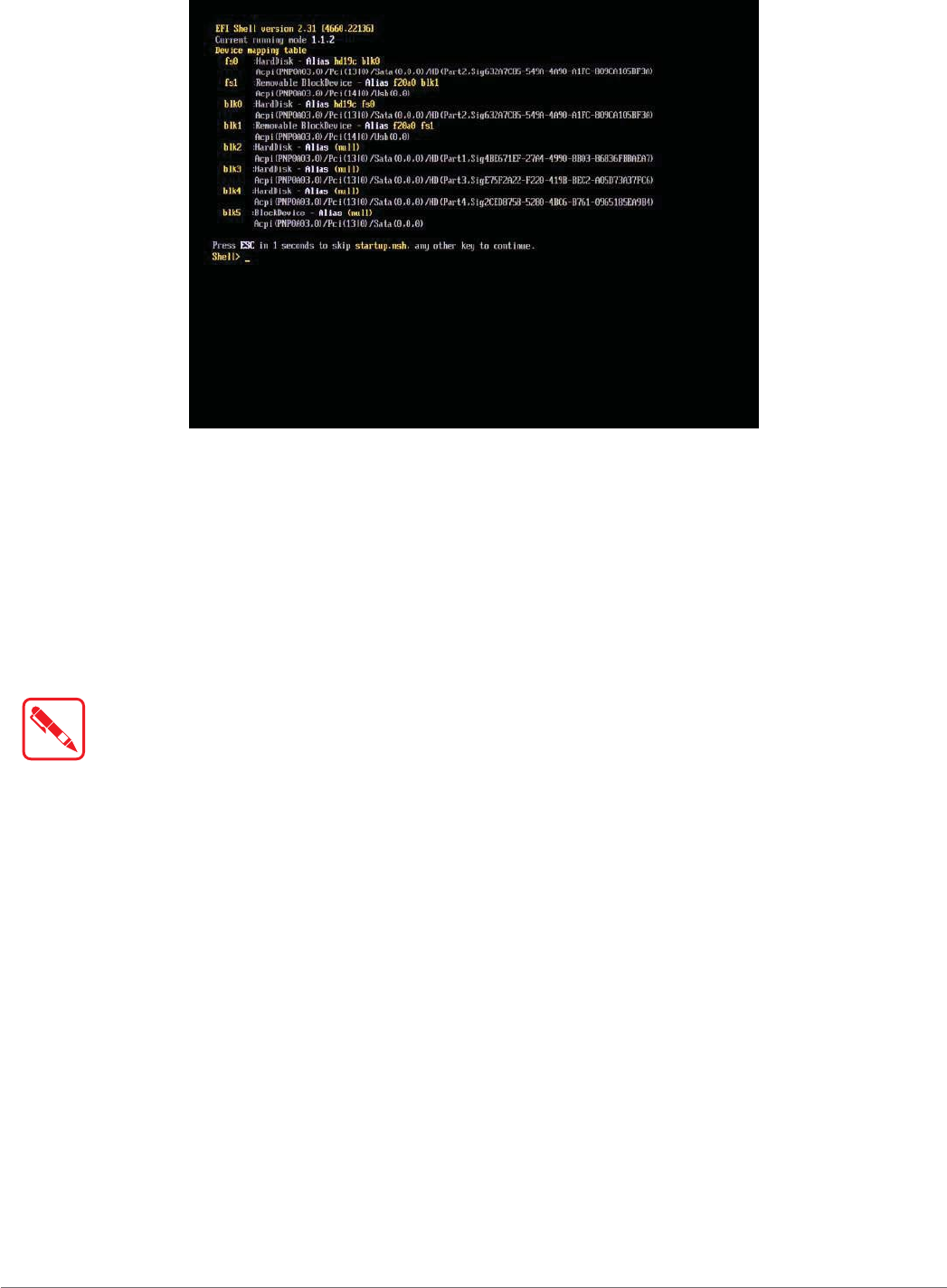
12. In the command screen, enter fs1: to select the USB device already connected to the
device. The command directs you to the USB device’s root menu.
Figure 65. Internal Shell Command Screen
13. If the BIOS file is in a folder and not in the root directory, navigate to the target folder.
14. Type wf (.nsh) and tap Enter. wf is the designated BIOS file.
Do not turn off your device or interfere with the reflash process until the process is complete.
15. Once the process is complete, the PX-501 automatically reboots.
The BIOS is now updated.
Updating EC
Connect the PX-501 to the AC adapter to prevent a sudden loss of power.
1. Updating EC requires the use of the Internal Shell Command menu, refer to steps 1 to 12 of
“Updating BIOS”.
2. Enter the EC source file folder.
3. In the source folder, enter f.
4. Do not turn off your device or interfere with the reflash process until the process is complete.
The system reboots once the process is completed.
49
Using the DashON Utility
Chapter 5. Using the DashON Utility
Overview
The DashON resident program is designed to provide near-instant access to your device’s settings
and configuration within a single, easy to use interface.
The following information illustrates and describes the various settings available for configuration
through the DashON menus.
Important: Do not terminate the DashON program from the task manager or the ambient light
sensor to prevent the function buttons from malfunctioning.
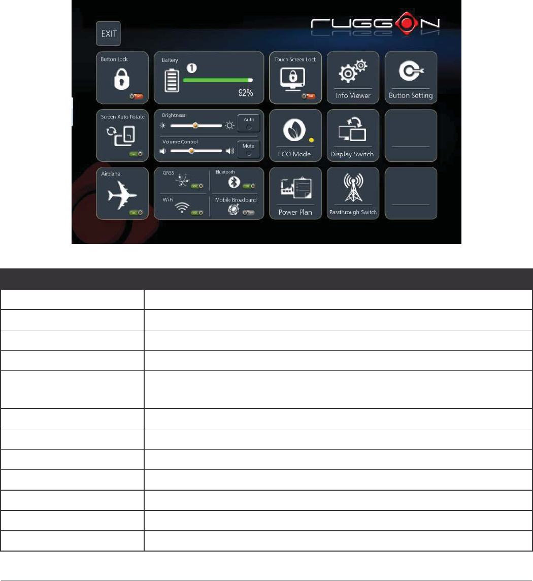
Figure 70. DashON Overview
Function Description
EXIT Close DashON and return to the desktop.
Button Lock Lock or unlock the function keys on PX-501.
Screen Auto Rotate Disable or enable screen auto rotate function.
Airplane Turn on or off the airplane mode.
Battery Shows the battery level or charging status.
Note: The function is only available on Windows 7.
Brightness Adjust brightness level for PX-501.
Volume Control Adjust volume level for PX-501.
GNSS Disable or enable GNSS function.
Wi-Fi Disable or enable Wi-Fi function.
Bluetooth Disable or enable Bluetooth function.
Mobile Broadband Disable or enable mobile broadband function.
Touch Screen Lock Lock or unlock the touch screen.
50
Using the DashON Utility
Function Description
ECO Mode
Disable or enable ECO mode to save battery life when using the
device.
Note: The function is only available on Windows 7.
Power Plan Manage how your PX-501 uses power.
Note: The function is only available on Windows 7.
Info Viewer View PX-501 system specifications. The menu is for display only.
Display Switch Choose a display mode when connect to another output device.
Pass-through Switch Connect to the pass-through switch.
Button Setting Pre-defined functions settings. Supports function button customizing.
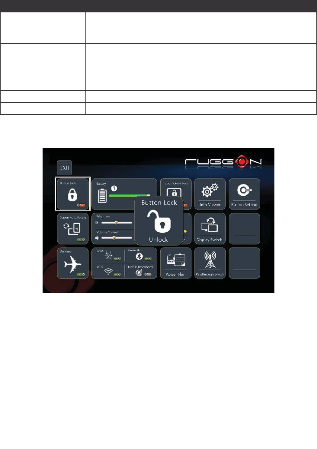
Button Lock
The Button Lock function disables or enables the use of the functions buttons. Tap to enable or
disable the function.
Figure 71. Button Lock
51
Using the DashON Utility
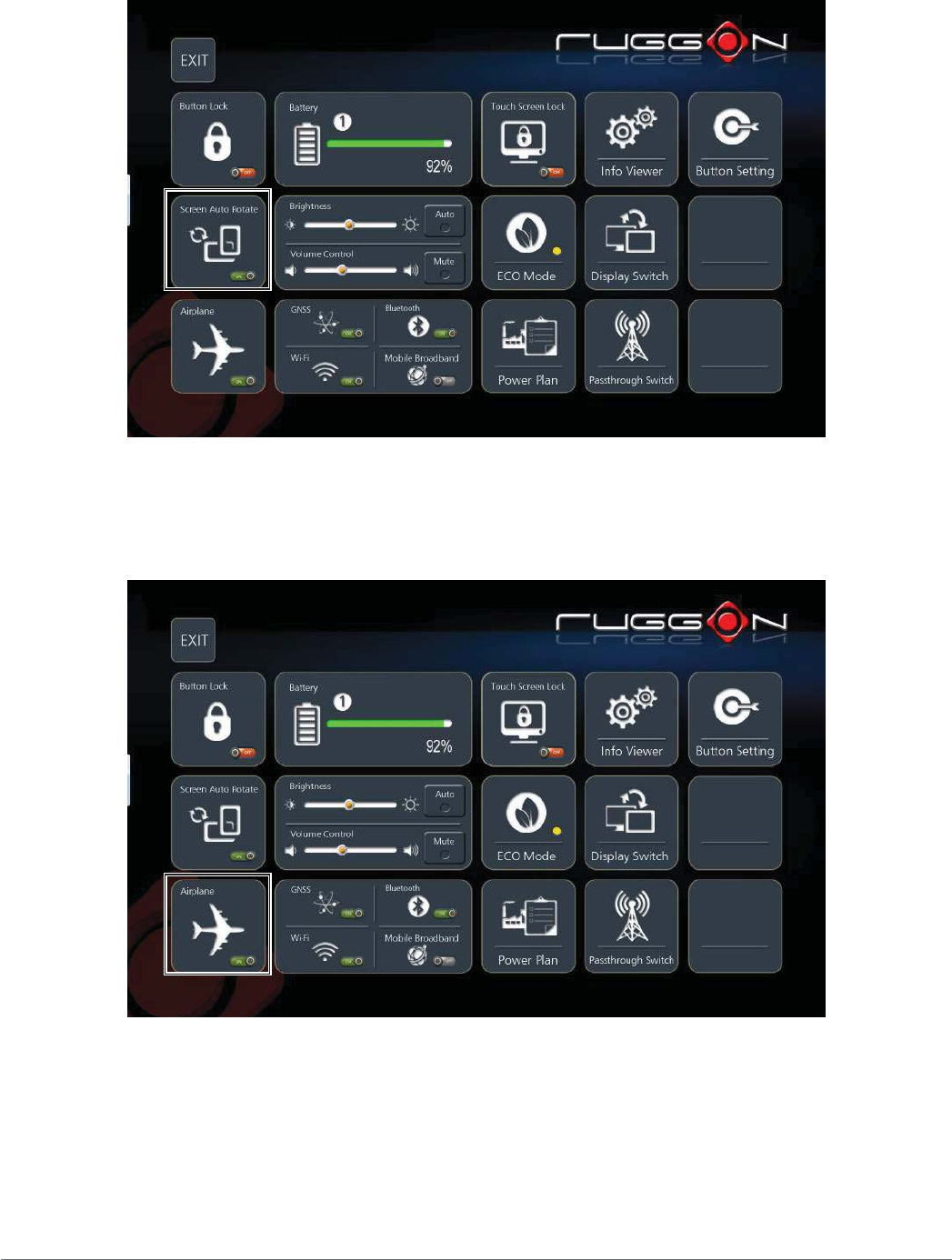
Screen Auto Rotate
The Screen Auto Rotate function disables or enables the auto screen rotation when the device is
being rotated. Tap to enable or disable the function.
Figure 72. Screen Auto Rotate
Airplane Mode
The Airplane function disables or enables Airplane Mode. While in Airplane Mode all functions
except broadcasting functionality are available. Tap to enable or disable the function.
Figure 73. Airplane Mode
52
Using the DashON Utility
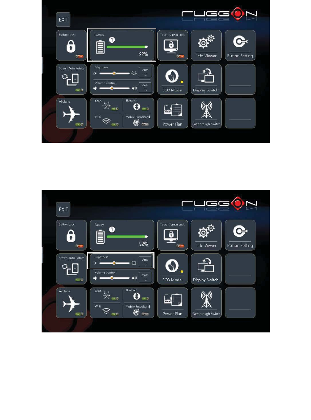
Battery
Shows the battery level or charging status.
Figure 74. Battery
Brightness
The Brightness function disables or enables the auto brightness function. Tap to enable or disable
the function. The slide bar allows for manual adjustment of the brightness setting.
Figure 75. Brightness
53
Using the DashON Utility
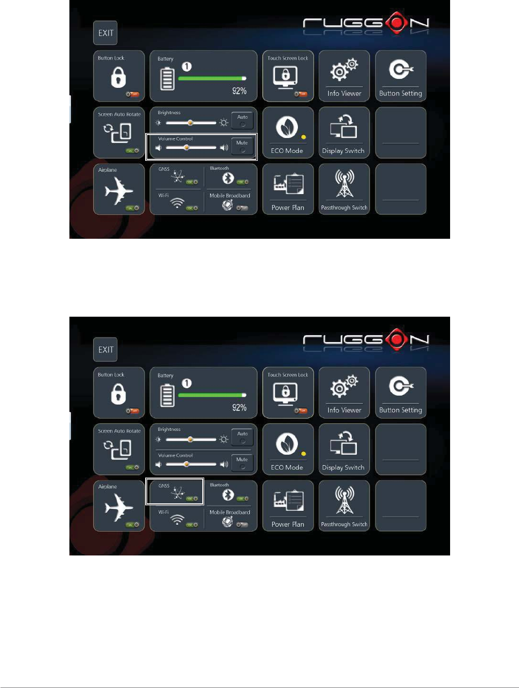
Volume Control
The Volume Control function disables or enables the mute function. Tap to enable or disable the
function. The slide bar allows for manual adjustment of the volume level.
Figure 76. Volume Control
GNSS
The GNSS function disables or enables the Global Navigation Satellite System module. Tap to
enable or disable the function.
Figure 77. GNSS
54
Using the DashON Utility
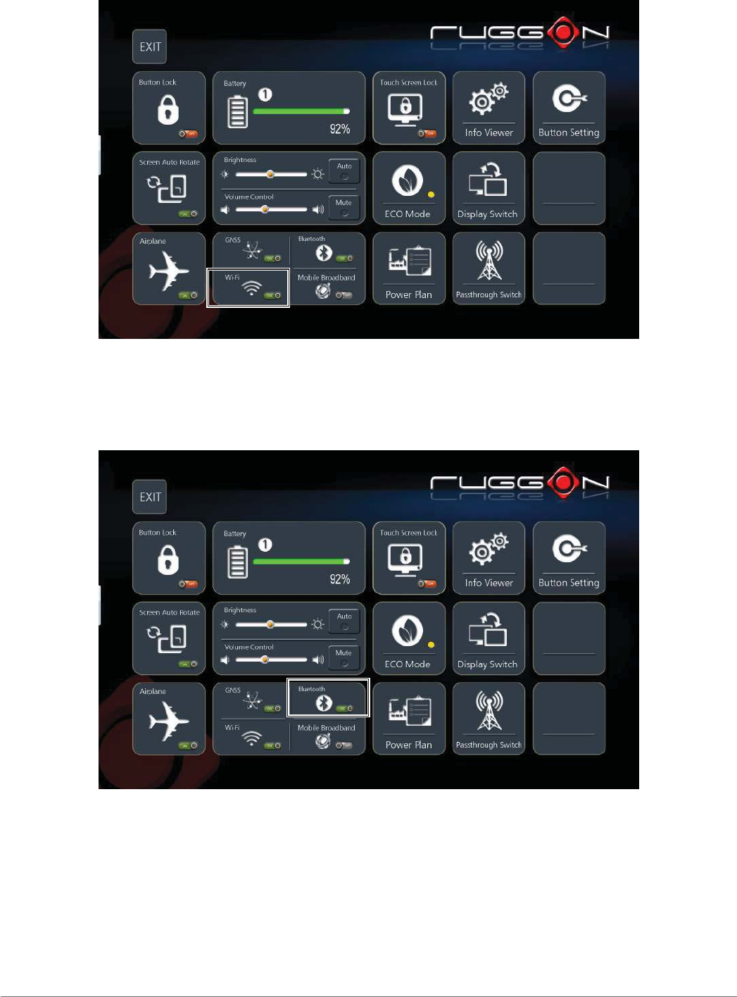
Wi-Fi
The Wi-Fi function disables or enables wireless module. Tap to enable or disable the function.
Figure 78. Wi-Fi
Bluetooth
The Bluetooth function disables or enables bluetooth module. Tap to enable or disable the
function.
Figure 79. Bluetooth
55
Using the DashON Utility
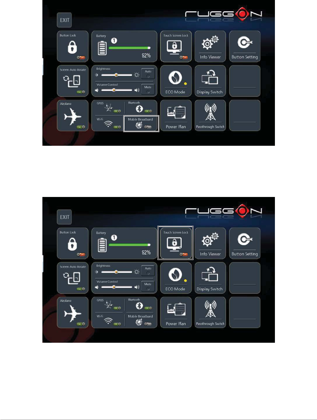
Mobile Broadband
The Mobile Broadband function disables or enables mobile broadband module. Tap to enable or
disable the function.
Figure 80. Mobile Broadband
Touch Screen Lock
The Touch Screen Lock function disables the touch functionality on the screen.
Tap to enable or disable the function.
Figure 81. Touch Screen Lock
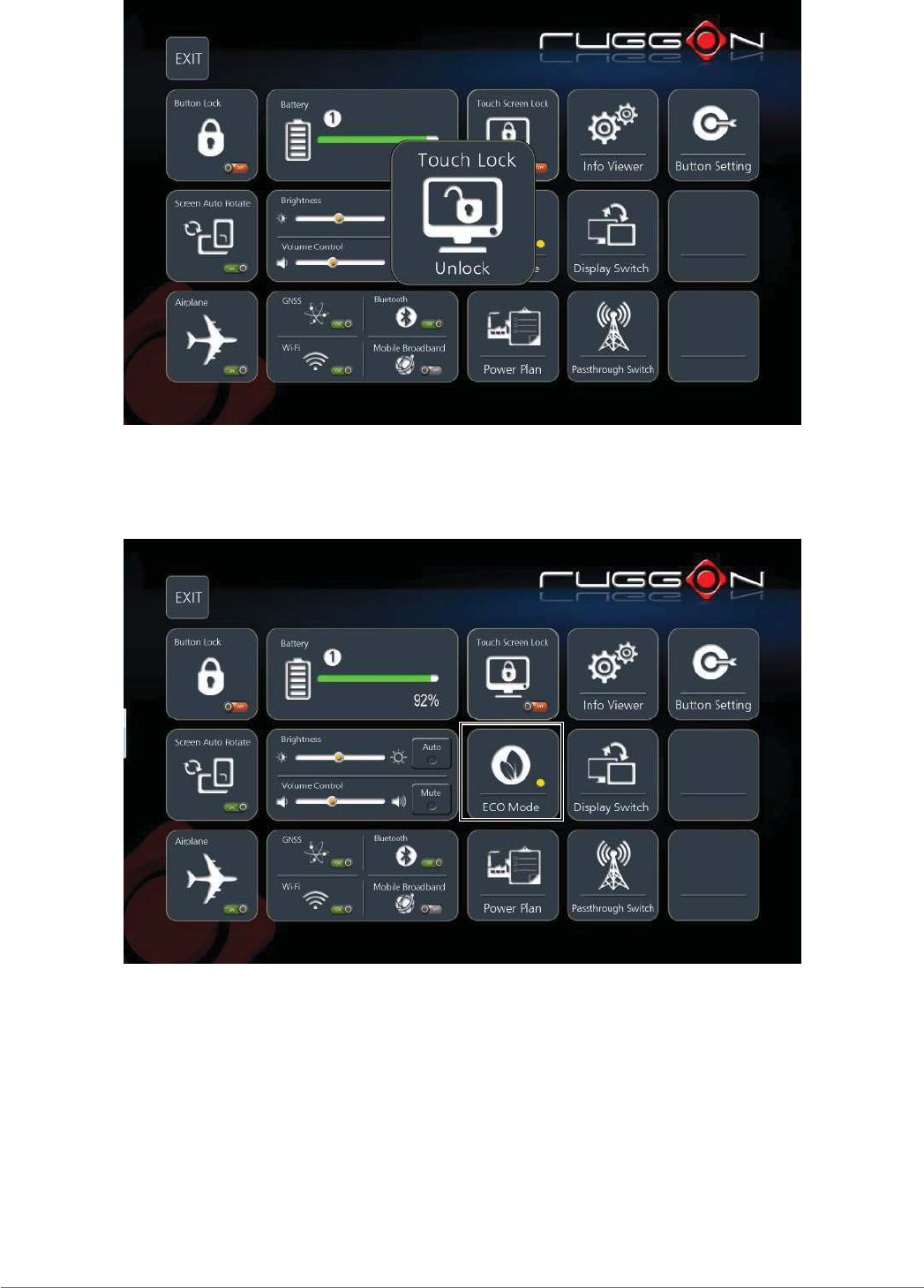
56
Using the DashON Utility
To enable touch functionality, tap the Fn key until the Touch Screen Unlocked screen displays.
Figure 82. Unlock Touch Screen
ECO Mode
The ECO Mode provides three states: On, Auto, and Off, to help in battery life management.
Figure 83. ECO Mode
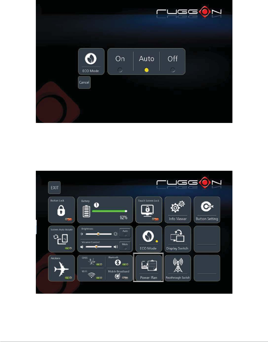
57
Using the DashON Utility
Tap On to enable the mode whenever the device is turned on.
Tap Auto to allow the utility to select periods of inactivity to power down.
Tap Off to disable the ECO Mode.
Tap Cancel to return to the main menu.
Figure 84. ECO Mode Menu
Power Plan
The Power Plan provides settings to manage how the device uses and conserves power. A
power plan can be setup to maximize the device performance, save energy or balance energy
conservation with performance.
Figure 85. Power Plan
58
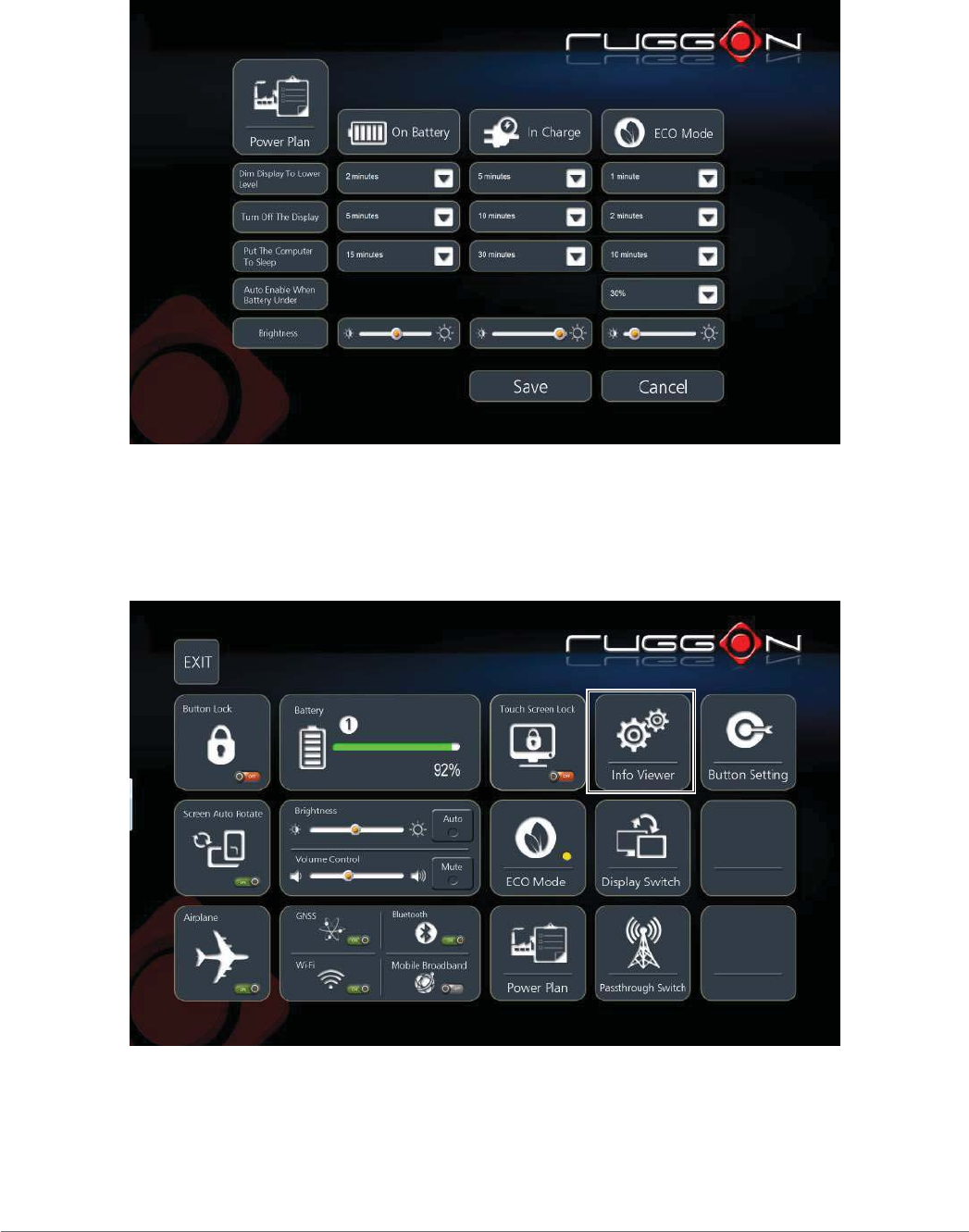
Using the DashON Utility
Modify the On Battery, In Charge, or ECO Mode states to define the power scheme best suited to
your needs.
To modify the a power plan, tap the drop-down menu of the relevant setting, then tap Save to
create the new power plan scheme. Alternatively, tap Cancel to return to the previous screen
without saving.
Figure 86. Power Plan Menu
Info Viewer
The Info Viewer displays the system’s hardware specifications.
Tap to display system information. The setting is for display purposes only.
Figure 87. Info Viewer
59
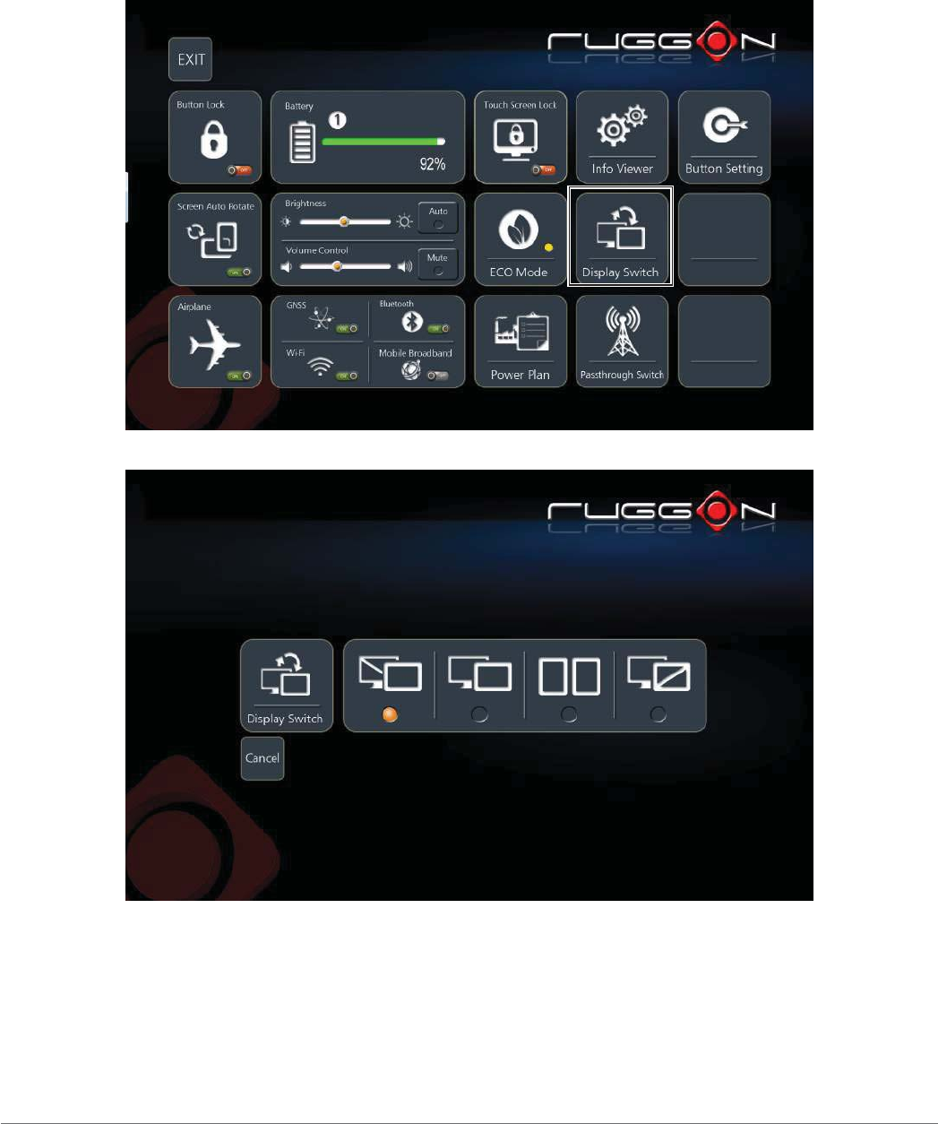
Using the DashON Utility
Display Switch
The Display Switch function supports four types of display options:
View desktop on main display
View desktop on main display and show extended display
Duplicate both displays
View desktop on extended display.
Figure 88. Display Switch
Figure 89. Display Switch Menu
60
Using the DashON Utility
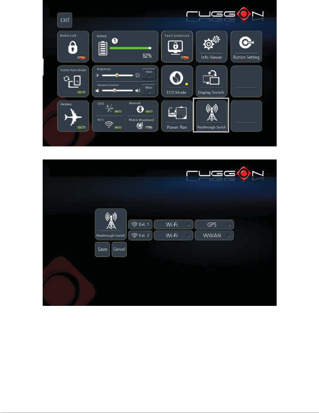
Pass-through Switch
This function is only available when an antenna pass-through is connected to the port, see
“Bottom View” on page 13. GPS, WWAN and Wi-Fi settings are available once the optional RF
antenna is connected.
Figure 90. Pass-through Switch
Figure 91. Pass-through Switch Menu
61
Using the DashON Utility
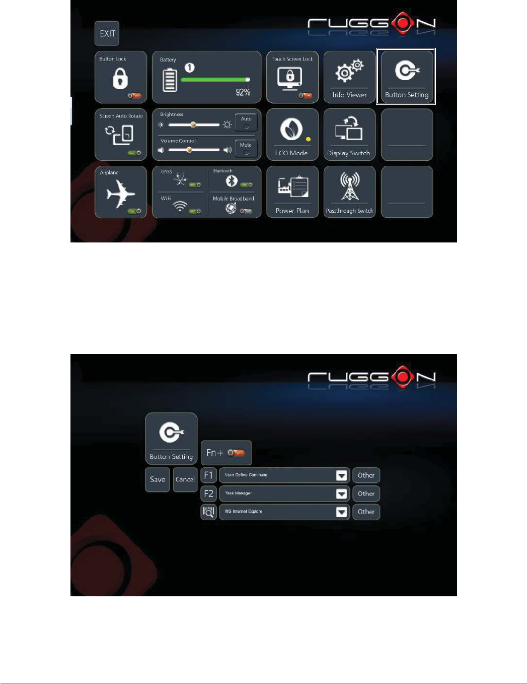
Button Setting
The external function buttons are configured with pre-defined commands. However, the buttons
can be configured to open any number of executable commands. In combination with the Fn key,
the function buttons can trigger up to six different commands.
Figure 92. Button Setting
Select the function key to define and tap the drop-down menu to choose from a pre-defined list of
commands.
Alternatively, tap Other to select a specific executable file to attach to the function key.
Additional shortcuts can be created by enabling the Fn + button. This allows the creation of a
second set of short cuts available by pressing Fn + Function Button.
Figure 93. Button Setting Menu

62
Troubleshooting
Chapter 6. Troubleshooting
Use the troubleshooting tables in this section to fix problems with the Wi-Fi connection, 802.1x
security, or general problems with operating the computer.
If you send the computer in for service, it is your responsibility to save the computer
data and configuration. RuggON is responsible only for ensuring that the hardware
matches the original configuration when repairing or replacing the computer.
Troubleshoot the Wi-Fi Connection
Use this troubleshooting table to help solve problems with your 802.11 radio connection.
Q. When you turn on the computer after it was suspended for a while (10 to 15 minutes or
longer), it can no longer send or receive messages over the network.
A. Host may have deactivated or lost current terminal emulation session. In a TCP/IP direct
connect network, turn off the “Keep Alive” message from host to maintain the TCP session
while the computer is suspended.
Q. The computer is connected to the network and you move to a new site to collect data. Your
computer now shows you are not connected to the network.
A. Move closer to an access point or to a different location to reestablish communications until
you reconnect with the network.
Q. The computer appears to be connected to the network, but you cannot establish a terminal
emulation session with the host computer.
A. There may be a problem with the host computer, or with the connection between the access
point and the host computer. Check with the network administrator to make sure the host is
running and allowing users to log in to the system.
Q. The computer appears to be connected to the network, but the host computer is not receiving
any information from the computer.
A. There may be a problem with the connection between the access point and the host
computer. Check with the network administrator or use your access point user’s manual.
Q. A network connection icon appears in the toolbar, but then disappears.
A. The computer may not be communicating with the intended access point. Make sure the
network name matches the access point network name.
The access point may not be communicating with the server. Ensure the access point is
turned on, properly configured, and has 802.1x security enabled.

63
Troubleshooting
Troubleshoot Operating the Computer
Use this section to troubleshoot problems that may prevent you from being able to operate the
computer.
Q. You press the Power button and nothing happens.
A. Make sure that power is connected to the computer.
Q. The computer appears to be locked up and you cannot enter data.
A. Restart the computer.
Call Product Support
Simple instructions please contact the dealer, contact ruggon representative, or leave a message
visit the RuggON website at www.ruggon.com.
To better assist you have the following information ready:
Configuration number
Serial number
Operating system, BIOS, and MCU versions
Service pack version
System component versions
If you are using security, know the type and the full set of parameters

64
Maintenance
Chapter 7. Maintenance
Cleaning the Device
Danger to electric shock when cleaning or maintaining the PX-501.
To avoid electric shock, turn the PX-501 off and disconnect it from the power supply before cleaning or
maintaining it.
Housing
The housing of the PX-501 is best cleaned with a damp cloth.
Use compressed air, a high-pressure cleaner or vacuum cleaner may damage the surface.
Use a high-pressure cleaner, the additional risk of water entering the PX-501 may damage
the electronics or touch screen.
Touch Screen
Use neutral detergent or isopropyl alcohol on a clean soft cloth to clean the panel surface.
Prevent using any kind of chemical solvent, acidic or alkali solution.
Returning the Device
Please put the contents in the original package gently when you need to return the PX-501.
Contacting RuggON
If you experience technical difficulties, please consult your distributor or contact the technical
services department:
www.ruggon.com