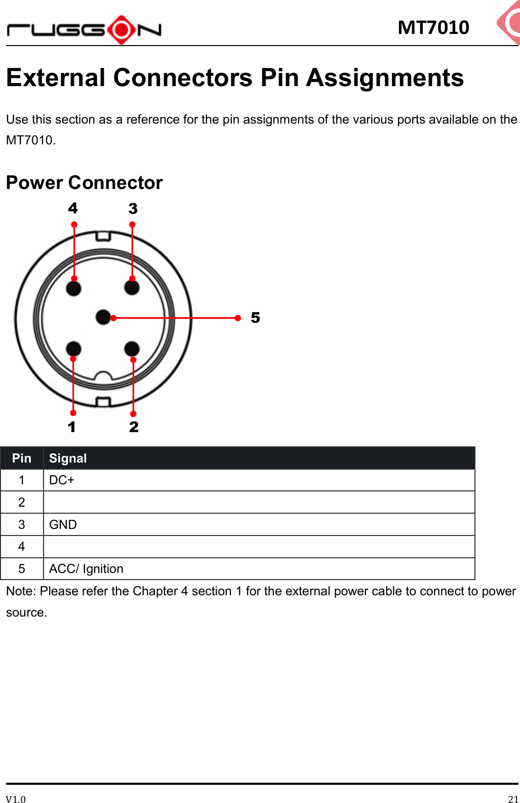
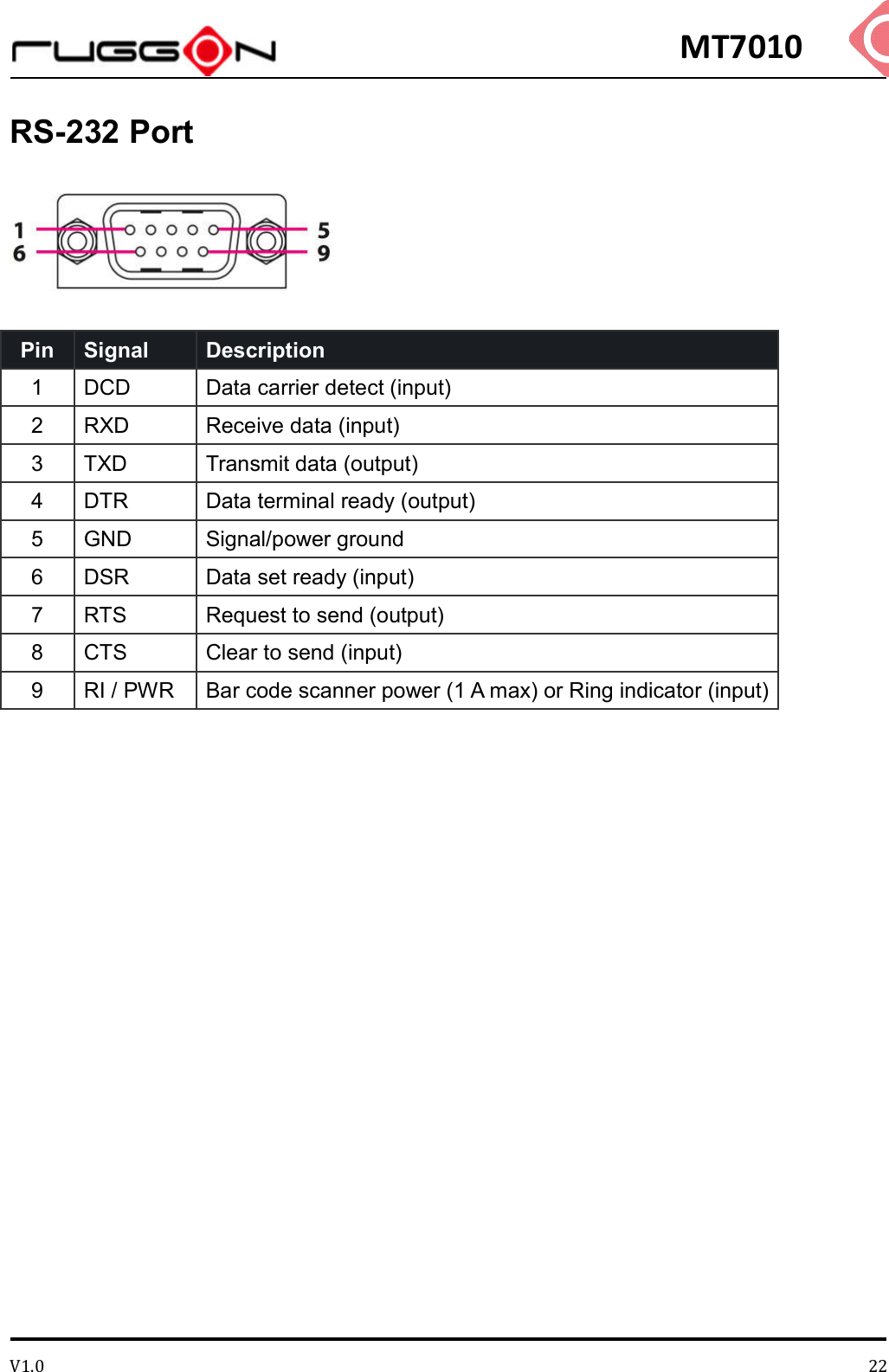
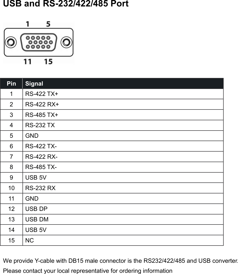
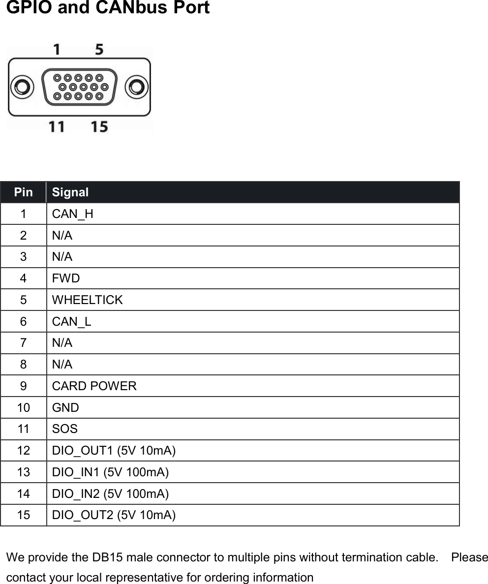
RuggON MT7010 MOBILE DATA TERMINAL User Manual
RuggON Corporation MOBILE DATA TERMINAL Users Manual
UserManual.wiki
>
RuggON
>
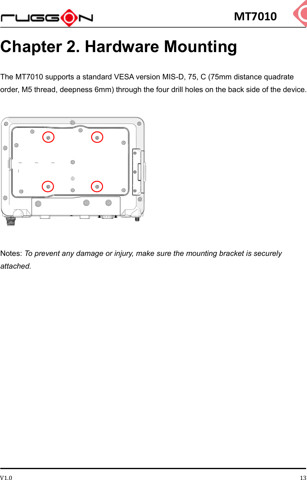
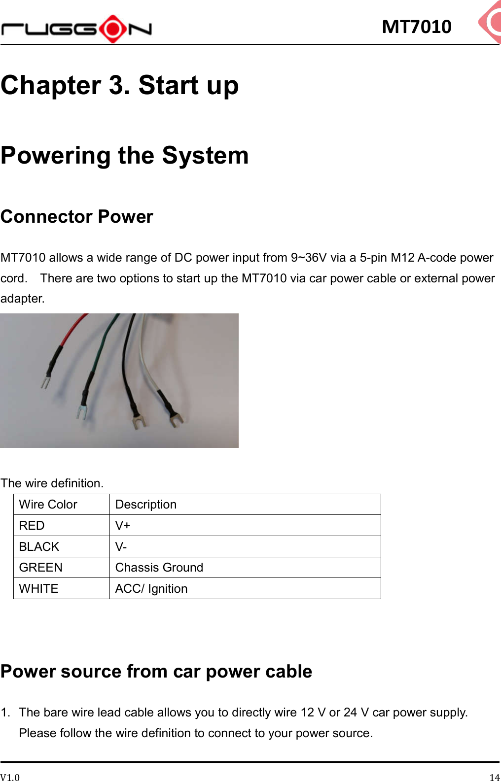
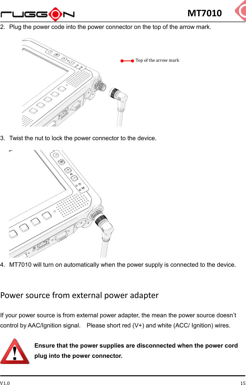
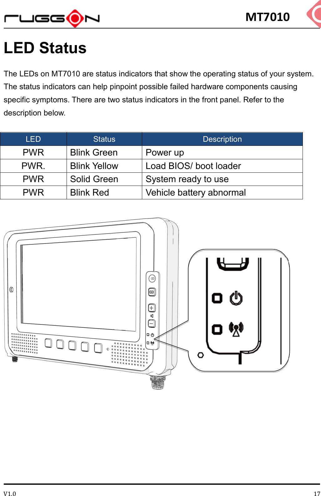
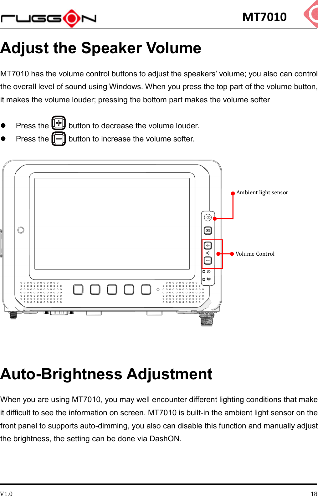
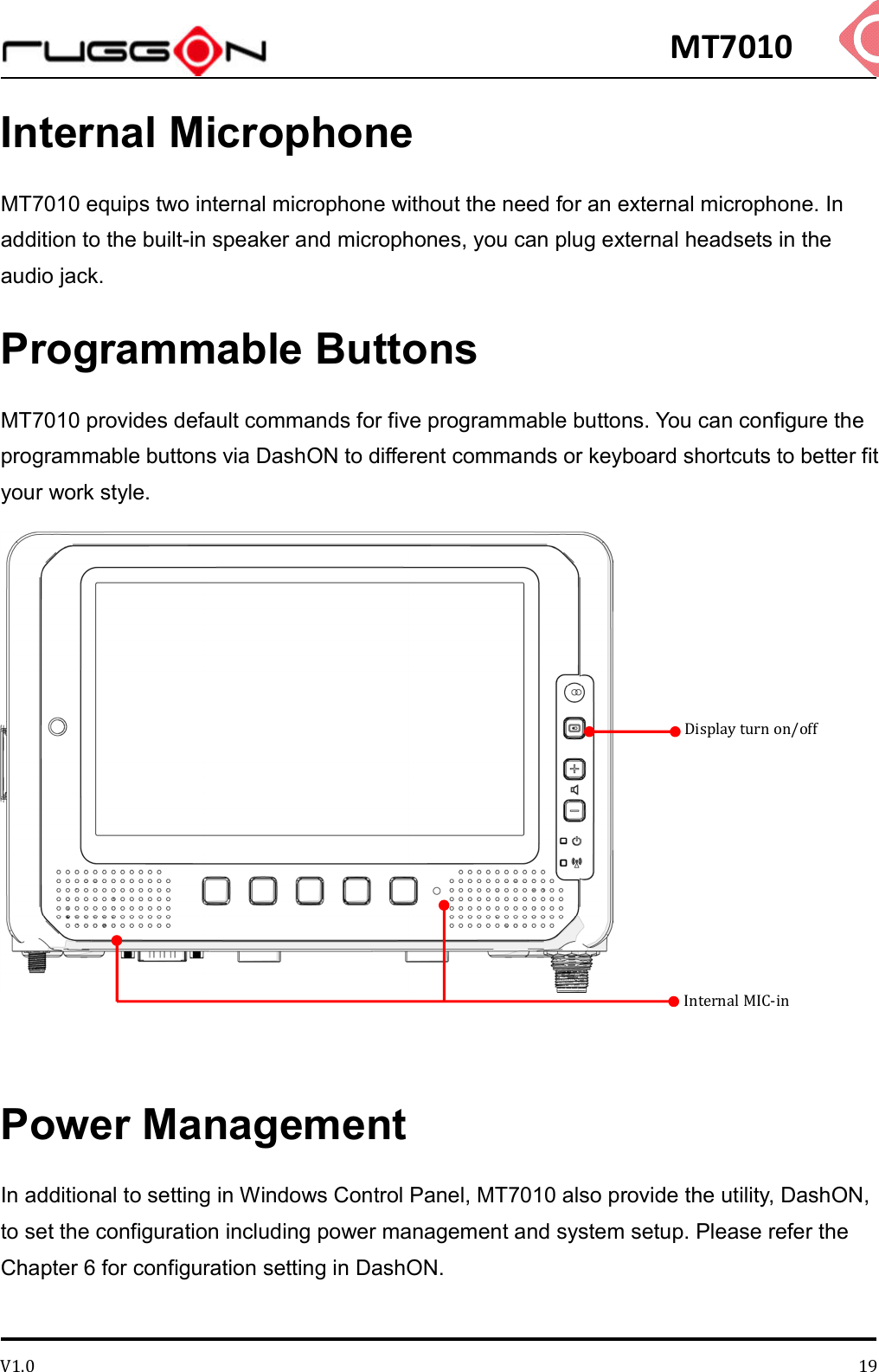
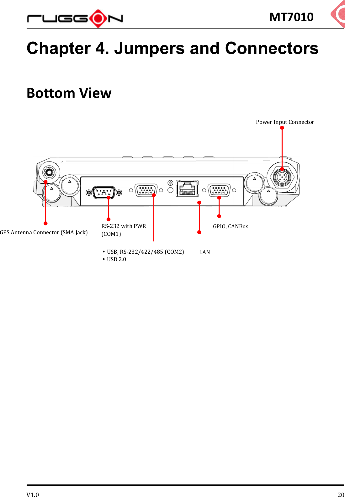
MT7010 User Manual
Users Manual
Navigation menu
Upload a User Manual
Namespaces
Wiki Guide
HTML
PDF
Info
Views
User Manual
Discussion / Help
Navigation