RuggON MT7010 MOBILE DATA TERMINAL User Manual
RuggON Corporation MOBILE DATA TERMINAL Users Manual
RuggON >
Users Manual

MT7010
User’s Manual

MT7010
V1.0
2
Contents
CONTENTS ..................................................................................................................................................................... 2
SAFETY PRECAUTIONS ........................................................................................................................................... 4
REGULATORY AND CERTIFICATION .................................................................................................................. 6
FCC ................................................................................................................................................................................................... 6
CE MARKING .................................................................................................................................................................................. 7
RED .................................................................................................................................................................................................. 7
LITHIUM BATTERY SAFETY STATEMENT ............................................................................................................................... 7
CHAPTER 1. PRODUCT INTRODUCTION .......................................................................................................... 8
HARDWARE SPECIFICATIONS ................................................................................................................................................... 8
OPERATING SYSTEM SUPPORT .............................................................................................................................................. 9
ENVIRONMENT ............................................................................................................................................................................... 9
I/O PORTS .................................................................................................................................................................................... 10
DIMENSION AND WEIGHT ........................................................................................................................................................ 11
MT7010 Standard ....................................................................................................................................................................... 11
PACKAGE LIST ............................................................................................................................................................................ 12
CHAPTER 2. HARDWARE MOUNTING ............................................................................................................. 13
CHAPTER 3. START UP .......................................................................................................................................... 14
POWERING THE SYSTEM ........................................................................................................................................................ 14
Connector Power ........................................................................................................................................................................ 14
Power source from car power cable ............................................................................................................................... 14
Powering Down the System ................................................................................................................................................. 16
LED STATUS................................................................................................................................................................................ 17
ADJUST THE SPEAKER VOLUME .......................................................................................................................................... 18
AUTO-BRIGHTNESS ADJUSTMENT ...................................................................................................................................... 18
INTERNAL MICROPHONE ......................................................................................................................................................... 19
PROGRAMMABLE BUTTONS ................................................................................................................................................... 19
POWER MANAGEMENT ............................................................................................................................................................ 19
CHAPTER 4. JUMPERS AND CONNECTORS ................................................................................................ 20
BOTTOM VIEW ............................................................................................................................................................................... 20

MT7010
V1.0
3
EXTERNAL CONNECTORS PIN ASSIGNMENTS ................................................................................................................ 21
Power Connector ........................................................................................................................................................................ 21
RS-232 Port ................................................................................................................................................................................... 22
USB and RS-232/422/485 Port .......................................................................................................................................... 23
GPIO and CANbus Port .......................................................................................................................................................... 24

MT7010
V1.0
4
Safety Precautions
1. Read these safety instructions carefully.
2. Keep this user’s manual for later reference.
3. Disconnect this equipment from any AC outlet before cleaning. Use a damp cloth. Do
not use liquid or spray detergents for cleaning.
4. For plug-in equipment, the power outlet socket must be located near the equipment and
must be easily accessible.
5. Keep this equipment away from humidity.
6. Put this equipment on a stable surface during installation. Dropping it or letting it fall
may cause damage.
7. Do not leave this equipment in either an unconditioned environment or in an above
40oC storage temperature as this may damage the equipment.
8. The openings on the enclosure are for air convection to protect the equipment from
overheating. DO NOT COVER THE OPENINGS.
9. Make sure the voltage of the power source is correct before connecting the equipment
to the power outlet.
10. Place the power cord in a way so that people will not step on it. Do not place anything
on top of the power cord. Use a power cord that has been approved for use with the
product and that it matches the voltage and current marked on the product’s electrical
range label. The voltage and current rating of the cord must be greater than the volt-
age and current rating marked on the product.
11. All cautions and warnings on the equipment should be noted.
12. If the equipment is not used for a long time, disconnect it from the power source to avoid
damage by transient overvoltage.
13. Never pour any liquid into an opening. This may cause fire or electrical shock.
14. Never open the equipment. For safety reasons, the equipment should be opened only
by qualified service personnel.
15. If one of the following situations arises, get the equipment checked by service
personnel:
a. The power cord or plug is damaged.
b. Liquid has penetrated into the equipment.
c. The equipment has been exposed to moisture.

MT7010
V1.0
5
d. The equipment does not work well, or you cannot get it to work according to the
user’s manual.
e. The equipment has been dropped and damaged.
f. The equipment has obvious signs of breakage.
16. Do not place heavy objects on the equipment.
17. The unit uses a three-wire ground cable which is equipped with a third pin to ground the
unit and prevent electric shock. Do not defeat the purpose of this pin. If your outlet does
not support this kind of plug, contact your electrician to replace your obsolete outlet.
18. CAUTION: DANGER OF EXPLOSION IF BATTERY IS INCORRECTLY RE- PLACED.
REPLACE ONLY WITH THE SAME OR EQUIVALENT TYPE REC- OMMENDED BY
THE MANUFACTURER. DISCARD USED BATTERIES ACCORDING TO THE
MANUFACTURER’S INSTRUCTIONS.

MT7010
V1.0
6
Regulatory and Certification
FCC
This device complies with Part 15 of the FCC Rules. Operation is subject to the following two
conditions:
1. This device may not cause harmful interference.
2. This device must accept any interference received, including interference that may
cause undesired operation.
This equipment has been tested and found to comply with the limits for a Class B digital
device, pursuant to Part 15 of the FCC Rules. These limits are designed to provide
reasonable protection against harmful interference in a residential installation. This
equipment generates, uses, and can radiate radio frequency energy and, if not installed and
used in accordance with the instructions, may cause harmful interference to radio
communications. However, there is no guarantee that interference will not occur in a
particular installation. If this equipment does cause harmful interference to radio or television
reception, which can be determined by turning the equipment off and on, the user is
encouraged to try to correct the interference by one or more of the following measures:
Reorient or relocate the receiving antenna.
Increase the separation between the equipment and the receiver.
Connect the equipment into an outlet on a circuit different from that to which the
receiver is connected.
Consult the dealer or an experienced radio/TV technician for help.
Shielded interconnect cables and shielded AC power cable must be employed with this
equipment to insure compliance with the pertinent RF emission limits governing this device.
Changes or modifications not expressly approved by the system’s manufacturer could void
the user’s authority to operate the equipment.
Any changes or modifications not expressly approved by the party responsible
for compliance could void the user’s authority to operate the equipment.
This device is operation in 5.15 – 5.25GHz frequency range, then restricted in
indoor use only, Outdoor operations in the 5.15 – 5.25GHz is prohibit.

MT7010
V1.0
7
.
RF exposure warning
This equipment must be installed and operated in accordance with provided instructions and the
antenna(s) used for this transmitter must be installed to provide a separation distance of at least 20
cm from all persons and must not be co-located or operating in conjunction with any other antenna or
transmitter. End-users and installers must be provide with antenna installation instructions and
transmitter operating conditions for satisfying RF exposure compliance.
CE Marking
This product has passed the CE test for environmental specifications when shielded cables
are used for external wiring. We recommend the use of shielded cables. Please contact your
local representative for ordering information.
This product has passed the CE test for environmental specifications. Test conditions for
passing included the equipment being operated within an industrial enclosure. In order to
protect the product from being damaged by ESD (Electrostatic Discharge) and EMI leakage,
we strongly recommend the use of CE-compliant industrial enclosure products.
RED
This device complies with the essential requirements of the Radio Equipment
Directive (2014/53/EU).
Lithium Battery Safety Statement
Lithium battery inside. Danger of explosion if battery is incorrectly replaced. Replace only
with same or equivalent type recommended by battery manufacturer.
THIS PRODUCT CONTAINS LITHIUM-ION BATTERY PACKS. IT MUST BE DISPOSED OF
PROPERLY. CONTACT LOCAL ENVIRONMENTAL AGENCIES FOR INFORMATION ON
RECYCLING AND DISPOSAL PLANS IN YOUR AREA.
MT7010
V1.0
8
Chapter 1. Product Introduction
MT7010 is the in-vehicle terminal with 7” high resolution display with 500nits brightness and
flexible to expand varied wireless connection capability designed, it’s for the fleet
management, asset management, EOBR and ELDs application.
This includes ISO 7637-2, SAE J1455 and SAE J1113 compliance and optimized power
system design for cold cranking, load dump, transient voltage and ESD.
With IP65 protection rating, wide temperature design, wide power range input, and rich
expanding interfaces supporting in-vehicle connectivity.
Hardware Specifications
Item Description
Processor Qualcomm MSM8909 (Quad-Core Cortex-A7 1.3 GHz)
Memory LPDDR2 RAM 2GB (Europe, North America version)
LPDDR2 RAM 1GB (China version)
Storage eMMC 16GB (Europe, North America version)
eMMC 8GB (China version)
Display
7 inch TFT LCD
500 nits
Viewing angel: 145(H)/ 160(V) (CR>10)
Touch Panel Projected Capacitive Touch Screen
Wireless
Connectivity
802.11 a/b/g/n
Bluetooth 4.1
GPS / GLONASS / BEIDOU (TBD)
Item Description
Power Input 9-36VDC,3.5A
Battery 1950mAh, 3.6V
Housing
(Mechanical) PC+ABS, fanless design
Certification CE, FCC, CB

MT7010
V1.0
9
Operating System Support
Android 5.1
Environment
Operating temperature:
-20°C (-4°F) to 60°C (140°F)
In accordance withMIL-STD-810G CHANGE1 Method 501.6 High Temperature
Procedure II - Operation
In accordance with MIL-STD-810G CHANGE1 Method 502.6 Low Temperature
Procedure II – Operation
Storage temperature:
-30°C (-22°F) to 70 °C (158°F)
In accordance with MIL-STD-810G CHANGE1 Method 501.6 High Temperature
Procedure I – Storage
In accordance with MIL-STD-810G CHANGE1 Method 502.6 Low Temperature
Procedure I - Storage
Relative humidity:5% to 95% @ 30°C (86°F) to 60°C (140°F) non-condensating in
accordance with MIL-STD-810G CHANGE1 Method 507.6 Humidity Procedure II
Aggravated Cycles (Fig 507.6-7)
Vibration Test:
Operating: MIL-STD-810G CHANGE1 Method 514.7 Category 4,
Fig 514.7C-2 Common carrier (US highway truck vibration exposure);
Fig 514.7C-3 Composite two-wheeled trailer;
Fig 514.7C-4 Composite wheeled vehicle
Non-Operating: MIL-STD-810G CHANGE1 Method 514.7 Category 24, Fig
514.7E-1 (General minimum integrity exposure)
Shock Test:
Operation: MIL-STD-810G CHANGE1 Method 516.7 Procedure 1 Functional
Shock
Non-Operation: MIL-STD-810G CHANGE1 Method 516.7 Procedure V Crash
Hazard Shock

MT7010
V1.0
10
I/O Ports
Item Description
Serial 1 x RS-232 (RX, TX)/422/485, non isolation (COM1)
RS-232, with 5V/600mA & 12V/300mA x 1 (COM2)
USB USB 2.0 for host A-type connector (500mA) x 1
Ethernet Gigabit RJ45 x 1
GPIO
DI/ DO x 2
Input: GPI 0~30V
Output:
(1) circuit design reserved for 2 x GPO 5V
(2) default setting 2 x GPO: OC output, High level depends on
external pull up resistor, Up to 30 VDC maximum sink 50 mA per
channel
CAN CANbus and SAE J1939
Audio Headset for Mic-in/ Audio out x 1
Internal Mic-in x 2
Speaker Built-in dual 2W speaker
MT7010
V1.0
11
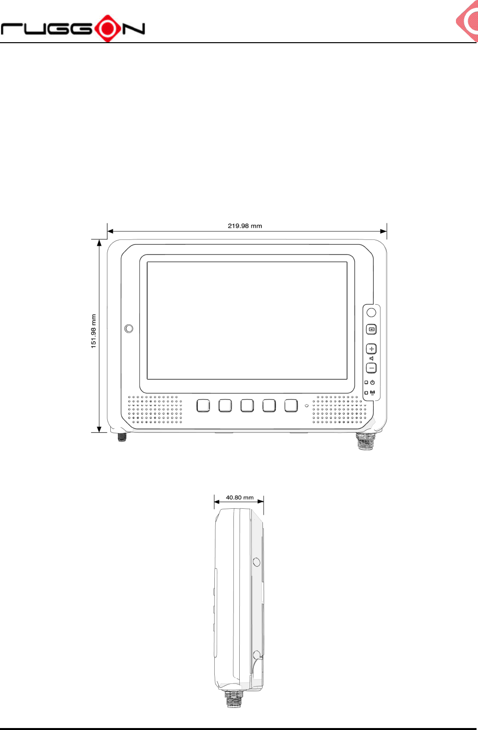
Dimension and Weight
MT7010 Standard
Dimension: 219.98 x 151.98 x 40.8mm / 8.66 x 5.98 x 1.60in. (W x H x D)
Weight: 1.25 kg/ 2.76 lbs.
Front View Dimension
Side View Dimension

MT7010
V1.0
12
Package List
Before you begin the installation or configuration process make sure to inspect all
components and accessories. Contact your representative if there are any missing or
damaged items.
Please verify the delivery of the contents upon receipt
MT7010 in-vehicle terminal
Bare wire power cable with circular power code
NOTE: The packaging material has been selected to optimally protect your device. After
unpacking, store the original packaging material in the event that you need to return
shipment.
MT7010
V1.0
13
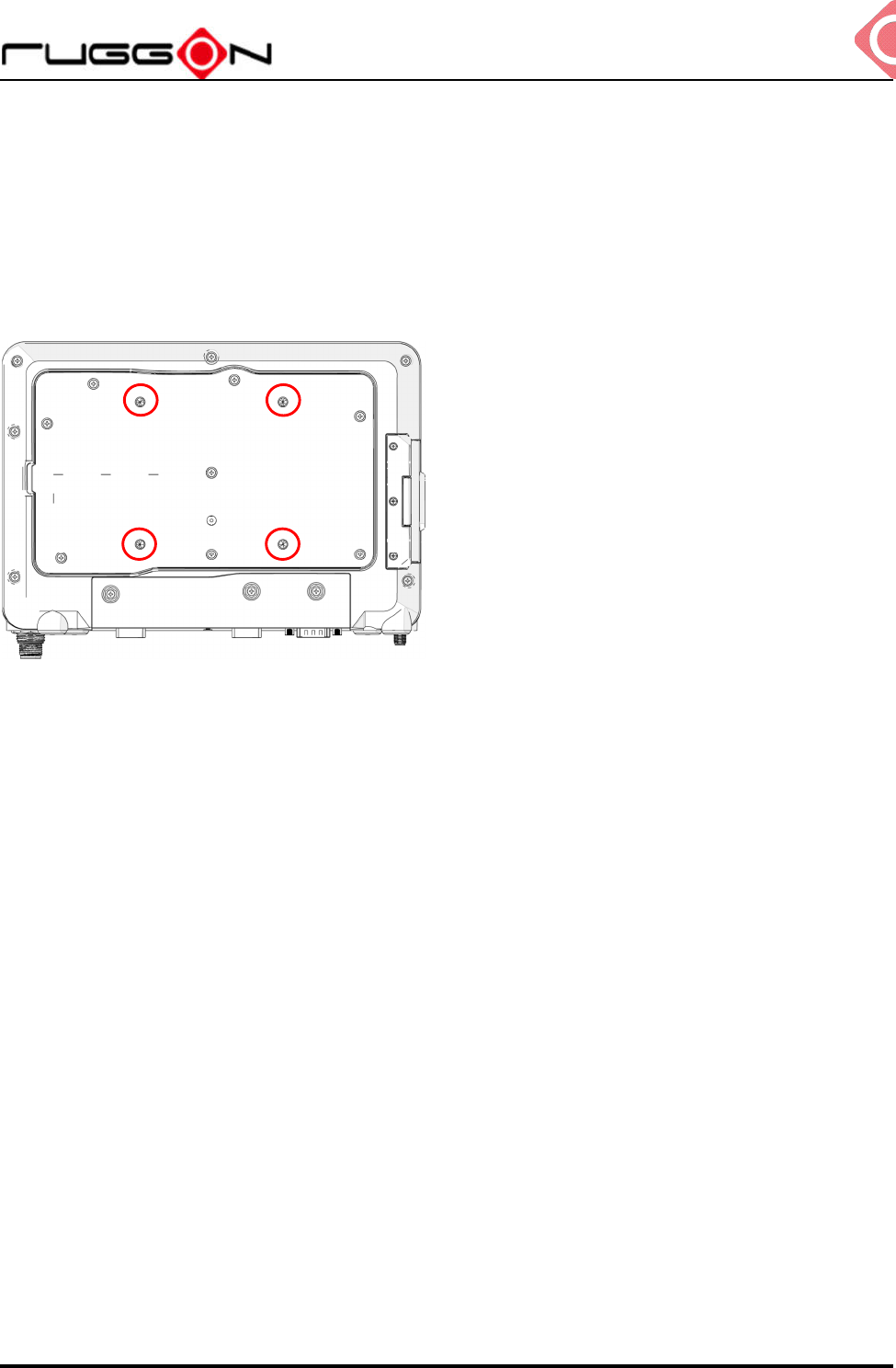
Chapter 2. Hardware Mounting
The MT7010 supports a standard VESA version MIS-D, 75, C (75mm distance quadrate
order, M5 thread, deepness 6mm) through the four drill holes on the back side of the device.
Notes: To prevent any damage or injury, make sure the mounting bracket is securely
attached.
MT7010
V1.0
14
Chapter 3. Start up
Powering the System
Connector Power
MT7010 allows a wide range of DC power input from 9~36V via a 5-pin M12 A-code power
cord. There are two options to start up the MT7010 via car power cable or external power
adapter.
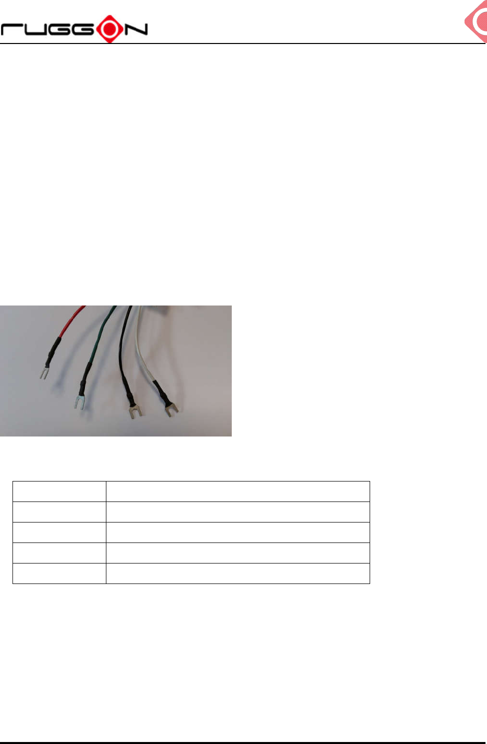
The wire definition.
Wire Color Description
RED V+
BLACK V-
GREEN Chassis Ground
WHITE ACC/ Ignition
Power source from car power cable
1. The bare wire lead cable allows you to directly wire 12 V or 24 V car power supply.
Please follow the wire definition to connect to your power source.
MT7010
V1.0
15
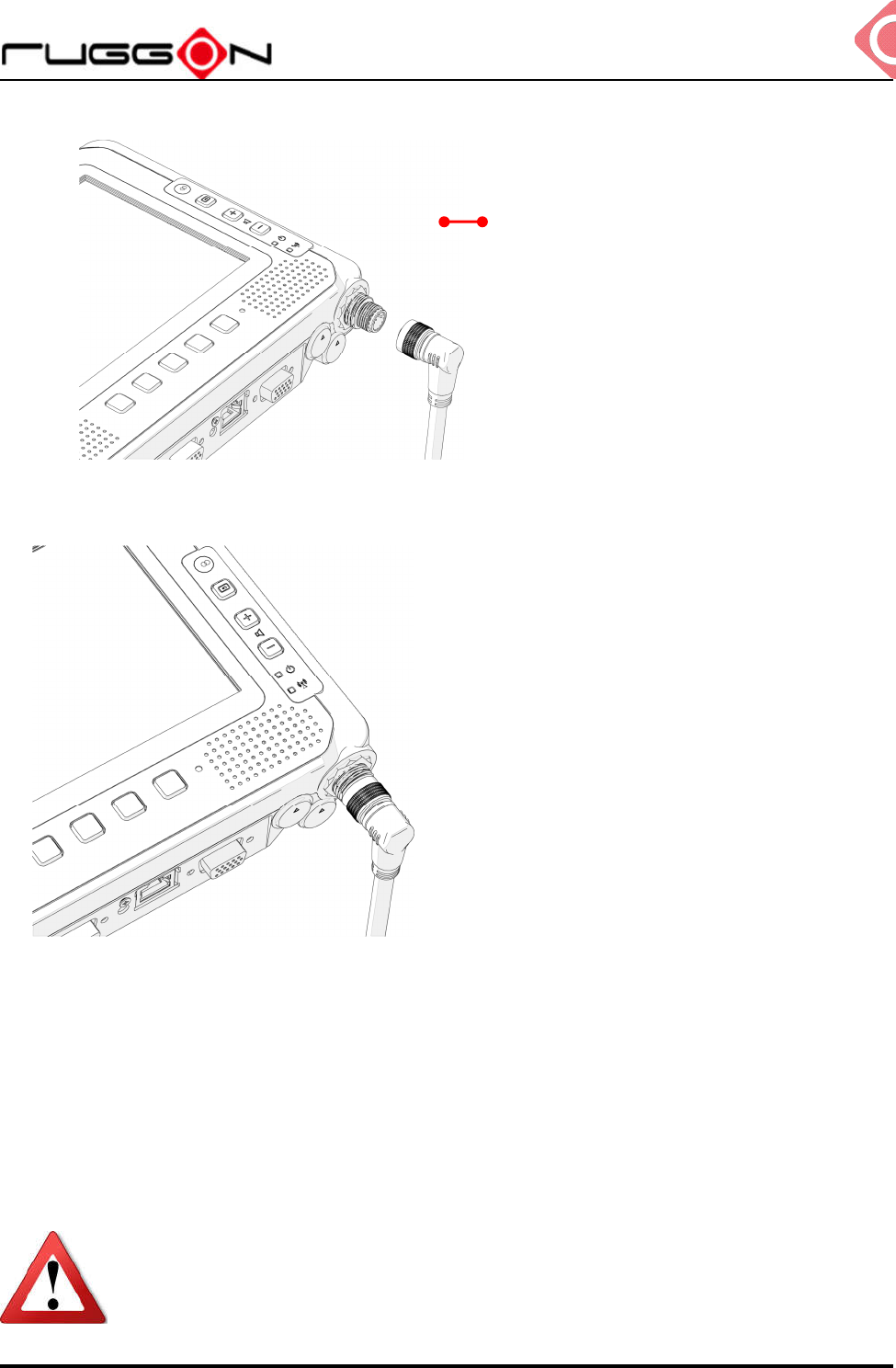
2. Plug the power code into the power connector on the top of the arrow mark.
3. Twist the nut to lock the power connector to the device.
4. MT7010 will turn on automatically when the power supply is connected to the device.
Power source from external power adapter
If your power source is from external power adapter, the mean the power source doesn’t
control by AAC/Ignition signal. Please short red (V+) and white (ACC/ Ignition) wires.
Ensure that the power supplies are disconnected when the power cord
plug into the power connector.
Top of the arrow mark

MT7010
V1.0
16
Powering Down the System
MT7010 will be auto power off after one minute when the power supply is removed. If you
use software to power off the system, please remember to remove the power supply too;
otherwise, the device will auto reboot again.
MT7010
V1.0
17
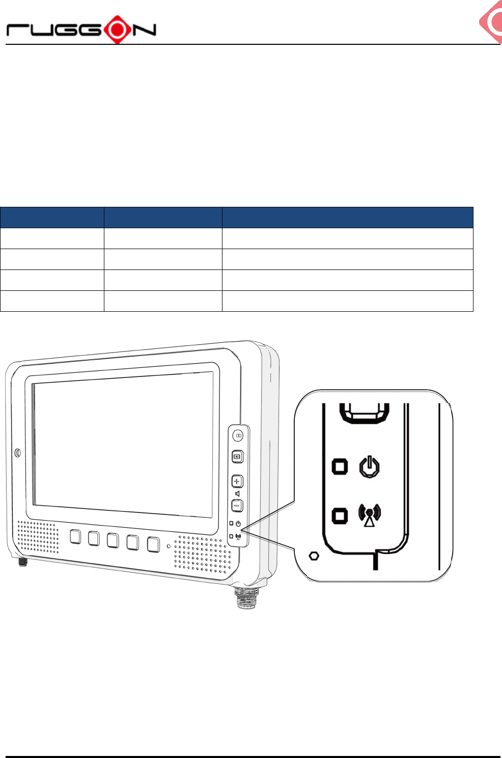
LED Status
The LEDs on MT7010 are status indicators that show the operating status of your system.
The status indicators can help pinpoint possible failed hardware components causing
specific symptoms. There are two status indicators in the front panel. Refer to the
description below.
LED Status Description
PWR Blink Green Power up
PWR. Blink Yellow Load BIOS/ boot loader
PWR Solid Green System ready to use
PWR Blink Red Vehicle battery abnormal
MT7010
V1.0
18
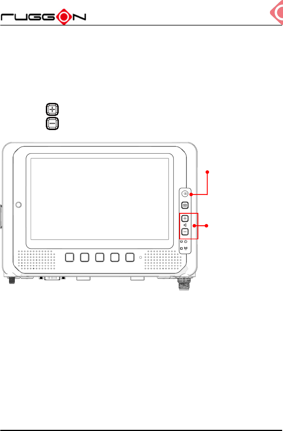
Adjust the Speaker Volume
MT7010 has the volume control buttons to adjust the speakers’ volume; you also can control
the overall level of sound using Windows. When you press the top part of the volume button,
it makes the volume louder; pressing the bottom part makes the volume softer
Press the button to decrease the volume louder.
Press the button to increase the volume softer.
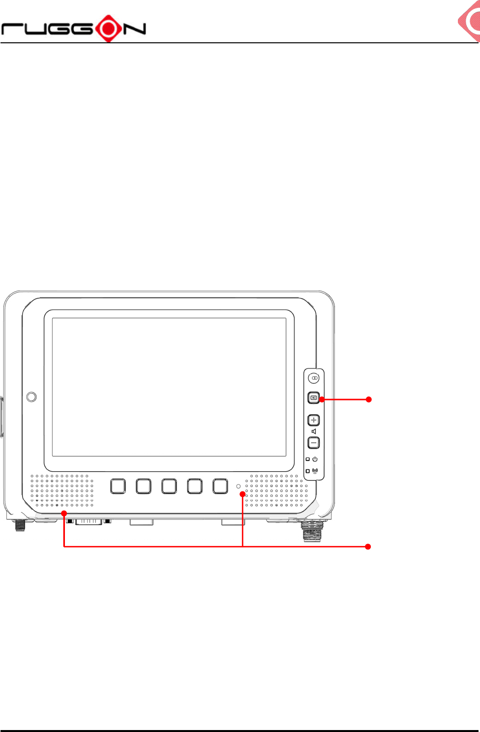
Auto-Brightness Adjustment
When you are using MT7010, you may well encounter different lighting conditions that make
it difficult to see the information on screen. MT7010 is built-in the ambient light sensor on the
front panel to supports auto-dimming, you also can disable this function and manually adjust
the brightness, the setting can be done via DashON.
Volume Control
Ambient light sensor
MT7010
V1.0
19
Internal Microphone
MT7010 equips two internal microphone without the need for an external microphone. In
addition to the built-in speaker and microphones, you can plug external headsets in the
audio jack.
Programmable Buttons
MT7010 provides default commands for five programmable buttons. You can configure the
programmable buttons via DashON to different commands or keyboard shortcuts to better fit
your work style.
Power Management
In additional to setting in Windows Control Panel, MT7010 also provide the utility, DashON,
to set the configuration including power management and system setup. Please refer the
Chapter 6 for configuration setting in DashON.
Display turn on/off
Internal MIC-in
MT7010
V1.0
20
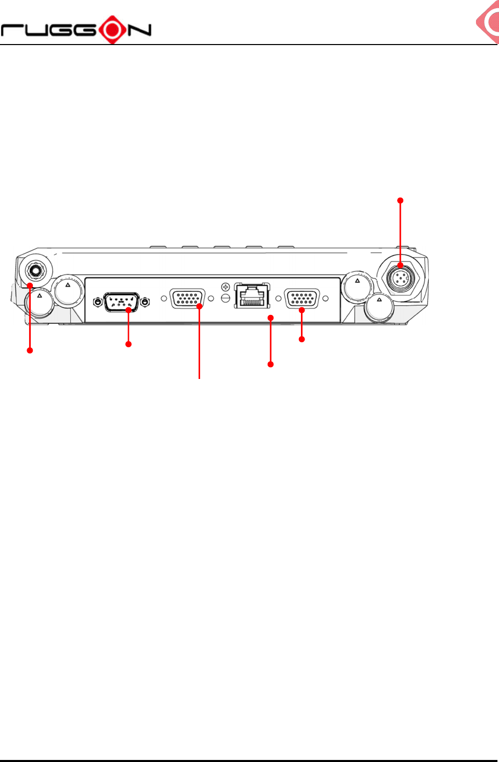
Chapter 4. Jumpers and Connectors
Bottom View
Power Input Connector
GPS Antenna Connector (SMA Jack)
RS-232 with PWR
(COM1)
LAN
GPIO, CANBus
USB, RS-232/422/485 (COM2)
USB 2.0
MT7010
V1.0
21
External Connectors Pin Assignments
Use this section as a reference for the pin assignments of the various ports available on the
MT7010.
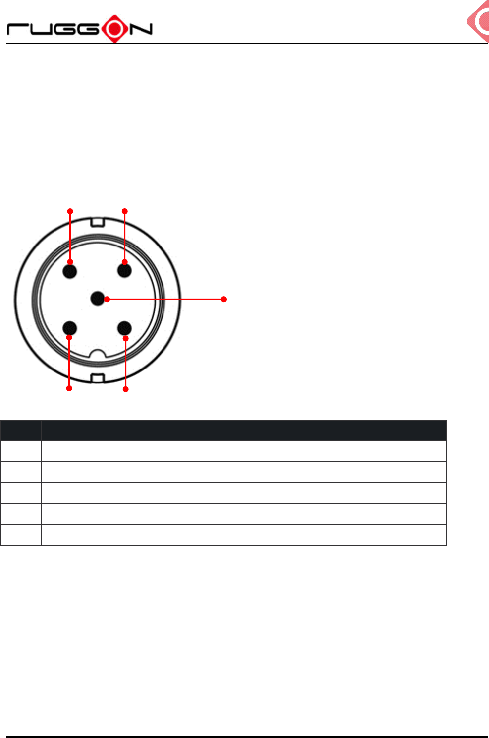
Power Connector
Pin Signal
1 DC+
2
3 GND
4
5 ACC/ Ignition
Note: Please refer the Chapter 4 section 1 for the external power cable to connect to power
source.
1
2
3
4
5
MT7010
V1.0
22
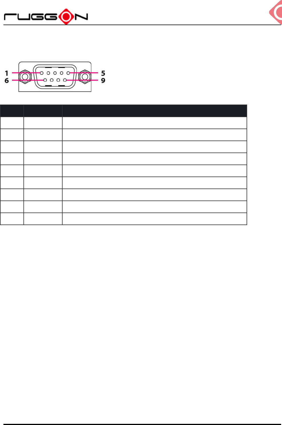
RS-232 Port
Pin Signal Description
1 DCD Data carrier detect (input)
2 RXD Receive data (input)
3 TXD Transmit data (output)
4 DTR Data terminal ready (output)
5 GND Signal/power ground
6 DSR Data set ready (input)
7 RTS Request to send (output)
8 CTS Clear to send (input)
9 RI / PWR Bar code scanner power (1 A max) or Ring indicator (input)
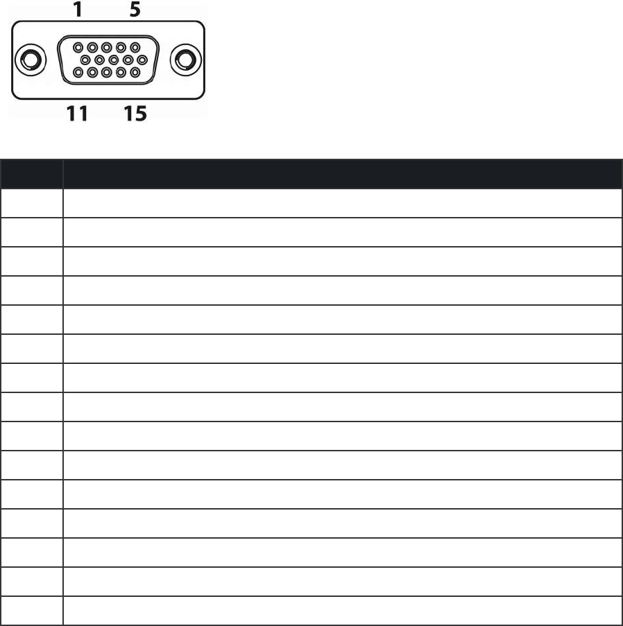
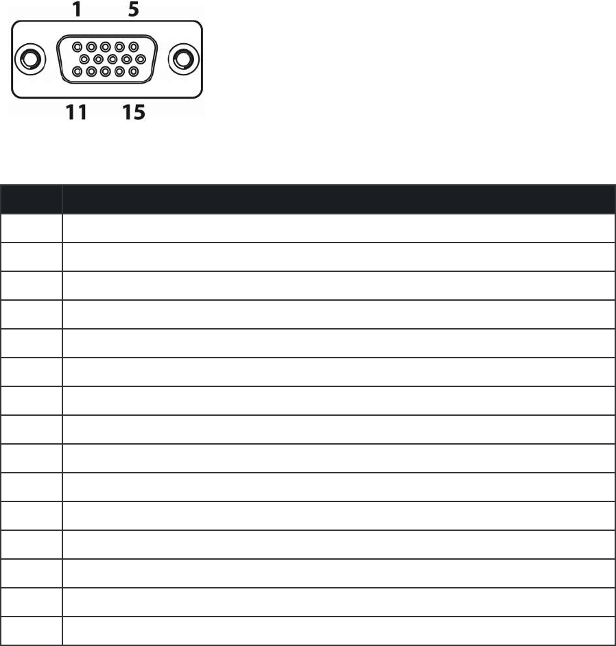
USB and RS-232/422/485 Port
Pin Signal
1 RS-422 TX+
2 RS-422 RX+
3 RS-485 TX+
4 RS-232 TX
5 GND
6 RS-422 TX-
7 RS-422 RX-
8 RS-485 TX-
9 USB 5V
10 RS-232 RX
11 GND
12 USB DP
13 USB DM
14 USB 5V
15 NC
We provide Y-cable with DB15 male connector is the RS232/422/485 and USB converter.
Please contact your local representative for ordering information
GPIO and CANbus Port
Pin Signal
1 CAN_H
2 N/A
3 N/A
4 FWD
5 WHEELTICK
6 CAN_L
7 N/A
8 N/A
9 CARD POWER
10 GND
11 SOS
12 DIO_OUT1 (5V 10mA)
13 DIO_IN1 (5V 100mA)
14 DIO_IN2 (5V 100mA)
15 DIO_OUT2 (5V 10mA)
We provide the DB15 male connector to multiple pins without termination cable. Please
contact your local representative for ordering information