RuggON PM-522 TABLET PC User Manual PM 522 UM D2 08152014x
RuggON Corporation TABLET PC PM 522 UM D2 08152014x
RuggON >
Contents
UserMan_Part 2
Connecting to External Cabling
To prevent damage to the device, connect all cabling and accessories
before powering up the device.
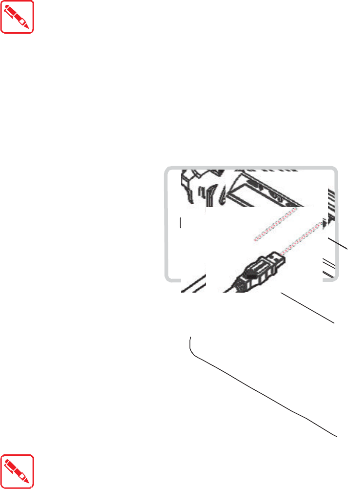
Connect USB Cabling
The PM-522 have two USB ports for connecting USB devices, such as a digital camera,
scanner, printer, modem, and mouse. The USB ports support USB 2.0 or USB 3.0 devices.
1. Open the I/O cover. See “Removing the I/O Cover” on page 22.
2. Connect to USB device via USB cable.
Figure 23. Connect USB Cabling
Connect Ethernet Cabling
The PM-522 provide mini USB to RJ45 dougle for connecting Ethernet.
Use a shielded cable is required to maintain emissions and susceptibility
compliance.
1. Open the I/O cover. See “Removing the I/O Cover” on page 22.
2. Connect the mini USB to RJ45 dongle to micro USB port on the PM-522.
3. Connect LAN cable to mini USB to RJ45 dongle.
Figure 24. Connect Mini USB to RJ45 Dongle
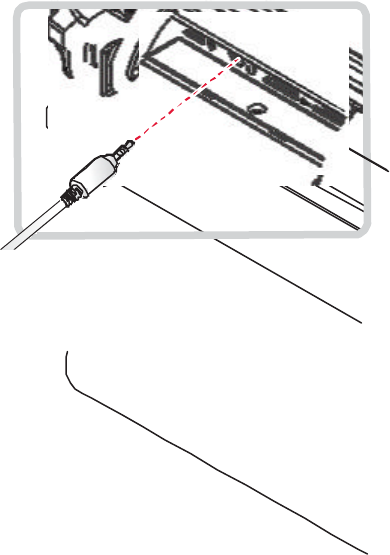
Connect Audio Cabling
For higher audio quality, you can send sound through external audio devices such as
speakers, headphones, or earphone using audio connector.
1. Open the I/O cover. See “Removing the I/O Cover” on page 22.
2. Connect the audio cable.
Figure 25. Connect Audio Cabling
Handstrap and Shoulder Strap
The PM-522 is equipped with a handstrap and a shoulder strap to provide users safety use.
For more information, see “Find Your Configuration Number” on page 62 and “Connecting the
Shoulder Strap” on page 29.
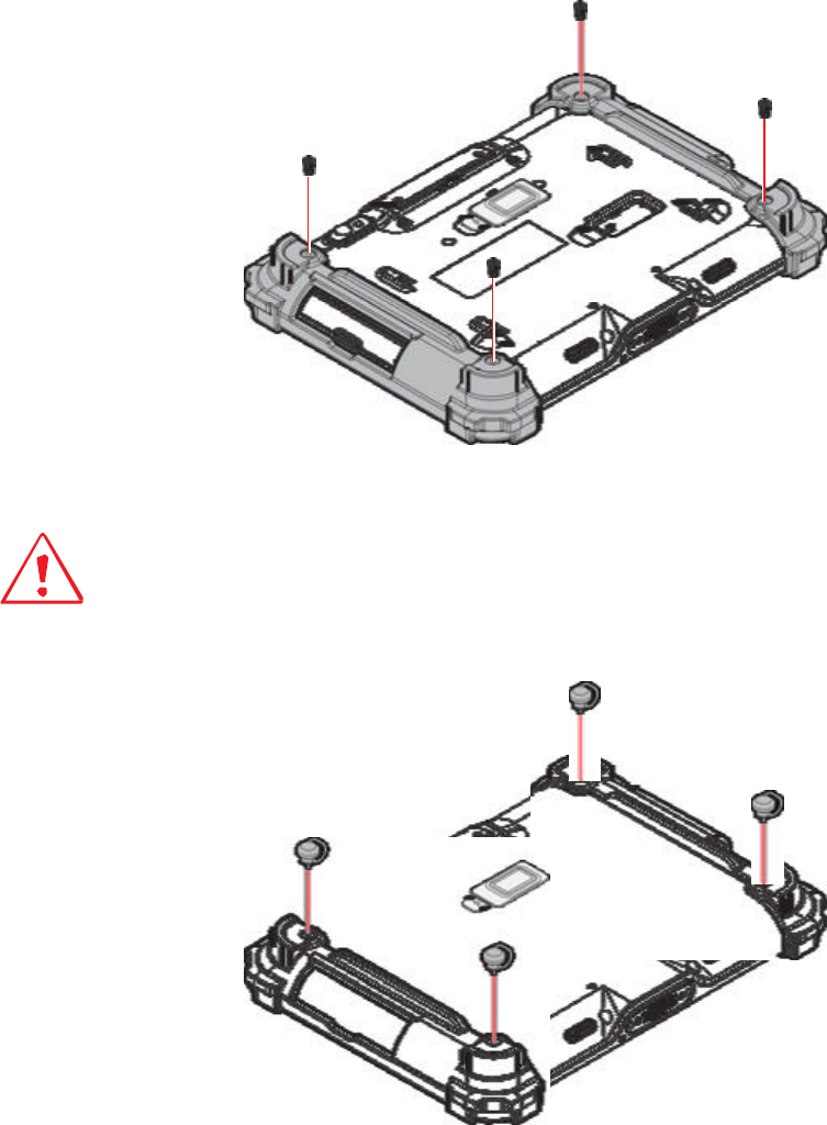
Connecting the Handstrap
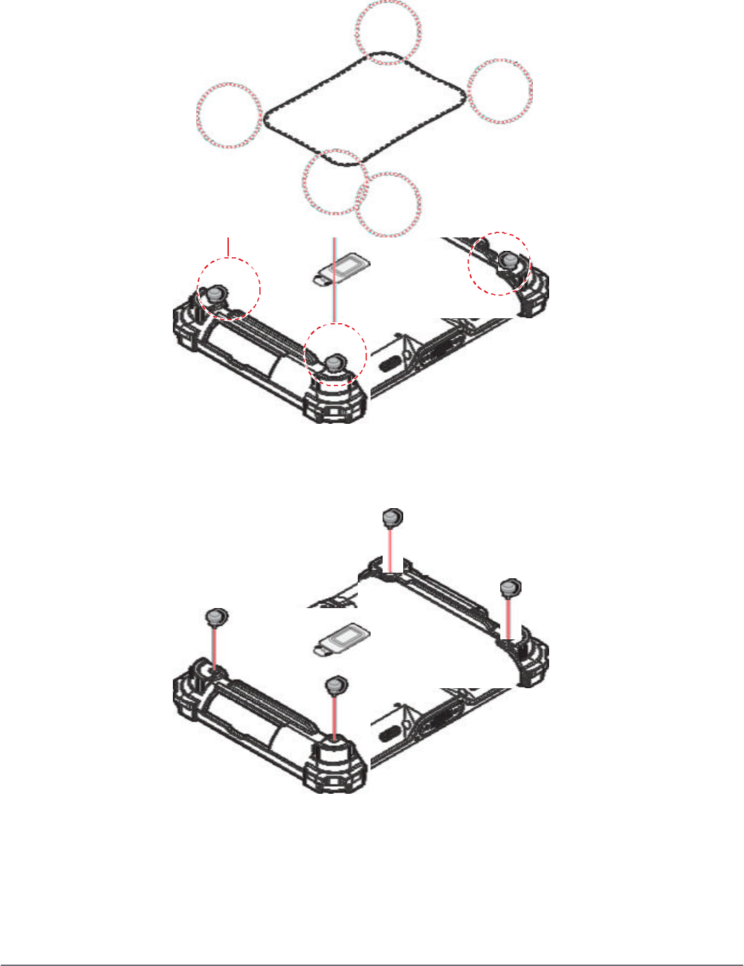
1. Remove the screws securing the bumpers.
Figure 26. Removing the Screws
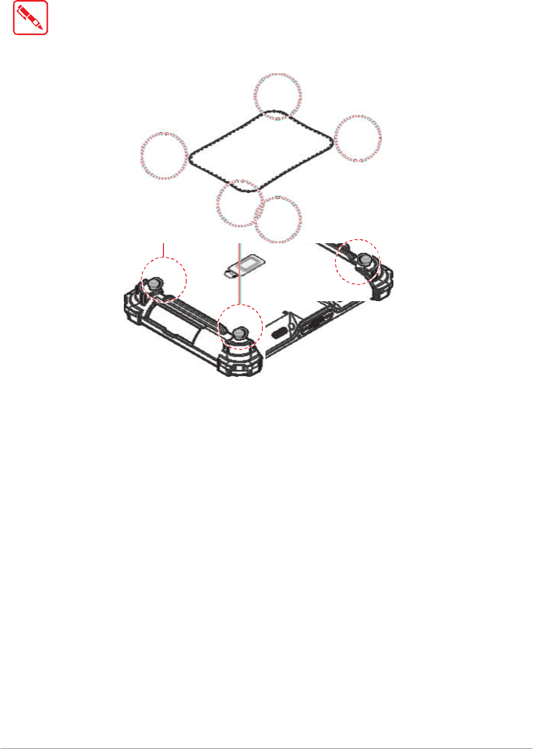
2. Install the D-rings.
Make sure the D-rings are tightly secured before installing the handstrap.
Figure 27. Installing the D-rings
4. Connect to lock the handstrap on the D-rings.
24
Getting Started
When handstrap is installed, the stylus can place with handstrap.
Figure 28. Connecting the Handstrap
25
Getting Started
Removing the Handstrap
1. Unlock the handstrap from the D-rings.
Figure 29. Removing the Handstrap
2. Remove the D-rings.
Figure 30. Removing the D-rings
26