Contents
User manual_Part 1

PM-311B
User's Manual
©2016 RuggON Corporation. All rights reserved.
TRADEMARKS
RuggON logo is a trademark of RuggON Corporation, registered in the United States Patent and
Trademark Ofce and in other countries. Microsoft and the Windows logo are either registered
trademarks or trademarks of Microsoft Corporation in the United States and/or other countries.
Microsoft products are licensed to OEMs by Microsoft Licensing, Inc., a wholly owned subsidiary
of Microsoft Corporation. The Bluetooth® word mark and logos are registered trademarks owned
by Bluetooth SIG, Inc. All other brand and product names are trademarks or registered trademarks
of their respective owners.
Images shown in this document may vary slightly from actual products at time of shipping.
Information in this manual is subject to change without notice.

Table of Contents
About This Manual
Related Information ......................................................................................1
Conventions..................................................................................................1
Basic Safety Guidelines
Intended Use ................................................................................................2
Maintenance and Operation Overview .........................................................2
Safety ...........................................................................................................3
Electrical Hazards.........................................................................................3
Safety Guidelines for Mounting ....................................................................3
Environmental...............................................................................................3
Radio Transmissions ....................................................................................4
Cleaning and Servicing.................................................................................4
Regulatory and Certification .........................................................................4
Lithium Battery Safety Statement .................................................................5
Chapter 1. Introduction
About This Guide ..........................................................................................6
Unpacking the Device...................................................................................6
Technical Specifications ...............................................................................6
PM-311B Configuration Options ...................................................................8
Parts List.......................................................................................................9
Identifying the Device .................................................................................10
Dimensions .................................................................................................15
Touch Screen Features ..............................................................................16
Chapter 2. Getting Started
Charging the Battery...................................................................................18
Powering the Device On and Off ................................................................20
Installing the MicroSD Card ........................................................................25
Removing the MicroSD Card ......................................................................26
Installing on the Vehicle Dock.....................................................................27
Removing from the Vehicle Dock ...............................................................28
i

ii
Installing on the Desktop Dock ...................................................................29
Removing from the Desktop Dock ..............................................................29
Using the Stylus .......................................................................................... 30
Removing the Protective Film from the Display ..........................................30
Chapter 3. Operation
Removing the Snap-on Module Connector Cover ......................................31
Replacing the Snap-on Module Connector Cover ......................................32
Opening the I/O Compartment Cover .........................................................34
Closing the I/O Compartment Cover ..........................................................35
Connecting to External Cabling ..................................................................36
Handstrap, Carrying Handle and Shoulder Strap .......................................38
Installing the External Battery .....................................................................43
Removing the External Battery ...................................................................46
Magnetic Stripe Reader and Barcode Scanner ..........................................49
Connecting to a Wireless Network .............................................................50
Paring the NFC Device ...............................................................................51
Chapter 4. Using BIOS Setup Utility
When to Use the BIOS Setup Utility ...........................................................52
Accessing the BIOS Setup Utility ...............................................................52
Installation an Operating System ................................................................54
BIOS Passwords ........................................................................................56
EC and BIOS ..............................................................................................58
Chapter 5. Using the DashON Utility
Overview ..................................................................................................... 63
Chapter 6. Troubleshooting
Troubleshoot the Wi-Fi Connection ............................................................65
Troubleshoot Operating the Computer .......................................................66
Call Product Support ..................................................................................66
Chapter 7. Maintenance
Cleaning the Device ...................................................................................67
Returning the Device ..................................................................................67
Contacting RuggON ...................................................................................67
1
About This Manual
The PM-311B User’s Manual provides instruction for qualied personnel to follow when setting up
a new PM-311B device.
This document is intended for use by qualied personnel to compliment the training and expertise,
not to replace it.
Related Information
Current information and manuals are available for download at the following website:
http://www.ruggon.com
Conventions
Bolded or underlined text is used to emphasize the designated information.
A Note is used to provide additional information for the device or settings.
A Caution is used to warn against potential hazards or to caution against unsafe practices.
A Warning is used to identify immediate hazards for property damage, injury or death.

2
Basic Safety Guidelines
The following safety guidelines are intended to help protect the user from injury and prevent
damage to the hardware.
Do not place anything on the AC adapters power cable and make sure the cable is not
located where it can be tripped over or stepped on.
Do not cover the AC adaptor as it reduces the cooling
Do not use the AC adapter while it is inside the carrying case.
Use only the AC adapter, power cord, and batteries that are approved for use with the device.
Use of another type of battery or AC adapter may cause risk of re or explosion.
If you use an extension cable with the AC adapter, ensure that the total ampere rating of
all products plugged in to the extension cable does not exceed the ampere rating of the
extension cable.
If the device is moved between environments with very different temperature and/ or humidity
ranges, condensation may form on or within the device. Avoid damaging the device by
allowing sufcient time for the moisture to evaporate before using the device.
When disconnecting cables, pull on the connector or on its strain relief loop, not on the
cable itself. When pulling out or plugging in the connector, keep it evenly aligned to prevent
bending the connector pins.
Intended Use
The PM-311B rugged tablet is equipped with multi-functional terminals for stationary and mobile
applications in industrial environments such as logistics, warehousing, eet management,
manufacturing and the automotive industry.
Read the safety guidelines thoroughly before starting any servicing on the device. Read the
guidelines before powering up the device, and keep this document for later use.
The operator is solely responsible for any damage resulting from unauthorized modications to the
device.
Unintended Application Use
The device is not designed for use in life-support systems or critical safety/security systems where
system malfunction can lead to the direct or indirect endangerment of human life. The operator is
fully responsible for using the device in these situations.
Maintenance and Operation Overview
The PM-311B is designed and manufactured according to strict controls and following the stated
safety regulations. The following list identies incorrect operating uses of the PM-311B. Incorrect
use of the PM-311B can lead to hardware damage, safety issues and possible risk to personnel
health:
The PM-311B is under operation by untrained personnel;
The PM-311B is not maintained as recommended;
The PM-311B is not used as intended.

3
Safety
To prevent injury and damage, read the following safety guidelines prior to operating the
device. The manufacturer assumes no liability for any and all damages arising from misuse or
noncompliance with these guidelines.
Electrical Hazards
Cleaning/Servicing: Power Off the PM-311B
Disconnect the PM-311B from power before cleaning or servicing it.
Power Adapter
Contact an authorized service personnel for repairs to the power pack. In the event of a blown
fuse after replacing the fuse, contact an authorized service personnel to avoid electrical shock.
Use only Supplied Power Cables
RuggON power cables meet industrial requirements for low-temperature exibility, UV resistance,
and oil resistance. Use only supplied power cables from RuggON.
If other power cables are used, the following may apply:
The operator is solely responsible for the resulting damage;
All RuggON warranties are void.
Environmental Hazards
Do not use the PM-311B in locations near/with ammable gases or vapor.
The use of electrical equipment in explosive environments can be dangerous.
Turn off the device when near a gas station, fuel depot, chemical plant or a place where
blasting operations take place.
Safety Guidelines for Mounting
If the PM-311B is installed on a mounting bracket, make sure all mounting equipment meets
with safety and regulatory standards to prevent damage to the hardware or injury.
If installing in a xed location, it is adviced to properly secure the device to prevent loss of the
device.
Environmental
Ambient Temperature
The PM-311B operates on the basis of a passive cooling concept which internal waste heat is
released via the housing surface and requires fresh airow in the environment.
Operating the PM-311B with no fresh cooling air may cause overheating and damage to the
device.
The operating environment should not be enclosed to prevent the cool air being heated by
the heat waste from the device.

4
Connecting and Disconnecting External Devices
To prevent the considerable damage, the PM-311B and the external device should be
disconnected from power when connecting/disconnecting excluding USB devices.
Only Use Authorized Accessories
Only use the supplied cables, power packs and other accessories that have been tested and
approved by RuggON. Contact your local distributor for further information.
Radio Transmissions
Permitted Transmission Power
Follow the national regulations for the maximum permitted transmission power.
The operator is solely responsible for this type of operation.
Radio Frequency Limited Locations
Considering the radio frequency limitation in hospitals and aircraft, the PM-311B can only be
installed with permission.
Industrial computers may affect the function of implanted medical devices such as pacemakers
and may cause malfunction.
Cleaning and Servicing
Disconnect the PM-311B from power before cleaning or servicing.
Never clean the PM-311B with compressed air, a pressure washer or a vacuum cleaner.
If necessary, clean the housing of the PM-311B with a damp cloth.
Clean the touch-screen with a nonabrasive cloth.
Regulatory and Certication
FCC
This equipment has been tested and found to comply with the limits for a Class B digital device,
pursuant to part 15 of the FCC Rules. These limits are designed to provide reasonable protection
against harmful interference when the equipment is operated in a commercial environment.
This equipment generates, uses, and can radiate radio frequency energy and, if not installed
and used in accordance with the instruction manual, may cause harmful interference to radio
communications. Operation of this equipment in a residential area is likely to cause harmful
interference in which case the user will be required to correct the interference at his own expense.
However, there is no guarantee that interference will not occur in a particular installation. If
this equipment does cause harmful interference to radio or television reception, which can be
determined by turning the equipment off and on, the user is encouraged to try to correct the
interference by one or more of the following measures:
Reorient or relocate the receiving antenna.
Increase the separation between the equipment and receiver.
Connect the equipment into an outlet on a circuit different from that to which the receiver is
connected.

5
■ Consult the dealer or an experienced radio / TV technician for help.
Any changes or modifications not expressly approved by the grantee of this device could void the user¡s
authority to operate the equipment.
This device is operation in 5.15 ¡ 5.25GHz frequency range, then restricted in indoor use only, Outdoor
operations in the 5.15 ¡ 5.25GHz is prohibit.
This device is slave equipment; the device is not radar detection and not ad-hoc operation in the DFS
band.
Labeling Requirements
This device complies with Part 15 of the FCC Rules. Operation is subject to the following two
conditions: (1) this device may not cause harmful interference, and (2) this device must accept any
interference received, including interference that may cause undesired operation.
RF Exposure Information (SAR)
This device meets the government¡s requirements for exposure to radio waves. This device is
designed and manufactured not to exceed the emission limits for exposure to radio frequency (RF)
energy set by the Federal Communications Commission of the U.S. Government.
The exposure standard employs a unit of measurement known as the Specific Absorption Rate,
or SAR. The SAR limit set by the FCC is 1.6 W/kg. Tests for SAR are conducted using standard
operating positions accepted by the FCC with the EUT transmitting at the specified power level in
different channels.
The highest SAR value for the device as reported to the FCC is 1.487 W/kg when placed next to
the body.
CE Marking
This product has passed the CE test for environmental specifications when shielded cables are
used for external wiring. We recommend the use of shielded cables. Please contact your local
representative for ordering information.
This product has passed the CE test for environmental specifications. Test conditions for passing
included the equipment being operated within an industrial enclosure. In order to protect the
product from being damaged by ESD (Electrostatic Discharge) and EMI leakage, we strongly
recommend the use of CE-compliant industrial enclosure products.
R&TTE
This device complies with the essential requirements of the R&TTE Directive 2014/53/EU.
CB
This device complies with the IEC 60950-1:2005 (second edition)+Am1:2009+Am2:2013.
Lithium Battery Safety Statement
Lithium battery inside. Danger of explosion if battery is incorrectly replaced. Replace only with same or
equivalent type recommended by battery manufacturer.

6
Introduction
Chapter 1. Introduction
The PM-311B is a rugged device equipped with 802.11, Bluetooth and GNSS for wireless data
communications.
The PM-311B is a rugged 7” tablet computer capable of 1024 x 600 resolution.
The PM-311B supports the following operating systems:
Windows® 10 IoT Enterprise for Small Tablets 64bits
Windows® Embedded 8.1 Industry Pro Tablet 64bits
Windows® Embedded Standard 8 64bits
About This Guide
The PM-311B User Manual provides instruction for qualied personnel to use as a guide for setup
of the device. This document is not intended to replace the training and expertise of the end-user.
Unpacking the Device
Before you begin the installation or conguration process make sure to inspect all components
and accessories. Contact your representative if there are any missing or damaged items. See
“Contacting RuggON” on page 67.
Technical Specications
Table 1. Technical Specications
Item Description
Display 7” LED Backlight, 1024 (W) x 600 (H)
Touch screen 5-point capacitive touch screen
Brightness 800 nits
CPU Intel® Celeron® Processor N2930
Operating System
(Optional)
Windows® 10 IoT Enterprise for Small Tablets 64bits
Windows® Embedded 8.1 Industry Pro Tablet 64bits
Windows® Embedded Standard 8 64bits
RAM DDR3L@1600 MHz 4 GB RAM (optional: 8 GB)
Storage M.2 SSD 128 GB (optional: 256 GB)
Battery
Standard battery: 7.5V, 2900mAh, Li-ion
Extended hot swappable battery: 7.4V, 4200 mAh, Li-ion
(optional)
Power Supply AC 100V ~ 240V, 50~60Hz input; 19VDC@3.42A, 65W
Dimensions (W x H x L) 225 mm (8.86”) x 27 mm (1.06”) x 168 mm (6.61”)
Weight 950 g (2.09 lbs)

Introduction
Item
Description
Wireless
WLAN
Wi-Fi IEEE 802.11 a/b/g/n/ac
Bluetooth
Bluetooth V4.0
Sensor
Sensor
Gyroscope, G Sensor, E-compass, Light Sensor
I/O
Docking Connector
32-pin
DC-IN Jack
x1
MicroSD Slot
x1
Audio Jack
x1; headphone / microphone combo
USB 3.0
x2; type A
RS-232
x1
Ethernet
x1
Security
TPM
TPM 2.0
Data Collection
Camera
■
Front: 2.0 Mega-Pixels camera
■
Rear: 8.0 Mega-Pixels camera with LED auxiliary light and
Auto-focus
GNSS
YES
NFC
YES
Fingerprint Reader
Optional
Magnetic Stripe Reader +
2D Barcode
Optional
Magnetic Stripe Reader +
MRZ
Optional
7

Introduction
Item
Description
Rugged Specifications
Drop
153 cm (5 feet), 26 drops on plywood
MIL-STD 810G
■ Vibration (MIL-STD-810G Method 514.6 Category 4,
Fig 514.6C-1, Fig 514.6C-2, Fig 514.6C-3)
■
Drop (MIL-STD-810G Method 516.6 Procedure IV)
■
Mechanical shock
(MIL-STD-810G Method 516.6 Procedure I, Procedure V)
■
Operation and storage temperature
(MIL-STD-810G Method 501.5 and 502.5)
■
Humidity MIL-STD-810G Method 507.5 Humidity Procedure II
Aggravated Cycles (Fig 507.5-7)
IP rating
IP65
Operating Temperature
Range
-20°C (-4°F) to 50°C (122°F)
Storage Temperature
Range
-30°C (-22°F) to 70°C (158°F)
Humidity
5-95% without condensation
PM-311B Configuration Options
The following options are available for the PM-311B:
■
MSR+Barcode reader
■
MSR+MRZ reader
■
High capacity battery
8
9
Introduction
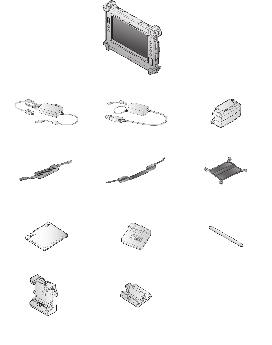
Parts List
The PM-311B is shipped with the following items. All other accessories are sold and ordered
separately. For help, contact your local RuggON sales representative. See “Contacting RuggON”
on page 67.
PM-311B
Power Adapter Car Adapter* Magnetic Stripe Reader with
2D Barcode*
2-Point Carrying Handle 2-Point Shoulder Strap 4-Point Handstrap with
Hitch D-rings
(Attaching straps)
External Battery* Battery Charger* Stylus
Vehicle Dock* Desktop Dock*
*Optional, not included in the standard package.
10
Introduction
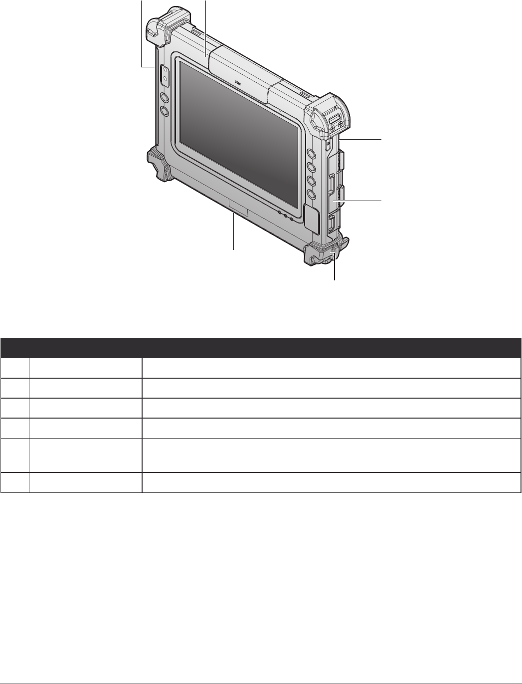
Identifying the Device
Overview
1
5
3
4
6
2
Figure 1. Overview
Table 2. Overview
No Item Description
1Left view See “Side View” on page 13 for further information.
2Front view See “Front View” on page 11 for further information.
3Rear view See “Rear View” on page 14 for further information.
4Right view See “Side View” on page 13 for further information.
5Rubber bumpers Easy to grip rubber bumpers enable the rugged tablet to withstand
shocks and drop for use in demanding environments.
6Bottom view See “Bottom View” on page 12 for further information.
11
Introduction
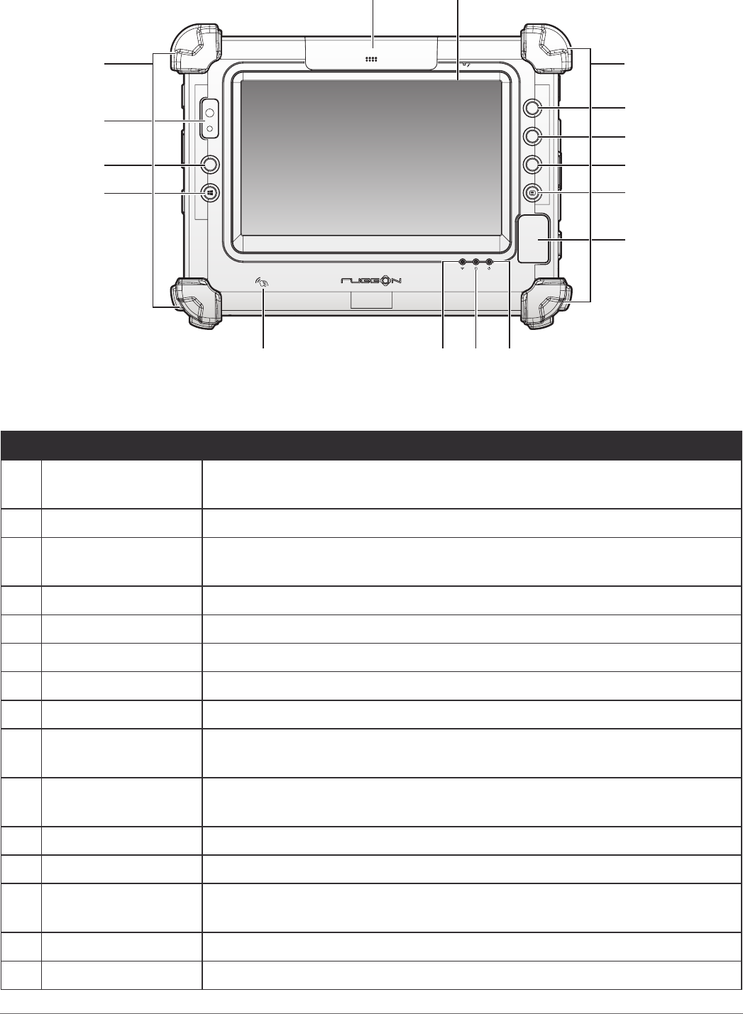
Front View
P4
P2
P3
P1
14
13
15 4
5
6
7
8
1
10 91112
2
3 3
Figure 2. Front View
Table 3. Front View
No Item Description
1Snap-on module
connector cover Open to access snap-on module connector.
2Touch screen Capacitive touch panel.
3Rubber bumpers Easy to grip rubber bumpers enable the rugged tablet to withstand
shocks and drop for use in demanding environments.
4P1 key Programmable function key.
5P2 key Programmable function key.
6P3 key Programmable function key.
7Menu key Enter DashON function.
8Fingerprint sensor Read ngerprint for biometric authentication.
9Power LED The LED lights when the device is on or when the battery is being
charged.
10 Storage Access
LED The LED (blue) lights during access of system storage drive.
11 Wi-Fi LED The LED lights to indicate Wi-Fi is enabled.
12 NFC sensor Pairing with NFC devices or reading RFID cards.
13 Start key Windows® Start key (also can trigger BIOS setup and work as enter
button in BIOS mode).
14 P4 key Programmable function key.
15 Front camera 2 Mega-Pixels camera.
12
Introduction
LED Status
Table 4. LED Status
Item Status Description
Power
Green: On Power on / not charging
Green: Blinking Battery charging
Amber: On Low battery
Storage
Access
Green: On The system is accessing storage drive
Green: Off The system is not accessing storage
Wi-Fi Green: On Wi-Fi is enabled
Off Wi-Fi is disabled
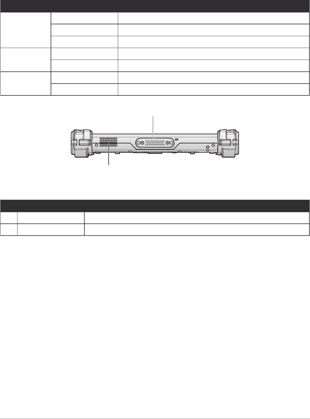
Bottom View
1
2
Figure 3. Bottom View
Table 5. Bottom View
No Item Description
1Docking connector 32 pin connector for docking onto a station.
2 Speaker 1 x 1W waterproof, front mounted speaker.
Introduction
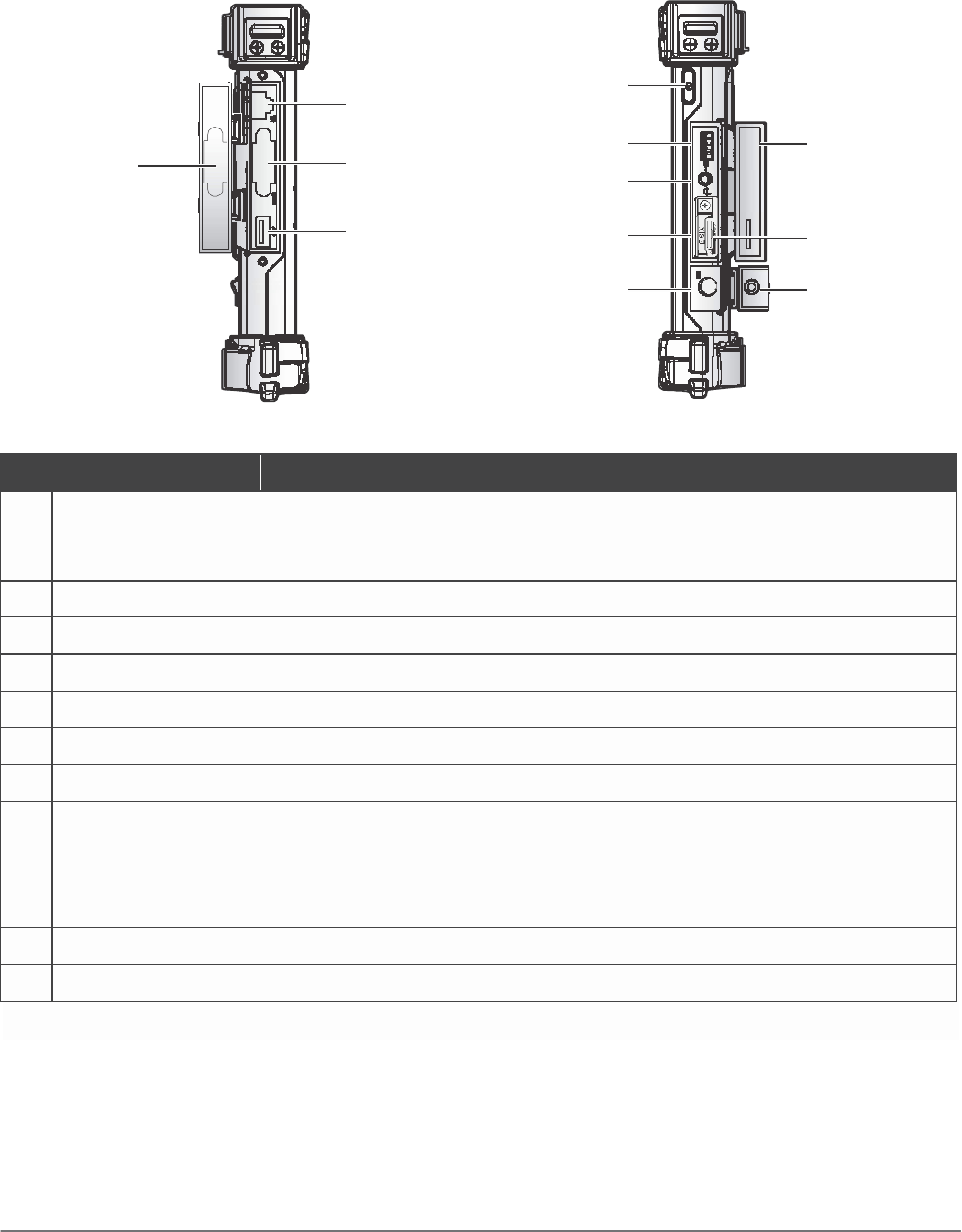
Side View
Left view
Right view
2 5
1 3 6 10
7
4 8 11
9 12
Table 6. Side
V
iew
Figure 4. Side Views
No
Item Description
1 Left I/O
compartment
cover
Open to access the left I/O ports.
2 LAN Connect the PM-311B to an Ethernet interface.
3 RS-232 Connect the PM-311B to a serial device.
4 USB 3.0 Connect USB devices to the PM-311B.
5 Power key Turns the PM-311B on or off.
6 USB 2.0 Connect USB devices to the PM-311B.
7 Audio jack Connect a headphones or external microphone.
9 DC-IN jack Insert power connector to charge battery.
10
Right I/O
compartment
cover
Open to access the right I/O ports.
11
MicroSD slot Insert microSD card in to slot.
12
DC-IN cover Open to access the DC-IN jack.
13
14
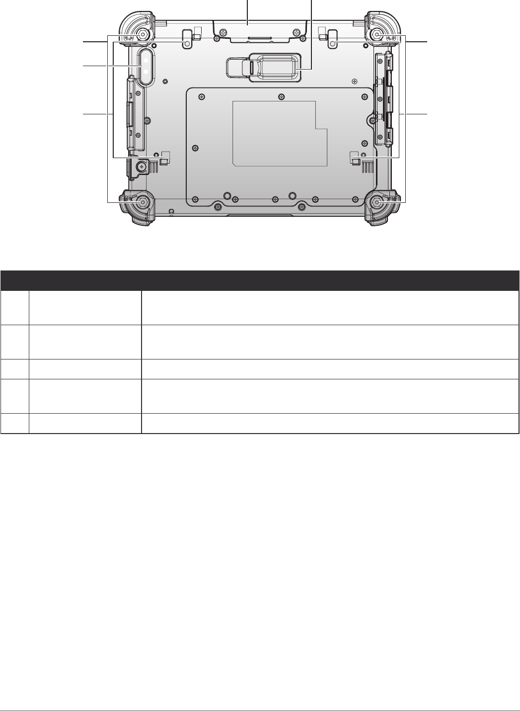
Introduction
Rear View
3
4
21
5
3
4
Figure 5. Rear View
Table 7. Rear View
No Item Description
1Snap-on module
connector cover Open to access snap-on module connector.
2External battery
connector cover
Open to access external battery connector. The external battery is
optional.
3Securing holes Location of holes to secure the handstrap.
4External battery
bracket slots Align with the external battery bracket when installing.
5Rear camera 8.0 Mega-Pixels camera with LED auxiliary light.
15
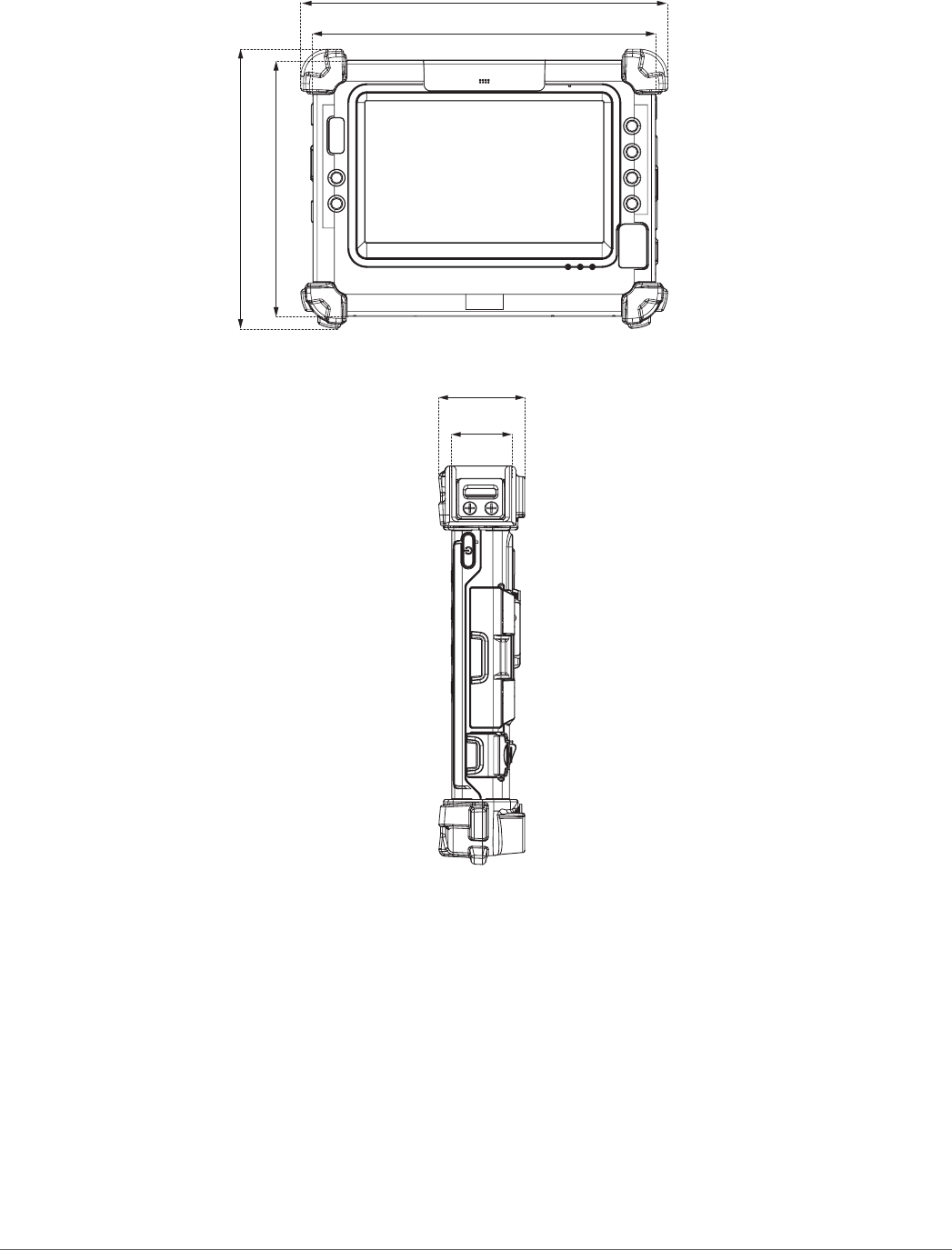
Introduction
Dimensions
The following image lists the device dimensions without add-ons (mm/inches).
240.79 / 9.48
225.00 / 8.86
183.60 / 7.23
168.00 / 6.61
Figure 6. Front View Dimensions
26.50 / 1.04
40.00 / 1.57
Figure 7. Side View Dimensions

16
Introduction
Touch Screen Features
Always use the point of the stylus for clicking or making strokes on the touch screen.
Never use an actual pen, pencil, or sharp/abrasive object on the touch screen.
The stylus is used as if it were a pen or pencil. Touch the screen with the tip of the stylus then
remove the stylus from the screen.
After each use, replace the stylus in the stylus holder for proper care and to preserve the life of the
stylus.
Using a stylus is similar to moving the mouse pointer then left-clicking icons on a desktop
computer screen.
The following actions are available through the use of the stylus:
Open applications
Choose commands in menu
Select options in dialog box or drop-down menu
Drag the scroll bar
Drag across the text to select content
Place the cursor in a text box before typing
A right click is generated by tapping the mouse icon in the system tray. After tapping, the mouse
icon highlights the right button of the icon in red. The next touch screen tap is treated as a right
click. The mouse icon returns to the left button highlighted in red so subsequent taps are treated
as left clicks.
A stylus replacement kit is available.
To prevent damage or malfunction, always dry the touch screen when wet.

17
18
Getting Started
Chapter 2. Getting Started
This section provides an outline of the steps necessary to setup a new PM-311B. A detailed guide
follows the listed items, see as follows.
For additional technical assistance, contact your RuggON representative. See “Contacting
RuggON” on page 67.
It is recommended to installing or remove accessories on a clean, well-lit work
surface. To protect yourself and the device from electrostatic discharge, wear anti-
static wrist straps or place the device on an anti-static mat.
Charging the Battery
When you use the AC adapter to connect your PM-311B to a power outlet, the standard and
external (optional) battery will automatically begin to recharge.
While the battery is charging, the power LED will be active. When the battery is fully charged, the
power LED is lit a solid green.
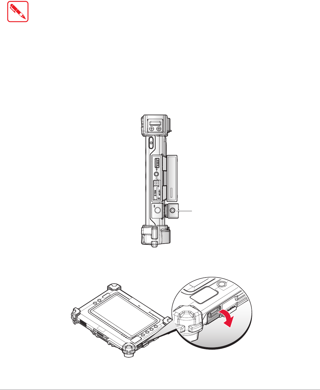
1. Locate the DC-IN cover.
Right view
DC-IN Cover
Figure 8. Right View: Locating the DC-IN Cover
2. Flip open the DC-IN cover to expose the DC-IN jack.
Figure 9. Opening the DC-IN Cover
19
Getting Started
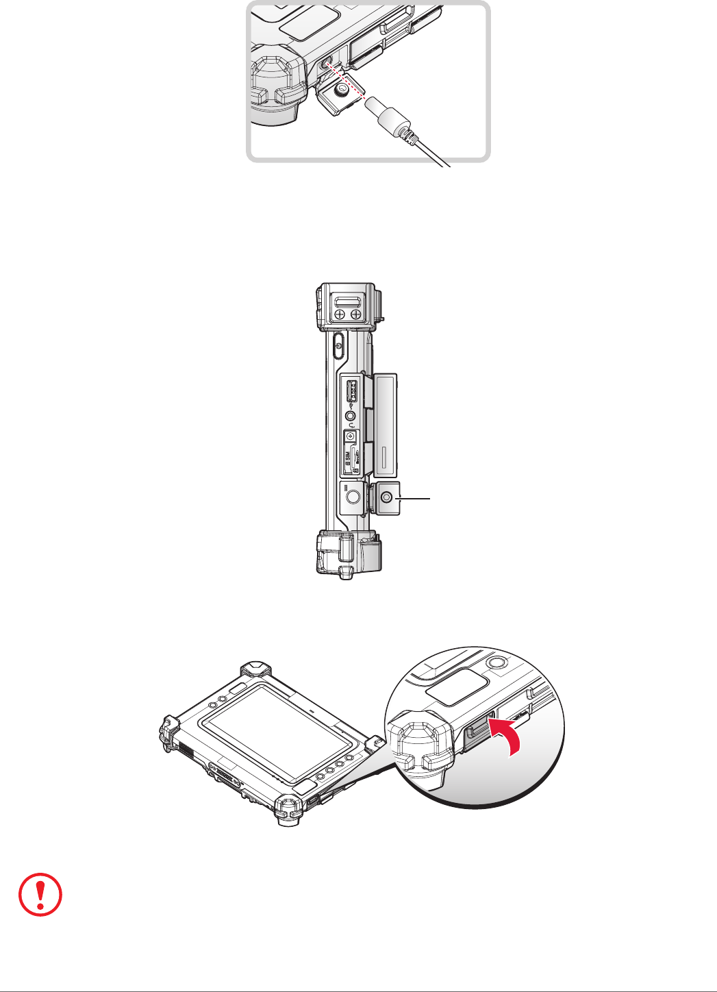
3. Connect the AC adapter to the DC-IN port.
Figure 10. Connecting the AC Adapter
After charging the battery, disconnect the AC adapter and close the DC-IN cover.
1. Locate the DC-IN cover.
Right view
DC-IN Cover
Figure 11. Right View: Locating the DC-IN Cover
2. Flip the DC-IN cover and install.
Figure 12. Closing the DC-IN Cover
The DC-IN cover must be inserted correctly to prevent internal damage to the device.
20
Getting Started
Powering the Device On and Off
Powering On the Device
Only power on the PM-311B after connecting all of the peripherals and cabling.
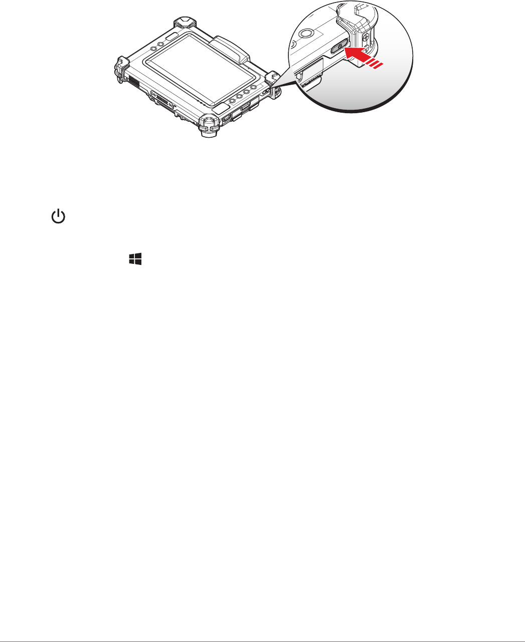
1. Press and hold the power button until the screen lights. The device runs through the start up
sequence and powers up.
Figure 13. Power On the PM-311B
Powering Off the Device
Start screen:
Tap > Shut down.
Desktop screen:
1. Tap and hold at the bottom left corner of the Desktop screen.
2. Tap Shut down or sign out > Shut down.
Both Start screen and Desktop screen:
1. Display charm bar and tap Settings.
2. Tap Power > Shut down.
25
Getting Started
Installing the MicroSD Card
The device supports microSD card for easier data storage.
1. Open the right I/O compartment cover. See “Opening the I/O Compartment Cover” on page
34.
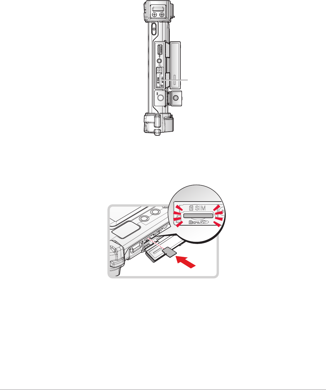
2. Locate the microSD slot in the right I/O parts.
Right view
MicroSD Slot
Figure 22. Right View: Locating the MicroSD Slot
3. The microSD card has a beveled edge. Align the microSD card with the slot making sure that
the corners match.
4. Insert the microSD card and press it in until an audible click sounds.
Figure 23. Installing the MicroSD Card
5. Close the right I/O compartment cover. See “Closing the I/O Compartment Cover” on page
35.
26
Getting Started
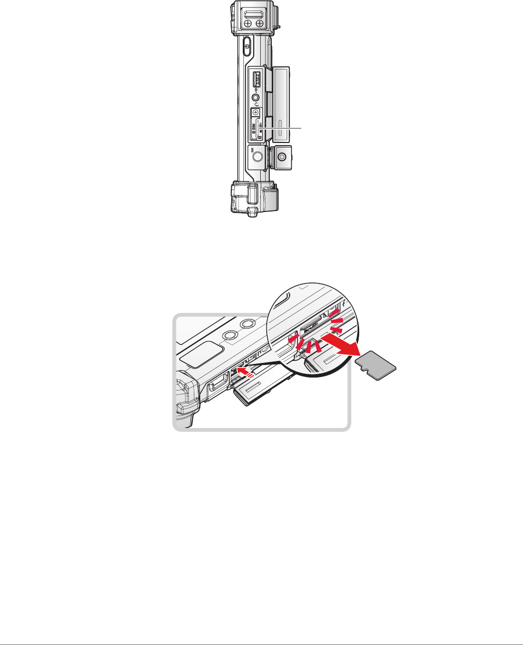
Removing the MicroSD Card
1. Open the right I/O compartment cover. See “Opening the I/O Compartment Cover” on page
34.
2. Locate the microSD slot in the right I/O parts.
Right view
MicroSD Slot
Figure 24. Right View: Locating the MicroSD Slot
3. Press the microSD card in and release it. The card springs out.
4. Grasp the microSD card and remove it from the slot.
Figure 25. Removing the MicroSD Card
5. Close the right I/O compartment cover. See “Closing the I/O Compartment Cover” on page
35.
27
Getting Started
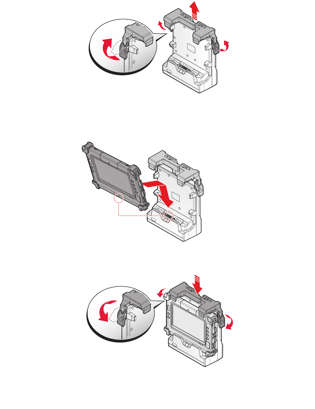
Installing on the Vehicle Dock
1. Power off the PM-311B. See “Powering Off the Device” on page 20.
2. Flip the levers upward on the both sides.
Figure 26. Releasing the Levers
3. Align the docking connector on the PM-311B with the connector on the vehicle dock and
push downward.
4. Push the PM-311B forward and make sure it xed with latches.
Figure 27. Installing the PM-311B
5. Press down the levers at the same time to lock.
Figure 28. Installing the PM-311B
6. Connecting the cabling to the vehicle dock.
28
Getting Started
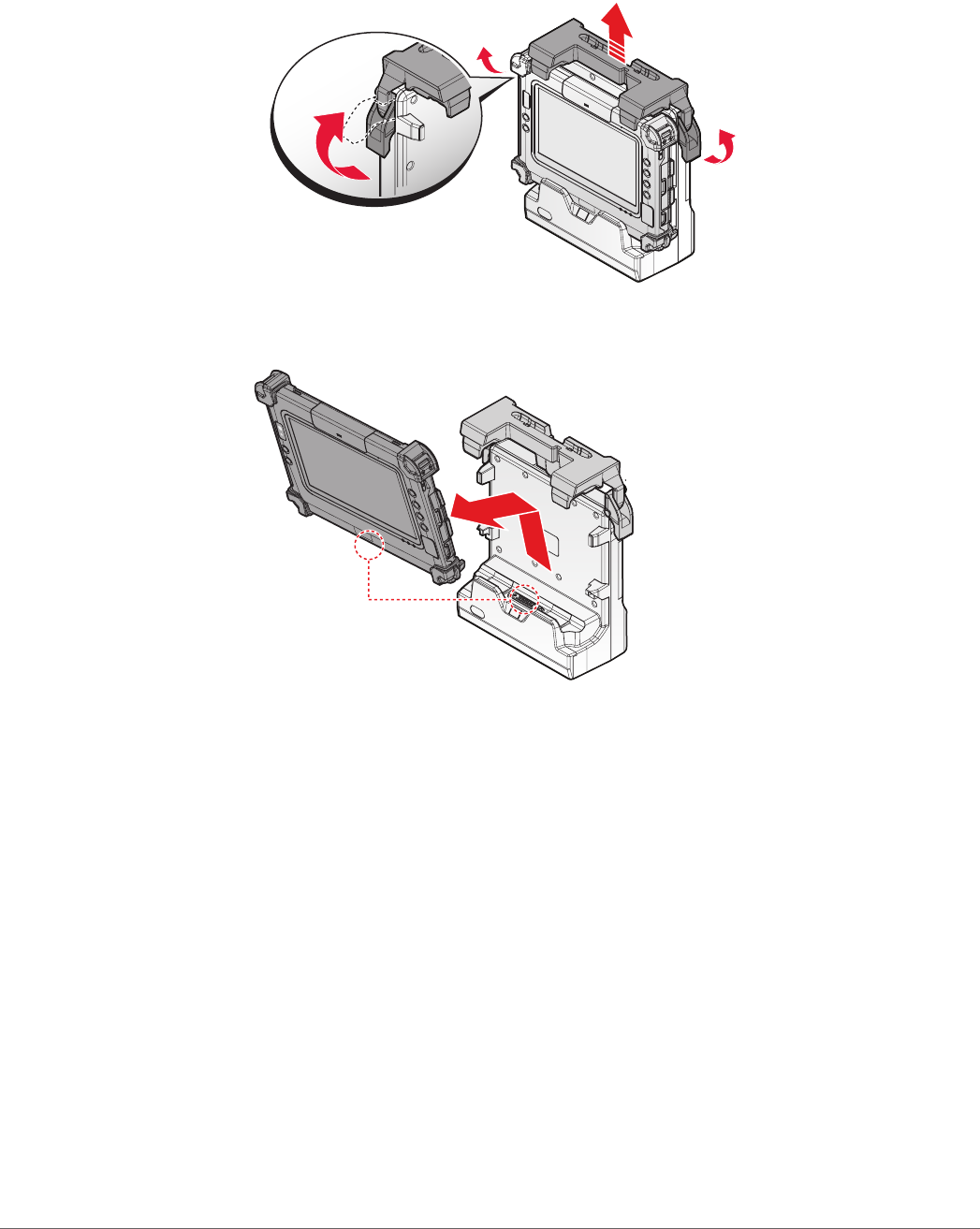
Removing from the Vehicle Dock
1. Power off the PM-311B. See “Powering Off the Device” on page 20.
2. Disconnect the cabling from the vehicle dock.
3. Flip the levers upward on the both sides.
Figure 29. Releasing the Levers
4. Remove the PM-311B from the vehicle dock with an angle.
Figure 30. Removing the PM-311B
29
Getting Started
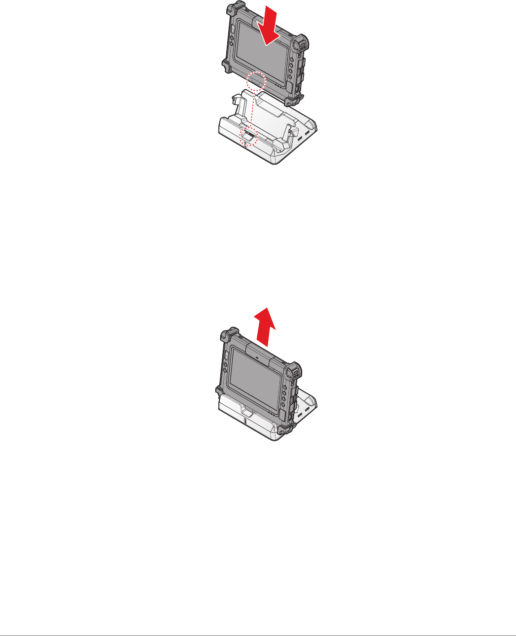
Installing on the Desktop Dock
1. Power off the PM-311B. See “Powering Off the Device” on page 20.
2. Align the docking connector on the PM-311B with the connector on the desktop dock and
push downward.
3. Push the PM-311B downward.
Figure 31. Installing the PM-311B
4. Connecting the cabling to the desktop dock.
Removing from the Desktop Dock
1. Power off the PM-311B. See “Powering Off the Device” on page 20.
2. Disconnect the cabling from the desktop dock.
3. Remove the PM-311B from the desktop dock.
Figure 32. Removing the PM-311B
30
Getting Started
Using the Stylus
Following the information below when using a stylus:
Use only the included stylus to touch the screen. Do not place any objects on its surface and
do not press down strongly with sharp-pointed or hard objects that may leave marks (e.g.,
nails, pencils and ball point pens).
Use the stylus only for touching the screen. Using it for any other purpose may damage the
stylus and result in scratches on the screen.
The pointer cannot follow the stylus movement if you move the stylus too quickly.
To make a selection, tap the screen once with the stylus. To double-click, tap twice without
pausing. To do a long click, tap the screen and hold it for a few seconds.
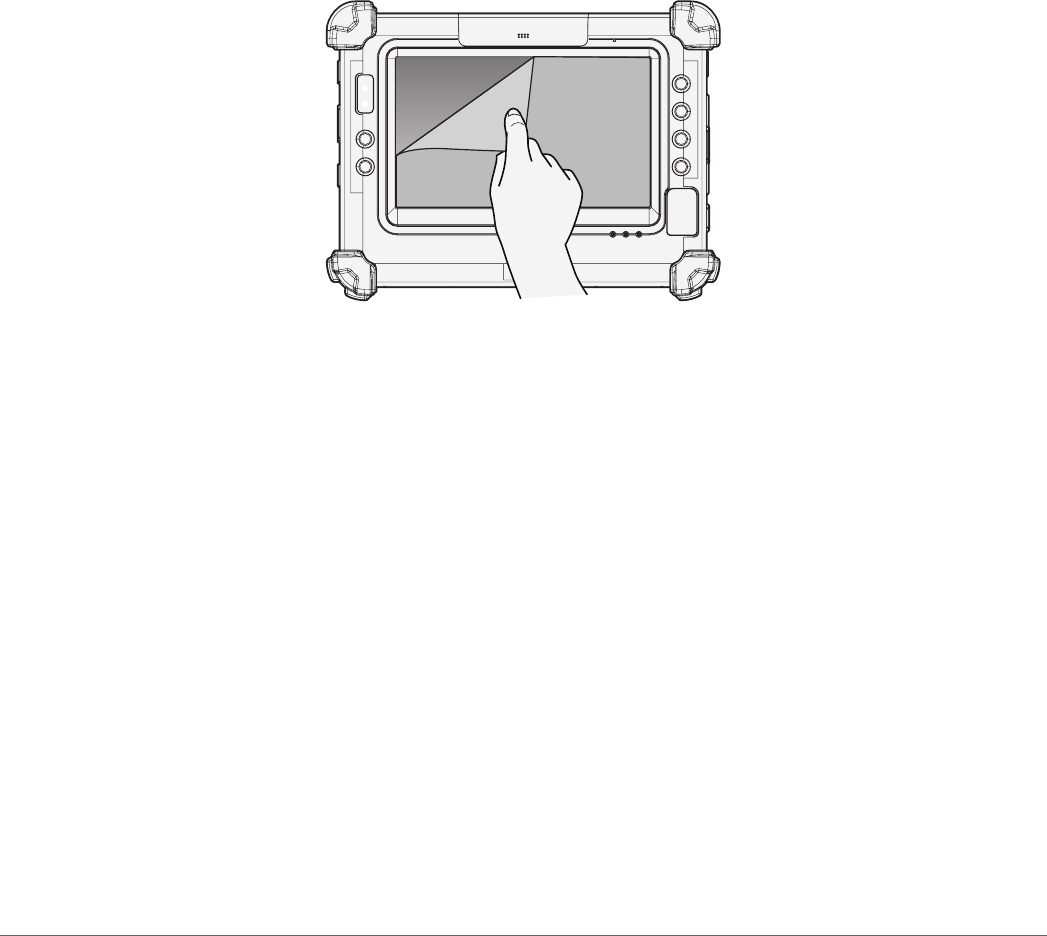
Removing the Protective Film from the Display
The front display of the PM-311B is protected during transport by a transparent lm. This lm
should remain on the front display during assembly to avoid damage to the front display surface.
Only remove the lm once all of the assembly work has been completed.
Figure 33. Removing the Protective Film
31
Operation
Chapter 3. Operation
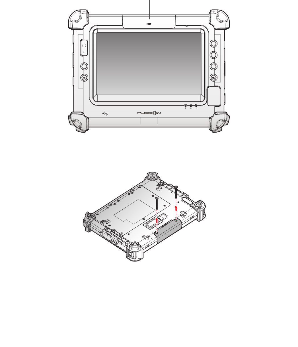
Removing the Snap-on Module Connector Cover
The snap-on module connector is located on the top side of the device. For further information see
“Overview” on page 10
1. Locate the snap-on module connector cover.
P4
P2
P3
P1
Snap-on Module Connector Cover
Figure 34. Front View: Locating the Snap-on Module Connector Cover
2. Place the device display side down on a clean work surface.
3. Remove the screws securing the cover.
Figure 35. Removing the Screws
32
Operation
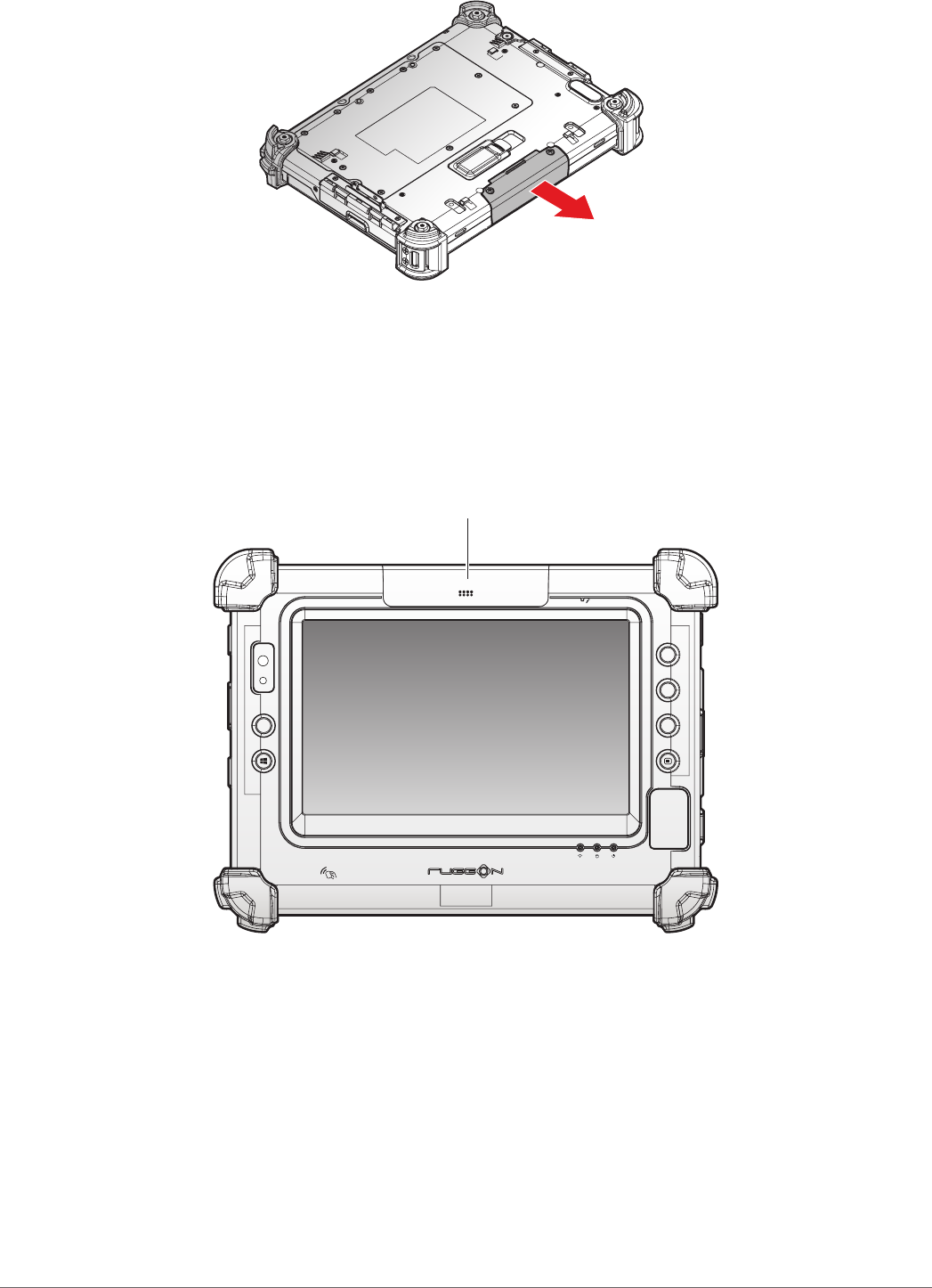
4. Remove the cover.
Figure 36. Removing the Snap-on Module Connector Cover
Replacing the Snap-on Module Connector Cover
The snap-on module connector is located on the top side of the device. For further information see
“Overview” on page 10.
1. Locate the snap-on module connector cover.
P4
P2
P3
P1
Snap-on Module Connector Cover
Figure 37. Front View: Locating the Snap-on Module Connector Cover