Contents
Users Manual-2
33
Operation
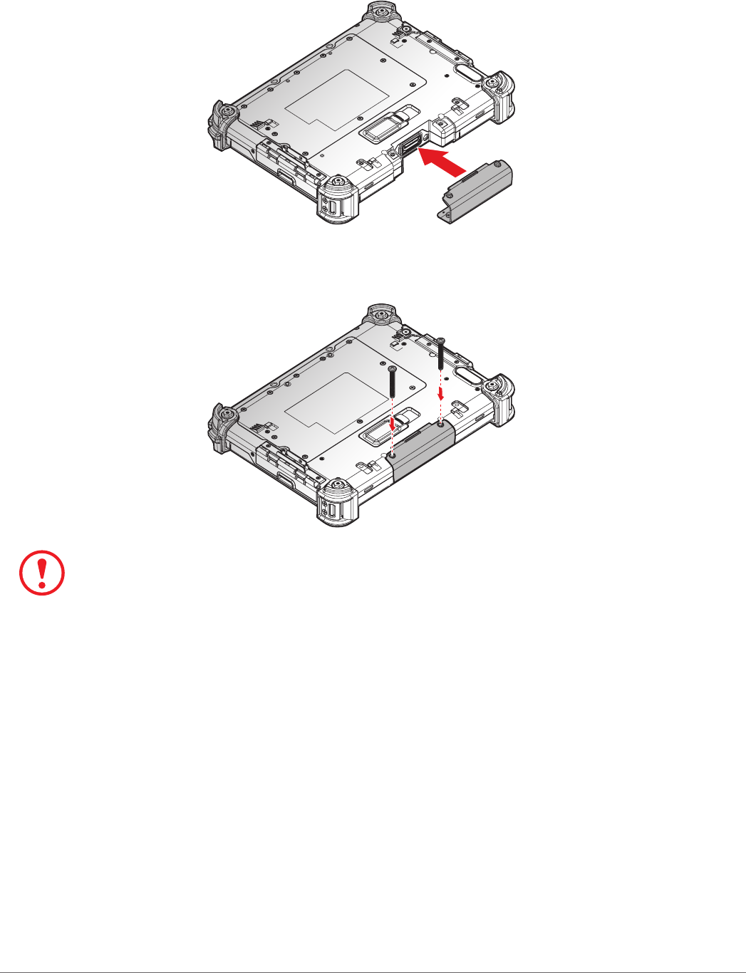
2. Align the holes on the bottom of the cover with the pins on the top of the housing and insert.
3. Place the device display side down on a clean work surface.
Figure 38. Installing the Snap-on Module Connector Cover
4. Secure the cover and the PM-311B with screws.
Figure 39. Securing the Screws
Snap-on module connector cover is not be closed well may damage the PM-311B.
34
Operation
Opening the I/O Compartment Cover
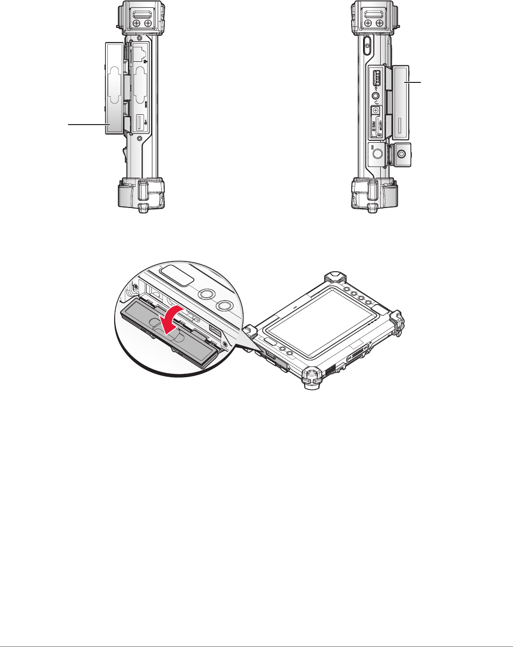
1. Place the device display side down on a clean work surface.
2. Locate the I/O compartment cover.
Right viewLeft view
Left I/O
Compartment
Cover
Right I/O
Compartment
Cover
Figure 40. Side View: Locating the I/O Compartment Cover
3. Pull out the I/O compartment cover.
Figure 41. Opening the I/O Compartment Cover
35
Operation
Closing the I/O Compartment Cover
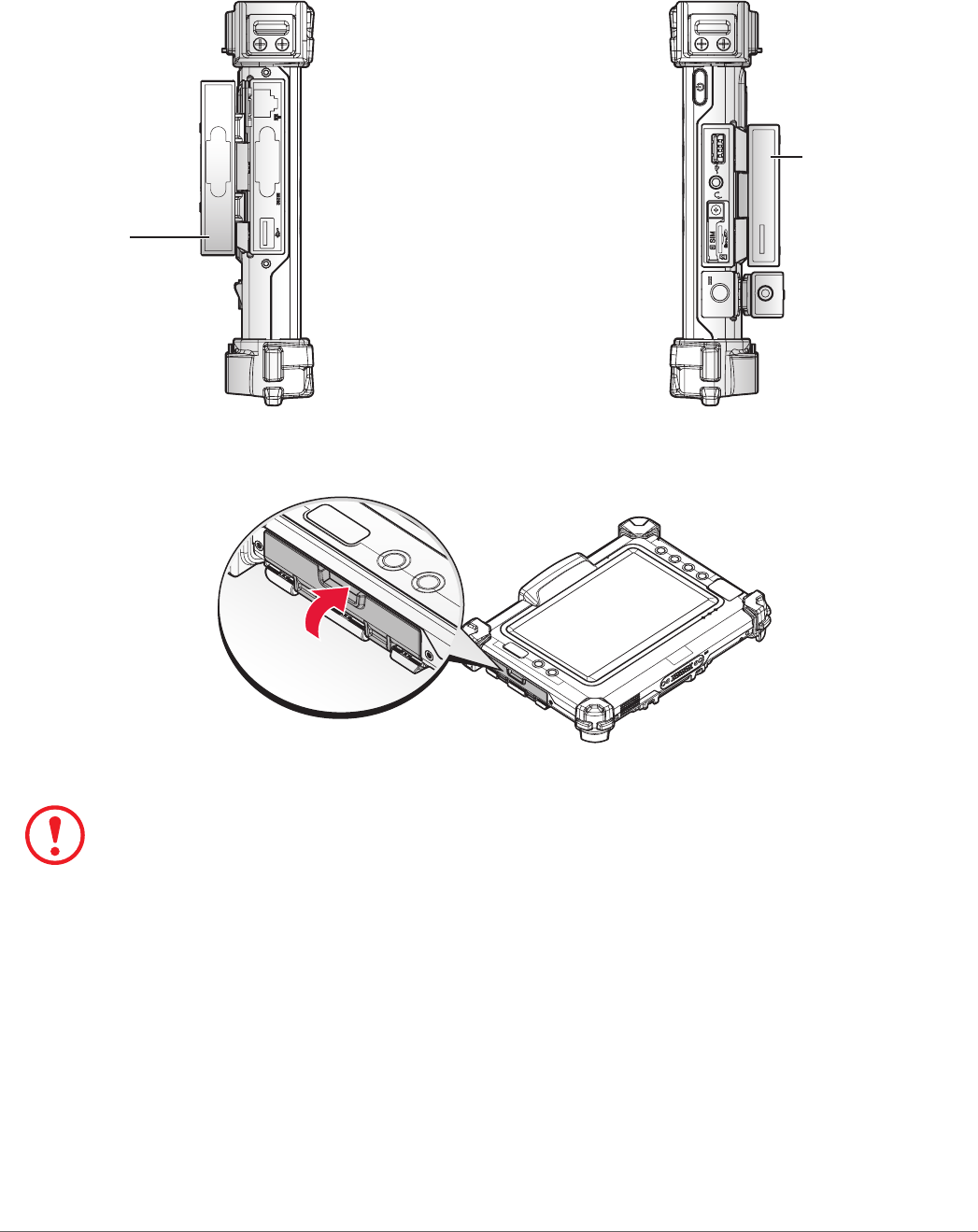
1. Place the device display side down on a clean work surface.
2. Locate the I/O compartment cover.
Right viewLeft view
Left I/O
Compartment
Cover
Right I/O
Compartment
Cover
Figure 42. Side View: Locating the I/O Compartment Cover
3. Flip the I/O compartment cover and install.
Figure 43. Closing the I/O Compartment Cover
The I/O compartment cover must be inserted correctly to prevent internal damage to the device.
36
Operation
Connecting to External Cabling
To prevent damage to the device, connect all cabling and accessories before
powering up the device.
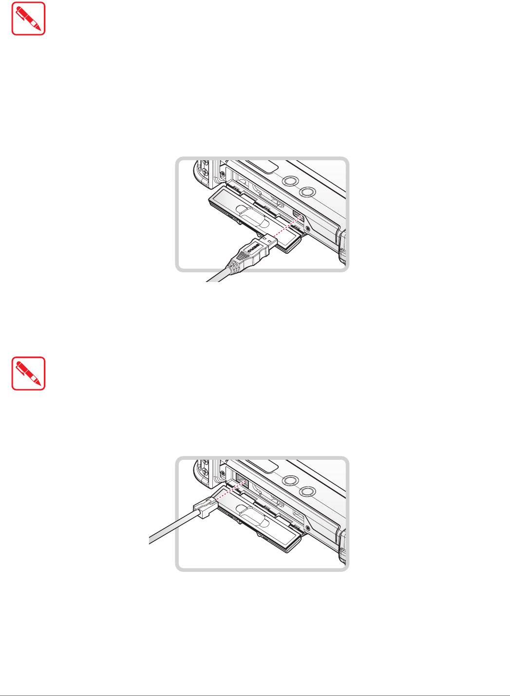
Connect USB Cabling
The PM-311B have two USB ports for connecting USB devices, such as a digital camera, scanner,
printer, modem, and mouse. The USB port support USB 2.0 or USB 3.0 devices.
1. Open the left or right I/O compartment cover. See “Opening the I/O Compartment Cover” on
page 34.
2. Connect to USB device via USB cable.
Figure 44. Connect USB Cabling
Connect Ethernet Cabling
The PM-311B provide have a Ethernet port for connecting Ethernet.
Use a shielded cable is required to maintain emissions and susceptibility compliance.
1. Open the left I/O compartment cover. See “Opening the I/O Compartment Cover” on page
34.
2. Connect LAN cable to Ethernet port on the PM-311B.
Figure 45. Connect Ethernet Cabling
37
Operation
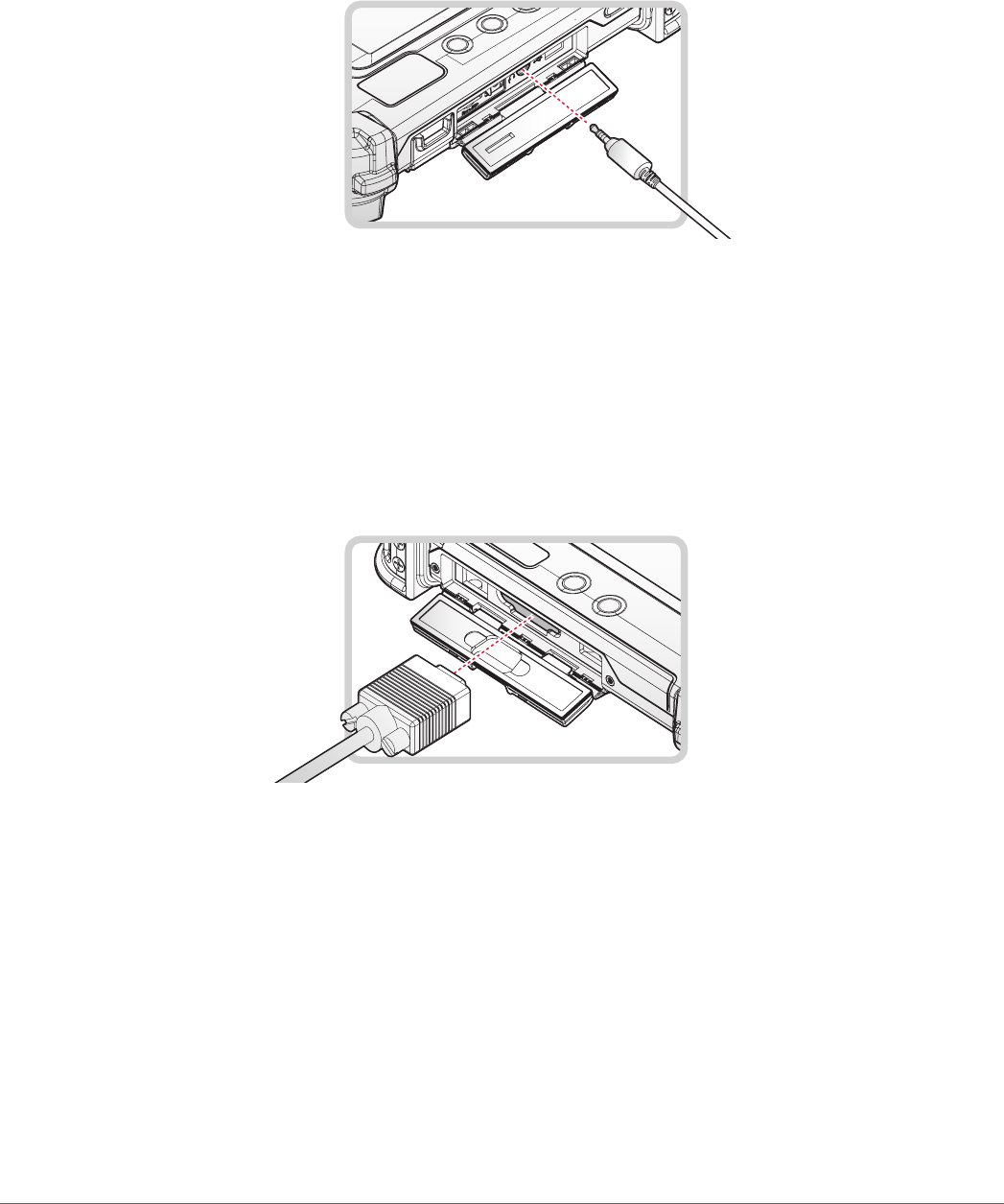
Connect Audio Cabling
For higher audio quality, you can send sound through external audio devices such as speakers,
headphones, or earphone using audio connector.
1. Open the right I/O compartment cover. See “Opening the I/O Compartment Cover” on page
34.
2. Connect the audio cable.
Figure 46. Connect Audio Cabling
Connect RS-232 Cabling
Connect to RS-232 devices with an RS-232 cable.
1. Open the left I/O compartment cover. See “Opening the I/O Compartment Cover” on page
34.
2. Align the RS-232 cable with the port in the device and connect it.
3. Turn the locking screws on the cable to secure it to the device.
Figure 47. Connect RS-232 Cabling
38
Operation
Handstrap, Carrying Handle and Shoulder Strap
The PM-311B is equipped with a handstrap, a carrying handle and a shoulder strap for
convenience and choice. Select the accessory that is right for your needs.
The handstrap can be installed with either the shoulder strap or the carrying handle. However, the
handle and shoulder strap can not be installed together due to space constraints.
For more information, see “Connecting the Handstrap” on page 38, “Connecting the Carrying
Handle” on page 39 and “Connecting the Shoulder Strap” on page 41.
Connecting the Handstrap
The handstrap makes it easy to carry the device with a single hand.
When attached, the handstrap blocks access to the external battery and connector. To install the
external battery, you will need to remove the handstrap if it is previously installed.
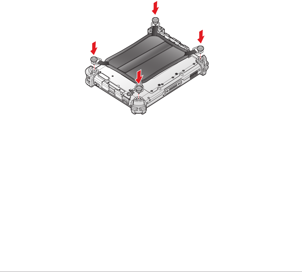
1. Position the handstrap so that the inner strap is facing the device.
2. Place the D-rings over the upper and lower positions on the device.
3. Twist the D-rings (clockwise) to secure the handstrap.
Figure 48. Securing the Handstrap
39
Operation
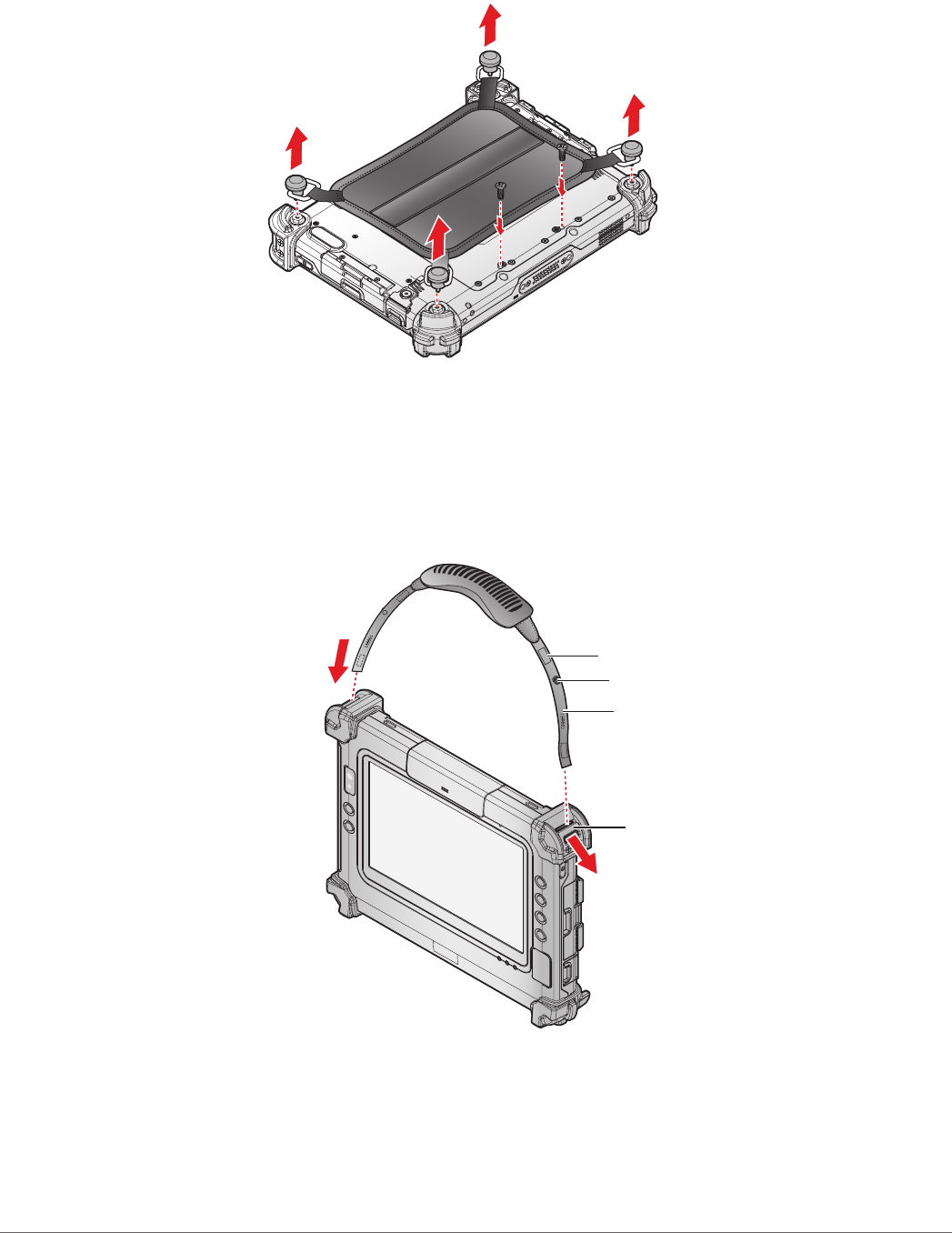
Removing the Handstrap
1. Unscrew the D-rings securing the handstrap to the device.
2. Remove the handstrap from the PM-311B.
Figure 49. Removing the Handstrap
Connecting the Carrying Handle
1. The handle must face the correct way. The securing post and velcro should be facing
outward.
2. Thread one end of the strap through the metal loop on the bumper.
Strap
Metal Loop
Post
Velcro
Figure 50. Inserting the Carrying Handle Through the Loop
40
Operation
3. Pull the strap end through the loop and insert the post through the slit on the strap.
4. Secure the strap by attaching the two velcro ends together.
Figure 51. Securing the Strap
5. Repeat fro the remaining strap end.
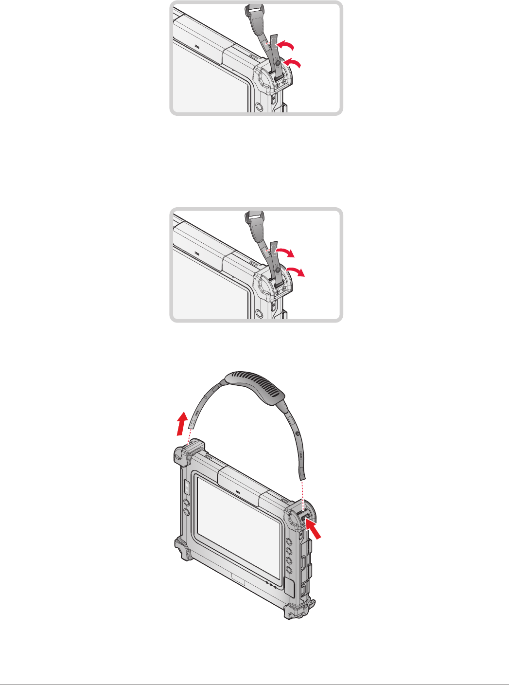
Removing the Carrying Handle
1. Remove the strap from the velcro and securing post.
Figure 52. Removing the Strap
2. Pull the strap through the metal loop on the bumper.
Figure 53. Removing the Carrying Handle
3. Repeat fro the remaining strap end.
4. Remove the carrying handle.
41
Operation
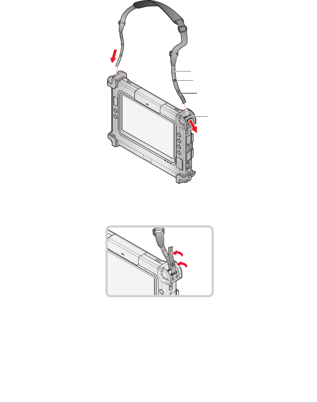
Connecting the Shoulder Strap
1. The shoulder strap must face the correct way. The securing post and velcro should be facing
outward.
2. Thread one end of the strap through the metal loop on the bumper.
Velcro
Metal Loop
Post
Velcro
Figure 54. Inserting the Shoulder Strap Through the Loop
3. Pull the strap end through the loop and insert the post through the slit on the strap.
4. Secure the strap by attaching the two velcro ends together.
Figure 55. Securing the Strap
5. Repeat for the remaining strap end.
42
Operation
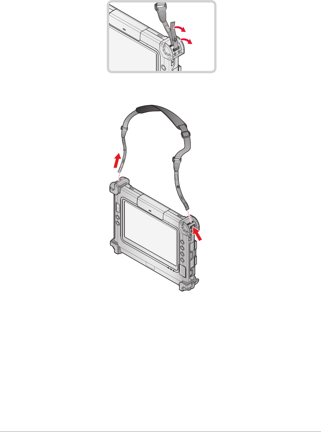
Removing the Shoulder Strap
1. Remove the strap from the velcro and securing post.
Figure 56. Removing the Strap
2. Pull the strap through the metal loop on the bumper.
Figure 57. Removing the Shoulder Strap
3. Repeat for the remaining strap end.
4. Remove the shoulder strap.
43
Operation
Installing the External Battery
The external battery is an optional component. Only use components specically designed for this
device. Contact your local representative for ordering information.
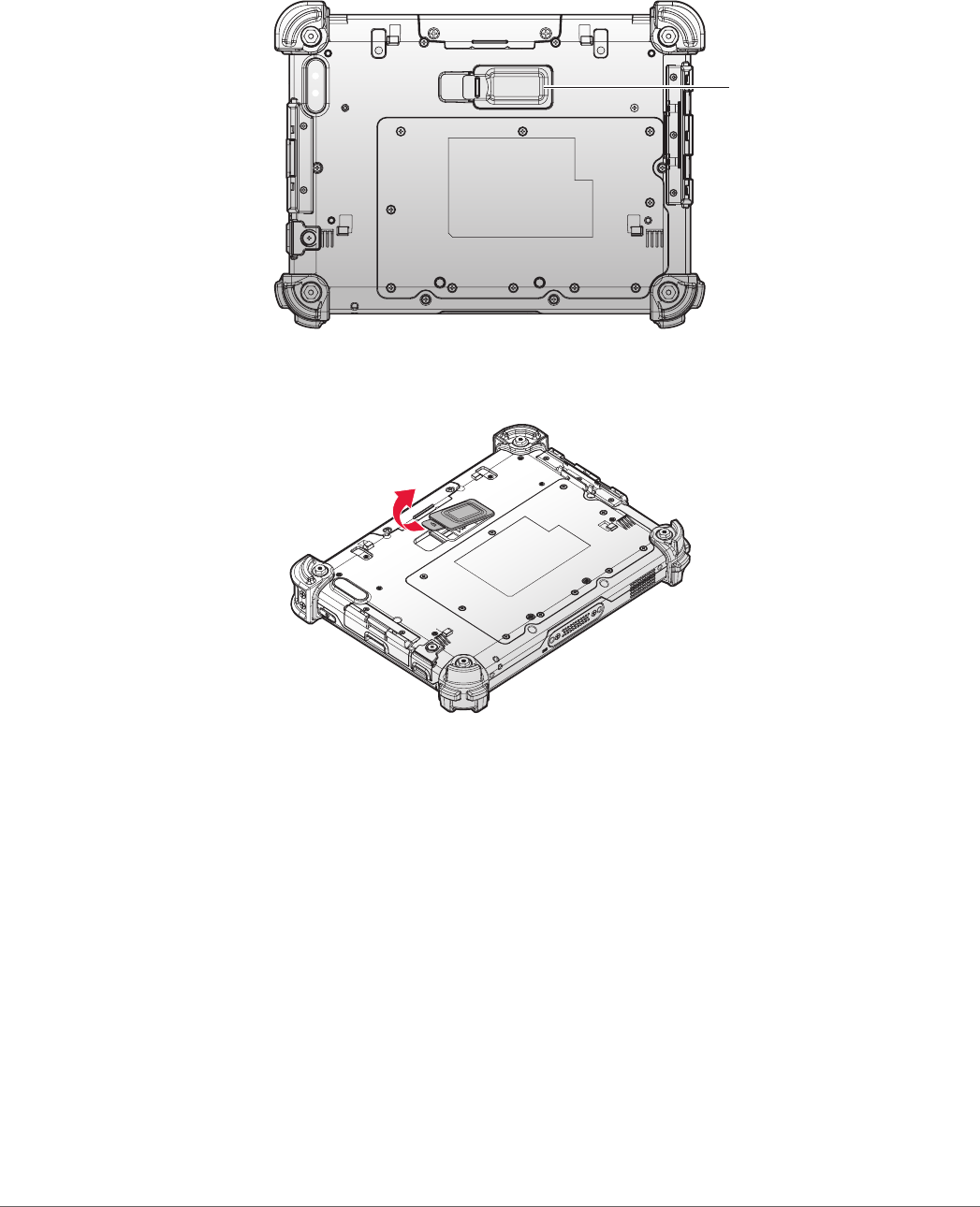
1. Place the device display side down on a clean work surface.
2. Locate the external battery connector cover.
External Battery
Connector Cover
Figure 58. Rear View: Locating the External Battery Connector Cover
3. Flip the connector cover up to remove it from the compartment.
Figure 59. Removing the External Battery Connector Cover
44
Operation
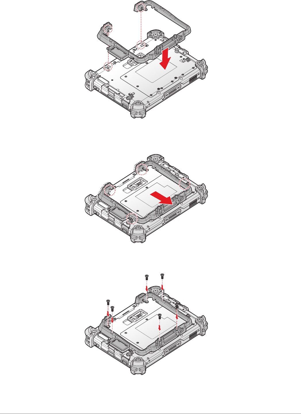
4. Align the tabs on the external battery bracket with the slots on the rear side of the PM-311B .
Figure 60. Aligning the External Battery Bracket
5. Push the external battery bracket toward to lock.
Figure 61. Installing the External Battery Bracket
6. Securing the external battery bracket and the PM-311B with screws.
Figure 62. Securing the Screws
45
Operation
7. Install the connector cover in the cover placeholder.
Figure 63. Placing the External Battery Connector Cover in the Cover Placeholder
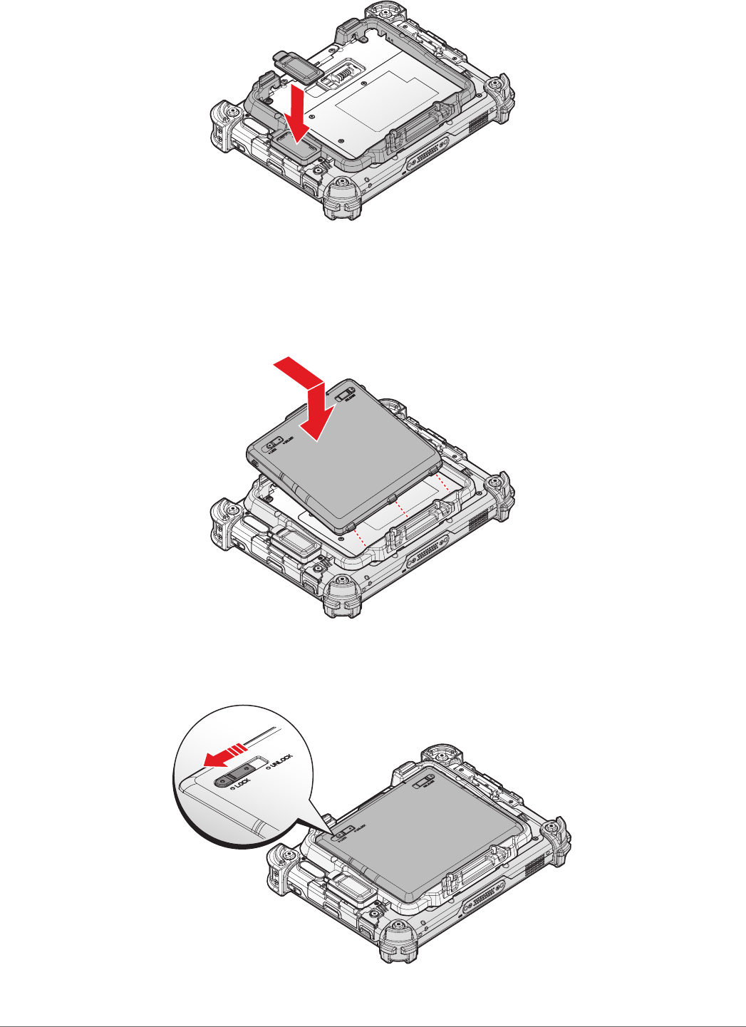
8. Align the tabs on the external battery with the slots on the external battery bracket.
9. Angle the battery in place and set the tabs in the bracket slots.
10. Lower the raised end of the external battery and press in place until an audible click is heard.
Figure 64. Installing the External Battery
11. Press the locking switch on the top-left side to lock the external battery.
Figure 65. Locking the External Battery