RuggON VM-521 Panel PC User Manual VM 521 UM DFA 09022x
RuggON Corporation Panel PC VM 521 UM DFA 09022x
RuggON >
Contents
- 1. User manual 1
- 2. User manual 2
User manual 2
Hardware Installation
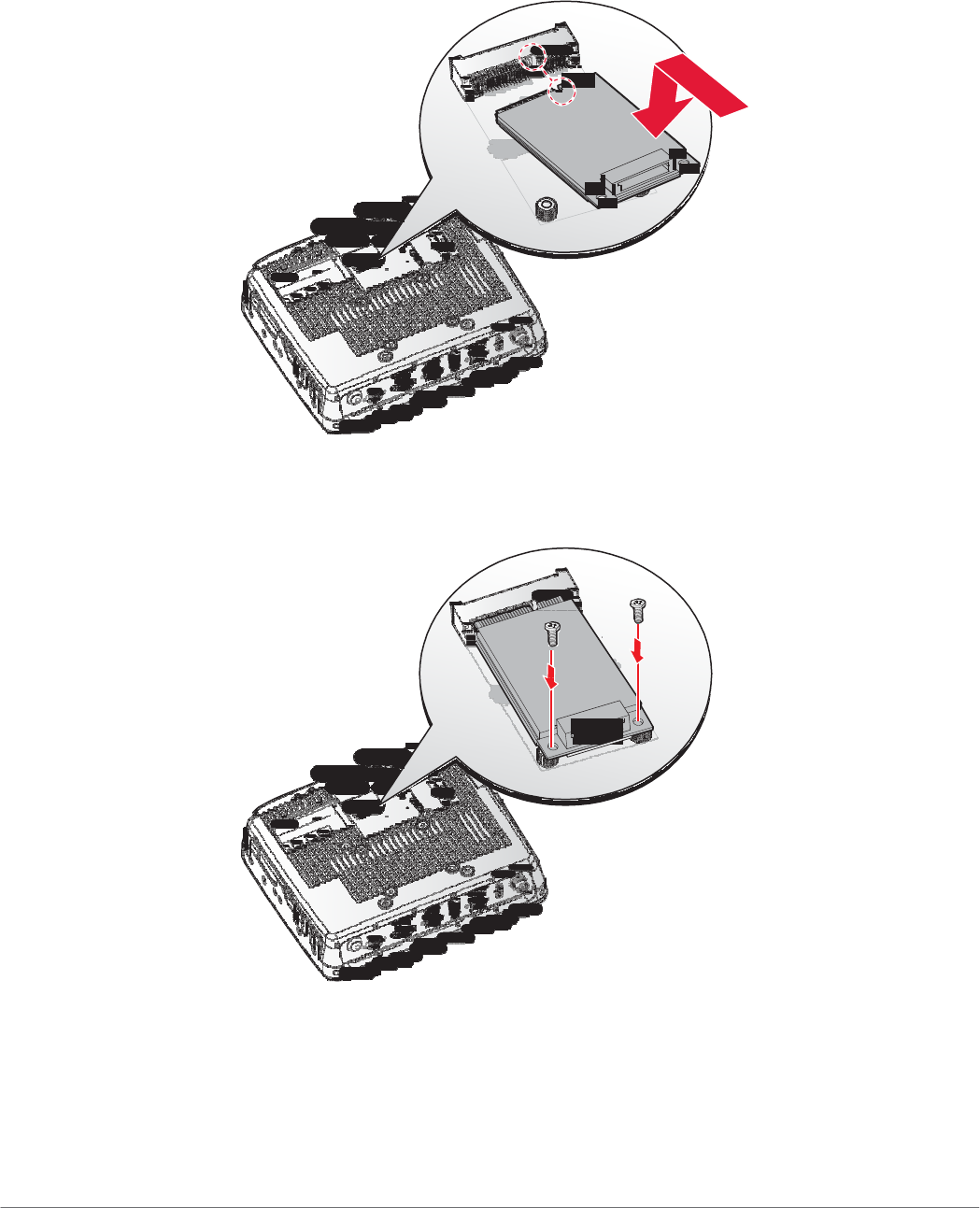
8. Align the indentation on the PCIe card with the protrusion on the slot connectors.
9. Angle the card and slide it in place. Gently push the card in to seat correctly.
10. Press the opposite end down over the screw posts. The holes on the card must line up with
the holes in the screw posts.
Figure 36. Installing a mini PCIe Card
11. Secure the mini PCIe card to the VM-521 with the provided screws.
Figure 37. Securing the Screws
12. Connect the mini PCIe cabling to the mini PCIe card.
13. Install the SSD module. See “SSD Module” on page 32.
14. Replace the service cover. See “Replacing the Service Cover” on page 28.
36
Hardware Installation
Removing a mini PCIe Card
1. Power down the device and disconnect from all the power source.
2. Unmount the device from the mounting apparatus.
3. Place the device display side down on a clean work surface.
4. Open the service cover. See “Removing the Service Cover” on page 27.
5. Remove the SSD module. See “Removing an SSD Module” on page 34.
6. Disconnect mini PCIe cabling from the mini PCIe card.
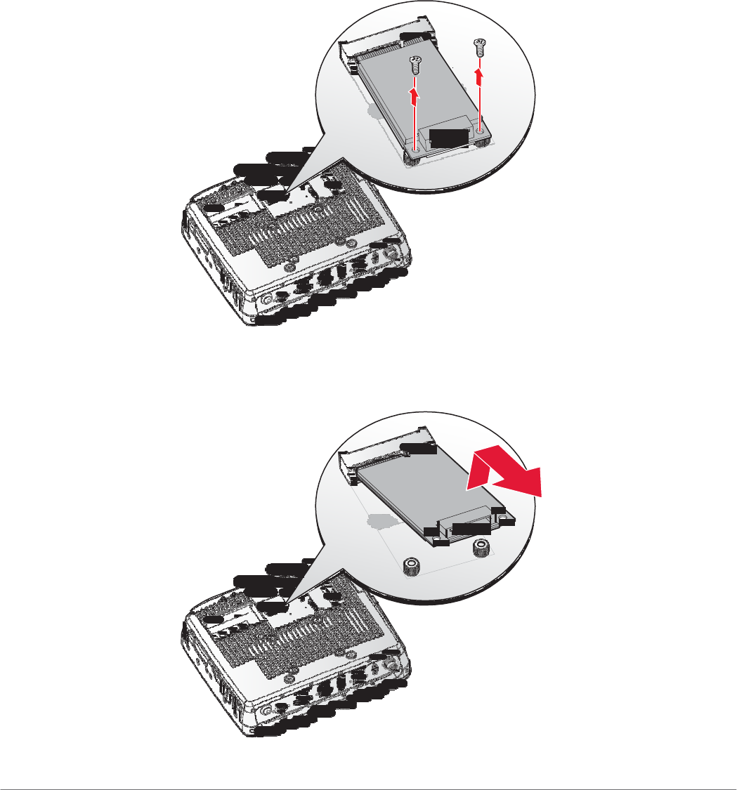
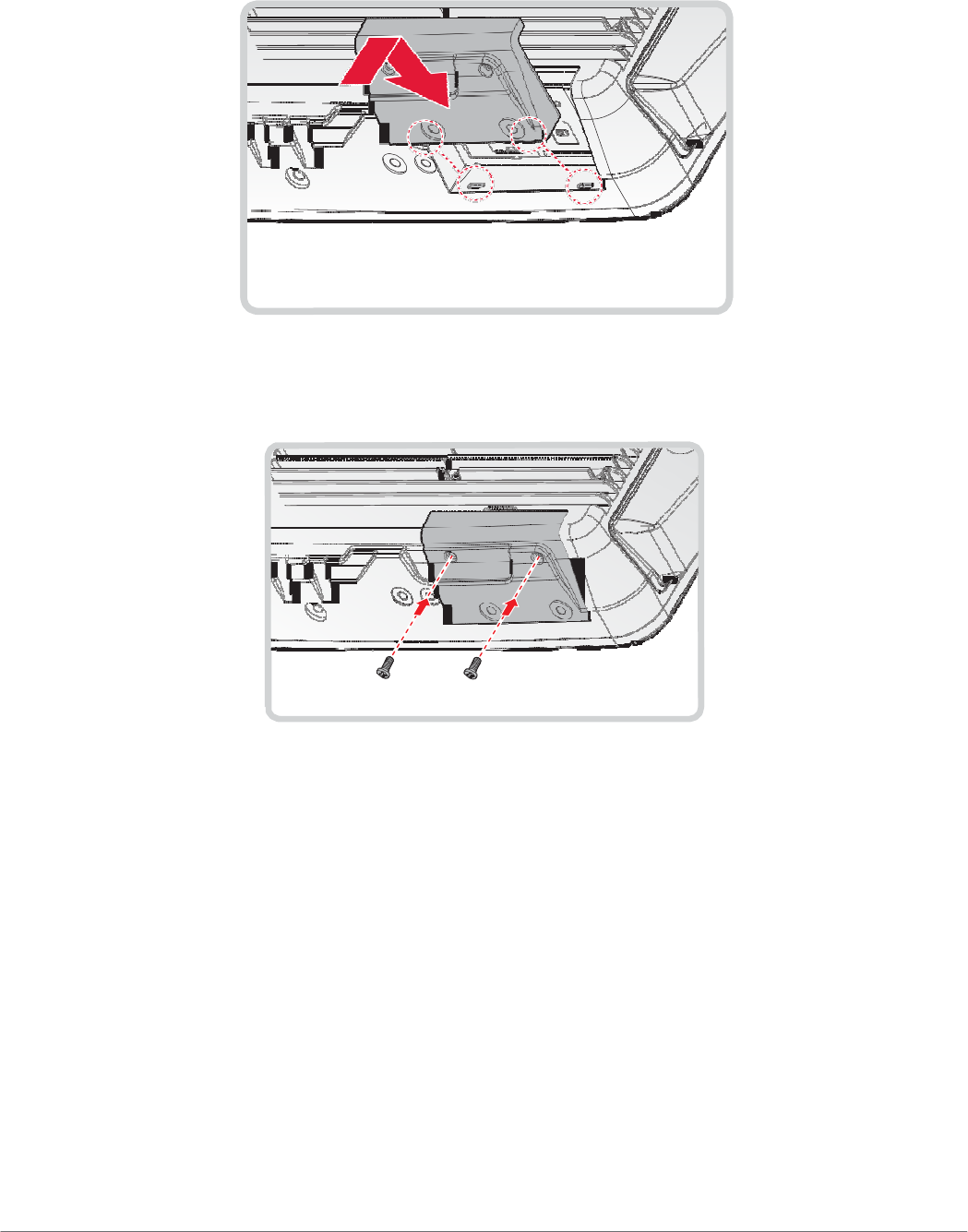
7. Remove the screws securing the mini PCIe card to the VM-521.
Figure 38. Removing the Screws
8. Disconnect the mini PCIe card from the VM-521.
Figure 39. Removing a mini PCIe Card
37

Hardware Installation
9. Install the SSD module. See “SSD Module” on page 32.
10. Replace the service cover. See “Replacing the Service Cover” on page 28.
38

Hardware Installation
39

Hardware Installation
40
Hardware Installation
Removing the Communications Cover
The communications bay is located on the left rear side of the device. For further information see
“Device Overview” on page 11.
1. Power down the device and disconnect from all the power source.
2. Unmount the device from the mounting apparatus.
3. Place the device display side down on a clean work surface.
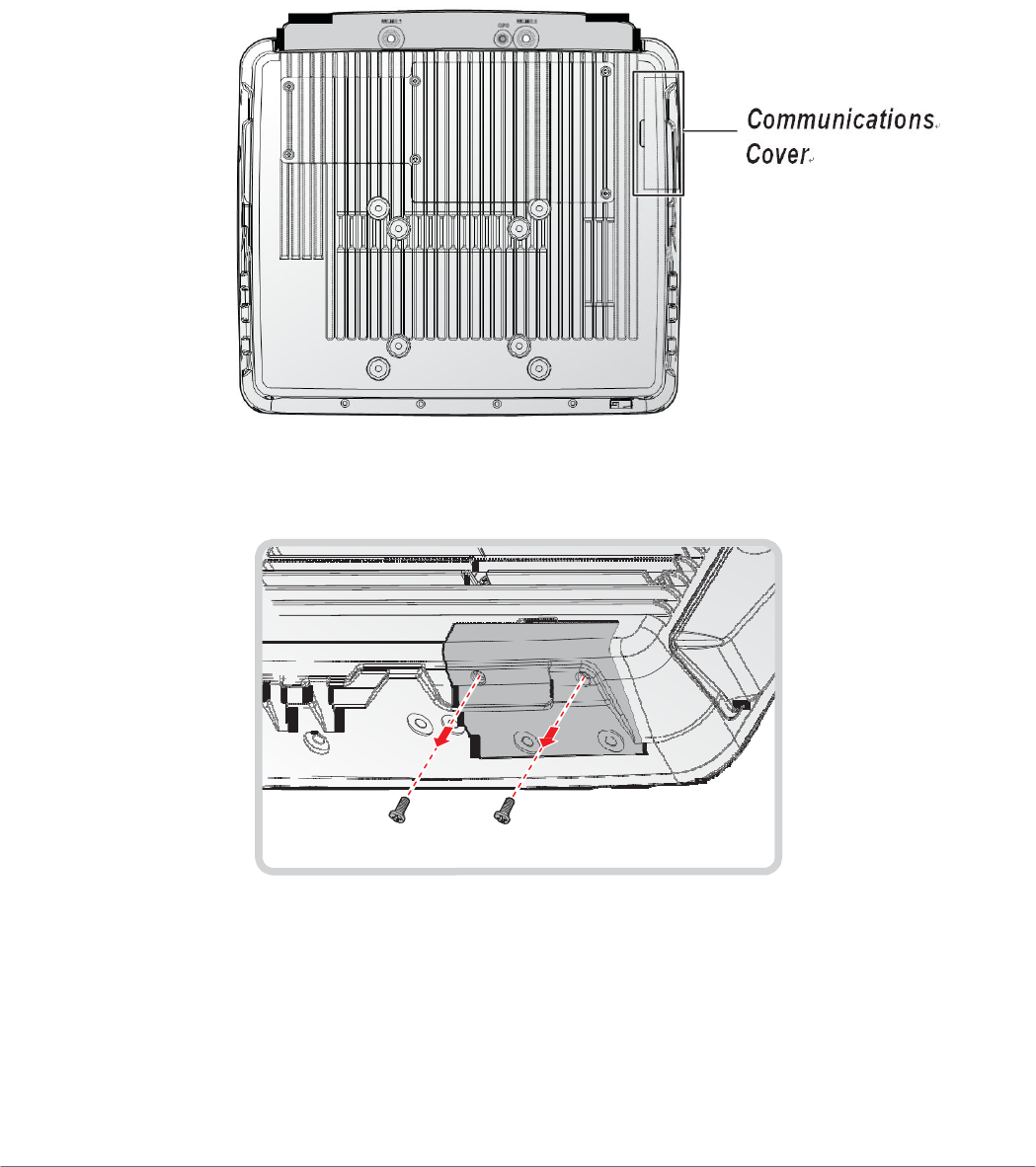
4. Locate the communications cover.
Figure 45. Rear View: Locating the Communications Cover
5. Remove the screws securing the cover.
Figure 46. Removing the Screws
41
Hardware Installation
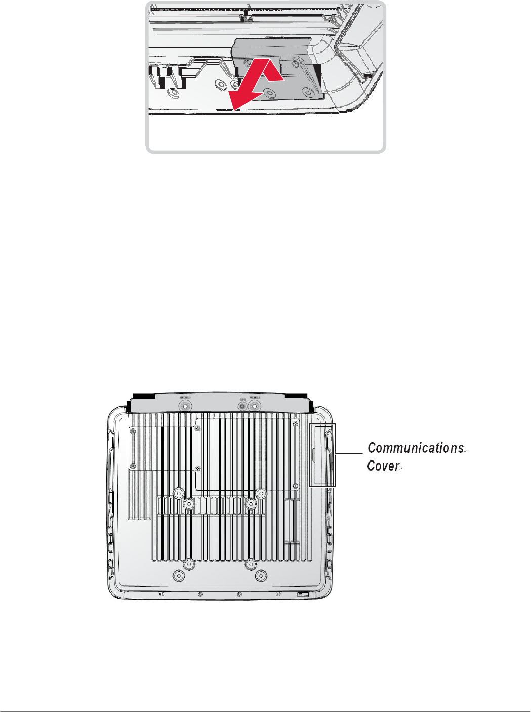
6. Open the cover as shown in the following image.
Figure 47. Removing the Communications Cover
Once the communications cover is removed, you can install or remove the following items:
„
SD card
Replacing the Communications Cover
The communications bay is located on the left rear side of the device. For further information see
“Device Overview” on page 11.
1. Power down the device and disconnect from all the power source.
2. Unmount the device from the mounting apparatus.
3. Place the device display side down on a clean work surface.
4. Locate the communications cover.
Figure 48. Rear View: Locating the Communications Cover
5. Align the tabs on the bottom of the cover with the indentations in the bay.
6. Angle the bottom of the device and insert the tabs in the protrusions. See the following
image.
42
Hardware Installation
7. Slide the remaining part of the cover in place.
Gently press it in place to seat it properly. If installed correctly, there should be no gaps
between the cover and the chassis.
Figure 49. Inserting the Communications Cover
8. Secure the communications cover and the VM-521 with screws.
Figure 50. Securing the Screws
9. Return the device to the mounting apparatus and install.
43

Hardware Installation
44

Hardware Installation
45
Hardware Installation
Installing an SD Card
The device supports different types of memory cards for easier data storage. The supported types
for SD cards are as follows:
„
SD card
„
SDHC card
„
Mini-SD card (with adapter)
1. Power down the device and disconnect from all power sources.
2. Unmount the device from the mounting apparatus.
3. Place the device display side down on a clean work surface.
4. Remove the communications cover. See “Removing the Communications Cover” on page
41.
5. Locate the SD slot in the communications bay.
6. Take the SD card from its packaging.
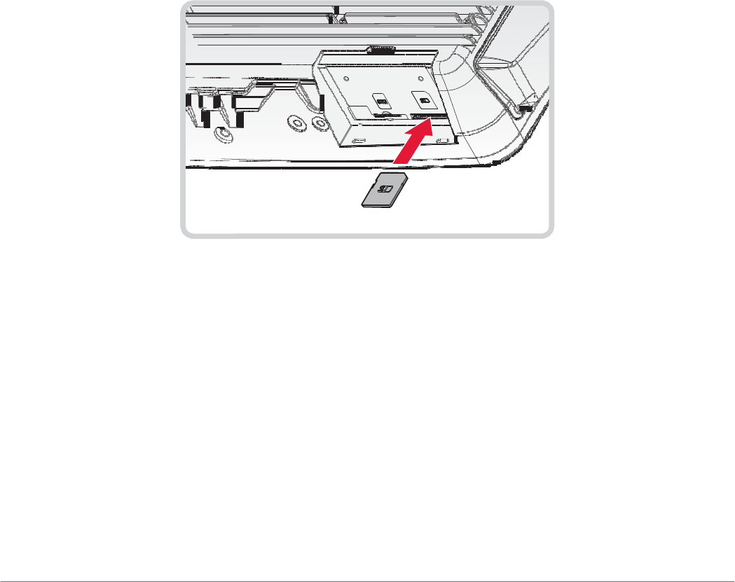
7. The SD card has a corner missing. Align the SD card with the slot making sure that the
corners match.
8. Insert the SD card and press it in until an audible click sounds.
Figure 53. Installing an SD Card
9. Replace the communications cover. See “Replacing the Communications Cover” on page
42.
46
Hardware Installation
Removing the SD Card
1. Power down the device and disconnect from all the power source.
2. Unmount the device from the mounting apparatus.
3. Place the device display side down on a clean work surface.
4. Locate the communications cover and remove it. See “Removing the Communications
Cover” on page 41.
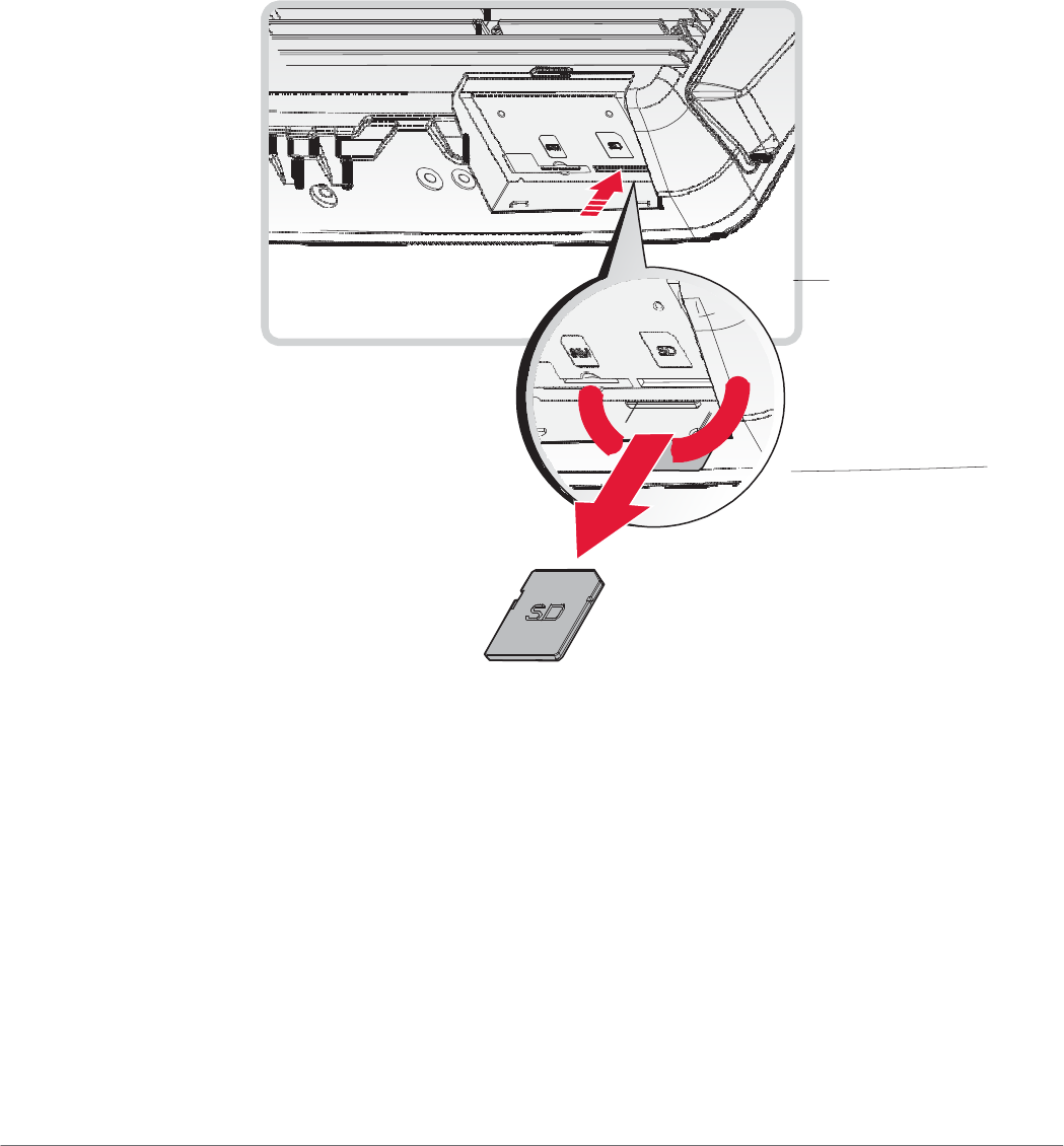
5. Press the SD card in and release it. The card springs out.
6. Grasp the SD card and remove it from the slot.
Figure 54. Removing an SD Card
7. Replace the communications cover. See “Replacing the Communications Cover” on page
42.
47
Hardware Installation
Installing Antennas
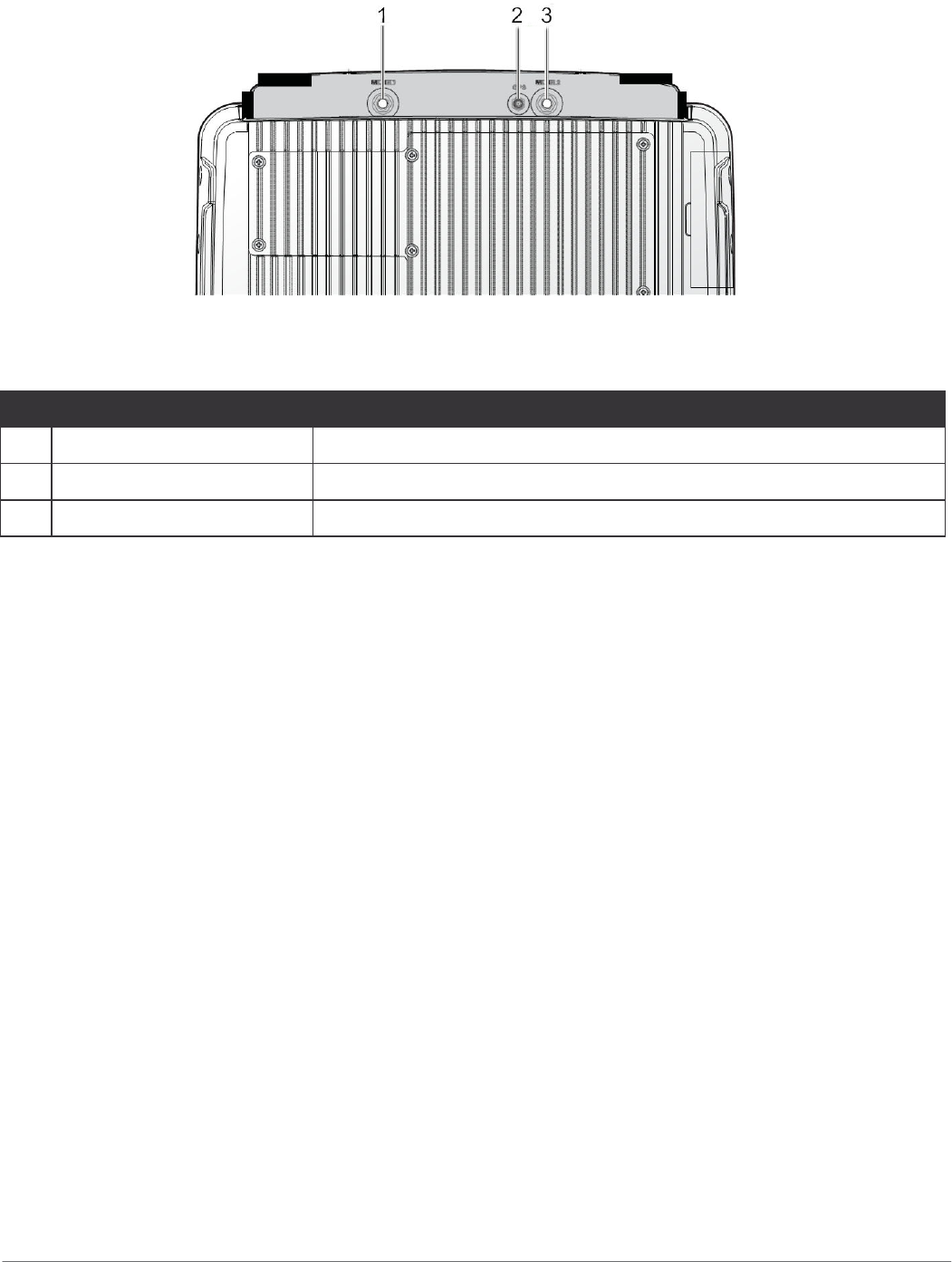
Figure 55. Antenna Instllation
Table 7. Antenna
No Item Description
No
Item
Descri
ption
1 WLAN1 Connect WLAN1 antenna.
2 GPS Connect GPS antenna.
3 WLAN2 Connect WLAN2 antenna.
Selecting an Antenna Site/Location on a Metal Body Vehicle
1. External installation – Check the requirements of the antenna supplier and install the vehicle
antenna external to a metal body vehicle in accordance with those requirements.
2. Roof top – For optimum performance and compliance with RF Energy Safety standards,
mount the antenna at the center area of the roof.
3. Ensure that the installation surface is grounded by connecting grounding straps between the
surface and the vehicle chassis.
4. Ensure that the antenna cable can be easily routed to the VM-521. Route the antenna cable
as far away as possible from any vehicle electronic units and its associated wiring.
5. Check the antenna location for any electrical interference.
48

Hardware Installation
Connecting a WLAN Radio Antenna
The WLAN antenna for the VM-521 mobile workstation is an optional component available through
your representative. For WLAN connector locations see “Installing Antennas” on page 48.
An external WLAN antenna jack is located on the rear of the device. To connect an external
antenna, the connector end of the antenna must be RP SMA male to fit into the RP SMA female
jack on the device.
To install the WLAN antenna to the vehicle, refer to the installation instructions as referred by the
manufacturer of the antenna.
GPS Antenna Connection
The GPS antenna for the VM-521 mobile workstation is an optional component available through
your representative. For GPS connector locations see “Installing Antennas” on page 48.
An external GPS antenna jack is located on the rear of the device. To connect an external
antenna, the connector end of the antenna must be RP SMA male to fit into the RP SMA female
jack on the device.
To install the GPS antenna to the vehicle, refer to the installation instructions as referred by the
manufacturer of the antenna.
To prevent a short circuit from occurring, the fitting differential between the center conductor and the
ground GPS antenna should be 3.0V or lower.
49

Hardware Mounting
Chapter 4.
Hardware Mounting
Mounting Instructions
Read all instructions thoroughly before beginning the installation procedure. See the User Manual for further safety and
installation information.
To prevent the damage to the hardware or injury to personnel, always ensure that there are two
individuals to help in carrying and supporting the installation/removal process.
Assembly Site
The VM-521 is ruggedized for harsh operational conditions. For best installation practices observe
the following installation guidelines:
„
Do not expose the Industrial PC to direct heat. Make sure that there is sufficient cross
ventilation.
„
Allow at least 15 mm more depth for front installation devices to ensure sufficient air
circulation.
„
Do not mount the device on equipment that strongly vibrates. Shock absorbers and vibration
dampers may be required if installing in such environments.
Tools Required
You need the following tools for mounting or opening the device:
„
Philips recessed head screwdriver, size 1 (PH 1)
Device Enclosure
The VM-521 supports the installation of various wall and wall mounting brackets. The following
illustrations displays the screw locations for the supported installation types.
To prevent any damage or injury, make sure the mounting bracket is securely attached.
50
Hardware Mounting
The VM-521 also supports two types of VESA mounts.
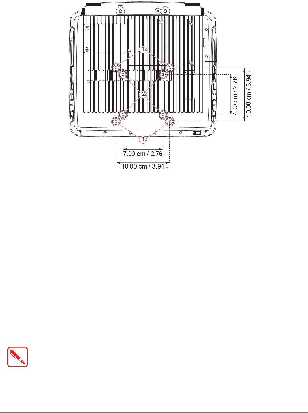
Figure 56. Rear View, dimensions in centimeters and inches
VESA 100 Mounting Option
VESA 100 mounting option, M5 thread
The VM-521 supports a standard VESA version MIS-D, 100, C (100 mm distance quadrate
order, M5 thread, deepness 7.5 mm) through the four drill holes (See 1 in “Figure 56. Rear View,
dimensions in centimeters and inches” on page 51) on the back side of the device.
VESA 75 Mounting Option
VESA 75 mounting option, M5 thread
The VM-521 supports a standard VESA version MIS-D, 75, C (75 mm distance quadrate order, M5
thread, deepness 7.5 mm) through the four drill holes (See 1 in “Figure 56. Rear View, dimensions
in centimeters and inches” on page 51) on the back side of the device.
Device Cooling
The VM-521 is designed to use a passive cooling concept. The generated heat from the device
is dissipated through the surface of the housing. The proper function of the design requires the
use of air circulation. It is not advisable to install the device in a closed environment where air
circulation is poor and heat dissipation is not possible.
Overheating may occur if the device does not have access to fresh cooling air. The
maximum permissible ambient temperature for the entire system must be taken into
consideration during installation.
51

Hardware Mounting
Power Supply
The VM-521 is equipped with a galvanically separated, integrated DC power supply, located on the
underside of the device.
Support the cable and avoid crushing, stressing and overbending it. Cables should never be
allowed to hang freely for long distances or to press against edges in an installation.
Only use original power supply cables from RuggON.
RuggON power cables meet the specific requirements to power the device.
If other power supply cables are used:
- The user/operator is solely responsible for the resulting damage. All warranties by RuggON are voided.
Vehicle Applications
The information in this section is intended to provide information for vehicle applicaitons.
Electrical Installation
Take the following considerations during the installation:
„
Some forklifts have a chassis that is connected to DC+. By definition, the VM-521 chassis
is also connected to DC+. However, any peripheral devices suppling DC- through an
interconnector (such as a DC- serial port), a short circuit may occur. Malfunctions will result
from this type of setup.
„
Connect the VM-521’s as close to the battery as possible. Malfunctions may occur if the the
VM-521 is conected to large electrical loads, such as converters for the forklift motor may
result in random restarts.
Locating the VM-521 in a Vehicle
If the device is installed in a vehicle, the driver’s field of view must always be kept free.
The VM-521 system may not project beyond the vehicle area.
Assembly Overview
Before installing the VM-521 to the vehicle:
„
Prepare the forklift, such as: ignition connection, and correct voltage preparation.
The following installation sequence is recommended:
1. Install the bracket to the vehicle.
2. Install the device to the bracket.
Cable Strain Relief
After installation of the VM-521 and bracket, fasten the cabling.
„
Setup the strain relief.
„
Loosely route the cabling on the strain relief rail.
Completing:
„
Secure the cabling to the strain relief rail.
„
The cabling must be fastened precisely at the cable opening location.
52
Chapter 5.
Operation
Powering the Device
Starting Up the Device
Only power up the VM-521 after connecting all of the cables.
Operation
The VM-521 is powered up by connecting it to an appropriate power supply and then using the
Power switch.
The VM-521 must be connected to an SELV circuit. Make sure there is a suitable
disconnecting device such as a power switch or circuit breaker in the power supply
circuit.
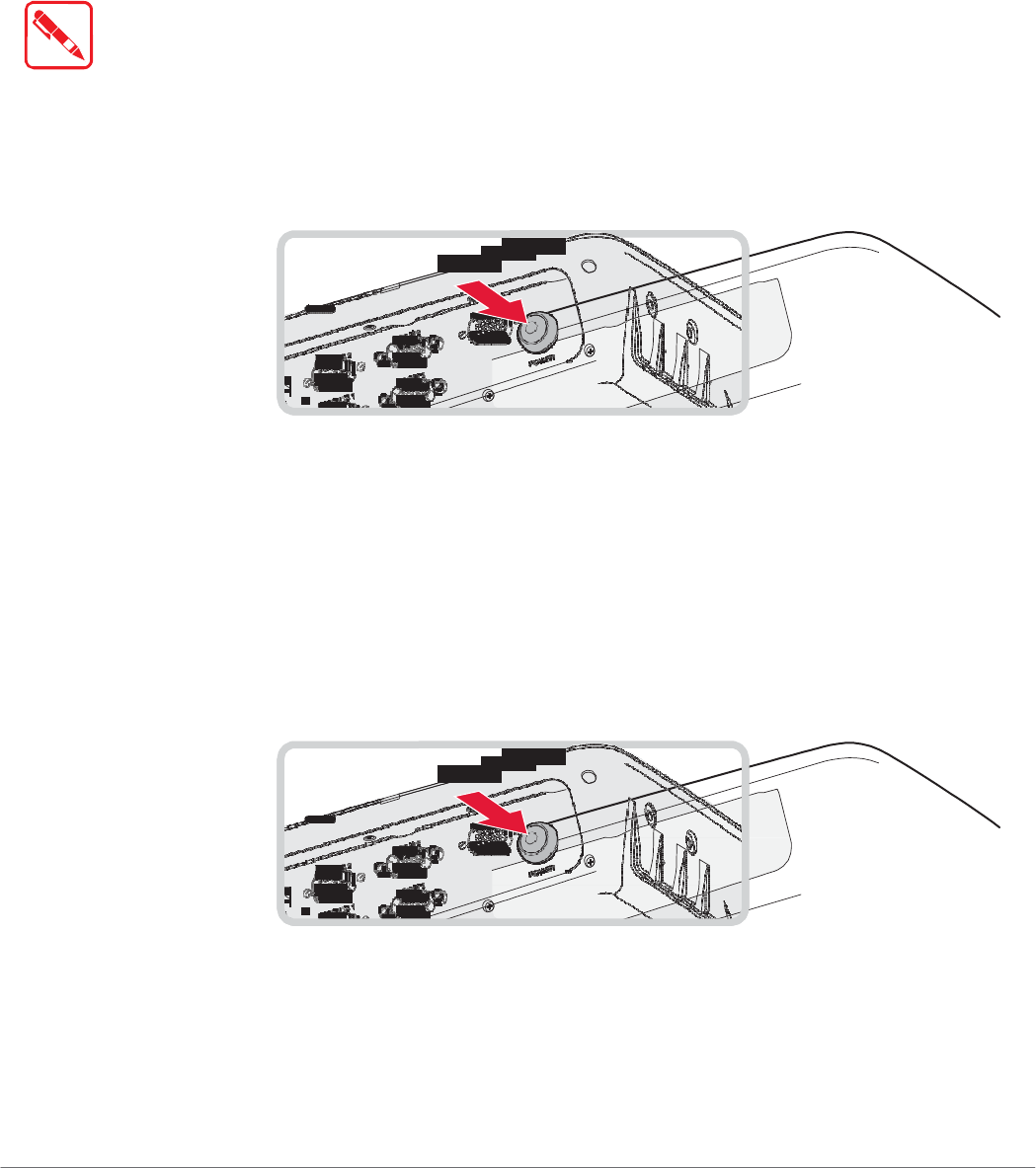
1. Locate the I/O ports at the bottom of the device.
2. Press and hold the power switch for 2 seconds.
Figure 57. Power Up the VM-521
Powering Down the Device
The VM-521 can be powered down by using the power switch or through the Windows operating
system.
To power down the device:
1. Locate the I/O ports at the bottom of the device.
2. Press and hold the power switch for 5 seconds.
Figure 58. Powering Down the VM-521
To shut down the device:
From the Home Screen, tap Start > Shut down. Once the device is completely powered down,
you can remove the power cable (if necessary).
53
Operation
Defrost/Defog Option
The touch screen is available with a defrost and defog function for users who use the device in
extreme temperature environments. The function is optional and only available upon request.
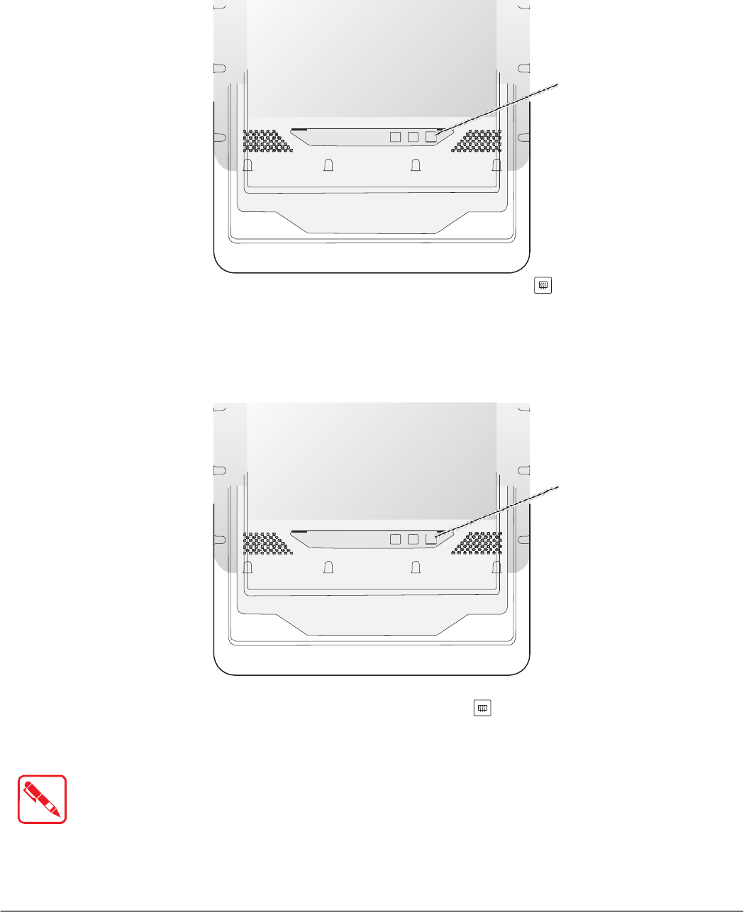
Enabling Defrost Function
Figure 59. Defrost Function
Defrost/Defog
In extreme cold conditions (moving into a cold environment), press the button to enable the
defrost function and allow the device to heat up the screen to 2 degrees. The defrost function is
automatically shuts off once the temperature reaches 2 degrees.
Enabling Defog Function
Figure 60. Defog Function
Defrost/Defog
In environments where an extreme temperature changes occurs, cold to hot temperature change,
the display can fog up. To enable the defog function, press the button to enable the function.
The device heats up to 35 degrees. Once the 35 degree temperature is achieved, the function
automatically shuts off.
Once the device reaches 35 degrees, the function automatically shuts off. Pressing
the Defrost/Defog key does not re-enable the function.
54
Operation
Brightness and Dimming Control
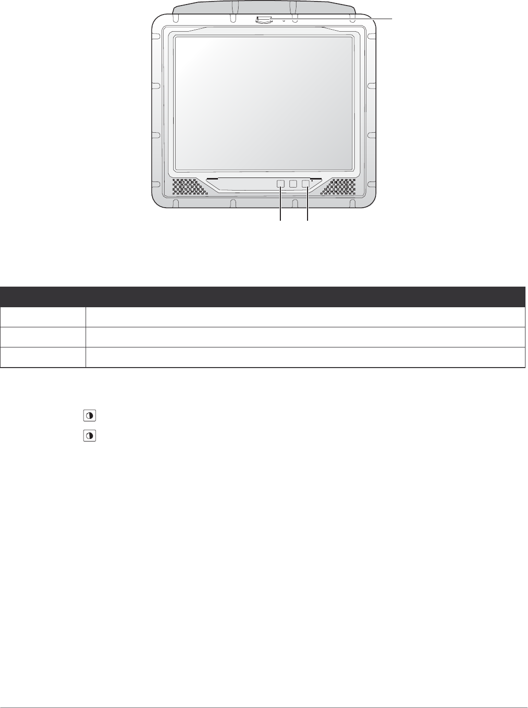
Figure 61. Brightness and Dimming Function
LED
LED Status
Table 8. LED Status
Brightness and Dimming Defrost/Defog
Color
Description
None Hyper dimming mode or shut down.
Green Normal.
Red Battery mode.
Adjust the illumination of the display to setup optimal conditions in Sunlight or Nigh mode
operations.
„
Press the button to decrease the illumination to Night mode.
„
Press the button to increase the illumination to Sunlight mode.
55
Operation
Calibrating the Touch Screen
The touch screens of all VM-521 devices that come delivered with an operating system (Windows
or Linux) are already calibrated.
You may need to calibrate your screen if you tap on one area and it registers in a different area of
the screen. Make sure you use the stylus to complete the alignment process.
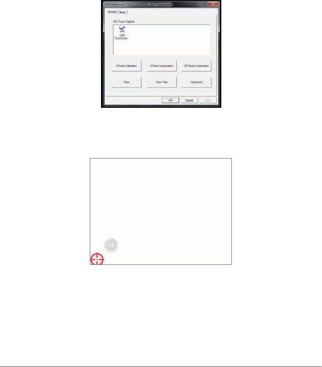
1. Tap Start > All Programs > HIDeGalaxTouch Tool > HIDeGalaxTouch Tool. The
HIDeGalaxTouch Tool appears.
Figure 62. HIDeGalaxTouch Tool
2. Tap 4 Points Calibration, 9 Points Linearization or 25 Points Linearization to begin the
process. The calibration process beings and calibration points are displayed on the screen.
3. Tap each calibration point as directed by the process.
Figure 63. Calibration Screen
56
Operation
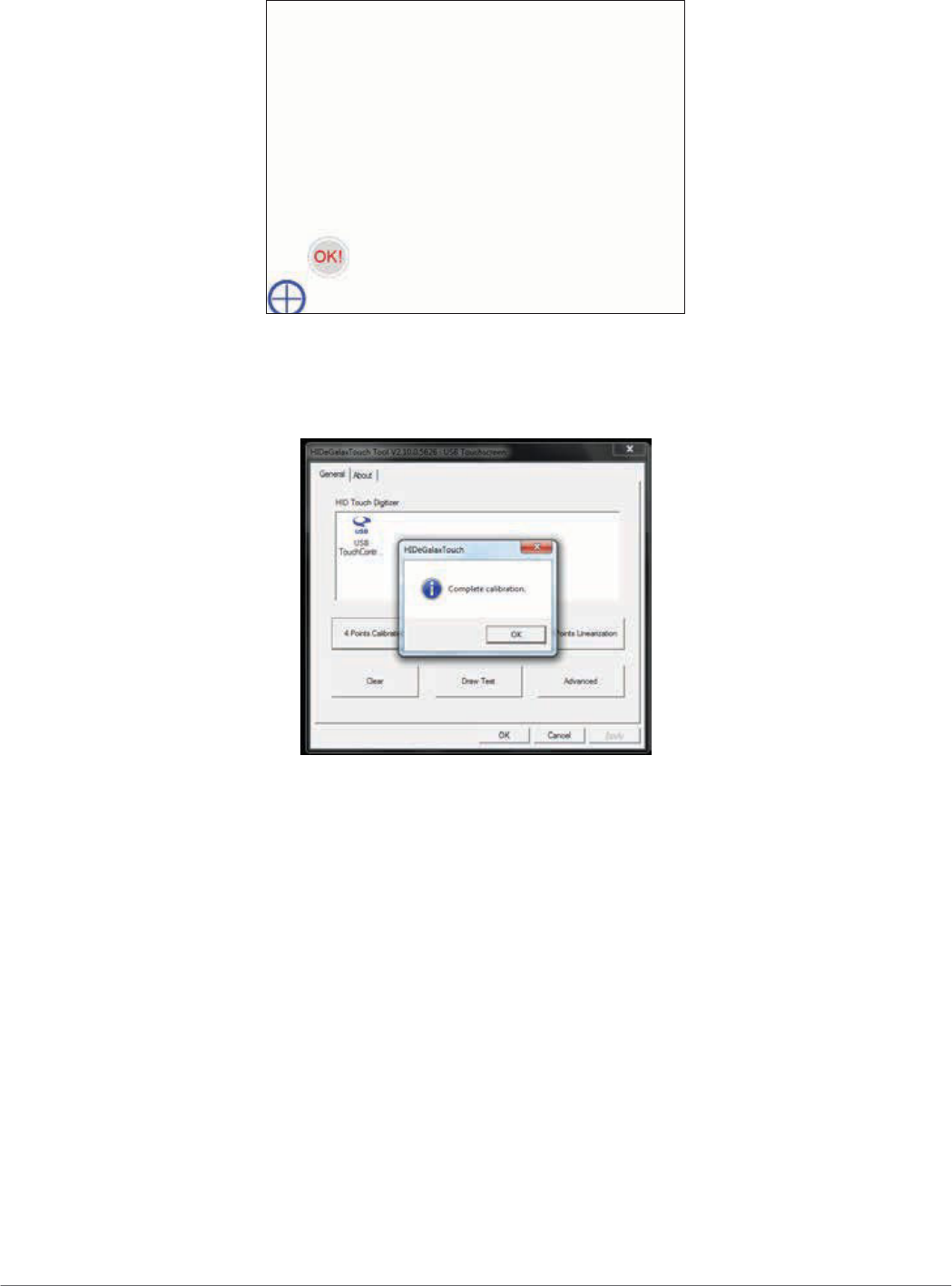
4. Tap and hold until the display shows OK.
Figure 64. Calibration Screen
5. Continue to follow the instructions until the process is finished.
6. Once calibration is achieved a prompt displays. Tap OK to complete the calibrate process.
Figure 65. Complete Calibrate
57
Operation
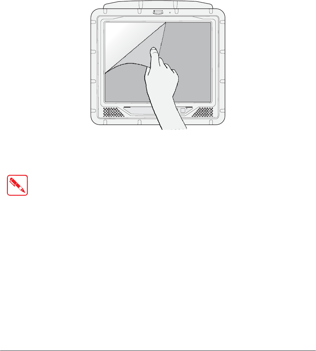
Protective Film
The front display of the VM-521 is protected during transport by the use of a transparent film.
This film should remain on the front display during assembly to avoid damage to the front display
surface.
Only remove the film after all of the assembly work has been completed.
Removing the Protective Film
Grasp the edge of the film to lift it up and pull it away from the screen.
Figure 66. Removing the Protective Film
Installing a New Protective Film
For instructions on installing a new protective film, see the documentation provided in the
protective sreen replacement kit.
Remove the existing protective film before installing a new one.
VM-521 Configuration Options
Date and Time
Use the following to set the Date and Time.
„
Press FN Key > press or tap Control Panel > Clock, Language an Region > Date and
Time
Power Management
Use the following to set the power management options.
„
Press FN Key > press or tap Control Panel > Hardware and Sound > Power Options
58

Operation
Speaker Volume
Use the following to set the speaker volume.
„
Press FN Key > press or tap Start > Control Panel > Hardware and Sound > Sound
Connect Bluetooth Devices
Use the following to set the speaker volume.
„
Press FN Key > press or tap Control Panel > Bluetooth Devices
Restart/Shutdown
Use the Windows interface to restart or shut down the VM-521.
„
To restart: Press FN Key > press or tap Start > arrow next to Shut down > Restart
„
To shut down: Press FN Key > press or tap Start > Shut down
59

Troubleshooting
Chapter 6.
Troubleshooting
Use the troubleshooting tables in this section to fix problems with the Wi-Fi connection, 802.1x
security, or general problems with operating the computer.
If you send the computer in for service, it is the user’s responsibility to save any data,
settings, and configuration. RuggON is only responsible for hardware when repairing
or replacing the device.
Troubleshooting the Wi-Fi Connection
Use this troubleshooting table to help solve problems with your 802.11 radio connection.
Q. When you turn on the computer after it was suspended for a while (10 to 15 minutes or
longer), it can no longer send or receive messages over the network.
A. Host may have deactivated or lost current terminal emulation session. In a TCP/IP direct
connect network, turn off the “Keep Alive” message from host to maintain the TCP session
while the computer is suspended.
Q. The computer is connected to the network and you move to a new site to collect data. Your
computer now shows you are not connected to the network.
A. Move closer to an access point or to a different location to reestablish communications until
you reconnect with the network.
Q. The computer appears to be connected to the network, but you cannot establish a terminal
emulation session with the host computer.
A. There may be a problem with the host computer, or with the connection between the access
point and the host computer. Check with the network administrator to make sure the host is
running and allowing users to log in to the system.
Q. The computer appears to be connected to the network, but the host computer is not receiving
any information from the computer.
A. There may be a problem with the connection between the access point and the host
computer. Check with the network administrator or use your access point user’s manual.
Q. A network connection icon appears in the toolbar, but then disappears.
A. The computer may not be communicating with the intended access point. Make sure the
network name matches the access point network name.
The access point may not be communicating with the server. Ensure the access point is
turned on, properly configured, and has 802.1x security enabled.
60

Troubleshooting 802.1x Security
Troubleshooting
Use the following table to troubleshoot problems with your 802.1x security that will prevent you
from connecting to your network, such as an incorrect password.
Q. The computer indicates it is not authenticated.
A. Make sure that:
„
The User Name and Password parameters on the computer must match the user name
and password on authentication server. You may need to reenter the password on both the
computer and authentication server.
„
On your authentication server, the user and group are allowed and the group policy is
allowed to log into the server. For help, see the documentation that shipped with your
authentication server software.
„
The IP address and secret key for access point must match the IP address and secret key
on the authentication server. You may need to reenter the IP address and secret key on both
your access point and authentication server. • the authentication server software is running
on the server PC.
Q. You receive a message saying “The server certificate has expired or your system date is
incorrect” after you perform a clean boot on the computer.
A. Date and time are not saved when you perform a clean boot. Reenter the date and time, and
then save your changes.
Troubleshooting Device Operations
Use this section to troubleshoot problems that may arise and keep you from operating the device
as instructed.
Q. What is happening? I press the Power button and nothing happens.
A. First, make sure the power cable is correctly connected to the device. If the power cable
is attached, check to see if the power cable is connected to the power source and that the
power source is functioning properly.
Q. My device is not responding. The screens appears to be frozen. What can I do?
A. Restart the computer.
Q. I am tapping the screen, but nothing is happening. Is there something I can do?
A. The touch screen may require re-calibration. For help, see “Calibrate the Screen” on page
17.
61

Troubleshooting
Call Product Support
If you cannot find the answer to your problem in the “Troubleshooting” section, you can visit the
RuggON technical knowledge base (Knowledge Central) at www.ruggon.com to review technical
information or to request technical support. If you still need help after visiting Knowledge Central,
you may need to call Product Support.
To talk to a RuggON Product Support representative, call:
1-800-755-5505
Before you can call RuggON Product Support, make sure you have the following information
ready:
„
Configuration number
„
Serial number
„
Operating system, BIOS, and MCU versions
„
Service pack version
„
System component versions
„
If you are using security, know the type and the full set of parameters
„
If you are using RuggON Terminal Emulator, know the version and protocol. If you are not
using RuggON Terminal Emulator, know the language your custom application was written in
and the tools you used to create it.
You can find most of the information listed above in RuggON Settings. Consult your application
developer for information on your custom application.
62

Chapter 7.
Maintenance
Cleaning the Device
Danger to electric shock when cleaning or maintaining the VM-521.
Maintenance
Housing
To avoid electric shock, turn the VM-521 off and disconnect it from the power supply before cleaning or
maintaining it.
„
The housing of the VM-521 is best cleaned with a damp cloth.
„
Use compressed air, a high-pressure cleaner or vacuum cleaner may damage the surface.
„
Use a high-pressure cleaner, the additional risk of water entering the VM-521 may damage
the electronics or touch screen.
Touch Screen
„
Use neutral detergent or isopropyl alcohol on a clean soft cloth to clean the panel surface.
„
Prevent using any kind of chemical solvent, acidic or alkali solution.
Returning the Device
Please put the contents in the original package gently when you need to return the VM-521.
Contacting RuggON
If you experience technical difficulties, please consult your distributor or contact the technical
services department:
www.ruggon.com
63
Technical Specifications
Appendix A.
Technical
Specifications
Port Pin Assignments
Use this section as a reference for the pin assignments of the various ports available on the
VM-521.
DIO Port
Figure 67. DIO Port Pin Assignment
1 5
6 10
Table 9. DIO Port Pin Assignments
11 15
Pin
Signal
1 Digital OUT-1
2 Digital OUT-2
3 Digital OUT-3
4 Digital OUT-4
5 Digital IN-1
6 Digital IN-2
7 Digital IN-3
8 Digital IN-4
9 No connected
10 No connected
11 No connected
12 No connected
13 No connected
14 GND
15 GND
64
Technical Specifications
RS-232 Port
By default, pin 9 is configured to provide +5V for an external bar code scanner, or it can be
configured to provide RI.
Figure 68. RS-232 Port Pin Assignment
1 5
6 9
Table 10. RS-232 Port Pin Assignments
Pin
Signal
Description
1 DCD Data carrier detect (input)
2 RXD Receive data (input)
3 TXD Transmit data (output)
4 DTR Data terminal ready (output)
5 GND Signal/power ground
6 DSR Data set ready (input)
7 RTS Request to send (output)
8 CTS Clear to send (input)
9 RI / PWR Bar code scanner power (300 mA max) or Ring indicator (input)
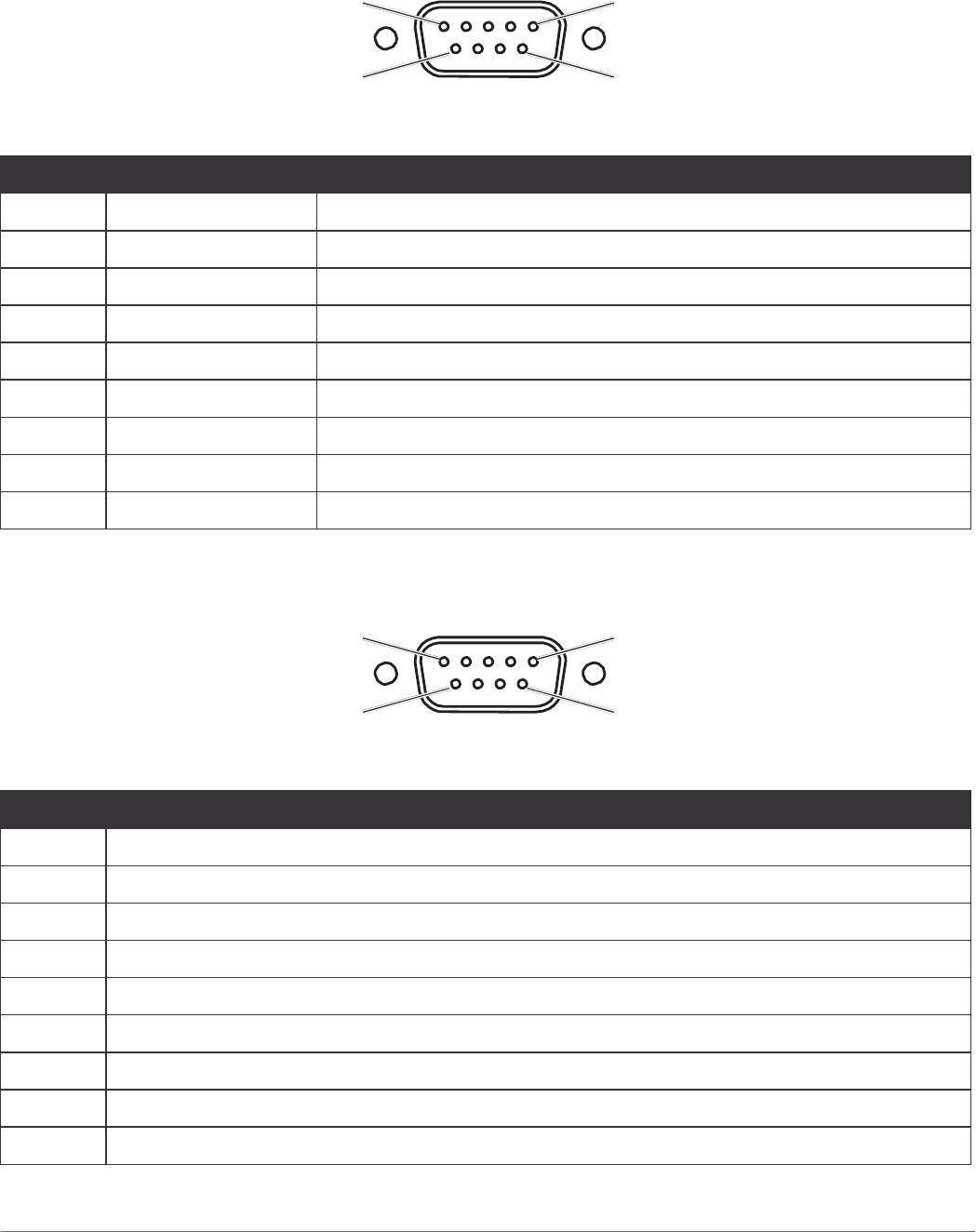
RS-422/RS-485 Port
Figure 69. RS-422/RS-485 Port Pin Assignment
1 5
6 9
Table 11. RS-422/RS-485 Port Pin Assignments
Pin
Signal
1 GND
2 RS485+
3 No connected
4 RS422_RX+
5 RS422_RX-
6 RS485-
7 No connected
8 RS422_TX+
9 RS422_TX-
65
Technical Specifications
CANBUS Ports
Figure 70. CANBUS Ports Pin Assignment
1 5
6 9
Table 12. CANBUS Ports Pin Assignments
Pin
Signal
Description
1 - No connected
2 CAN_L CAN_L bus line dominant low 5V level
3 GND Ground
4 - No connected
5 - No connected
6 - No connected
7 CAN_H CAN_H bus line dominant high 5V level
8 - No connected
9 - No connected
66

Technical Specifications
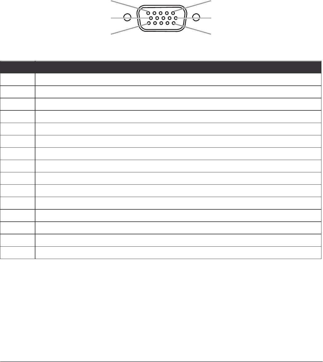
Expansion Port
Figure 71. EXPANSION Port Pin Assignment
1 5
6 10
11 15
Table 13. EXPANSION Port Pin Assignments
Pin
Signal
Description
1 CH1: Audio Left Audio left input
2 CH2: Video Video input
3 CH2: Audio Right Audio right input
4 NC No connected
5 CH3: Audio Right Audio right input
6 CH1: Video Video
7 CH1: Audio Right Audio right input
8 CH2: Audio Left Audio left input
9 CH3: Video Video
10 CH3: Audio Left Audio left input
11 CH4: Video Video
12 GND GND
13 CH4: Audio Left Audio left input
14 CH4: Audio Right Audio right input
15 GND GND
67
Technical Specifications
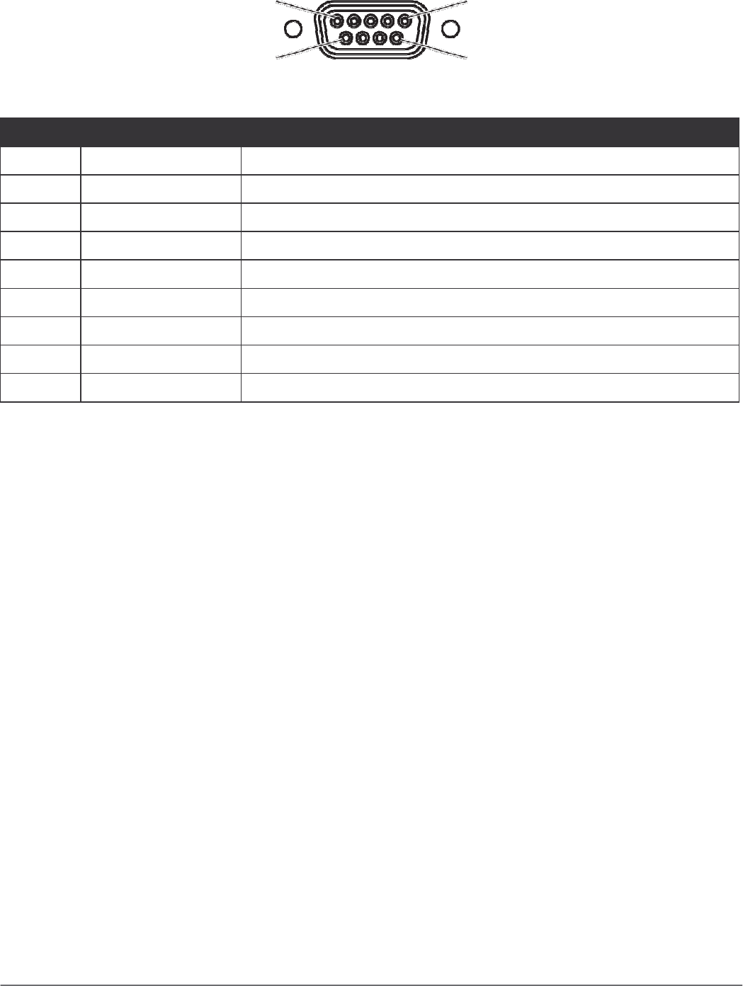
USB Port
Figure 72. USB Port Pin Assignment
1 5
6 9
Table 14. USB Port Pin Assignments
Pin
Signal
1 USB2_D-
2 USB2_D+
3 GND
4 USB1_D+
5 USB1_D-
6 GND
7 USB2_PWR
8 USB1_PWR
9 Not used
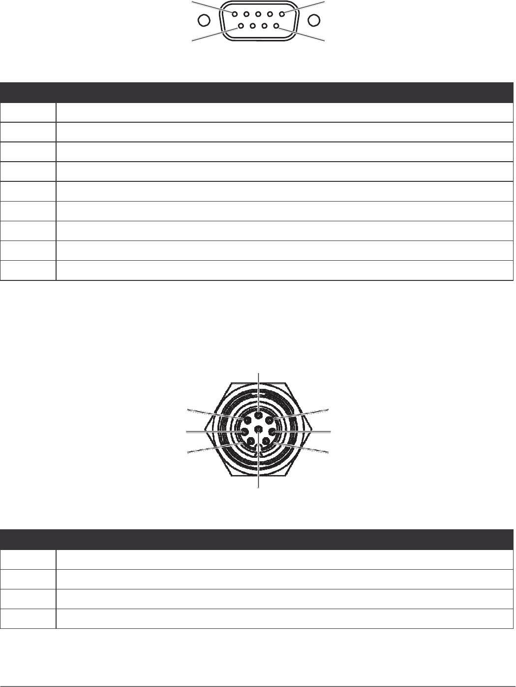
Power Connector
If you are connecting to an external DC/DC supply, you must apply power to DC+. If you are
connecting to 10 to 60V vehicle power, connect power to V In+.
Figure 73. Power Connector
2
1 3
4 5
6 8
7
Table 15. Power Connector
Pin
Signal
1 POWER
2 GND
3 GND
4 POWER
68