Runcom Communications CPETVWS-1 CPE-CPE-O-R-WS User Manual
Runcom Technologies Ltd. CPE-CPE-O-R-WS
Contents
- 1. User Operational Manual
- 2. User Manual
User Manual

our product manager
TVWS
FCC ID: XYMCPETVWS-1
CPE-O-R-WS
User and Installation Manual
Doc: RUNCOM CPE-O-R-WS USER MANUAL RN–PMG-300516 V-1.3

Preface Material CPE-O-R-WS User and Installation Manual
i Runcom Technologies Ltd.
About this Guide
This User Manual describes the procedures for commissioning, mounting, installing and managing the CPE-O-R-
WS.
Notice
This document contains proprietary and confidential material of Runcom Ltd. Any unauthorized reproduction, use
or disclosure of this material, or any part thereof, is strictly prohibited. This document is solely for the use of
Runcom Ltd. employees and authorized Runcom Ltd. customers.
The material furnished in this document is believed to be accurate and reliable. However, no responsibility is
assumed by Runcom Ltd. for the use of this material. Runcom Ltd. reserves the right to make changes to the
material at any time and without notice.
All other trademarks are the property of their respective owners. Other company and brand products and service
names are trademarks or registered trademarks of their respective holders.
Safety Precautions
To avoid injury and to prevent equipment damage, observe the safety precautions below.
Only qualified personnel should be allowed to install, replace, and service the equipment. The
device cannot be sold retail, to the general public or by mail order. It must be sold to dealers.
Installation must be controlled. Installation must be performed by licensed professionals.
Installation requires special training. The Runcom radios and antennas should be installed ONLY
by experienced installation professionals who are familiar with local building and safety codes
and, wherever applicable, are licensed by the appropriate government regulatory authorities.
Failure to do so may void product warranty and may expose the end user or the service provider
to legal and financial liabilities.
Always observe standard safety precautions during installation, operation and maintenance of
this product.
This equipment must be installed according to country national electrical codes.
Any changes and modifications to the device and the accessories must be approved by Runcom.
All equipment and accessories must be installed in a restricted access area.
Observe all the labels on the equipment, providing operation details and warnings.
Read and follow the installation instructions provided in this manual.
The CPE should be positioned more than 2 meters from humans.
In case of using cables that are not provided with the equipment package, ensure these cables
comply with the regulatory inspection authorities and are the responsibility of the customer.
Do not move or ship equipment unless it is properly packed in its original wrapping and shipping
containers.
Electrical Shock Prevention
When connecting equipment to the AC and DC voltage supplies, ensure proper polarity.
Disconnect the power source before installing or maintaining the power wiring.
Do not operate the equipment if there is any failure or damage to electrical components.
Do not touch exposed connections, components or wiring when power is on.
Install the equipment and the grounded DC supply circuits in adjacent cabinets.
Protect the DC power source with an adjacent circuit breaker.
The equipment must be properly grounded before attempting to operate or perform any repairs.

CPE-O-R-WS User Manual Preface Material
Runcom Technologies Ltd. ii
RF Exposure
To comply with FCC Section 1.310 for human exposure to radio frequency electromagnetic
fields, implement the following instruction:
A distance of at least 200cm between the equipment and all persons should be
maintained during the operation of the equipment.
Radio Interference
This equipment generates and radiates radio frequency energy and if not installed and used in
accordance with the instruction manual, may cause interference to radio communications.
To avoid interferences:
Avoid conjunction with any other antenna or transmitter.
In case of Radio Interference: Relocate the antenna and Increase separation between the
equipment and the receiver (e.g. connect to a separate circuit or outlet).
When using an external antenna, the external antenna must not be co-located or operating in
conjunction with any other antenna or transmitter
NOTE: This equipment has been tested and found to comply with the rules for TV band device, pursuant to part
15 of the FCC Rules. These limits are designed to provide reasonable protection against harmful interference in a
residential installation. This equipment generates uses and can radiate radio frequency energy and, if not installed
and used in accordance with the instructions, may cause harmful interference to radio communications. However,
there is no guarantee that interference will not occur in a particular installation. If this equipment does cause
harmful interference to radio or television reception, which can be determined by turning the equipment off and on,
the user is encouraged to try to correct the interference by one or more of the following measures:
-Reorient or relocate the receiving antenna.
-Increase the separation between the equipment and receiver.
-Connect the equipment into an outlet on a circuit different from that to which the receiver is connected.
-Consult the dealer or an experienced radio/TV technician for help.
NOTE: THE GRANTEE IS NOT RESPONSIBLE FOR ANY CHANGES OR MODIFICATIONS NOT EXPRESSLY
APPROVED BY THE PARTY RESPONSIBLE FOR COMPLIANCE. SUCH MODIFICATIONS COULD VOID THE
USER’S AUTHORITY TO OPERATE THE EQUIPMENT.
Warning: THE CPE-O-R-WS EQUIPMENT SHALL BE INSTALLED AT A HEIGHT
NO GREATER THAN 30 METERS ABOVE THE GROUND
.
Note:
THE CPE-O-R-WS EQUIPMENT SHALL BE OPERATED ONLY IN CONJUNCTION WITH
THE AFAS SOFTWARE THAT CONNECTS THE CPE TO THE TVWS DATA BASE

CPE-O-R-WS User Manual
Runcom Technologies Ltd. 1
Table of Contents
1 Introducing CPE-O-R-WS .................................................................................................... 4
2 CPE-O-R-WS Overview ....................................................................................................... 5
2.1 Interfaces Specifications ................................................................................................................. 5
2.1.1 User Interface Specification ................................................................................................... 5
2.1.2 TVWS Interface Specification ................................................................................................ 6
2.1.3 Operational Description ........................................................................................................ 6
3 Getting Started..................................................................................................................... 7
3.1 Packing list .................................................................................................................................. 7
3.2 Unpacking the Equipment ............................................................................................................... 7
3.3 Operating and Configuration of the CPE-O-R-WS ............................................................................... 8
3.3.1 Device Logic connection ....................................................................................................... 8
3.3.2 CPE Configuration ............................................................................................................... 8
3.4 CPE-O-RS-WS Registration (in the Data Base) and Configuration (prior to installation) ............................. 9
3.4.1 CPE Network ...................................................................................................................... 9
3.4.2 Registration of the CPE-O-RS-WS in the Data Base (Spectrum Bridge) ......................................... 9
3.4.3 CPE-O-RS-WS relocation ................................................................................................... 10
3.4.4 Adding of CPE-O-RS-WS to the AFAS ................................................................................. 10
3.5 Preparations before physical installation .......................................................................................... 12
3.5.1 Skills Required .................................................................................................................. 12
3.5.2 Information Needed before .................................................................................................. 12
3.5.3 Required Tools and Equipment ............................................................................................. 12
3.5.4 Performing a Site Survey..................................................................................................... 13
3.6 Installing the Equipment ............................................................................................................... 13
3.6.1 Device Logic connection ..................................................................................................... 13
3.6.2 Installing Outdoor Unit (ODU) ............................................................................................. 13
3.6.3 CPE Connection to the PoE adapter ....................................................................................... 14
3.6.4 Sequence for Interconnect Cable ........................................................................................... 14
4 Managing CPE Devices ...................................................................................................... 16
4.1 General ..................................................................................................................................... 16
4.2 Accessing CPE via Web Brower .................................................................................................... 16
4.2.1 Access CPE from LAN Segment .......................................................................................... 16
4.2.2 Access CPE Device from WAN Segment ............................................................................... 17
4.3 CPE LAN Side Network configuration ............................................................................................ 18
4.3.1 Router / Bridge selection ..................................................................................................... 18
4.3.2 DHCP ............................................................................................................................. 19
4.3.3 LAN IP settings ................................................................................................................. 19

CPE-O-R-WS User Manual
2 Runcom Technologies Ltd.
4.4 CPE WAN Side Network configuration ............................................................................................ 20
4.4.1 WAN interface enabling ...................................................................................................... 20
4.4.2 WAN IP Address Settings .................................................................................................... 20
4.4.3 DNS IP Address Settings ..................................................................................................... 21
4.5 LAN access control ...................................................................................................................... 21
4.6 Radio Control.............................................................................................................................. 23
4.6.1 Radio Transmission Enable .................................................................................................. 23
4.6.2 Radio Signal Transmission ................................................................................................... 23
4.7 Operation Channels Frequency Control ............................................................................................ 24
4.7.1 Adding Allowed Channels.................................................................................................... 24
4.8 Controlling CPE access ................................................................................................................. 25
4.9 Viewing CPE status Information ..................................................................................................... 26
4.9.1 Running Information ........................................................................................................... 26
4.9.2 WiMAX Information .......................................................................................................... 26
4.9.3 LAN Information ............................................................................................................... 27
4.9.4 Traffic Statistic Information ................................................................................................. 27
4.10 Viewing Wireless status and Information .......................................................................................... 28
4.10.1 Networking Status .............................................................................................................. 28
4.10.2 WiMAX Data Statistics ....................................................................................................... 29
4.10.3 Hardware Information ......................................................................................................... 29
5 MAX Rx Signal Adjusting ................................................................................................... 30
5.1 RF Signal Adjusting ..................................................................................................................... 30
5.2 Link Status ................................................................................................................................. 30
5.2.1 Networking Status .............................................................................................................. 30
5.2.2 WiMAX data statistics and Hardware information .................................................................... 31
5.3 Welcome WEB Page .................................................................................................................... 31
5.4 LED Display ............................................................................................................................... 32
Figures and Tables
Figure 1: WiMAX CPE Application in 802.16e Network ................................................................. 4
Figure 2: CPE Equipment Photo ................................................................................................. 5
Figure 3: Package Equipment Photo ............................................................................................ 7
Figure 4: PoE Connectivity....................................................................................................... 8
Figure 5: AFAS Site administration page ................................................................................. 10
Figure 6: AFAS Select CPE page .............................................................................................. 10
Figure 7: AFAS CPE configuration page................................................................................... 11
Figure 8: AFAS CPE available channels request ....................................................................... 11
Figure 9: Pole Mount Diagram ................................................................................................. 14
Figure 10: CPE - Ethernet Header Connection ............................................................................. 14
Figure 11: RJ45 Pin Diagram ................................................................................................... 15
Figure 12: Logon Web Pages ................................................................................................... 17
Figure 13: LAN Network Configuration ..................................................................................... 18
Figure 14: WAN Network Configuration.................................................................................... 20

CPE-O-R-WS User Manual
Runcom Technologies Ltd. 3
Figure 15: Access Control Configuration ................................................................................... 21
Figure 16: WiMAX Radio Control............................................................................................ 23
Figure 17: Operation Channels Frequency Control ....................................................................... 24
Figure 18: Device Access options ............................................................................................. 25
Figure 19: CPE Status Information ........................................................................................... 26
Figure 20: Traffic Data Counters .............................................................................................. 27
Figure 21: WiMAX Interface Status and Information .................................................................... 28
Figure 22: Signal Indicators .................................................................................................... 30
Table 1: LAN Interface Specification ......................................................................................... 5
Table 2: TVWS Interface Specification ....................................................................................... 6
Table 3: Packaging List .......................................................................................................... 7
Table 4: Required Tools and Extra Equipment ........................................................................ 12
Table 5: PoE Specification ..................................................................................................... 14
Table 6: Ethernet RJ45 Cable Specification ............................................................................... 15
Figure 7: Led Diaplay ............................................................................................................ 32
CPE-O-R-WS User Manual
4 Runcom Technologies Ltd.
1 Introducing CPE-O-R-WS
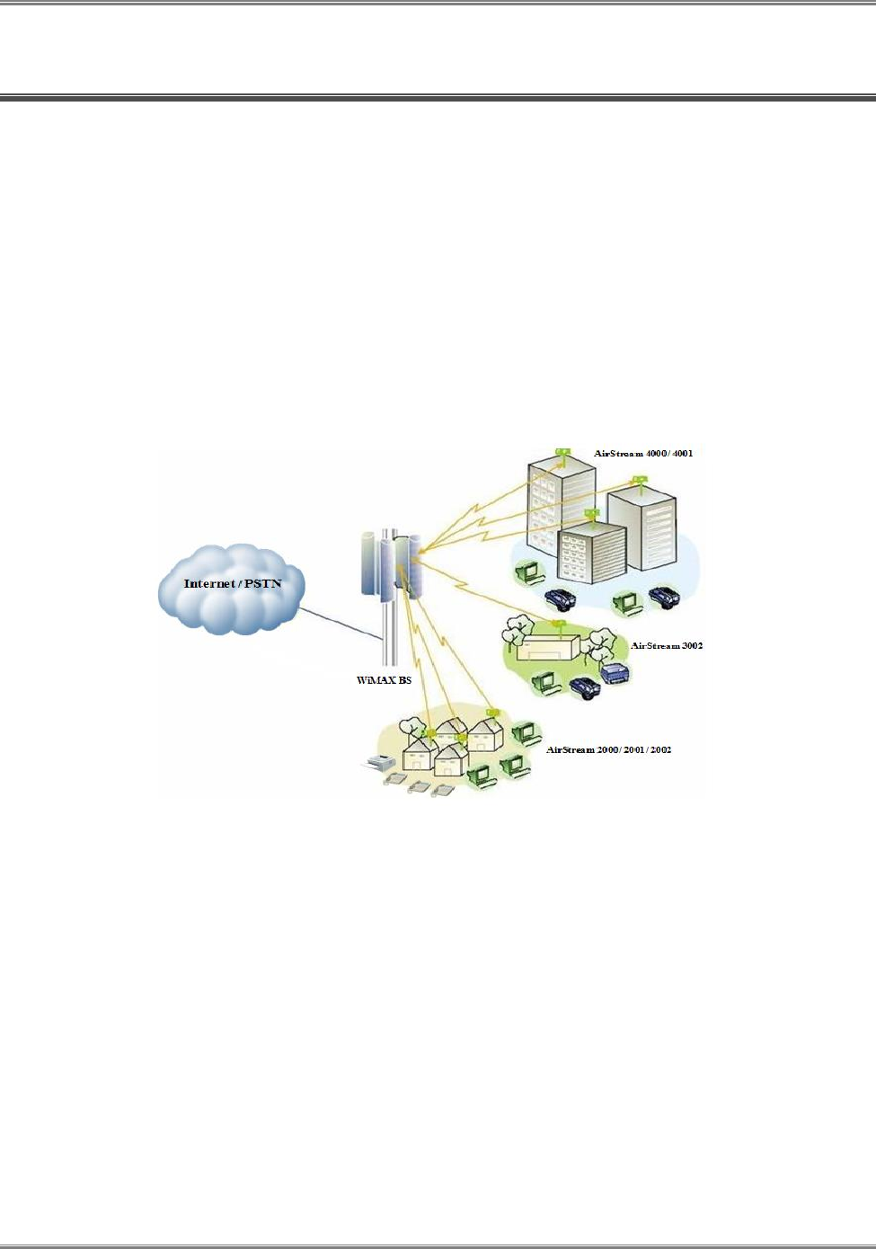
Runcom’ s CPE-O-R-WS terminal is a WiMAX CPE product 802.16e WAVE II compliant terminal that
was adapted to the TVWS market according to the FCC regulations for use as a fixed device.
Both indoor and outdoor models are available for different application environment needs and the end
customer can chose a variety of product models with different user interfaces. The CPE can also support multiple
frequency bands to meet different operator or country deployment needs. The sophisticated QoS feature also helps
service providers to better control data traffic in their wireless networks. All CPE products are equipped with advance
capability to differentiate end user traffic, marks traffic with different priorities, and policing traffic at the edge of their
networks. These capabilities are vital for service providers to avoid service disruption caused by malicious users.
The CPE products provide multiple management interfaces to allow local or over the air provision and management of
the device. The supported user management interface and management protocol include WEB, FTP, TFTP and future
TR-069. Runcom also offers a standard alone device management solution for device auto provision, firmware
management and remote monitoring and maintenance. A north bound API is available for quick integration with
operator OSS/BSS platform.
Figure 1: WiMAX CPE Application in 802.16e Network
This manual provides user reference information necessary for configuration and provisioning of CPE-O-R-WS
products. It can also be used by technical support engineers for troubleshooting and problem resolution.
CPE-O-R-WS User Manual
Runcom Technologies Ltd. 5
2 CPE-O-R-WS Overview
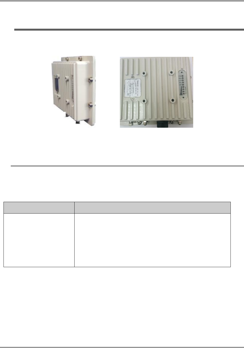
Figure 2: CPE Equipment Photo
2.1 Interfaces Specifications
2.1.1 User Interface Specification
Table 1: LAN Interface Specifications
Model
Description & User Interface
CPE-O-R-WS
- External antenna
- 1 RJ45 10/100M LAN Port
- PWR, RUN, LAN, and WiMAX (1-4) LEDs
- 24V DC PoE supply, ODU Power < 11 Watts
- Dimensions: 220 mm (L) × 220 mm (W) × 70 mm (D)
- Weight: Less than 3Kg

CPE-O-R-WS User Manual
6 Runcom Technologies Ltd.
2.1.2 TVWS Interface Specification
Table 2: TVWS Interface Specifications
Frequency Bands
470-698MHz
Radio Access
802.16e Wave 2
Operation Mode
TDD
Channel Bandwidth
6 MHz
Output Power
24 dBm at antenna port
Modulation
QPSK, 16QAM, 64QAM for DL and QPSK, 16QAM for UL
FFT
512 FFT points
FEC
Convolution Code and Turbo Code
Authentication
TTLS and TLS
2.1.3 Operational Description
The CPE-O-RS-WS is operated as part of a TVWS Network. The CPE is used to provide connectivity
(Internet Access) to users using Broadband Wireless Access based on WiMAX technology.
The TVWS Network uses the TV White Space spectrum (470-698 MHz) in channels that are not used by
licensed or protected users such as broadcasters and wireless microphones.
The CPEs are wirelessly connected to Base Stations (RNU4000-BTS) that are usually installed in high
places such as tower, water tanks , rooftops, etc. and from the Base Stations the communication is relayed
to the Internet cloud via a gateway/router ( Micronoc, CompactNOC, ASN Gateway, etc.). The CPE is
connected through the Base Stations to the Automatic Frequency Allocation Software (AFAS) in order to
receive the available TVWS channels from the TVWS Data Base. The CPE will only transmit after it is
synchronized to the Base Station on a channel allocated by the TVWS Data Base via the AFAS SW
The CPE uses OFDMA technology in TDD (Time Division Duplexing) mode with adaptive modulation in
order to provide a reliable connectivity, the CPE modulation will change automatically according to the
link budget between the CPE and the Base Station. The available modulation levels are described in Table
2 above.
The CPE will adapt automatically its output power level according to the link budget between the CPE
and the Base Station in order to reduce self-interference. In addition the CPE is GPS synchronized with
the Base Station and other CPE’s in the area connected to the same TVWS Network in such a way that all
CPE’s will transmit and receive at the same time, the GPS synchronization mitigates the self-interference
between the CPE’s in the same network
The CPE can be connected at the customer’s premises via POE to any IP device that needs Internet
connectivity such as Wi-Fi routers, laptop/desktop computers, IP switches, etc.
CPE-O-R-WS User Manual
Runcom Technologies Ltd. 7
3 Getting Started
3.1 Packing list
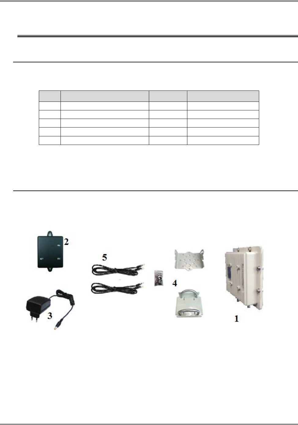
Upon receiving the product, unpack the product package carefully. Each product is shipped with the following items:
Table 3: Packing List
Outdoor CPE Products
Quantity
Note
1
ODU unit
1
All
2
PoE adapter
1
All
3
24V DC Power Adapter
1
All
4
Mounting brackets
1
All
5
PC Ethernet Cable
1
All
If you find any of the items is missing, please contact our local distributor immediately.
3.2 Unpacking the Equipment
Table 4 lists all the standard parts that are supplied in your CPE-O-R-WS Unit Installation Package. Please take the time
to unpack the package and check its contents against this list.
Figure 3: Package Equipment Photo
CPE-O-R-WS User Manual
8 Runcom Technologies Ltd.
3.3 Operating and Configuration of the CPE-O-R-WS
3.3.1 Device Logic connection
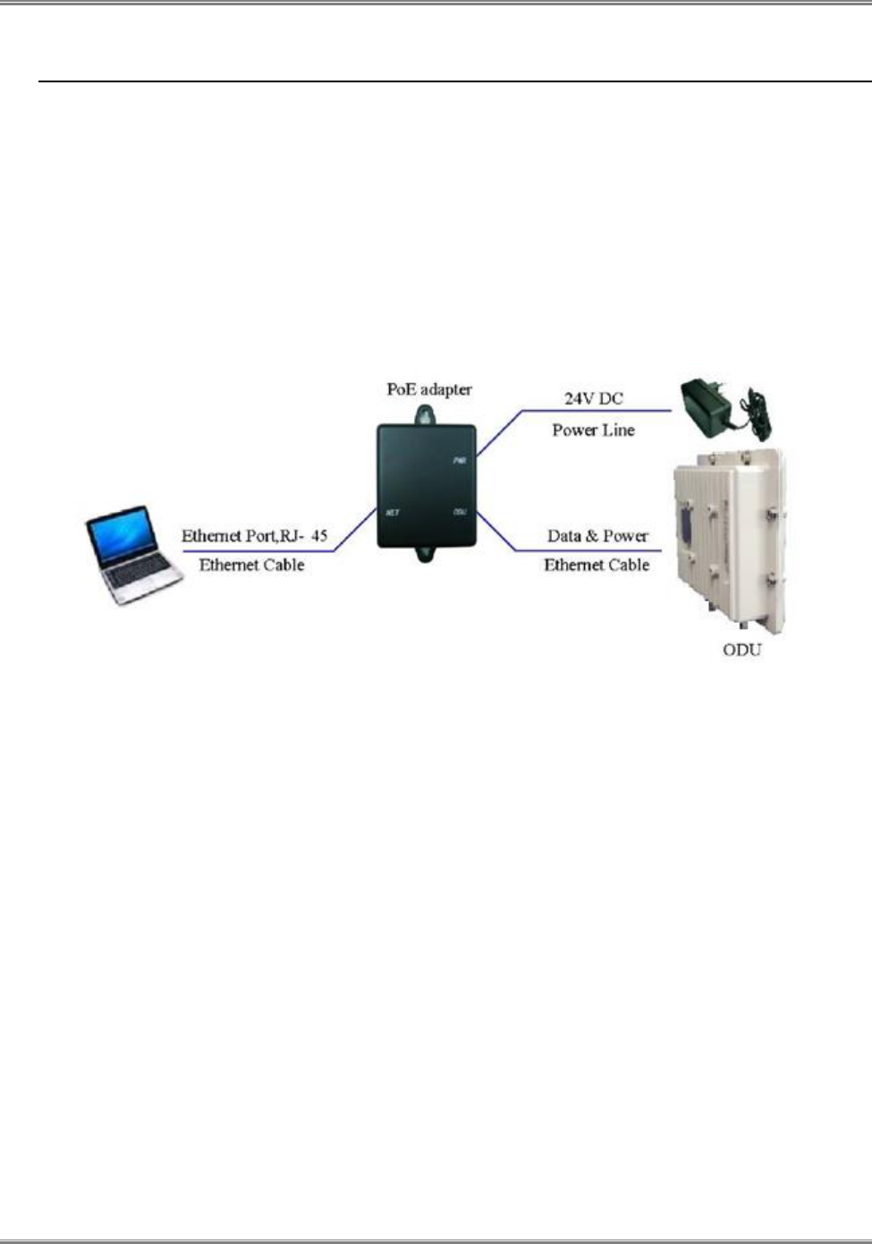
Connect the CPE to the PoE adapter port ODU using a standard CAT 5 Ethernet cable. The CPE is powered from a 24V
DC power supply from a power adapter. The power adapter operates from 90-250V AC range. Once the device is
powered, the user should wait for about 2 minutes before the device becomes operational. For CPE with the RUN LED
indicator, a slowly flashing light indicates the system has completed the startup procedure.
To connect PC, LAN switch or other type of IP device to the CPE product, connect a standard CAT5 Ethernet cable and
connect to the NET port of the PoE. Once it is connected the CPE LAN LED indicator should come on.
Figure 4: PoE Connectivity
3.3.2 CPE Configuration
Connect Laptop to the Net port of the PoE and open Google Chrome Browser. Connect to IP 192.168.0.1 and
follow the instruction in paragraph 4 to configure the CPE, to the required channel frequency obtained by AFAS
from the TVWS Data Base.
Warning! – use discrete channels settings only!

CPE-O-R-WS User Manual
Runcom Technologies Ltd. 9
3.4 CPE-O-RS-WS Registration (in the Data Base) and
Configuration (prior to installation)
3.4.1 CPE Network
The CPE-O-RS-WS shall be used only in a TVWS network with Runcom AFAS Software and RNU-4000TVWS
Base Stations (FCC Identifier: XYMBSTVWS-1) and cannot operate with any other base station.
3.4.2 Registration of the CPE-O-RS-WS in the Data Base (Spectrum Bridge)
Prior the installation of the CPE-O-RS-WS, the professional installer shall register the CPE-O-RS-WS in the
Spectrum Bridge TVWS Data Base. The Registration includes the CPE-O-RS-WS MAC ID, the location Latitude
and Longitude, antenna height, and Base Station ID to where the CPE-O-RS-WS will be connected. All this will
be done using the AFAS (Automatic Frequency Allocation Software).
Runcom Automated Frequency Allocation Software (AFAS) is a SW element that mediates between the TV white
space (TVWS) database and Runcom Base Stations (BTS) and user terminals (CPE), in order to comply with FCC
rules.
The AFAS main tasks are to register the TVWS fixed devices (Base Station and CPE’s) to the TVWS Data Base,
to receive the available channels from the Data Base to each one of the fixed devices registered and to disable the
operation of the fixed devices in a TVWS channel that is no longer available or due to a communication failure
between the AFAS and the Data Base.
The AFAS Software is connected to the CPE through the Wireless Connection between the Base Station and the
CPE.
The CPE registration is done according to the procedure described in paragraph 3.4.4 below
After the registration, if the CPE is allowed by the Data Base to operate in this location, the AFAS will receive
from the TVWS Data Base the list of free channels that can be used in this location, and the operator shall
configure the CPE-O-RS-WS with those channels.
Note- The location and height of the CPE will be obtained by an accurate device ( >95%) such as GPS, or Google
Earth application.
Installation Process: Following the Registration process, the professional installer should proceed to the
physical installation of the CPE at the designated site at the location (Latitude, Longitude and height) registered in
the Data Base. The physical installation should be according to paragraph 3.5 and 3.6 of this Manual
Turn on Process: After the physical installation the CPE-O-RS-WS is turned on and a link is established in
one of the configured TVWS channels (the channel that the Base Station operates in), the management of the CPE-
O-RS-WS will be done over the air by the AFAS software over an IP network.
AFAS connects every T hours (T<= 24 hours) with Spectrum Bridge (SB) TVWS database and retrieves for each of
its related TVWS fixed devices (Base Stations and CPE-O-RS-WS) in its network an updated set of available TVWS
channels.
One of the channels of this set will be selected automatically by AFAS for use in the Base Station (RNU4000-TVWS)
and its related CPEs.
There is no possibility for the Base Station and its related CPEs to operate on any other channel which is not listed
in the last updated set of available TVWS channels.
In case that the CPE available channels will not coincide with the Base Station available channels the AFAS, or in
case the AFAS is disconnected from the Data Base the CPE will turn off its transmitter by the AFAS and the CPE
CPE-O-R-WS User Manual
10 Runcom Technologies Ltd.
will not be able to transmit again until it will be synchronized with the Base Station in a new channel allocated by
the TVWS Data Base via AFAS
3.4.3 CPE-O-RS-WS relocation
In case the CPE is relocated to a different location than the location registered in the Data Base, the installer shall do
a new registration according to paragraph 3.4.4 below prior to turning on the relocated CPE. The relocation must be
to a new location that is covered by a registered TVWS Base Station.
3.4.4 Adding of CPE-O-RS-WS to the AFAS
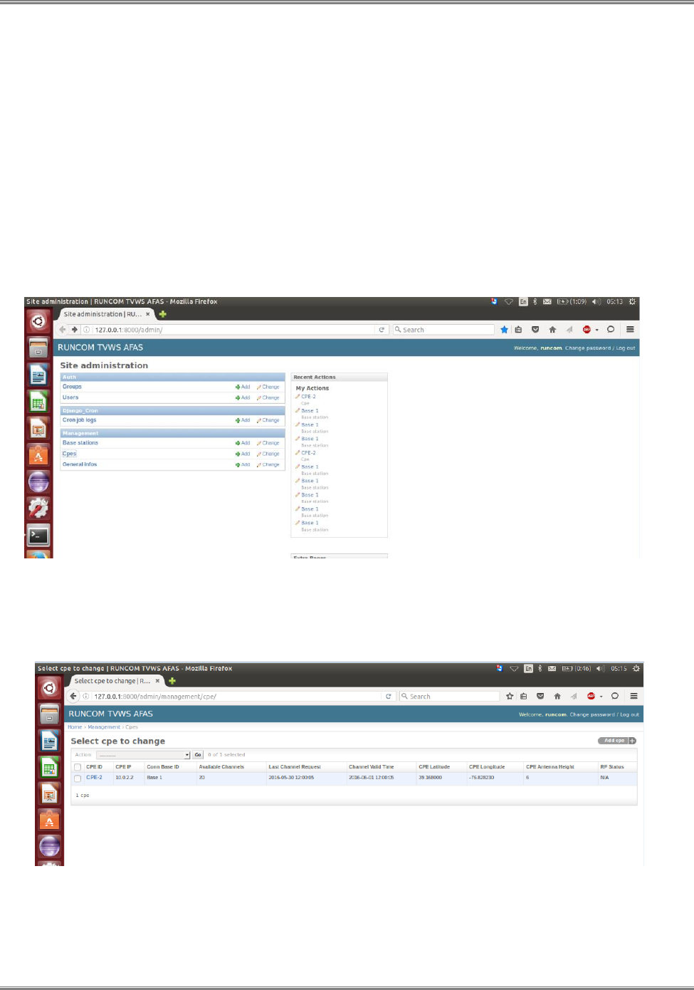
To add a CPE in the AFAS open the “Site administration” page in the AFAS and Choose CPE as shown in
Figure 3 below.
Figure 5: AFAS Site administration page
The AFAS SW will open the “Select CPE” page, on this page click the “Add cpe” option as shown in figure 4 below.
Figure 6: AFAS Select CPE page
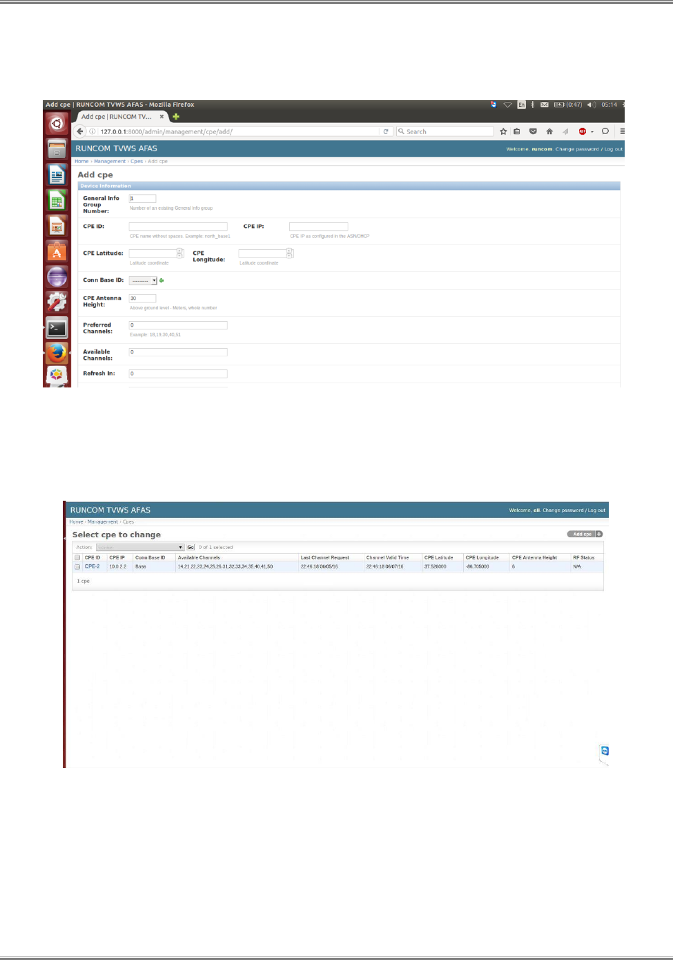
On the “Add cpe” page fill the CPE ID, CPE IP, CPE Latitude and Longitude, the Connecting Base ID, The CPE
antenna Height, MAC ID and save it as shown in Figure 5 below:
CPE-O-R-WS User Manual
Runcom Technologies Ltd. 11
NOTE: Each CPE MAC ID will have one set of location data (Latitude, Longitude and Antenna Height) associated
to it at the AFAS
Figure 7: AFAS CPE configuration page
After completion of entering the information in the “Add cpe page” click the "Channel request to select Devices"
and press "Go" and the AFAS will ask for channels from the Data Base as shown in Figure 6 below.
Figure 8: AFAS CPE available channels request
After receiving the available channels from the Data Base, AFAS will load the allowed channels to the CPE and the
CPE will establish the link with the Base Station in one of the allowed channels.

CPE-O-R-WS User Manual
12 Runcom Technologies Ltd.
3.5 Preparations before physical installation
3.5.1 Skills Required
The CPE-O-RS-WS shall be installed by a professional installer that was qualified to install TVWS equipment.
It is forbidden to install the CPE-O-RS-WS by non-professional installer.
3.5.2 Information Needed before
The professional installer shall gathered the following information prior to the installation
Locations of the Base Station and the azimuth from the CPE to the Base Station, which you should be able to
connect to.
Log in account and password
3.5.3 Required Tools and Equipment
This section lists all the extra tools and equipment mentioned in this guide that you will need to perform the installation.
None of the items listed in Table 2-1 are supplied with the kit, so make sure you gather everything you need before you
start. Use the table below to check exactly what you will need (this will depend on where you are going to install the
outdoor transceiver).
Table 4: Required Tools and Extra Equipment
Tools Required
Extra Equipment Required
Compass
Grounding clamp
Area map with an accurate direction
legend showing magnetic north
Grounding wire
Flat-head screwdriver
Roll of UTP CAT 5 cable
Hammer or mallet
Cable clip
Power drill
Anchor sleeves
1/8 inch drill bit
RJ-45 connectors (plastic bodied)
3/16 inch, 4mm hex (Allen) wrench
1 inch copper tape
Bubble level or plumb line
Adjustable wrench
Crimping tool (must be specifically
matched for the RJ-45 connector used)
Wire stripper
Small wire cutters
Punch down tool

CPE-O-R-WS User Manual
Runcom Technologies Ltd. 13
3.5.4 Performing a Site Survey
This section explains how to select the best location for mounting the outdoor CPE. The steps you will perform are:
Determine the direction of available Base station from the house or building.
What You Need
Compass.
Area map with an accurate direction legend showing magnetic north.
TVWS Base station location.
TVWS Base station and CPE Location
While installing the unit, you need to determine the direction of the Base Station from the house or building.
a) Use the compass to determine the Base Station direction.
b) Find on the customer premises the best place to install the CPE. It is recommended on the TV mast if exist.
Warning: The CPE-O-R-WS equipment shall be installed at a height no greater than 30 meters above the ground.
c) Turn the CPE antenna to the Base Station direction and adjust tilt it up and down and to the right and to the left side
to obtain maximum signal. Perform this antenna align process if a second antennas is used
d) Use a Laptop with WEB connected to the PoE to read the RSSI and CINR that the CPE receive.
e) If the signal is not good try to move and find a better location where the RSSI and CINR will be better.
f) Record the Latitude and Longitude of the CPE installation location using a digital compass and update it in the
AFAS if it is different from the registration per paragraph 3.4.2 above.
3.6 Installing the Equipment
3.6.1 Device Logic connection
For outdoor CPE product, it is suggested that the CPE device be installed in a shaded area to avoid direct sun light
exposure which may cause over heat in certain extreme weather condition.
The CPE should be properly grounded for proper protection against lighting or power surge.
The CPE-O-R-WS is powered by 24V DC over a CAT5 Ethernet cable by a PoE device. The power is from a power
adapter that operates in 90-250V AC range. The PoE and the power adapter are indoor units and need to be located in
the house or office. Fix the PoE device near an electrical outlet. User Ethernet are provided via the PoE adapter too.
3.6.2 Installing Outdoor Unit (ODU)
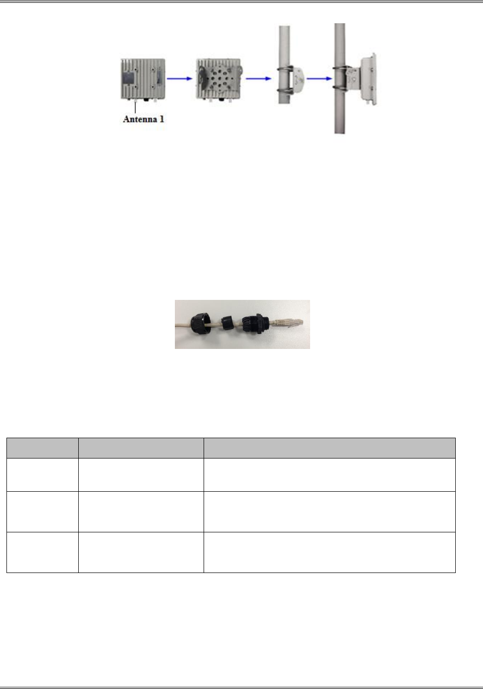
The CPE-O-R-WS can be mounted on a pole or on the wall. Fix the CPE and the antenna and connect the antenna
to the CPE using a coax cable. Connect the coax cable to Antenna 1 on the CPE.
CPE-O-R-WS User Manual
14 Runcom Technologies Ltd.
Figure 9: Pole Mount Diagram
Warning! – The CPE should be properly grounded for proper protection against
lightning or power surge!
3.6.3 CPE Connection to the PoE adapter
The outdoor CPE is connected to the PoE over a CAT5 Ethernet cable. User Ethernet are provided via the PoE adapter
too. Prepare the Cable and connect it to the CPE and the second edge to the PoE.
Figure 10: CPE - Ethernet Header
Table 5: PoE Specifications
INTERFACE
FUNCTION
DESCRIPTION
24V DC
Power Input Jack on PoE
adapter
Use 24 V /1A DC Power adapter supplied with the CPE.
Misuse of power may cause damage to the device.
ODU
RJ45 Connector to Outdoor
Unit
The connector carries both 24V power wires (2), Ethernet
wires (4) and phone lines (2). User must use outdoor water
proof CAT5 cable for installation!
LAN
RJ45 Interface to Local
Area Network
Local Area Network interface (RJ45), to connect to
computer, or a hub or switch. 1 or 4 ports can be available
depending on the PoE adapter model
3.6.4 Sequence for Interconnect Cable
Separate the twisted pair wires and align by color code in the order listed in the following:

CPE-O-R-WS User Manual
Runcom Technologies Ltd. 15
Figure 11: RJ45 Pin Diagram
Table 6: Ethernet RJ45 Cable Specification
Pin
Color Code
1
White / Orange
2
Orange
3
White / Green
4
Blue
5
White / Blue
6
Green
7
White / Brown
8
Brown

CPE-O-R-WS User Manual
16 Runcom Technologies Ltd.
4 Managing CPE Devices
4.1 General
Configuration of any field should be followed by “apply”
When changes in a page are finished, the “save settings” button should be pushed before leaving the page.
After all changes in the CPE configuration is done and saved, “reboot system” is required to guarantee proper
operation of the device.
4.2 Accessing CPE via Web Brower
Managing CPE requires access by Web browser from a local port or remote host via WiMAX network, for example,
Internet Explorer in Windows operation systems.
Two options are available to access the CPE by using the LAN interface or via the wireless network if its network IP is
known.
The default IP address for the LAN interface is 192.168.0.1, unless the configuration has been modified.
The IP address for the WAN interface is usually acquired from service provider’s network after CPE connects
to the network.
Two levels of managing CPE are available, Administrator and User.
Administrator’s privilege is designed for service providers to provision a CPE device before selling or leasing
out to end users. By supplying administrator’s user name and password, a technician has access to all
configurations of a CPE device. Default user name for administrator’s privileges is “admin”. Default password
is “admin”.
Users’ privilege is provisioned for end users to make limited changes of configurations for a CPE device. Most
of other configurations are not visible when accessed with normal user’s privileges. Default user name and
password for user is “user”.
4.2.1 Access CPE from LAN Segment
Connect the LAN port of Control Station (a PC) directly to the LAN port of the CPE, or in-indirectly via an Ethernet
hub or switch. By default, the CPE will act as a DHCP server for hosts in the LAN segment unless this feature is
disabled. The Control Station can dynamically acquire an IP address from CPE’s built-in DHCP server.
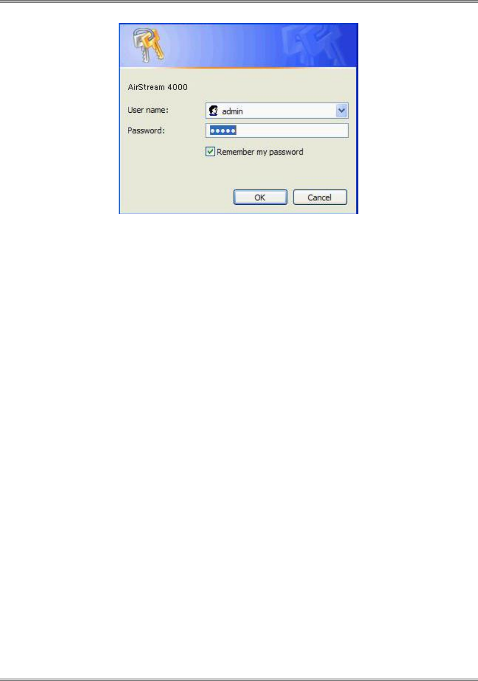
After IP layer connectivity is established between the Control Station and the CPE, the user may launch a Web browser
and specify http://192.168.0.1 in the address bar. A window will pop up requesting user name and password.
Input user name and password, and then click on the “OK” button. After a successful log on, the welcome page of web
management interface will appear.
CPE-O-R-WS User Manual
Runcom Technologies Ltd. 17
Figure 12: Logon Web Pages
4.2.2 Access CPE Device from WAN Segment
Service providers may access the CPE Web management interface remotely, by specifying the CPE wireless IP address
obtained after connecting to the service provider network.
As the wireless IP address is dynamically assigned by the service provider, the support technician may seek end user’s
help to find out the IP address of wireless interface for the CPE located in customer premise. The end user can retrieve
the wireless IP by following the instructions given in WiMAX CPE User Manual.
CPE-O-R-WS User Manual
18 Runcom Technologies Ltd.
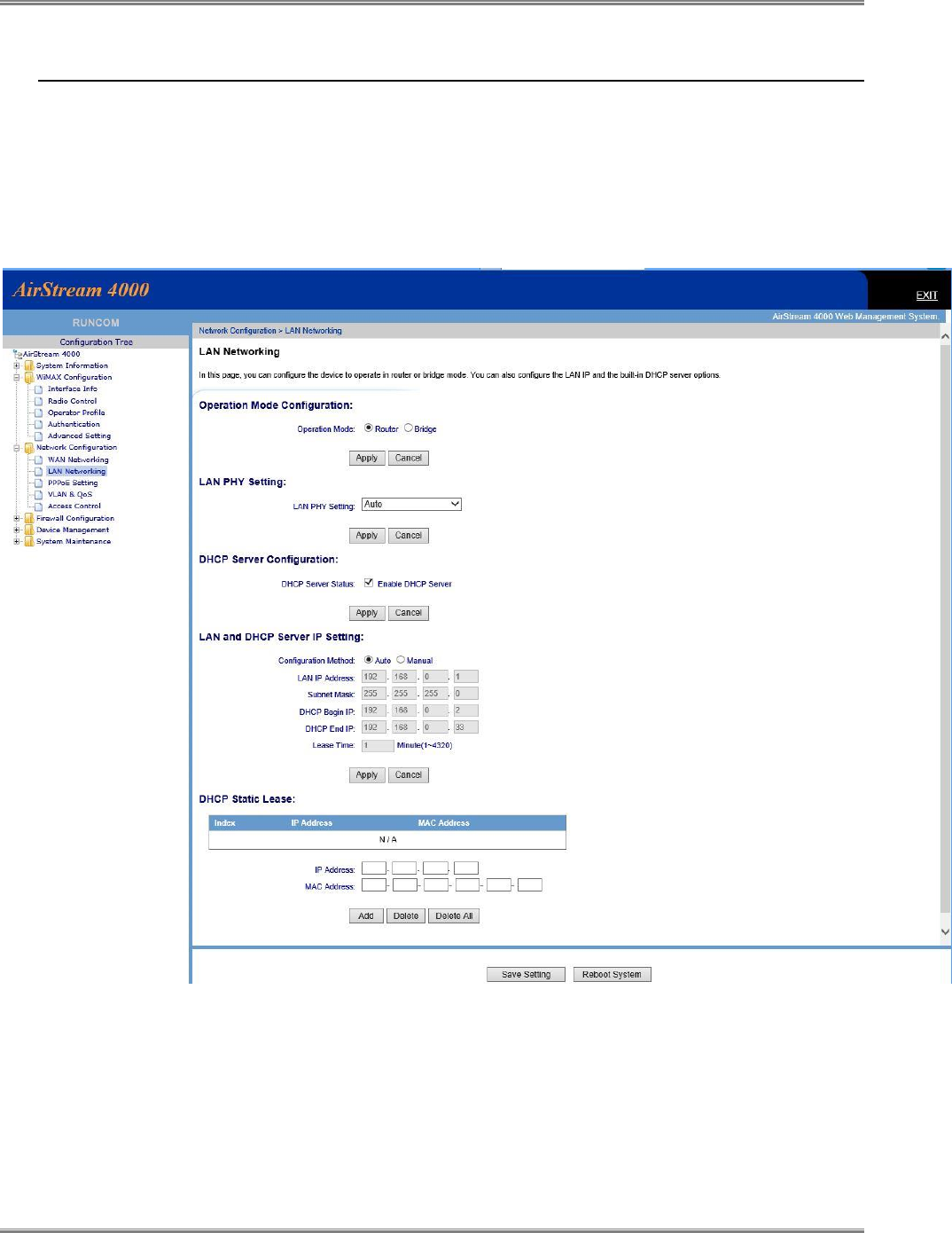
4.3 CPE LAN Side Network configuration
The CPE can act as “Router” or as “Bridge”. In router mode the CPE has DHCP function to allocate IP address to the
user devices, while in bridge mode the IP allocation is done in the network resources (such as MicroNOC).
Clarification: bridge mode is layer 3 bridge and not layer 2 bridge
To configure the LAN interface select in the menu “Network Configuration”, and “LAN Networking”
Figure 13: LAN Network Configuration
4.3.1 Router / Bridge selection
The selection between router and bridge operation mode is done on the “Operation Mode Configuration” and should be
followed by “apply” immediately.

CPE-O-R-WS User Manual
Runcom Technologies Ltd. 19
4.3.2 DHCP
If route mode selected, the CPE can be used as DHCP server by enabling it at “DHCP server configuration”
4.3.3 LAN IP settings
If router mode selected, the LAN IP address should be defined with the subnet mask.
If DHCP enabled, the start IP and end IP address should be defined. The DHCP IPs must be under the subnet range.
Other IPs which are not in the DHCP range, can be used by manually configuration of the devices behind CPE or by
DHCP static lease (configuring static IP for specific device recognized by MAC address).
Lease time define the time which the IP is reserved for a specific MAC identifier after connection loss. In case of CPE
power loss or reboot all reserved IPs are removed from the list.
CPE-O-R-WS User Manual
20 Runcom Technologies Ltd.
4.4 CPE WAN Side Network configuration
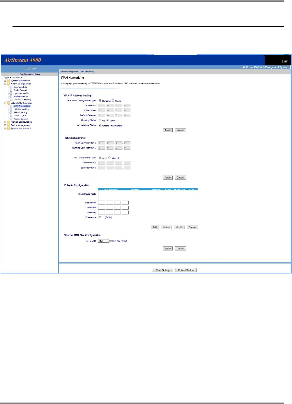
To configure the WAN (WiMAX) interface select in the menu “Network Configuration”, and “WAN Networking”
Figure 14: WAN Network Configuration
4.4.1 WAN interface enabling
There is an option to disable or enable the WAN (WiMAX) interface by ticking the field “enable this
interface”
4.4.2 WAN IP Address Settings
Two options available: Static IP address and Network DHCP IP address
Static IP Address – insert the IP address according to the network manager information. Default
gateway IP address is a must.
CPE-O-R-WS User Manual
Runcom Technologies Ltd. 21
Dynamic IP Address – by selecting this option the CPEA acquire IP address from the WiMAX
network DHCP server or from the xNOC static settings. If this option selected, the fields shows
the acquired IP address, Mask and default gateway.
4.4.3 DNS IP Address Settings
It is recommended to use Auto in this field. The xNOC is redirecting the request to the appropriate server
as defined in the xNOC.
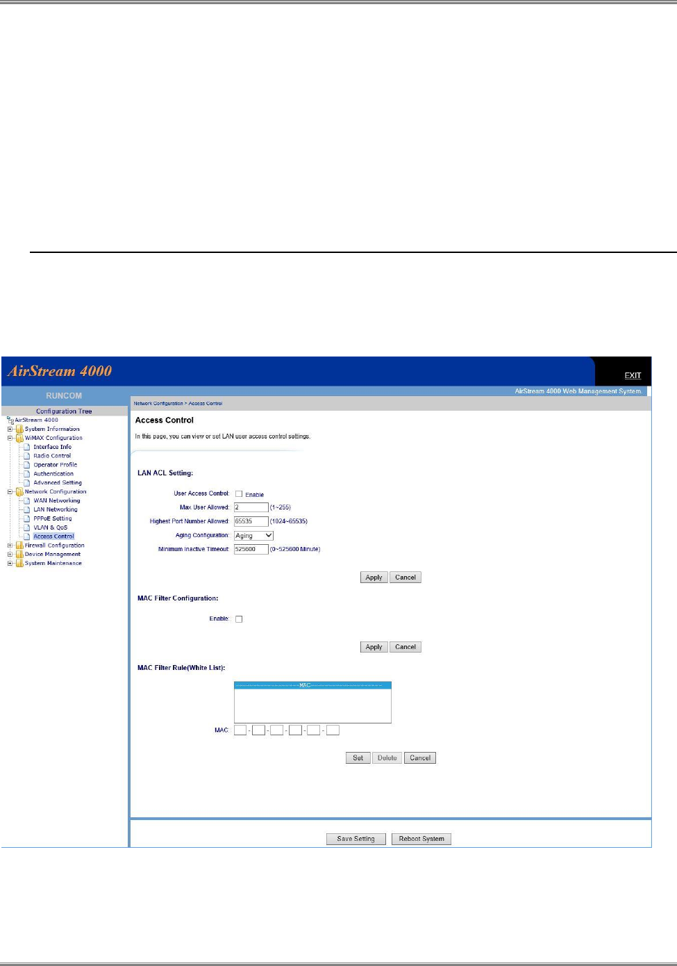
4.5 LAN access control
The CPE supports additional layer of access control, which help to prevent unappropriated use of the CPE.
If the CPE is operating as bridge mode, it is recommended to use access control of each CPE at the xNOC and
not at the CPE itself.
Figure 15: Access Control Configuration

CPE-O-R-WS User Manual
22 Runcom Technologies Ltd.
If router mode selected and the operator would like to control access use local control tick the field “user access
control”.
If “enable” selected the operator should define the allowed number of users behind CPE, and the
“inactive timeout”
MAC filtering is also available
CPE-O-R-WS User Manual
Runcom Technologies Ltd. 23
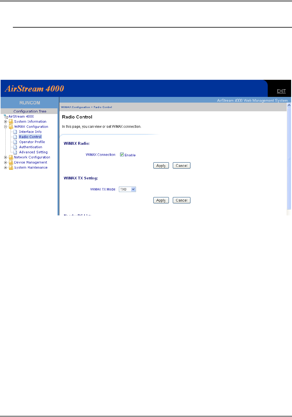
4.6 Radio Control
4.6.1 Radio Transmission Enable
The WAN interface is a wireless WiMAX radio interface. The CPE radio link must be enabled, by ticking
the WiMAX connection, to connect to the wireless network and connect the user behind CPE.
Figure 16: WiMAX Radio Control
4.6.2 Radio Signal Transmission
For TVWS CPEs the radio signal is transmitting only from Antenna interface 1. Therefor the WIMAX TX
Mode must be “TX0” and not other options.

CPE-O-R-WS User Manual
24 Runcom Technologies Ltd.
4.7 Operation Channels Frequency Control
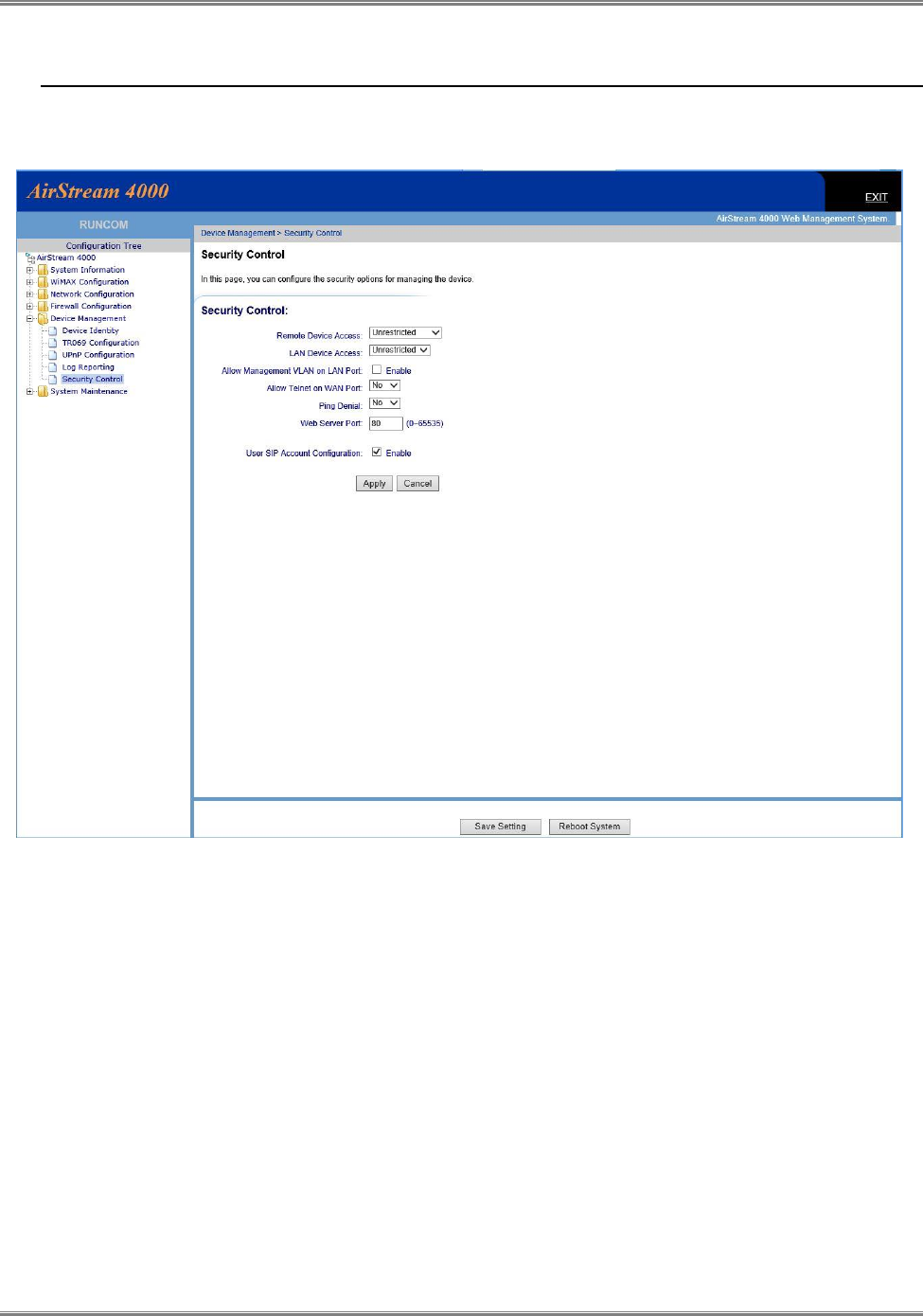
Figure 17: Operation Channels Frequency Control
4.7.1 Adding Allowed Channels
The list of allowed channel for the CPE installation location, which was downloaded from an authorized
web site, should be uploaded to the CPE manually or automatically by the AFAS.
At least one channel, which has the frequency of the local BTS site must be loaded manually.
Warning! – use discrete channels settings only!
Channel ID – Integer 0 to 99. The number is the local CPE ID number for the channels. The CPE
scan the air to locate authorized BTS from channel 0 to the highest channel and return to zero.
Frequency – The central frequency of the channel.
Bandwidth – 5000 Khz is the only option for USA.
Frame Duration – 5000us is the only option for WiMAX network.
After inserting the information push the “add” button.
CPE-O-R-WS User Manual
Runcom Technologies Ltd. 25
4.8 Controlling CPE access
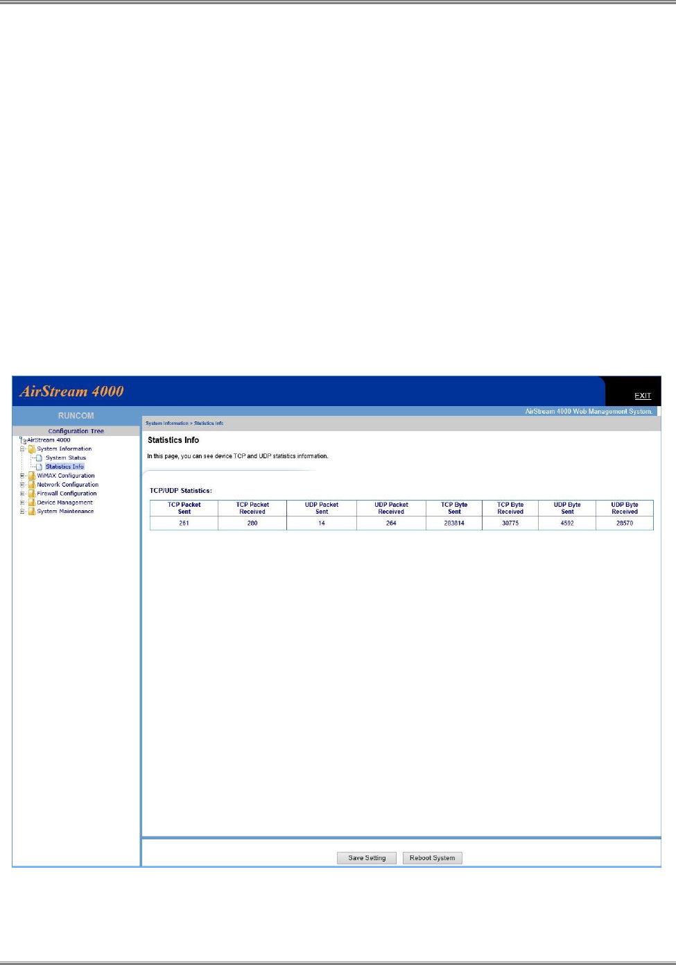
There are options to block, restrict or allowed access to the CPE device from LAN side and / or WAN side.
Figure 18: Device Access options

CPE-O-R-WS User Manual
26 Runcom Technologies Ltd.
4.9 Viewing CPE status Information
The CPE status shows the static configuration and information of the CPE device and live wireless connection status
information.
Figure 19: CPE Status Information
4.9.1 Running Information
The Running information shows the CPE user side configuration information and the system up time from
power on. The date and time of the day are valid only if updated from remote server.
4.9.2 WiMAX Information
The WiMAX information shows the following:
CPE-O-R-WS User Manual
Runcom Technologies Ltd. 27
Status – the air connection status. Searching – looking for valid WiMAX frame from base station,
DL Synchronization – BTS found and the CPE is performing network entry protocols, Operation
– the CPE is in service.
IP Address – if DHCP presented: CPE wait to get IP from the network resources. If data is
presented – it is the IP address, mask, gateway that the xNOC supported. If STATIC and data – it
is the static configuration at the CPE
4.9.3 LAN Information
Valid in router mode and shows the LAN configuration
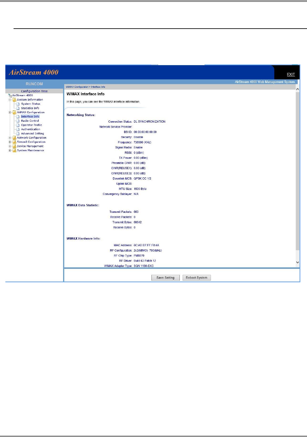
4.9.4 Traffic Statistic Information
This page shows the traffic which transferred over the WiMAX air interface.
Figure 20: Traffic Data Counters
CPE-O-R-WS User Manual
28 Runcom Technologies Ltd.
4.10 Viewing Wireless status and Information
The WiMAX status and information page includes important information which assist operator and installer to identify
proper installation and operation of CPE device
Figure 21: WiMAX Interface Status and Information
4.10.1 Networking Status
Connection Status: shows the air interface state status
BS ID – if not 00:00:00… shows the ID of the base station which the CPE is connected to
Frequency – shows the channel which is selected to connect to the BTS
RSSI – the radio signal strength that the CPE receive the BTS
Tx Power – the TX power which the BTS request from the CPE to transmit
CINR – the calculated signal to noise ratio.

CPE-O-R-WS User Manual
Runcom Technologies Ltd. 29
4.10.2 WiMAX Data Statistics
This information presents the traffic which is passing via the air interface
4.10.3 Hardware Information
Shows the air interface MAC addresses which the BTS and xNOC see during system entrée, authentication and
authorization processes.
CPE-O-R-WS User Manual
30 Runcom Technologies Ltd.
5 MAX Rx Signal Adjusting
5.1 RF Signal Adjusting
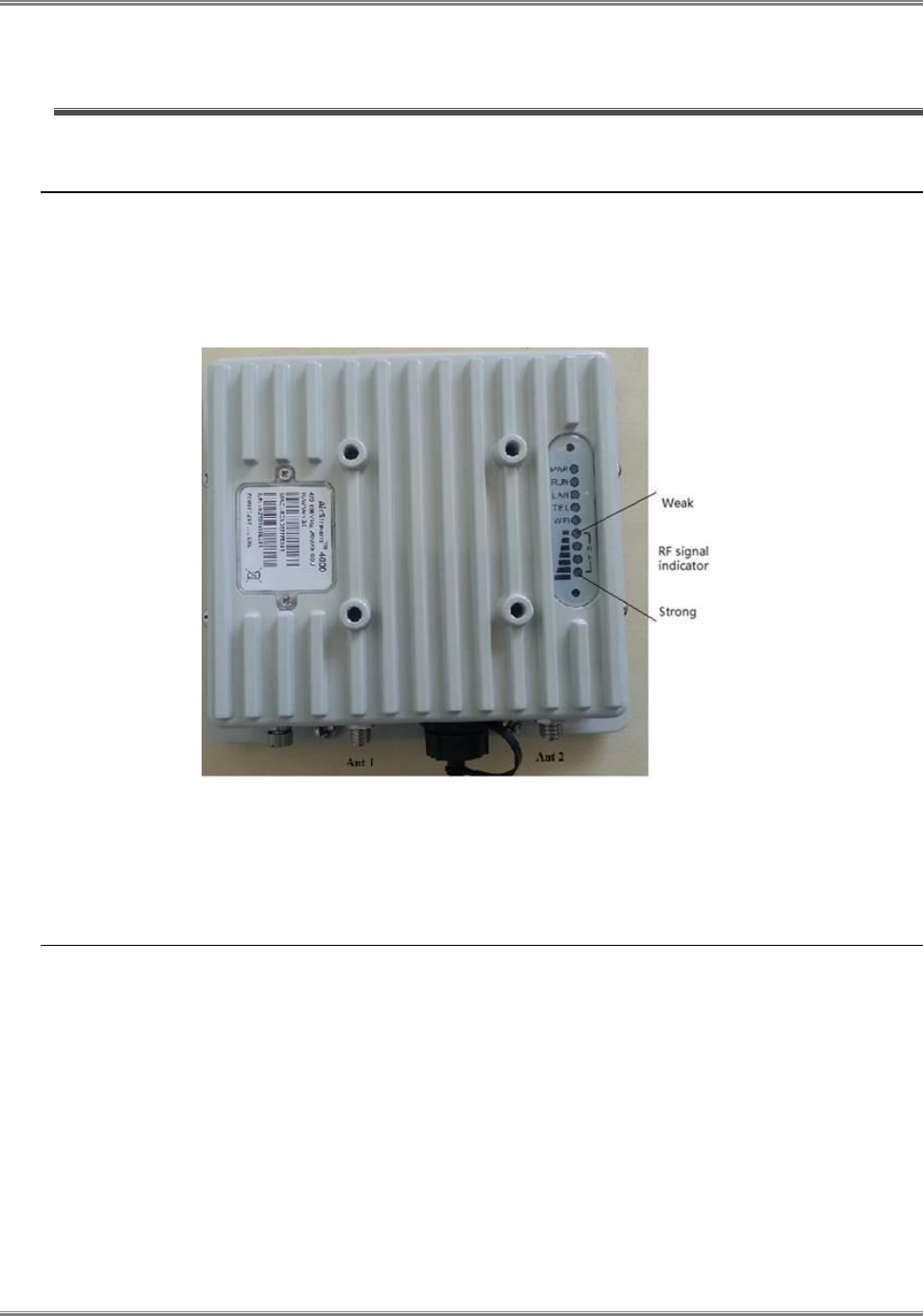
When the TVWS CPE ODU has installed, the direction of antenna’s azimuth and pitch angle needs to adjust for the best signal
strength, if the antenna is just pointing the base station the signal will be the best strength.
Thus, we can adjust the holder to change the direction and angle of the antenna while observing the RF LED of the ODU which
indicates the signal
Figure 22: Signal Indicators
5.2 Link Status
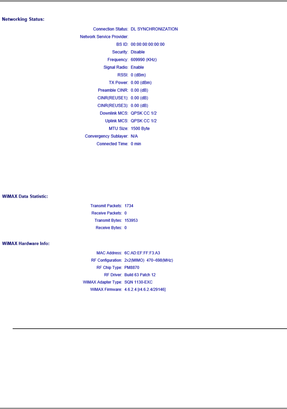
When clicking on the “Interface Info” link, the following WiMAX interface information is displayed.
5.2.1 Networking Status
Additional interface information such as RSSI, uplink or downlink throughput will be added in the coming software
release.
CPE-O-R-WS User Manual
Runcom Technologies Ltd. 31
5.2.2 WiMAX data statistics and Hardware information
The WiMAX data statistics shows the wireless data traffic amount and the hardware info displays the underlying
WiMAX chipset and driver information.
The configuration of WiMAX other parameters reference by following instructions given in WiMAX CPE User Manual.
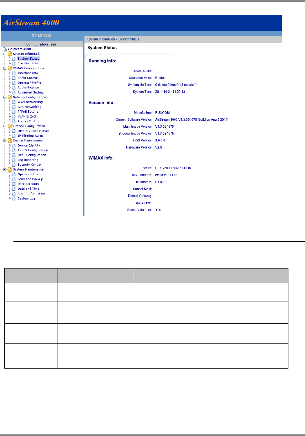
5.3 Welcome WEB Page
The following figure shows the Welcome page of web management interface of AirStream 4000 CPE which provides 1
LAN ports, 1 Phone line port.
And the CPE connected to the WiMAX base station successfully.
CPE-O-R-WS User Manual
32 Runcom Technologies Ltd.
5.4 LED Display
Table 7: Led Display
LED Indicator
Function
Description
PWR
Power Indicator
Green Color – Device is powered on
RUN
System Run Indicator
Fast Blinking – Device is rebooting
Slow Blinking – Device is in normal operation
LAN
LAN port status
Solid Green – LAN port is up
Blinking Green – LAN data activity in progress
RF (4 LEDs)
RF Signal Strength
4 level signal strengths indication by 4 green LEDs