Ryobi Ryi2011T Owner S Manual
2014-07-06
: Ryobi Ryobi-Ryi2011T-Owner-S-Manual ryobi-ryi2011t-owner-s-manual ryobi pdf
Open the PDF directly: View PDF ![]() .
.
Page Count: 72
Ce generator portable a été conçu et fabriqué conformément à
nos strictes normes de fiabilité, simplicité d’emploi et sécurité
d’utilisation. Correctement entretenu, cet outil vous donnera des
années de fonctionnement robuste et sans problème.
DANGER : Le non-respect des instructions fournies
dans ce manuel d’utilisation entraînera des BLESSURES
GRAVES, voire MORTELLES.
Merci de votre achat.
Su generator diseñado y fabricado de conformidad con nuestras
estrictas normas para brindar fiabilidad, facilidad de uso y
seguridad para el operador. Con el debido cuidado, le brindará
muchos años de sólido funcionamiento y sin problemas.
PELIGRO: El incumplimiento de las instrucciones en
este manual del operador puede CAUSARLE LA MUERTE O
LESIONARLE GRAVEMENTE.
Le agradecemos su compra.
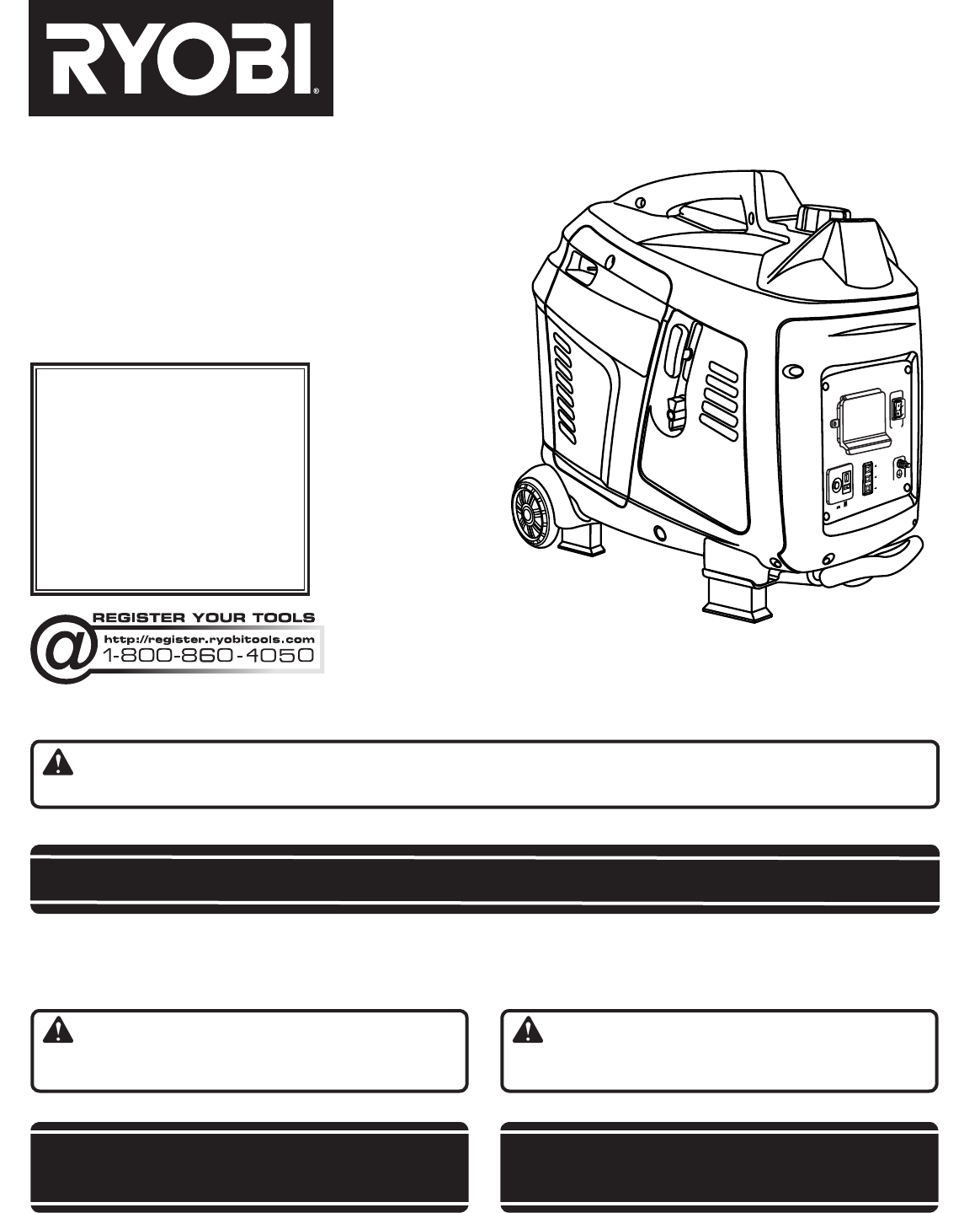
Your generator has been engineered and manufactured to our high standard for dependability, ease of operation, and op-
erator safety. When properly cared for, it will give you years of rugged, trouble-free performance.
DANGER: You WILL be KILLED or SERIOUSLY HURT if you do not follow the instructions in this operator’s
manual.
Thank you for your purchase.
OPERATOR’S MANUAL
MANUEL D’UTILISATION
MANUAL DEL OPERADOR
CONSERVER CE MANUEL POUR
FUTURE RÉFÉRENCE GUARDE ESTE MANUAL PARA
FUTURAS CONSULTAS
SAVE THIS MANUAL FOR FUTURE REFERENCE
DIGITAL INVERTER GENERATOR
GÉNÉRATEUR NUMÉRIQUE
D’INVERSEUR
GENERADOR DEL INVERSOR
DE DIGITACES
RYi2011T
To register your Ryobi
product, please visit:
http://register.ryobitools.com/
Pour enregistrer votre produit
de Ryobi, s’il vous plaît la visite:
http://register.ryobitools.com/
Para registrar su producto de
Ryobi, por favor visita:
http://register.ryobitools.com/
O
V
E
R
L
O
A
D
PO
W
E
R
L
O
W
O
I
L
G
R
O
U
N
D
O
F
F
O
N
A
U
T
O
I
D
L
E
:
12
V
5
A
S
U
RG
E
P
R
O
T
E
C
T
O
R
O
F
F
O
N
NEUTRAL FLOATING
FLOTTANTE NEUTRE / NEUTRAL DE FLOTACIÓN
ii
See this fold-out section for all of the figures referenced
in the operator’s manual.
Consulter l’encart à volets afin d’examiner toutes les
figures mentionnées dans le manuel d’utilisation.
Consulte esta sección desplegable para ver todas las
figuras a las que se hace referencia en el manual del
operador.
iii
O
V
E
R
L
O
A
D
PO
W
E
R
L
O
W
O
I
L
G
R
O
U
N
D
O
F
F
O
N
A
U
T
O
I
D
L
E
:
12
V
5
A
S
U
RG
E
P
R
O
T
E
C
T
O
R
O
F
F
O
N
O
V
E
R
L
O
A
D
PO
W
E
R
L
O
W
O
I
L
G
R
O
U
N
D
O
F
F
O
N
A
U
T
O
I
D
L
E
:
12
V
5
A
S
U
RG
E
P
R
O
T
E
C
T
O
R
O
F
F
O
N
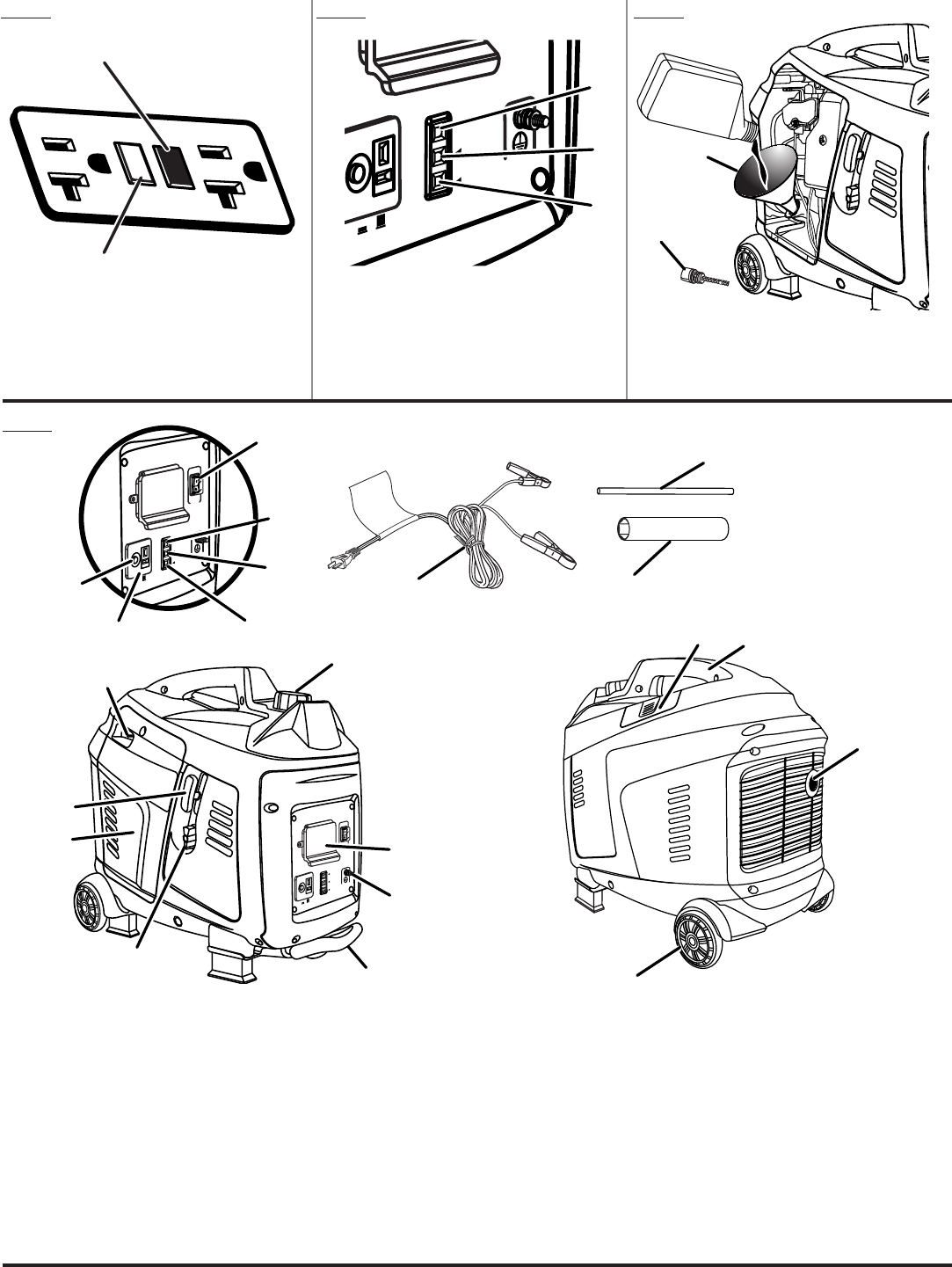
Fig. 2
A - On/Off switch (commutateur marche/arrêt, interruptor de encendido y
apagado)
B - Engine maintenance cover (couvercle pour l’entretien du moteur, cubierta
de mantenimiento del motor)
C - Recoil starter (lanceur à rappel, arrancador retráctil)
D - Choke lever (levier d’étrangleur, palanca del anegador)
E - Fuel cap (bouchon du réservoir bouchon du réservoir, tapa del tanque de
combustible)
F - 120 volt GFCI AC 20 amp receptacles (prises 120 V c.a. 20 A protégées
par le disjoncteur de fuite à la terre, 120 V de ca GFCI 20 A receptáculos)
G - Ground terminal (borne de terre, terminal de conexión a tierra)
H - Retractable handle (poignée rétractable, mango retráctil)
I - Battery charging cable (câble du charge pile, cable para cargar la batería)
J - Spark plug wrench (clé à bougie, llave para bujía)
K - 12 volt DC receptacle (prise de 12 V c.c, receptáculo de 12 V cc)
L - Low oil indicator (l’indicateur de bas niveau d’huile, luz de bajo nivel de
lubricante)
M
- Overload indicator (indicateur de surcharge, indicador de sobrecarga)
N - Power indicator (voyant d’alimentation, indicador de potencia)
O - Auto idle (mode de marche au ralenti automatique, ralentí automático)
P - Spark plug cover (couvercle de la bougie, cubierta de la bujía)
Q - Carry handle (poignée de transport, mango de acarreo)
R - Muffler with spark arrestor screen (silencieux avec écran pare-étincelles,
silenciador con pantalla parachispas)
S - Wheel (roulette, rueda)
T - DC circuit breaker (disjoncteur d.c., disyuntor de circuito de d.c)
U - Wrench handle (poignée de la clé, mango de la llave)
A
B
C
Fig. 3Fig. 1
A - Overload indicator (indicateur de surcharge,
indicador de sobrecarga)
B - Power indicator (voyant d’alimentation,
indicador de potencia)
C - Low oil indicator (l’indicateur de bas niveau
d’huile, luz de bajo nivel de lubricante)
I
N
K
T
M
L
O
S
J
U
PQ
R
O
V
E
R
L
O
A
D
PO
W
E
R
L
O
W
O
I
L
G
R
O
U
N
D
O
F
F
O
N
A
U
T
O
I
D
L
E
:
12
V
5
A
S
U
RG
E
P
R
O
T
E
C
T
O
R
O
F
F
O
N
C
B
DE
F
A
G
H
A - Test button (essayer le bouton, botón de
prueba)
B - Reset button (bouton de réarmement, botón
de reajuste)
B
A
O
V
E
R
L
O
A
D
PO
W
E
R
L
O
W
O
I
L
G
R
O
U
N
D
O
F
F
O
N
A
U
T
O
I
D
L
E
:
12
V
5
A
S
U
RG
E
P
R
O
T
E
C
T
O
R
O
F
F
O
N
A
Fig. 4
A - Oil cap/dipstick (bouchon/ jauge d’huile,
tapa de relleno de aceite/varilla medidora de
aceite)
B - Funnel (entonnoir, embudo)
B
iv
O
V
ER
L
O
A
D
P
O
W
ER
L
O
W
O
I
L
G
ROU
N
D
O
F
F
O
N
A
U
T
O
I
D
LE
:
1
2
V
5
A
S
UR
G
E
P
R
OT
EC
T
OR
O
F
F
O
N
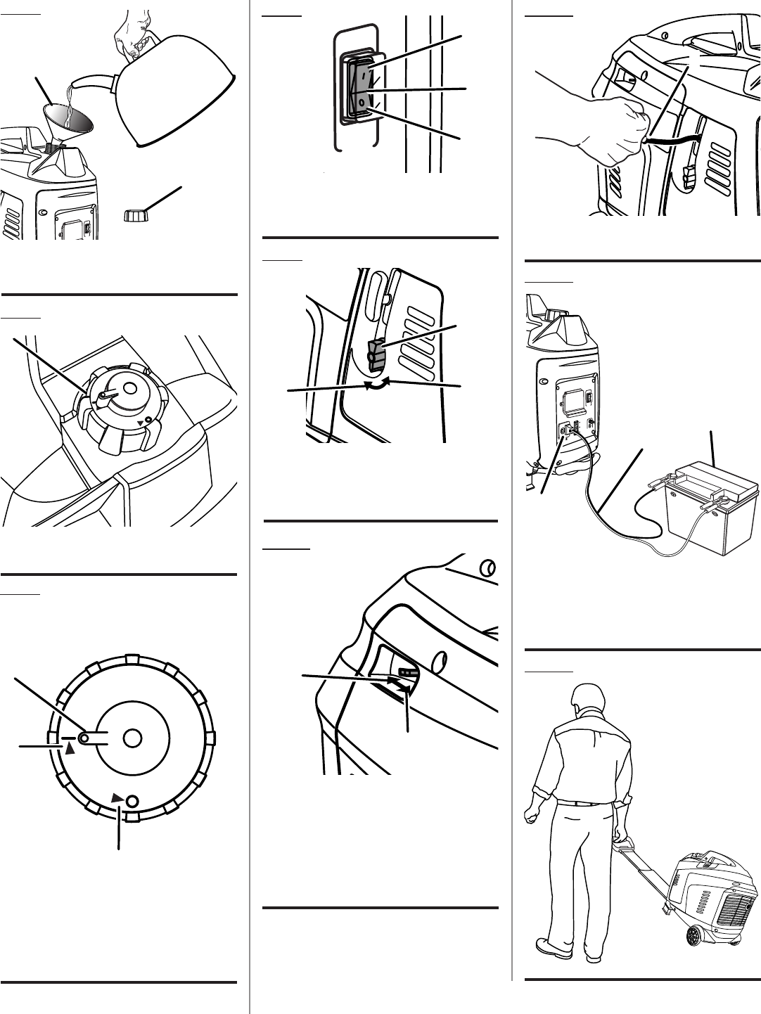
Fig. 9
Fig. 11Fig. 8
A - Recoil starter (lanceur à rappel, arrancador
retráctil)
Fig. 10
A - On/Off switch (commutateur marche/arrêt,
interruptor de encendido y apagado)
B - Off (arret, apagado)
C - On (marche, encendido)
A - Auto idle (mode de marche au ralenti
automatique, ralentí automático)
B - Off (arret, apagado)
C - On (marche, encendido)
A - Move choke lever right to start (tirer droite
le levier d’étranglement pour démarrer,
desplace derecha de la palanca del anegador
para arrancar)
B - Move choke lever left to run (pousser gauche
le levier d’étranglement pour la marche,
desplace izquierda la palanca del anegador
para poner en marcha)
O
V
E
R
L
O
A
D
PO
W
E
R
L
O
W
O
I
L
G
R
O
U
N
D
O
F
F
O
N
A
U
T
O
I
D
L
E
:
12
V
5
A
S
U
RG
E
P
R
O
T
E
C
T
O
R
O
F
F
O
N
O
N
OF
F
O
V
E
R
L
O
A
D
PO
W
E
R
L
O
W
O
I
L
G
R
O
U
N
D
O
F
F
O
N
A
U
T
O
I
D
L
E
:
12
V
5
A
S
U
RG
E
P
R
O
T
E
C
T
O
R
O
F
F
O
N
O
V
E
R
L
O
A
D
PO
W
E
R
L
O
W
O
I
L
G
R
O
U
N
D
O
F
F
O
N
A
U
T
O
I
D
L
E
:
12
V
5
A
S
U
RG
E
P
R
O
T
E
C
T
O
R
O
F
F
O
N
A
A
B
A
B
B
C
C
O
V
E
R
L
OA
D
PO
W
E
R
L
O
W
O
I
L
G
ROU
N
D
O
F
F
O
N
A
U
T
O
I
D
L
E
:
12
V
5
A
S
U
RG
E
P
R
O
T
E
C
T
O
R
O
F
F
O
N
A
B
Fig. 5
A - Funnel (entonnoir, embudo)
B - Fuel cap (bouchon du réservoir bouchon du
réservoir, tapa del tanque de combustible)
A
Fig. 6
Fig. 7
A - Fuel cap (bouchon du réservoir, tapa del
tanque de combustible)
A - Fuel cap lever (levier du bouchon de
carburant, palanca de la tapa de combustible)
B - Open/Run position (position ouverte /
marche, posición abierto/marcha)
C - Closed/Storage position (position
fermé / rangement, posición cerrado/
almacenamiento)
O
N
O
F
F
Top View
Vue de haut / Vista superior
A
B
C
O
F
F
O
N
A
Fig. 13
O
V
E
R
L
O
A
D
PO
W
E
R
L
O
W
O
I
L
G
ROU
N
D
O
F
F
O
N
A
U
T
O
I
D
L
E
:
12
V
5
A
S
U
RG
E
P
R
OT
E
CT
O
R
O
F
F
O
N
Fig. 12
A - 12 volt DC receptacle (prise de 12 V c.c,
receptáculo de 12 V cc)
B - Battery charging cable (câble du charge pile,
cable para cargar la batería)
C - Battery (piles, batería)
A
B
C
v
O
V
E
R
L
OA
D
PO
W
E
R
L
O
W
O
I
L
G
R
O
U
N
D
O
FF
O
N
A
U
T
O
I
D
L
E
:
12
V
5
A
S
U
RG
E
P
R
OT
E
CT
O
R
O
F
F
O
N
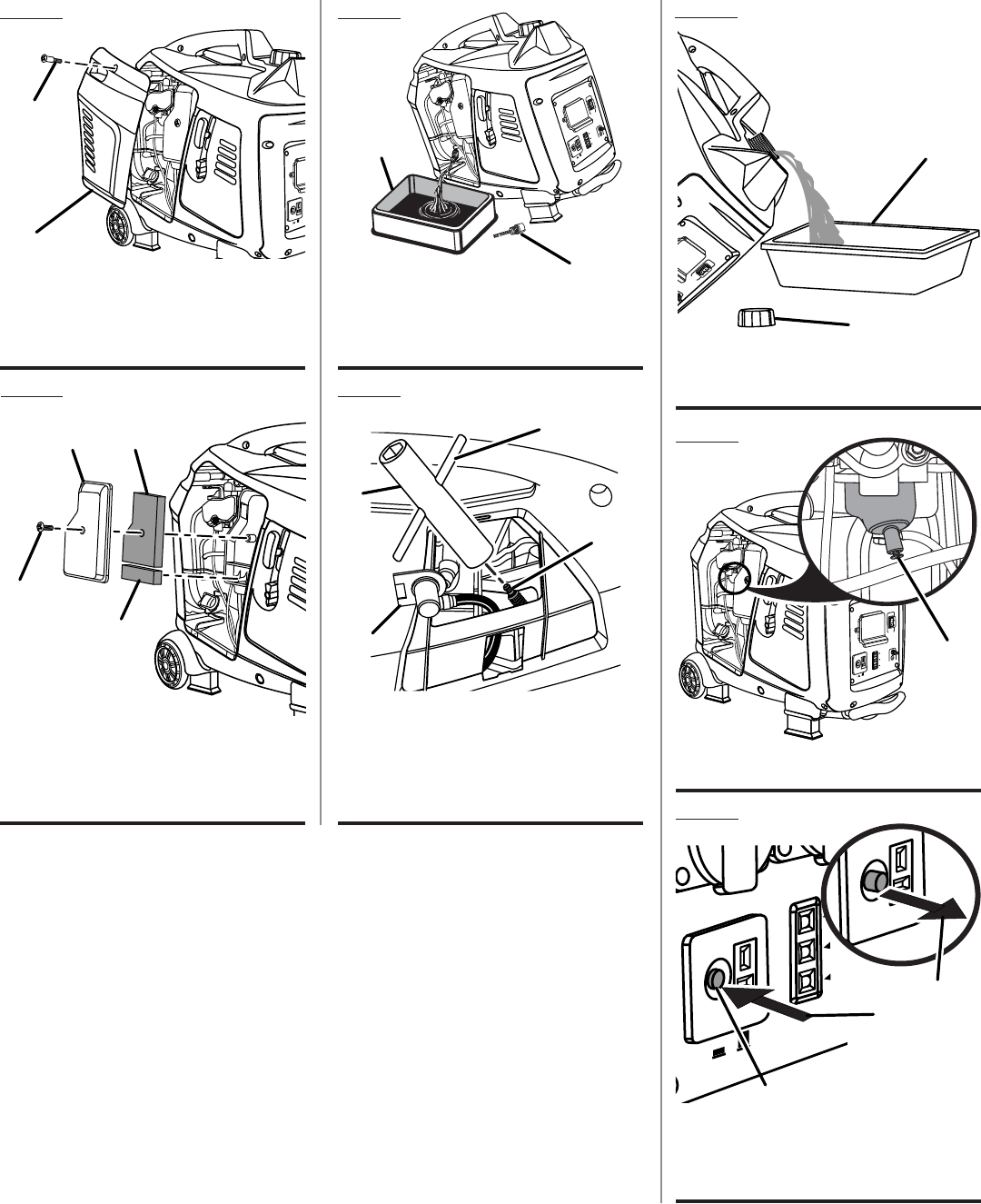
Fig. 18
Fig. 19
A - Fuel cap (bouchon du réservoir bouchon du
réservoir, tapa del tanque de combustible)
B - Container (conteneur, recipiente)
A - Carburetor drain screw (vis de vidange du
carburateur, tornillo de drenaje del caburador)
A
A
B
O
F
F
O
N
:
12
V
5
A
A
U
T
O
I
D
L
E
AC
1
2
0V
O
V
E
R
L
OA
D
P
O
W
E
R
L
OW
O
I
L
O
F
F
S
U
R
GE
P
R
O
T
EC
T
O
R
O
N
O
F
F
O
N
:
12
V
5
A
A
U
T
O
I
D
L
E
AC
1
2
0V
O
V
E
R
L
OA
D
P
O
W
E
R
L
OW
O
I
L
O
F
F
S
U
R
GE
P
R
O
T
EC
T
O
R
O
N
Fig. 20
A - DC circuit breaker (disjoncteur d.c., disyuntor
de circuito de d.c)
B - Off (arret, apagado)
C - On (marche, encendido)
CB
A
O
V
E
R
L
O
A
D
PO
W
E
R
L
O
W
O
I
L
G
R
O
U
N
D
O
FF
O
N
A
U
TO
I
D
L
E
:
12
V
5
A
S
U
RG
E
P
R
O
T
E
C
T
OR
O
F
F
O
N
Fig. 17
A - Spark plug cap (capuchon de bougie, tapa de
la bujía)
B - Spark plug (bougie, bujía)
C - Spark plug wrench (clé à bougie,
D - Wrench handle (poignée de la clé, mango de
la llave)
A
B
C
D
Fig. 16
A - Oil cap/dipstick (bouchon/ jauge d’huile,
tapa de relleno de aceite/varilla medidora de
aceite)
B - Container (conteneur, recipiente)
O
V
E
R
L
OA
D
PO
W
ER
L
O
W
O
I
L
G
R
O
U
N
D
O
FF
O
N
A
U
T
O
ID
L
E
:
12
V
5
A
S
U
R
G
E
P
R
O
T
E
CT
O
R
O
F
F
O
N
B
A
Fig. 15
O
V
E
R
L
O
A
D
PO
W
E
R
L
O
W
O
I
L
G
R
O
U
N
D
O
F
F
O
N
A
U
T
O
I
D
L
E
:
12
V
5
A
S
U
RG
E
P
R
O
T
E
C
T
O
R
O
F
F
O
N
A - Air filter cover (couvercle du filtre à air, tapa
del filtro de aire)
B - Screw (vis, tornillo)
C - Filter element (élément du filtre, elemento de
filtro)
A
B
C
C
O
V
E
R
L
O
A
D
PO
W
E
R
L
O
W
O
I
L
G
R
O
U
N
D
O
F
F
O
N
A
U
TO
I
D
L
E
:
12
V
5
A
S
U
RGE
P
R
O
T
E
C
T
O
R
O
F
F
O
N
Fig. 14
A - Engine maintenance cover (couvercle
pour l’entretien du moteur, cubierta de
mantenimiento del motor)
B - Screw (vis, tornillo)
A
B
2 — English
TABLE OF CONTENTS
INTRODUCTION
Introduction ......................................................................................................................................................................2
Important Safety Instructions ........................................................................................................................................3-4
Specific Safety Rules ........................................................................................................................................................ 4
Symbols ......................................................................................................................................................................... 5-7
Electrical ........................................................................................................................................................................7-9
Features ...................................................................................................................................................................... 9-10
Assembly ........................................................................................................................................................................ 11
Operation ................................................................................................................................................................... 12-14
Maintenance ..............................................................................................................................................................14-16
Troubleshooting .............................................................................................................................................................. 17
Warranty ....................................................................................................................................................................18-22
Parts Ordering / Service ....................................................................................................................................Back Page
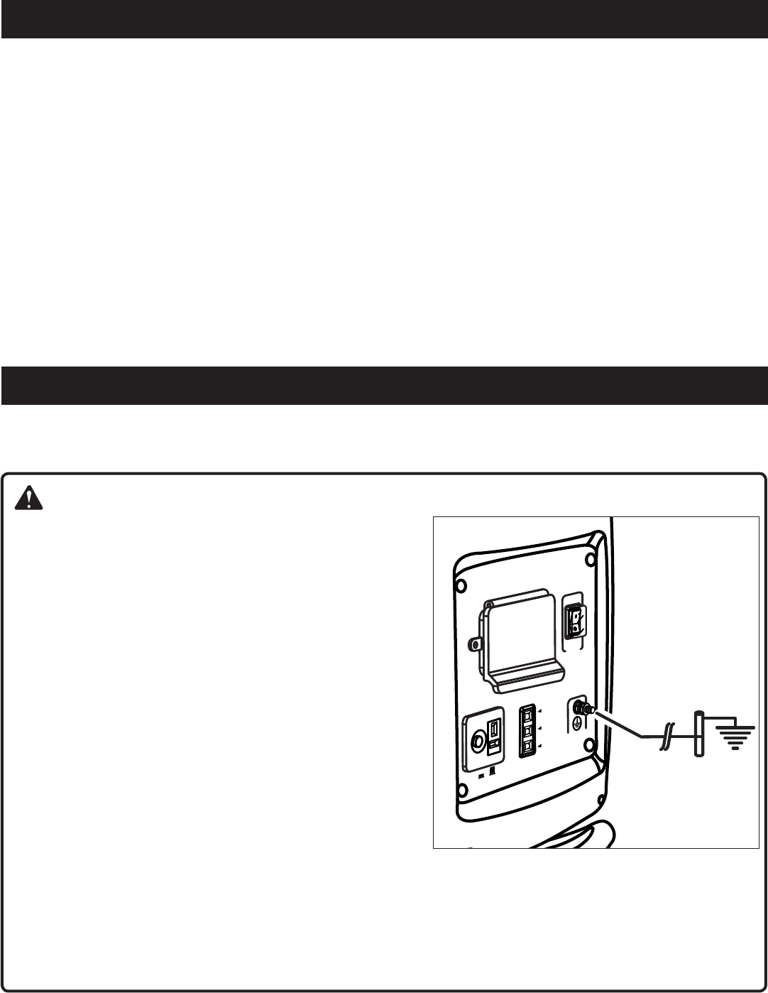
DANGER:
GROUNDING THE GENERATOR
To reduce the risk of shock or electrocution, generator must be
properly grounded. The nut and ground terminal on the frame must
always be used to connect the generator to a suitable ground
source. The ground path should be made with #8 size wire. Con-
nect the terminal of the ground wire between the lock washer and
the nut, and tighten the nut fully. Connect the other end of the
wire securely to a suitable ground source.
The National Electric Code contains several practical ways in
which to establish a good ground source. If a steel or iron rod is
used, it should be at least 5/8 in. diameter, and if a nonferrous
rod is used, it should be at least 1/2 in. diameter and be listed as
material for grounding. Drive the rod or pipe to a depth of 8 ft. If
a rock bottom is encountered less than 4 ft. down, bury the rod
or pipe in a trench.
All electrical tools and appliances operated from this generator
must be properly grounded by use of a third wire or be “Double
Insulated.”
It is recommended to:
1. Use electrical devices with 3-prong grounded plugs.
2. Use an extension cord with a 3-pole receptacle and a 3-prong plug at opposite ends to ensure continuity of the
ground protection from the generator to the appliance.
Check and adhere to all applicable federal, state, and local regulations relating to grounding specifications. Consult a
qualified electrician or service personnel if the grounding instructions are not completely understood or if in doubt as
to whether the generator is properly grounded.
This product has many features for making its use more pleasant and enjoyable. Safety, performance, and dependability
have been given top priority in the design of this product, making it easy to maintain and operate.
O
V
E
R
L
O
A
D
PO
W
E
R
L
O
W
O
I
L
G
R
O
U
N
D
O
F
F
O
N
A
U
T
O
I
D
L
E
:
12
V
5
A
S
U
RG
E
P
R
O
T
E
C
T
O
R
O
F
F
O
N
3 — English
IMPORTANT SAFETY INSTRUCTIONS
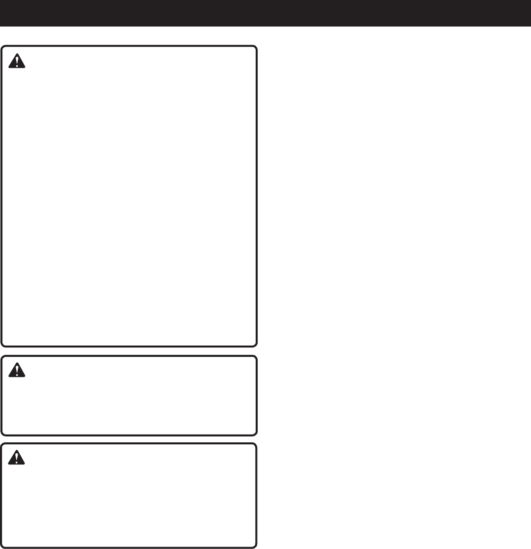
DANGER:
Carbon Monoxide. Using a generator indoors CAN KILL
YOU IN MINUTES.
Generator exhaust contains high levels of carbon
monoxide (CO), a poisonous gas you cannot see or smell.
If you can smell the generator exhaust, you are breathing
CO. But even if you cannot smell the exhaust, you could
be breathing CO.
Never use a generator inside homes, garages,
crawlspaces, or other partly enclosed areas. Deadly
levels of carbon monoxide can build up in these
areas. Using a fan or opening windows and doors
does NOT supply enough fresh air.
ONLY use a generator outdoors and far away from
open windows, doors, and vents. These openings
can pull in generator exhaust.
Even when you use a generator correctly, CO may
leak into the home. ALWAYS use a battery-powered or
battery-backup CO alarm in the home.
If you start to feel sick, dizzy, or weak after the generator
has been running, move to fresh air RIGHT AWAY. See
a doctor. You could have carbon monoxide poisoning.
WARNING:
Read and understand all instructions. Failure to follow
all instructions listed below may result in electrocution,
fire, and/or carbon monoxide poisoning, which will cause
death or serious injury.
WARNING:
National Electric Code requires generator to be grounded
to an approved earth ground. Before using the ground
terminal, consult a qualified electrician, electrical
inspector, or local agency having jurisdiction for local
codes or ordinances that apply to the intended use of
the generator.
SAVE THESE INSTRUCTIONS
This manual contains important instructions for this product
that should be followed during installation and maintenance
of the generator and batteries.
Do not connect to a building’s electrical system unless
the generator and transfer switch have been properly
installed and the electrical output has been verified by a
qualified electrician.
Do not allow children or untrained individuals to use this
unit.
Never start or run the engine inside a closed or partially
enclosed area. Breathing exhaust fumes will kill you.
Always wear eye protection with side shields marked to
comply with ANSI Z87.1 as well as hearing protection
when operating this equipment.
Keep all bystanders, children, and pets at least 10 feet
away.
Wear sturdy and dry shoes or boots. Do not operate while
barefoot.
Do not operate generator when you are tired or under the
influence of drugs, alcohol, or medication.
Keep all parts of your body away from any moving parts
and all hot surfaces of the unit.
Do not touch bare wire or receptacles.
Do not use generator with electrical cords which are worn,
frayed, bare, or otherwise damaged.
Before storing the unit for an extended period of time
allow the engine to cool and drain fuel from the unit.
Do not operate or store the generator in rain, snow, or
wet weather.
Store the generator in a well-ventilated area with the fuel
tank empty. Fuel should not be stored near the generator.
Empty fuel tank, close fuel valve, and restrain the unit
from moving before transporting in a vehicle.
Allow engine to cool for five minutes before refueling.
To reduce the risk of fire and burn injury, handle fuel with
care. It is highly flammable.
Do not smoke while handling fuel.
Store fuel in a container approved for gasoline.
Position the unit on level ground, stop engine, and allow
to cool before refueling.
Loosen fuel cap slowly to release pressure and to keep
fuel from escaping around the cap.
Tighten the fuel cap securely after refueling.
Wipe spilled fuel from the unit.
Never attempt to burn off spilled fuel under any circum-
stances.
Generators vibrate in normal use. During and after the
use of the generator, inspect the generator as well as
extension cords and power supply cords connected to
it for damage resulting from vibration. Have damaged
items repaired or replaced as necessary. Do not use plugs
or cords that show signs of damage such as broken or
cracked insulation or damaged blades.
For power outages, permanently installed stationary gen-
erators are better suited for providing back-up power to
the home. Even a properly connected portable generator
can become overloaded. This may result in overheating
or stressing the generator components, possibly leading
to generator failure.

4 — English
IMPORTANT SAFETY INSTRUCTIONS
SPECIFIC SAFETY RULES
Use only authorized replacement parts and accessories
and follow instructions in the Maintenance section of this
manual. Use of unauthorized parts or failure to follow
maintenance instructions may create a risk of shock or
injury.
Maintain the unit per maintenance instructions in this
Operator’s Manual.
Inspect the unit before each use for loose fasteners, fuel
leaks, etc. Replace damaged parts.
WARNING:
When this generator is used to supply a building
wiring system: generator must be installed by a
qualified electrician and connected to a transfer switch
as a separately derived system in accordance with
NFPA 70, National Electrical Code. The generator shall
be connected through a transfer switch that switches
all conductors other than the equipment grounding
conductor. The frame of the generator shall be connected
to an approved grounding electrode. Failure to isolate the
generator from power utility can result in death or injury
to electric utility workers.
Do not use this generator to provide power for emergency
medical equipment or life support devices.
Exhaust contains poisonous carbon monoxide, a color-
less, odorless gas. Breathing exhaust can cause loss
of consciousness and can lead to death. If running in a
confined or partially-enclosed area, the air may contain
a dangerous amount of carbon monoxide. To keep ex-
haust fumes from building up, always provide adequate
ventilation.
Always use a battery-powered carbon monoxide detec-
tor when running the generator. If you begin to feel sick,
dizzy, or weak while using the generator, shut it off and
get to fresh air immediately. See a doctor. You may have
carbon monoxide poisoning.
Place the generator on a flat, stable surface with a slope
of no more than 4°.
Operate outdoors in a well-ventilated, well-lit area isolated
from working areas to avoid noise interference.
Operating the generator in wet conditions could result in
electrocution. Keep the unit dry.
Keep the generator a minimum of 3 feet away from all
types of combustible material.
Do not operate generator near hazardous material.
Do not operate generator at a gas or natural gas filling
station.
Do not touch the muffler or cylinder during or immediately
after use; they are HOT and will cause burn injury.
This generator has a neutral floating condition. This means
the neutral conductor is not electrically connected to the
frame of the machine.
Do not allow the generator’s gas tank to overflow when
filling. Fill to 1 in. below the top neck of the gasoline tank
to allow for fuel expansion.
Do not smoke when filling the generator with gasoline.
Shut down the engine and allow to cool completely before
adding gasoline or lubricant to the generator.
Do not remove the oil dipstick or the fuel tank cap when
the engine is running.
Pay close attention to all safety labels located on the
generator.
Keep children a minimum of 10 feet away from the gen-
erator at all times.
The unit operates best in temperatures between 23°F and
104°F with a relative humidity of 90% or less.
Specific modifications for high-altitude performance are
needed if the generator will always be operated at alti-
tudes above 5,000 feet. Contact your nearest authorized
service center for more information and to have these
modifications performed.
Operating voltage and frequency requirement of all
electronic equipment should be checked prior to plug-
ging them into this generator. Damage may result if the
equipment is not designed to operate within a +/- 10%
voltage variation, and +/- 3 hz frequency variation from
the generator name plate ratings.
Save these instructions. Refer to them frequently and use
them to instruct others who may use this product. If you
loan someone this product, loan them these instructions
also.
5 — English
SYMBOLS
Some of the following symbols may be used on this product. Please study them and learn their meaning. Proper
interpretation of these symbols will allow you to operate the product better and safer.
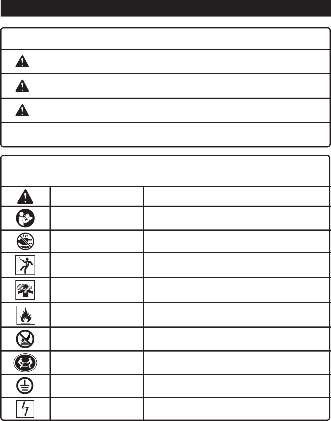
SYMBOL NAME DESIGNATION/EXPLANATION
Safety Alert Indicates a potential personal injury hazard.
Read Operator’s Manual To reduce the risk of injury, user must read and understand
operator’s manual before using this product.
Wet Conditions Alert Do not expose to rain or use in damp locations.
Electric Shock Failure to use in dry conditions and to observe safe practices can
result in electric shock.
Toxic Fumes
Running generator gives off carbon monoxide, an odorless, color-
less, poison gas. Breathing carbon monoxide can cause nausea,
fainting, or death.
Fire/Explosion Fuel and its vapors are extremely flammable and explosive. Fire
or explosion can cause severe burns or death.
Hot Surface To reduce the risk of injury or damage, avoid contact with any hot
surface.
Lifting Hazard To reduce the risk of serious injury, avoid attempting to lift the
generator alone.
Ground Consult with local electrician to determine grounding requirements
before operation.
Electrocution Failure to properly ground generator can result in electrocution,
especially if the generator is equipped with a wheel kit.
The following signal words and meanings are intended to explain the levels of risk associated with this product.
SYMBOL SIGNAL MEANING
DANGER: Indicates an imminently hazardous situation, which, if not avoided, will result
in death or serious injury.
WARNING: Indicates a potentially hazardous situation, which, if not avoided, could result
in death or serious injury.
CAUTION: Indicates a potentially hazardous situation, which, if not avoided, may result in
minor or moderate injury.
CAUTION: (Without Safety Alert Symbol) Indicates a situation that may result in property
damage.
6 — English
SYMBOLS
Some of the following symbols may be used on this product. Please study them and learn their meaning. Proper
interpretation of these symbols will allow you to operate the product better and safer.
SYMBOL NAME DESIGNATION/EXPLANATION
V Volts Voltage
A Amperes Current
Hz Hertz Frequency (cycles per second)
W Watt Power
hrs Hours Time
gal Gallon Volume
qt Quart Volume
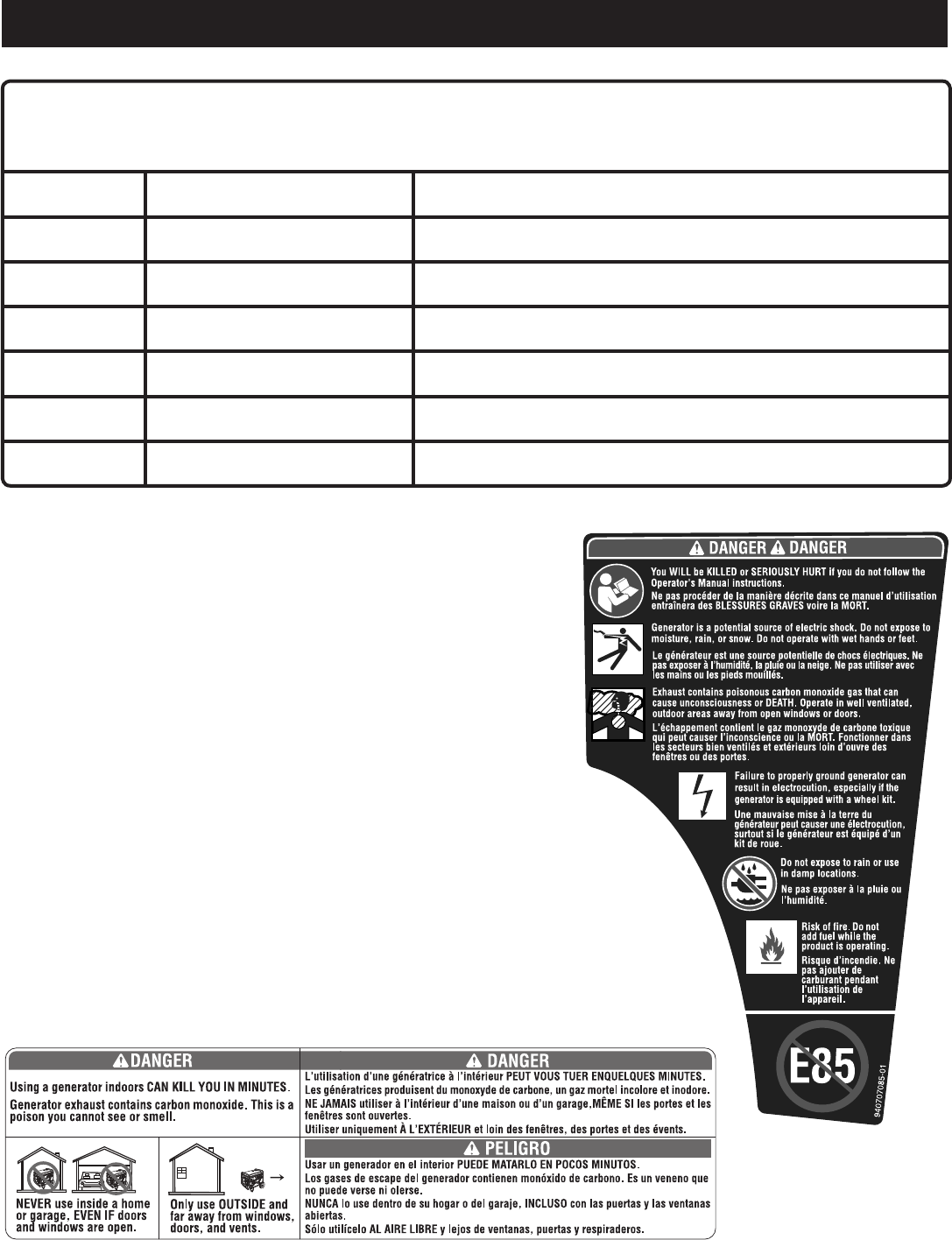
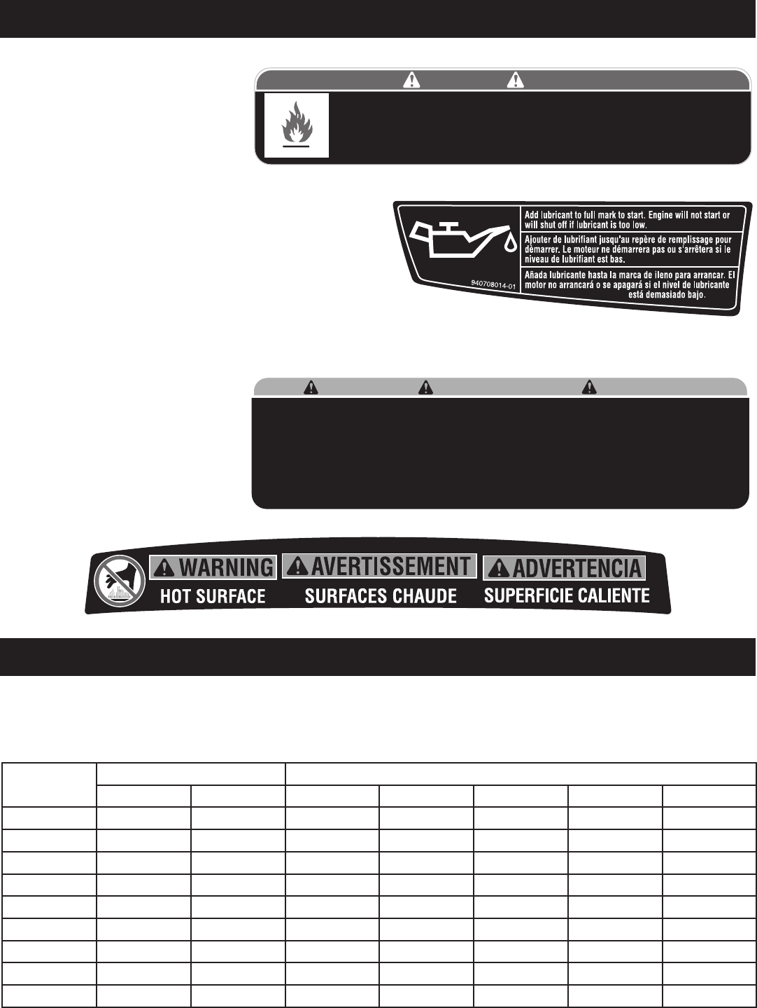
SAFETY LABELS
The information below can be found on the generator. For your safety,
please study and understand all of the labels before starting the generator.
If any of the labels come off the unit or become hard to read, contact an
authorized service center for replacement.
You WILL be KILLED or SERIOUSLY HURT if you do not follow the
Operator’s Manual instructions.
Risk of Fire. Do not add fuel while the product is operating.
Generator is a potential source of electric shock. Do not expose to
moisture, rain, or snow. Do not operate with wet hands or feet.
Exhaust contains poisonous carbon monoxide gas that can cause
unconsciousness or DEATH. Operate in well-ventilated, outdoor areas away
from open windows or doors.
Failure to properly ground generator can result in electrocution, especially if the
generator is equipped with a wheel kit.
Do not expose to rain or use in damp locations.
Using a generator indoors CAN KILL YOU IN MINUTES. Generator exhaust contains
carbon monoxide. This is a poison you cannot see or smell.
NEVER use inside a home or garage, EVEN IF doors and windows are open.
Only use OUTSIDE and far away from windows, doors, and vents.
Do not use E85 fuel.
7 — English
SYMBOLS
FUEL WARNING
No smoking when filling with gasoline.
Do not overfill. Full level is 1 in. below
the top of the fuel neck. Stop the en-
gine for five minutes before refueling to
avoid the heat from the muffler igniting
fuel vapors.
ENGINE LUBRICANT WARNING
You must add lubricant before first operating the generator. The
oil reservoir capacity is 0.42 qt. Always check the lubricant level
before each operation. The lubricant level should always register
between the hatched areas on the dipstick. The unit is equipped
with a sensor which will automatically shut off the engine if the
lubricant level falls below a safe limit.
GROUNDING WARNING
National Electric Code requires generator to be grounded to an approved earth ground.
HOT SURFACE WARNING
Do not touch the muffler or aluminum
cylinder of the engine. They are very HOT
and will cause severe burns. Don’t put
any flammable or combustible materials
in the direct path of the exhaust.
Product does not include ground rod or copper wire. National Electric Code requires generator to be
properly grounded to an approved earth ground. Call an electrician for local grounding requirements.
Le produit ne comprend pas de piquet de terre ou de fil en cuivre. Le code electrique americain (National
Electric Code) requiert un générateur pour une bonne mise à la terre approuvée. Appeler un électricien
pour connaître les exigences locales de mise à la terre.
El producto no incluye el alambre de cobre ni la barra de conexión a tierra. Los Reglamentos Nacionales
de Electricidad exigen que el generador esté debidamente conectado a una tierra aprobada.
Comuniquese con un electrista para todo lo relacionado con los requistos de conexión a tierra.
WARNING ADVERTENCIA
AVERTISSEMENT
940513008-02
Risk of Fire. Check for any fuel overflow or leaking. Stop the engine before refueling.
DANGER PELIGRO
Risque d’incendie. Vérifier l'absence de débordement ou de fuite de carburant.
Arrêter le moteur avant de fair le plein.
Riesgo de incendio. Revise si hay algún derrame o fuga de combustible. Apague el
motor antes de poner combustible. 940974007-03
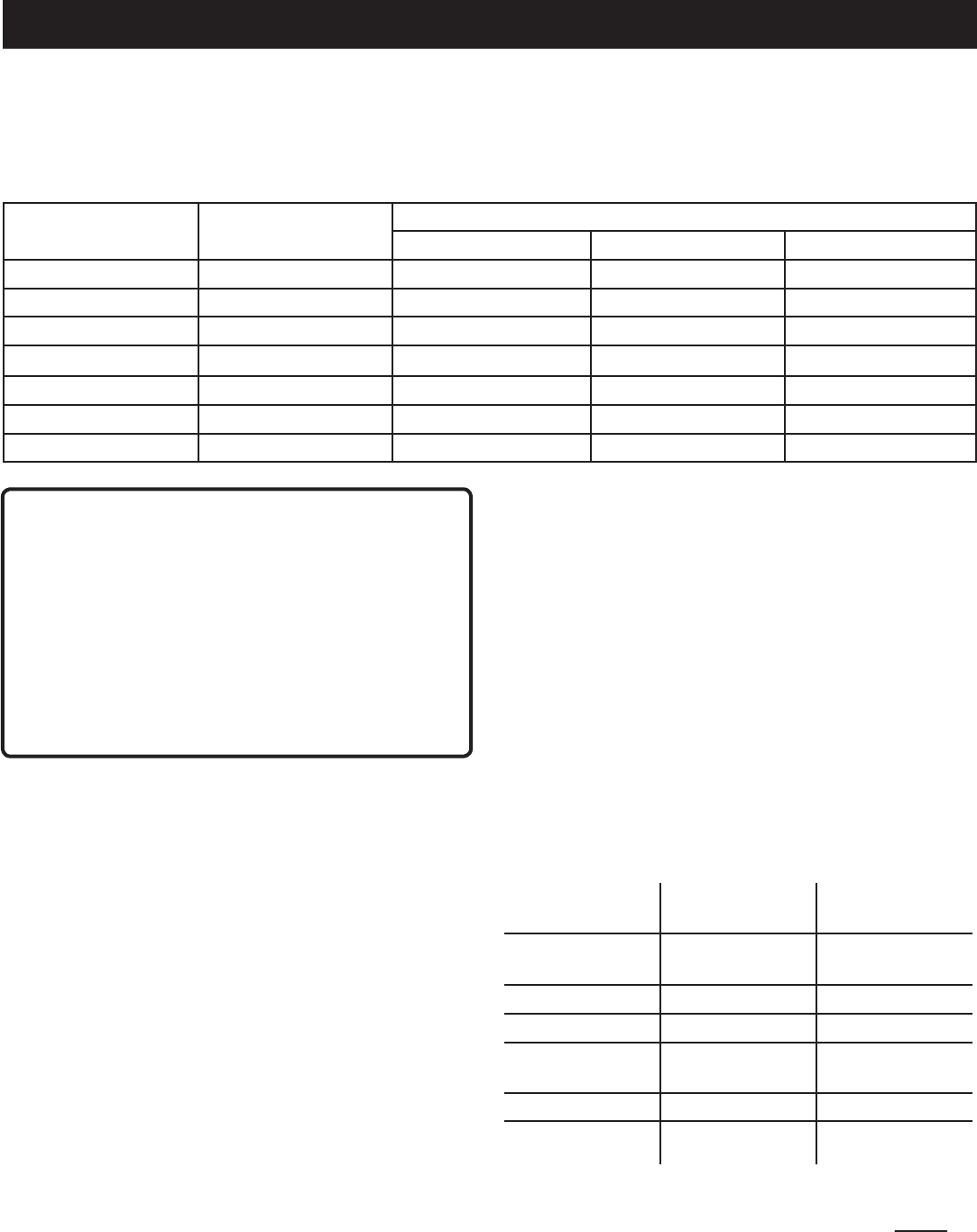
ELECTRICAL
EXTENSION CORD CABLE SIZE
Refer to the table below to ensure the cable size of the extension cords you use are capable of carrying the required load.
Inadequate size cables can cause a voltage drop, which can damage the appliance and overheat the cord.
Current in
Amperes
Load in Watts Maximum Allowable Cord Length
At 120V At 240V #8 Wire #10 Wire #12 Wire #14 Wire #16 Wire
2.5 300 600 1000 ft. 600 ft. 375 ft. 250 ft.
5 600 1200 500 ft. 300 ft. 200 ft. 125 ft.
7.5 900 1800 350 ft. 200 ft. 125 ft. 100 ft.
10 1200 2400 250 ft. 150 ft. 100 ft. 50 ft.
15 1800 3600 150 ft. 100 ft. 65 ft.
20 2400 4800 175 ft. 125 ft. 75 ft.
25 3000 6000 150 ft. 100 ft.
30 3600 7200 125 ft. 65 ft.
40 4800 9600 90 ft.
8 — English
ELECTRICAL
ELECTRIC MOTOR LOADS
It is characteristic of common electric motors in normal operation to draw up to six times their running current while start-
ing. This table may be used to estimate the watts required to start “Code G” electric motors; however, if an electric motor
fails to start or reach running speed, turn off the appliance or tool immediately to avoid equipment damage. Always check
the requirements of the tool or appliance being used compared to the rated output of the generator.
Motor Size (H.P.) Running Watts Watts Required to Start Motor
Repulsion Induction Capacitor Split Phase
1/8 275 600 850 1200
1/6 275 600 850 2050
1/4 400 850 1050 2400
1/3 450 975 1350 2700
1/2 600 1300 1800 3600
3/4 850 1900 2600 —
1 1100 2500 3300 —
CAUTION:
Operating voltage and frequency requirement of all
electronic equipment should be checked prior to plugging
them into this generator. Damage may result if the
equipment is not designed to operate within a +/- 10%
voltage variation, and +/- 3 hz frequency variation from the
generator name plate ratings. To avoid damage, always
have an additional load plugged into the generator if
solid state equipment (such as a television set) is used.
A power line conditioner is recommended for some solid
state applications.
GROUND FAULT CIRCUIT INTERRUPTER
See Figure 1.
The 20 amp, 120 volt receptacles on the generator are pro-
tected by a Ground Fault Circuit Interrupter (GFCI), which
guards against the hazards of ground fault currents. An
example of ground fault current is the current that would
flow through a person who is using an appliance with faulty
insulation and, at the same time, is in contact with an elec-
trical ground such as a plumbing fixture, wet floor, or earth.
GFCI receptacles do not protect against short circuits,
overloads, or shocks.
The GFCI receptacles can be tested with the TEST and
RESET buttons.
To test:
Depress the TEST button. This should cause the Reset
button to pop out.
To restore power, depress the RESET button.
Perform this test monthly to ensure proper operation of the
GFCI. If the generator is stored outdoors, unprotected from
the weather, test the GFCI receptacle before each use.
GENERATOR CAPACITY
Make sure the generator can supply enough continuous (run-
ning) and surge (starting) watts for the items you will power
at the same time. Follow these simple steps.
1. Selecttheitemsyouwillpoweratthesametime.
2. Totalthecontinuous(running)wattsoftheseitems.This
is the amount of power the generator must produce to
keep the items running. See the wattage reference chart
at right.
3. Estimatehowmanysurge(starting)wattsyouwillneed.
Surge wattage is the short burst of power needed to
start electric motor-driven tools or appliances such as a
circular saw or refrigerator. Because not all motors start
at the same time, total surge watts can be estimated by
adding only the item(s) with the highest additional surge
watts to the total rated watts from step 2.
Example:
Tool or Appliance Continuous
(Running) Watts
Surge
(Starting) Watts
Refrigerator 700 1350
Portable Fan 40 120
Laptop 250 250
46 in. Flat Panel
Television
190 190
Light (75 Watts) 75 75
1255 Total
Running Watts
1350 Highest
Surge Watts
Total Continuous (Running) Watts 1255
Plus Highest Additional Surge Watts + 1350
Equals Total Generator Output Required 2605
9 — English
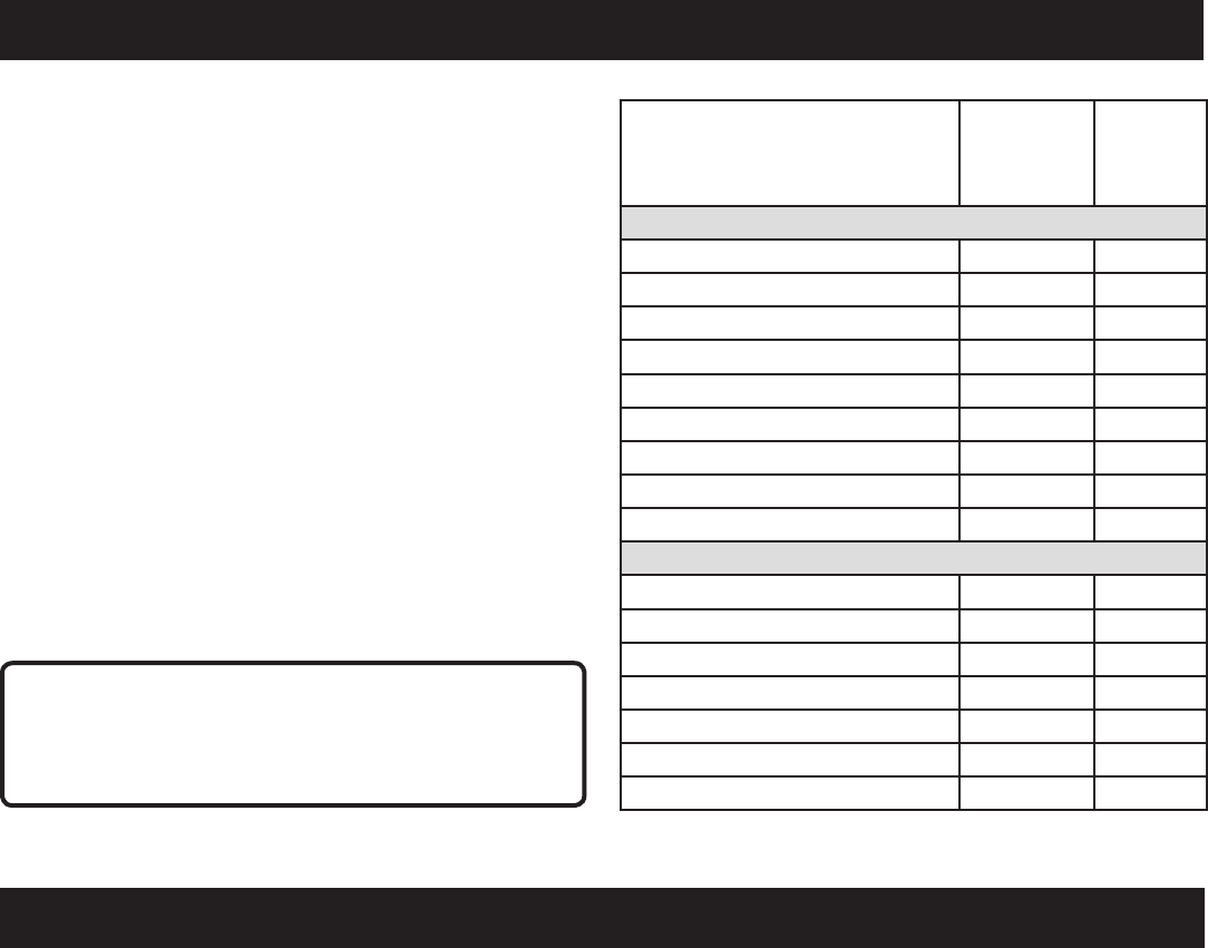
ELECTRICAL
Application/Equipment Estimated
Run Watts*
Estimated
Starting
Watts*
Emergency / Home Standby
Lights (qty. 4 x 75 W) 300 300
Refrigerator 700 1350
46 in. Flat Panel Television 190 190
Satelite Receiver 250 250
Portable Fan 40 120
Heater 1300 1300
Laptop 250 250
Slow Cooker 270 270
Radio 50 50
Job Site
ElectricDrill−3/8in. 600 1000
Quartz Halogen Work Light 1000 1000
Reciprocating Saw 960 1920
CircularSaw−7-1/4in. 1400 2300
MiterSaw−10in. 1800 1800
AirCompressor−1/4HP 970 1600
AirlessSprayer−1/3HP 600 1200
*Wattages listed are approximate. Check tool or appliance for actual wattage.
POWER MANAGEMENT
To prolong the life of the generator and attached devices,
it is important to take care when adding electrical loads to
the generator. There should be nothing connected to the
generator outlets before starting its engine. The correct and
safe way to manage generator power is to sequentially add
loads as follows:
1. With nothing connected to the generator, start the engine
as described later in this manual.
2. Plug in and turn on the first load, preferably the largest
load you have.
3. Permit the generator output to stabilize (engine runs
smoothly and attached device operates properly).
4. Plug in and turn on the next load.
5. Again, permit the generator to stabilize.
6. Repeat steps 4 and 5 for each additional load.
Never add more loads than the generator capacity. Take
special care to consider surge loads in generator capacity
as previously described.
CAUTION:
Do not overload the generator’s capacity. Exceeding the
generator’s wattage/amperage capacity can damage the
generator and/or electrical devices connected to it.
FEATURES
PRODUCT SPECIFICATIONS
ENGINE
Engine Type ......................... Single Overhead Cam (SOHC)
Bore x Stroke ............................................. 88 mm x 64 mm
Cooling System ...................................................Forced Air
Compression Ratio ...................................................... 8.5:1
Starting System ......................................................... Recoil
Ignition System ............................................................ T.C.I.
Spark Plug ................................................NHSP LD A7RTC
Engine Lubricant Volume......................................... 0.42 qt.
Fuel Volume ..............................................................1.0 gal.
GENERATOR
Rated Voltage .........................................120 V AC/12 V DC
Rated Amps ..........................................13.33A AC/7.5A DC
Rated Running Watts ............................................. 1,600 W
Starting Watts ......................................................... 2,000 W
Rated Frequency ........................................................ 60 Hz

10 — English
KNOW YOUR GENERATOR
See Figure 2.
The safe use of this product requires an understanding of the
information on the product and in this operator’s manual as
well as a knowledge of the project you are attempting. Before
use of this product, familiarize yourself with all operating
features and safety rules.
120 V AC RECEPTACLE
Your generator has two single phase, 60 Hz outlets that are
120 Volt AC, 20 Amp GFCI receptacles. These can be used
for operating appropriate appliances, electrical lighting,
tools, and motor loads.
AIR FILTER
The air filter help to limit the amount of dirt and dust drawn
into the unit during operation.
AUTO IDLE SWITCH
The auto idle switch is used to control the speed of the
engine and conserve fuel. When the switch is in the ON (I)
position and no appliances are connected to the unit, the
engine will idle. If an appliance is added, the engine speed
will increase to power the item. If the appliance is removed,
the engine will return to idle.
BATTERY CHARGING CABLE
Use the battery charging cable to connect 12 Volt lead acid
batteries to the generator.
NOTE: Only use battery charging cable to charge vented
wet lead acid batteries.
CARRY HANDLE
The generator has a carry handle for easy transport.
CHOKE LEVER
The choke lever is used when starting the engine.
DC CIRCUIT BREAKER
The circuit breaker is provided to protect the generator
against electrical overload.
DC RECEPTACLE
Your generator has a 12 V, 7.5 amp DC receptacle for
charging lead acid batteries.
WARNING:
The 12 V DC receptacle is designed to charge vented
wet lead acid batteries only. Other types of batteries may
burst, causing personal injury and damage.
ON/OFF SWITCH
The on/off switch is used in combination with the recoil
starter to start the generator. It is also used to turn the
generator off.
FUEL TANK
The fuel tank has a capacity of 1.0 gallon.
NOTE: The fuel flows from the fuel tank to the carburetor
only when the on/off switch is in the ON (I) position.
GROUND TERMINAL
The ground terminal is used to assist in properly ground-
ing the generator to help protect against electrical shock.
Consult with a local electrician for grounding requirements
in your area.
LED DISPLAY
LEDs provide feedback to indicate whether the generator is
in use, overloaded, or in need of lubricant.
OIL CAP/DIPSTICK
Remove the oil fill cap to check and add lubricant to the
generator when necessary.
RETRACTABLE HANDLE
The generator is equipped with a retractable handle that can
be adjusted for storage and transportation.
RECOIL STARTER
The recoil starter is used (along with the on/off switch) to
start the generator’s engine.
VENTED FUEL CAP
The generator has a fuel cap with a vent that can be opened
and closed. During normal operation the vent should be in
the open position.
FEATURES
11 — English
UNPACKING
This product has been shipped completely assembled.
Carefully remove the product and any accessories from
the box. Make sure that all items listed in the packing list
are included.
WARNING:
Do not use this product if any parts on the Packing List
are already assembled to your product when you unpack
it. Parts on this list are not assembled to the product by
the manufacturer and require customer installation. Use
of a product that may have been improperly assembled
could result in serious personal injury.
Inspect the product carefully to make sure no breakage
or damage occurred during shipping.
Do not discard the packing material until you have
carefully inspected and satisfactorily operated the
product.
If any parts are damaged or missing, please call
1-800-860-4050 for assistance.
PACKING LIST
Generator
Battery Charging Cable
Engine Lubricant (SAE 10W 30)
Spark Plug Wrench
Wrench Handle
Operator’s Manual
ASSEMBLY
WARNING:
If any parts are damaged or missing do not operate this
product until the parts are replaced. Use of this product
with damaged or missing parts could result in serious
personal injury.
WARNING:
Do not attempt to operate the generator until assembly
is complete. Failure to comply could result in possible
serious personal injury.
WARNING:
Do not attempt to modify this product or create acces-
sories not recommended for use with this product. Any
such alteration or modification is misuse and could result
in a hazardous condition leading to possible serious
personal injury.
12 — English
OPERATION
DANGER:
Carbon Monoxide. Using a generator indoors CAN KILL
YOU IN MINUTES.
Generator exhaust contains high levels of carbon
monoxide (CO), a poisonous gas you cannot see or smell.
If you can smell the generator exhaust, you are breathing
CO. But even if you cannot smell the exhaust, you could
be breathing CO.
Never use a generator inside homes, garages,
crawlspaces, or other partly enclosed areas. Deadly
levels of carbon monoxide can build up in these
areas. Using a fan or opening windows and doors
does NOT supply enough fresh air.
ONLY use a generator outdoors and far away from
open windows, doors, and vents. These openings
can pull in generator exhaust.
Even when you use a generator correctly, CO may
leak into the home. ALWAYS use a battery-powered or
battery-backup CO alarm in the home.
If you start to feel sick, dizzy, or weak after the generator
has been running, move to fresh air RIGHT AWAY. See
a doctor. You could have carbon monoxide poisoning.
DANGER:
Failure to properly ground generator can result in
electrocution, especially if the generator is equipped with
a wheel kit. National Electric Code requires generator to
be properly grounded to an approved earth ground. Call
an electrician for local grounding requirements.
WARNING:
Do not allow familiarity with this product to make you
careless. Remember that a careless fraction of a second
is sufficient to inflict serious injury.
WARNING:
Do not use any attachments or accessories not
recommended by the manufacturer of this product. The
use of attachments or accessories not recommended
can result in serious personal injury.
APPLICATIONS
This generator is designed to supply electrical power for
operating compatible electrical lighting, appliances, tools,
and motor loads.
BEFORE OPERATING THE UNIT
Only use OUTSIDE and far away from windows, doors,
and vents.
NEVER use inside a home or garage, EVEN IF doors and
windows are open.
Always position the generator on a flat firm surface.
LED DISPLAY
See Figure 3.
Power:
The power indicator will light when the generator is on and
the receptacles are operational.
NOTE: If the generator is overloaded, the power indicator
light will go off.
Overload:
The overload indicator will light if the generator’s wattage/
amperage capacity is exceeded. If the overload is slight, then
the unit will continue to function normally. If the overload is
severe, the 120V receptacle will switch off to protect the
generator’s electrical components. To reset the generator,
turn off the unit and remove all loads. The generator will not
reset unless the generator is turned off.
Lubricant:
The oil indicator will light and the engine will automatically
shut off whenever the lubricant level in the engine becomes
low. The engine may not be restarted until sufficient engine
lubricant has been added to the generator.
NOTE: It is normal for the indicator lights to illuminate and/
or blink each time the engine is started. Once the engine
warms up, the lights should default to the pattern above.
CAUTION:
Attempting to start the engine before it has been properly
filled with lubricant will result in equipment failure.
CHECKING/ADDING LUBRICANT
See Figure 4.
Engine lubricant has a major influence on engine perfor-
mance and service life. For general, all-temperature use,
SAE 10W-30 is recommended. Always use a 4-stroke motor
lubricant that meets or exceeds the requirements for API
service classification SJ.
NOTE: Non-detergent or 2-stroke engine lubricants will
damage the engine and should not be used.
Loosen the screw at the top of the engine cover. Remove
cover and set aside.
Unscrew the oil cap/dipstick and remove.
Wipe dipstick clean and re-seat in hole; do not re-thread.
Remove dipstick again and check lubricant level.
Lubricant level should fall between the minimum and
maximum marks on the dipstick.
If level is low, add engine lubricant until the fluid level
rises between the minimum and maximum marks on the
dipstick.
Replace and secure the oil cap/dipstick.
13 — English
OPERATION
CHECKING/ADDING FUEL
See Figure 5.
WARNING:
Gasoline is extremely flammable and explosive. A fire
or explosion from gasoline will burn you and others.
Always shut off engine before fueling. Never add fuel to a
machine with a running or hot engine. Move at least 30 ft.
from refueling site before starting engine. Do not smoke
and stay away from open flames and sparks. Failure to
safely handle fuel could result in serious personal injury.
Remove the fuel cap.
Fill the fuel tank to 1 in. below the top of the fuel neck.
Replace the fuel cap and tighten until it clicks.
NOTE: Always use unleaded gasoline with a pump octane
rating of 86 or higher. Never use old, stale, or contaminated
gasoline, and do not use an oil/gas mixture. Do not allow dirt
or water into the fuel tank. Do not use E85 fuel.
WARNING:
Check for fuel leaks. A leaking fuel cap is a fire hazard
and must be replaced immediately. If you find any leaks,
correct the problem before using the product. Failure
to do so could result in a fire that could cause serious
personal injury.
USING FUEL STABILIZER
Fuel gets old, oxidizes, and breaks down over time. Adding
a fuel stabilizer (not included) extends the usable life of fuel
and helps prevent deposits from forming that can clog the
fuel system. Follow fuel stabilizer manufacturer’s directions
for correct ratio of stabilizer to fuel.
Add stabilizer to fuel tank, then fill with gasoline following
previous instructions.
NOTE: Fuel stabilizer and gasoline can be mixed prior to
filling the tank by using a gas can or other approved fuel
container and shaking gently to combine.
Replace and secure the fuel tank cap.
Start and run the engine for at least 5 minutes to allow
stabilizer to treat the entire fuel system.
OXYGENATED FUELS
DO NOT USE E15 OR E85
FUEL IN THIS UNIT. IT IS A
VIOLATION OF FEDERAL LAW
AND WILL DAMAGE THE UNIT
AND VOID YOUR WARRANTY.
NOTE: Fuel system damage or performance problems
resulting from the use of an oxygenated fuel containing
more than the percentage of oxygenates stated below are
not covered under warranty.
Ethanol. Gasoline containing up to 10% ethanol by volume
(commonly referred to as E10) is acceptable. E15 and E85
are not.
OPENING AND CLOSING VENTED FUEL CAP
See Figures 6 - 7.
The generator has a fuel cap with a vent that can be opened
and closed.
To open the vent, rotate the fuel cap lever to the ON (I)
position. The vent should be open during operation.
To close the vent, rotate the fuel cap lever to the OFF (O)
position. The vent should be closed when the generator
is not in use.
CAUTION:
On a level surface with the engine off, check the lubricant
level before each use of the generator.
CAUTION:
Do not place the generator directly on the ground when
using the unit in grassy areas or in areas with dense
vegetation. Doing so could result in grass discoloration
and/or localized soil damage.
STARTING THE ENGINE
See Figures 8 - 11.
NOTE: If location of generator is not level, the unit may not
start or may shut down during operation.
Unplug all loads from the generator.
Put the auto idle switch in the OFF position.
Open the vent on the fuel cap by rotating the fuel cap
lever to the ON (I) position.
Put the on/off switch in the ON ( I ) position.
NOTE: When the on/off switch is in the ON (I) position
fuel will flow from the fuel tank to the engine.
Move the choke lever right to the START position.
NOTE: If engine is warm, move the choke lever left to
the RUN position.
Pull the recoil starter until the engine runs (a maximum
of 6 times).
NOTE: Do not allow the grip to snap back after starting;
return it gently to its original place.
Allow the engine to run for 15 - 30 seconds, then move
the choke lever left to the RUN position.
STOPPING THE ENGINE
See Figures 7 - 10.
Remove any load from the generator.
Put the on/off switch in the OFF ( O ) position.
Close the vent on the fuel cap by rotating the fuel cap
lever to the OFF (O) position.
NOTE:Ifthetemperatureisabove75˚F,leavethevent
on the fuel cap open to relieve pressure.
14 — English
OPERATION
To stop the engine in an emergency situation:
Put the on/off switch in the OFF ( O ) position.
USING THE BATTERY CHARGING CABLE
See Figure 12.
WARNING:
The 12V DC receptacle is designed to charge vented wet
lead acid batteries only. Other types of batteries may
burst, causing personal injury and damage.
CAUTION:
The 12 V DC receptacle provides continuous charge. Do
not overcharge battery or leave battery unattended. Doing
so may cause damage to the battery.
CAUTION:
Do not use the generator to jump start vehicles. Doing
so could result in damage to the vehicle or it’s electrical
components.
Using the battery clamps, connect the battery charging
cable assembly to the battery terminal. Connect the
red wire to the positive (+) terminal first, then connect
the black wire to the negative (–) terminal. Make sure all
connections are secure.
NOTE: Be careful not to short across the terminals when
installing. Shorting the terminals together can cause
sparks, damage to the battery or generator, or even burns
or explosions.
Connect the battery charging cable assembly to the
12 V DC receptacle.
Start the generator.
NOTE: The AC receptacles can be used while the DC
receptacle is in use.
The battery will become slightly warm to the touch while
charging. This is normal and does not indicate a problem.
NOTE: Only use battery charging cable assembly to
charge vented wet lead acid batteries.
When batteries become fully charged, disconnect
the battery charging cable assembly from the battery.
Disconnect the negative (black) wire first, then the positive
(red) wire, being careful not to short across the terminals.
Always abide by the safety warnings provided with the
battery.
NOTE: Most batteries will be completely charged after
30 to 120 minutes. However, it is highly recommended
that you refer to your battery manufacturer’s instructions
for specific charge times.
Unplug battery charging cable assembly and store for
later use.
MOVING THE GENERATOR
See Figure 13.
Put the on/off switch in the OFF ( O ) position.
Allow 30 minutes of “cool down” time before storing the
machine.
Pull the retractable handle out.
Facing the back of the generator, grasp the folding handle
firmly with one hand.
Lift the generator toward you until it balances on the
wheels.
Turn around and pull the unit along behind you to the
desired location.
Lower the generator until it sits securely on a flat surface.
MAINTENANCE
WARNING:
When servicing, use only identical replacement parts.
Use of any other parts may create a hazard or cause
product damage.
WARNING:
Always wear eye protection with side shields marked to
comply with ANSI Z87.1. Failure to do so could result in
objects being thrown into your eyes, resulting in possible
serious injury.
GENERAL MAINTENANCE
Keep the generator in a clean and dry environment where it
is not exposed to dust, dirt, moisture, or corrosive vapors.
Do not allow the cooling air slots in the generator to become
clogged with foreign material such as leaves, etc.
Do not use a garden hose to clean the generator. Water
entering the fuel system or other internal parts of the unit can
cause problems that will decrease the life of the generator.
To clean the unit:
Use a soft bristle brush and/or vacuum cleaner to loosen
and remove dirt and debris.
Clean air vents with low pressure air that does not exceed
25 psi.
Wipe the exterior surfaces of the generator with a damp cloth.
15 — English
MAINTENANCE
Measurepluggap.Thecorrectgapis0.024−0.028in.
(0.60-0.70 mm). To widen gap, if necessary, carefully
bend the ground (top) electrode. To lessen gap, gently
tap ground electrode on a hard surface.
Seat spark plug in position; thread in by hand to prevent
cross-threading.
Tighten with wrench to compress washer. If spark plug
is new, use 1/2 turn to compress washer appropriate
amount. If reusing old spark plug, use 1/8 to 1/4 turn for
proper washer compression.
NOTE: An improperly tightened spark plug will become
very hot and could damage the engine.
CAUTION:
Be careful not to cross-thread the spark plug. Cross-
threading will seriously damage the product.
DRAINING FUEL TANK/CARBURETOR
See Figures 18 - 19.
To help prevent gum deposits in the fuel system, drain the
fuel from the tank and carburetor before storing.
Draining The Fuel Tank:
CAUTION:
Remove all lubricant from the unit before draining the fuel
tank. Failure to do so could cause damage to the unit.
Remove the fuel cap.
Tilt the generator and allow fuel to drain from the fuel tank
into an approved container.
When the fuel has drained from the tank, replace the fuel
cap.
Draining The Carburetor:
Put the on/off switch in the ON ( I ) position.
Loosen the screw at the top of the engine cover. Remove
cover and set aside.
Position a suitable container under the carburetor drain
screw to catch fuel; loosen the screw.
Allow fuel to drain completely into container.
Retighten drain screw securely.
Put the on/off switch in the OFF ( O ) position.
NOTE: Consult hazardous waste management guidelines in
your area for the proper way to dispose of used fuel.
TRANSPORTING
Put the on/off switch in the OFF ( O ) position.
Make sure engine and exhaust of unit is cool.
Keep unit level to prevent fuel spillage.
Do not drop or strike unit or place under heavy objects.
CHECKING/CLEANING AIR FILTER
See Figures 14 - 15.
For proper performance and long life, keep air filter clean.
Loosen the screw at the top of the engine cover. Remove
cover and set aside.
Loosen the screw in the center of the air filter cover.
Remove air filter cover and set aside.
Remove both the large and the small air filter.
Wash the air filters with warm, soapy water. Rinse and
squeeze to dry.
Reinstall the air filters.
NOTE: Make sure the filters are seated properly inside
the generator. Installing the filters incorrectly will allow
dirt to enter the engine, causing rapid engine wear.
Install the air filter cover. Tighten screw to secure.
Install the engine cover. Tighten screw to secure.
CHANGING ENGINE LUBRICANT
See Figure 16.
For best performance, engine lubricant should be changed
after every 100 hours or 6 months of operation.
Loosen the screw at the top of the engine cover. Remove
cover and set aside.
Remove the oil fill cap/dipstick.
Tilt the generator to the side and allow lubricant to drain
from the oil fill hole into an approved container.
NOTE: Drain the lubricant while the engine is still warm
but not hot. Warm lubricant will drain quickly and more
completely.
Return the generator to an upright position and refill with
lubricant following the instructions in the Checking/
Adding Lubricant section previously in this manual.
Replace and secure the oil cap/dipstick.
Reinstall the engine cover. Replace the screw and tighten
securely.
NOTE: Used lubricant should be disposed of at an approved
disposal site. See your local retailer for more information.
SPARK PLUG REPLACEMENT
See Figure 17.
The spark plug must be properly gapped and free of deposits
in order to ensure proper engine operation. To check:
Remove the spark plug cover.
Remove the spark plug cap.
Clean any dirt from around base of spark plug.
Remove spark plug using spark plug wrench.
Inspect spark plug for damage, and clean with a wire
brush before reinstalling. If insulator is cracked or
chipped, spark plug should be replaced.
NOTE: If replacing, use the following recommended
spark plug or equivalent: NHSP LD A7RTC.
16 — English
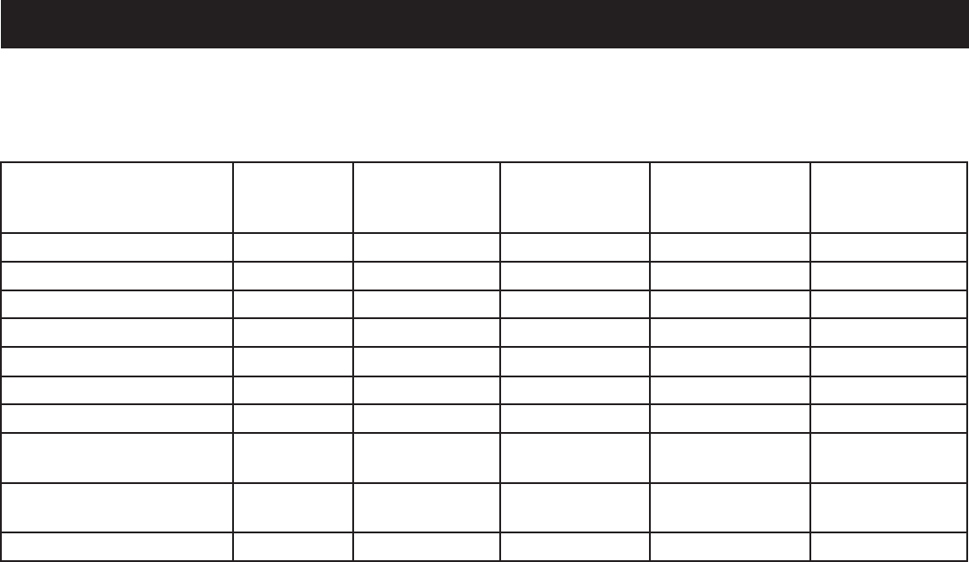
MAINTENANCE SCHEDULE
NOTE: If a separate engine manual is provided for this generator, please follow the maintenance schedule provided in the
engine manual instead of the maintenance information listed below.
Before
each use
After 1st month
or 10 hours of
operation
Every 3 months
or 50 hours of
operation
Every 6 months
or 100 hours
of operation
Every year or
after 300 hours
of operation
Check Engine Lubricant
Change Engine Lubricant
Check Air Filter
Clean Air Filter2
Change Air Filter2
Check/Adjust Spark Plug
Replace Spark Plug2
Check/Adjust Valve
Clearance1,2
Clean Fuel Tank and
Filter1
Check Fuel Tube
1. These items should only be carried out by an authorized service center.
2. See engine manual for maintenance schedule for this item.
NOTE: Maintenance should be performed more frequently when generator is used in dusty areas. When generator has
exceeded the maximum figures specified in the table, maintenance should still be cycled according to the intervals of
time or hours stated herein.
MAINTENANCE
17 — English
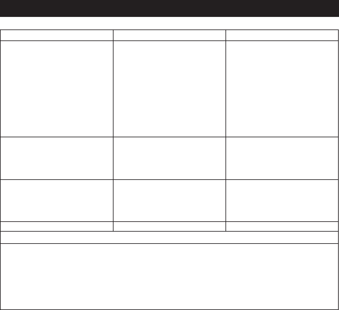
TROUBLESHOOTING
PROBLEM POSSIBLE CAUSE SOLUTION
Engine will not start. The on/off switch is on OFF (O).
No fuel.
Lubricant level is low.
Spark plug faulty, fouled, or improperly
gapped.
Choke lever is in RUN position.
Engine stored without treating or
draining gasoline, or refueled with bad
gasoline.
Dirty fuel filter.
Turn the on/off switch to ON (I).
Fill fuel tank.
Check engine lubricant level and fill, if
necessary.
Replace spark plug.
Move choke lever to START position.
Drain fuel and carburetor. Refuel with
fresh gasoline.
Contact authorized service center.
Engine lacks power. Engine stored without treating or
draining gasoline, or refueled with bad
gasoline.
Dirty air filter.
Drain fuel and carburetor. Refuel with
fresh gasoline. If problem continues,
contact your nearest authorized service
center.
Clean or replace as needed.
DC receptacle does not work. Circuit protector engaged
Item plugged in is defective.
Remove any load from the generator.
Turn the on/off switch to OFF (O), then
depress the DC circuit breaker. See
Figure 20.
Try a different item.
AC receptacle does not work. Item plugged in is defective. Try a different item.
If problem persists after trying the above solutions, contact your nearest authorized service center for assistance.
The following symptoms may indicate problems that will affect the emissions level of the unit:
Hard starting or stalling after starting
Rough idle
Misfiring or backfiring under load
Afterburning (backfiring)
Black exhaust smoke or high fuel consumption
If you encounter any of these symptoms, have the unit inspected and repaired by the nearest authorized service center.

18 — English
WARRANTY
YOUR WARRANTY RIGHTS AND OBLIGATIONS
The United States Environmental Protection Agency (EPA) and Yongkang Zhongjian Tools Manufacture Co., Ltd
(Zhongjian) are pleased to explain the Emission Control System Warranty on your new small off-road engine. New
small off-road engines must be designed, built and equipped to meet stringent EPA anti-smog standards. Zhongjian
must warrant the emission control system on your small off-road engine for the periods of time listed below provided
there has been no abuse, neglect, unapproved modification or improper maintenance of your engine.
Your emission control system may include parts such as: carburetor, ignition system, intake and exhaust systems, and
other associated components. Zhongjian will repair your engine at no cost to you for diagnosis, replacement parts
and labor, should a warrantable condition occur.
MANUFACTURER’S EMISSION CONTROL SYSTEM WARRANTY COVERAGE:
Emission control systems on 2011 and later model year engines are warranted for 2 years as hereinafter noted. If, during
such warranty period, any emission-related component or system on your engine is found to be defective in materials
or workmanship, repairs or replacement will be performed by a Zhongjian Authorized Warranty Service Facility.
PURCHASER’S/OWNER’S WARRANTY RESPONSIBILITIES:
As the small off-road engine purchaser/owner, you are responsible for the completion of all required maintenance as
listed in your factory supplied Owner’s Manual. For warranty purposes, Zhongjian recommends that you retain all
receipts covering maintenance on your engine. However, Zhongjian cannot deny warranty solely because of the lack
of receipts or for your failure to ensure the completion of all scheduled maintenance.
As the small off-road engine purchaser/owner, you should, however, be aware that Zhongjian may deny any and/or
all warranty coverage or responsibility if your engine, or a part/component thereof, has failed due to abuse, neglect,
improper maintenance or unapproved modifications, or the use of counterfeit and/or “grey market” parts not made,
supplied or approved by Zhongjian.
You are responsible for presenting your engine to a Zhongjian Authorized Warranty Service Facility as soon as a
problem occurs. The warranty repairs should be completed in a reasonable amount of time, not to exceed 30 days.
Warranty service can be arranged by contacting either your selling dealer or a Zhongjian Authorized Warranty Service
Facility. To locate the Zhongjian Authorized Warranty Service Facility nearest you call 1-800-860-4050.
EPA EMISSION CONTROL WARRANTY STATEMENT

19 — English
WARRANTY
YOUR WARRANTY RIGHTS AND OBLIGATIONS
The California Air Resources Board and Yongkang
ZhongJian Tools manufacture Co., Ltd. are pleased to
explain the emissions control system warranty on your
2011 and later small off-road engine (SORE). In California,
new SOREs must be designed, built and equipped to
meet the State’s stringent anti-smog standards. Yongkang
ZhongJian Tools manufacture Co., Ltd. must warrant the
emissions control system on your SOREs for the periods
of time listed below provided there has been no abuse,
neglect or improper maintenance of your SOREs.
Your emission control system may include parts such as
the carburetor, fuel tanks, fuel caps, fuel lines, the ignition
system, and catalytic converter. Also included may be
hoses, belts, clamps, connectors and other emission-
related assemblies.
Where a warrantable condition exists, Yongkang
ZhongJian Tools manufacture Co., Ltd. will repair your
small off-road engine at no cost to you including diagnosis,
parts and labor.
MANUFACTURER’S WARRANTY COVERAGE:
The emissions control system is warranted for two years. If
any emissions-related part on your engine is defective, the
part will be repaired or replaced by Yongkang ZhongJian
Tools manufacture Co., Ltd.
OWNER’S WARRANTY RESPONSIBILITIES:
As the SORE owner, you are responsible for the
performance of the required maintenance listed in
your owner’s manual. Yongkang ZhongJian Tools
manufacture Co., Ltd. recommends that you retain
all receipts covering maintenance on your SORE, but
Yongkang ZhongJian Tools manufacture Co., Ltd. can
not deny warranty solely for the lack of receipts or for
your failure to ensure the performance of all scheduled
maintenance.
As the SORE owner, you should however be aware
that Yongkang ZhongJian Tools manufacture Co.,
Ltd. may deny your warranty coverage if your SORE
or a part has failed due to abuse, neglect, improper
maintenance or unapproved modifications.
You are responsible for presenting your SORE to
distribution center or service center authorized by
Yongkang ZhongJian Tools manufacture Co., Ltd.
as soon as the problem exists. The warranty repairs
should be completed in a reasonable amount of time,
not to exceed 30 days.
If you have any questions regarding your warranty
coverage, you should contact Yongkang ZhongJian Tools
manufacture Co., Ltd. customer service representative at
1-877-218-5285.
CALIFORNIA EMISSIONS CONTROL WARRANTY STATEMENT
DEFECTS WARRANTY COVERAGE:
Adopted by the Air Resources Board, Yongkang ZhongJian
Tools manufacture Co., Ltd. warrants to the ultimate
purchaser and each subsequent purchaser that the small
off-road engine (SORE) (1) has been designed, built and
equipped so as to conform with all applicable regulations;
and (2) is free from defects in materials and workmanship
that cause the failure of a warranted part to conform with
those regulations as may be applicable to the terms and
conditions stated below.
(a) The warranty period begins on the date the engine
is delivered to an ultimate purchaser. The warranty
period is two years.
(b) Subject to certain conditions and exclusions as
stated below, the warranty on emissions related
parts is as follows:
(1) Any warranted part that is not scheduled for
replacement as required maintenance in your Owner’s
Manual is warranted for the warranty period stated
above. If the part fails during the period of warranty
coverage, the part will be repaired or replaced by
Yongkang ZhongJian Tools manufacture Co., Ltd.
according to Subsection (4) below. Any such part
repaired or replaced under warranty will be warranted
for the remainder of the period.
(2) Any warranted part that is scheduled only for regular
inspection in your Owner’s Manual is warranted for the
warranty period stated above. Any such part repaired
or replaced under warranty will be warranted for the
remaining warranty period.
(3) Any warranted part that is scheduled for replacement
as required maintenance in your Owner’s Manual
is warranted for the period of time before the first
scheduled replacement date for that part. If the part
fails before the first scheduled replacement, the part
will be repaired or replaced by Yongkang ZhongJian
Tools manufacture Co., Ltd. according to Subsection
(4) below. Any such part repaired or replaced under
warranty will be warranted for the remainder of the
period prior to the first scheduled replacement point
for the part.
(4) Repair or replacement of any warranted part under
the warranty provisions herein must be performed at
a warranty station at no charge to the owner.
(5) Notwithstanding the provisions herein, warranty
services or repair will be provided at all of our
distribution centers that are franchised to service the
subject engines.
(6) The engine owner must not be charged for diagnostic
labor that leads to the determination that a warranted
part is in fact defective, provided that such diagnostic
work is performed at a warranty station.

20 — English
WARRANTY
(7) Yongkang ZhongJian Tools manufacture Co., Ltd.
is liable for damages to other engine components
proximately caused by a failure under warranty of any
warranted part.
(8) Throughout the engine warranty period stated above,
Yongkang ZhongJian Tools manufacture Co., Ltd. will
maintain a supply of warranted parts sufficient to meet
the expected demand for such parts.
(9) Any replacement part may be used in the performance
of any warranty maintenance or repairs and must
be provided without charge to the owner. Such use
will not reduce the warranty obligations of Yongkang
ZhongJian Tools manufacture Co., Ltd.
(10) Add-on or modified parts that are not exempted by
the Air Resources Board may not be used. The use
of any non-exempted add-on or modified parts by
the ultimate purchaser will be grounds for disallowing
a warranty claims. Yongkang ZhongJian Tools
manufacture Co., Ltd. will not be liable to warrant
failures of warranted parts caused by the use of a
non-exempted add-on or modified part.
(11) The manufacturer issuing the warranty shall provide
any documents that describe that manufacturer’s
warranty procedures or policies within five working
days of request by the Air Resources Board.
WARRANTY PERIODS:
The repair or replacement of any warranted part otherwise
eligible for warranty coverage may be excluded from
such warranty coverage if Yongkang ZhongJian Tools
manufacture Co., Ltd. demonstrates that the engine has
been abused, neglected, or improperly maintained, and
that such abuse, neglect, or improper maintenance was
the direct cause of the need for repair or replacement
of the part. That notwithstanding, any adjustment of a
component that has a factory installed, and properly
operating, adjustment limiting device is still eligible for
warranty coverage. The following emissions warranty
parts for each engine family list is covered.
For engine families BZJTS.0404YY and BZJTS.0541YY:
(1) Fuel Metering System:
(a) Gasoline carburetor assembly and its internal
components (if so equipped)
(b) Fuel filter (if so equipped)
(c) Carburetor gaskets
(d) Fuel pump (if so equipped)
(2) Air Induction System including:
(a) Intake pipe/manifold
(b) Air cleaner
(3) Ignition System including:
(a) Spark plug
(b) Ignition module/coil
CALIFORNIA EMISSIONS CONTROL WARRANTY STATEMENT (continued)
(4) Catalytic Muffler Assembly (if so equipped) including:
(a) Muffler gasket
(b) Exhaust manifold
(5) Crankcase Breather Assembly including:
(a) Breather connection tube.
(6) Miscellaneous items Used in Above Systems including:
(a) Switches
(b) Hoses, belts, connectors, and assemblies.
(7) Fuel tank evaporative emissions control system
including:
(a) Fuel Tank
For engine family BZJTS.1061YY :
(1) Fuel Metering System:
(a) Gasoline carburetor assembly and its internal
components
(b) Carburetor gaskets
(c) Fuel tank
(f) Fuel Line
(g) Fuel Line Fittings
(h) Clamps
(2) Air Induction System including:
(a) Intake pipe/manifold
(b) Air cleaner
(3) Ignition System including:
(a) Spark plug
(b) Ignition coil
(4) Catalytic Muffler Assembly (if so equipped) including:
(a) Muffler gasket
(b) Exhaust manifold
(c) Catalytic converter
(5) Crankcase Breather Assembly including:
(a) Breather connection tube.
(6) Fuel tank evaporative emissions control system
including:
(a) Purge Valves
(b) Carbon Canister
(c) Canister Mounting Brackets
(d) Fuel Cap
(e) Fuel Tank
(6) Miscellaneous items Used in Above Systems including:
(a) Switches
(b) Hoses, belts, connectors, and assemblies.
(7) Air injection system
(a) Pulse valve
The warranty is provided in accordance with the “California
Emission Control Warranty Statement”.

21 — English
WARRANTY
Techtronic Industries North America, Inc. (herein
“Techtronic Industries”), warrants that each new engine
sold by it will be free, under normal use and service,
from defects in material and workmanship for a period
listed below from the date of sale to the original retail
purchaser. Techtronic Industries obligation under this
Limited Warranty shall be limited to the repair and
replacement, at Techtronic Industries option, of any part or
parts which upon examination is/are found, in Techtronic
Industries judgment, to have been defective in material or
workmanship. It shall be a condition of Techtronic Industries
obligation under this Limited Warranty that Techtronic
Industries, directly or through one of its Distributors or
Service Centers authorized to service the particular engine
involved, receive prompt notice of any warranty claim
and that the engine or the part or parts claimed to be
defective be promptly delivered, transportation prepaid,
to such Distributor or Service Center for inspection and
repair. All repairs qualifying under this Limited Warranty
must be performed by Techtronic Industries or one of its
authorized Distributors or Service Centers.
WARRANTY PERIODS:
158F Gasoline Engine (Private/Residential) Limited 2
year Warranty
158F Gasoline Engines (Commercial) Limited 90 Day
Warranty
The repair or replacement of any part or parts under this
Limited Warranty shall not extend the term of the engine
warranty beyond the original term as set forth above.
LIMITATIONS AND EXCLUSIONS: This Limited Warranty
shall not apply to:
1. Repair required because of prolonged storage including
damage caused by old or contaminated fuel in the fuel
tank, fuel lines, or carburetor, sticky valves or corrosion
and rust of engine parts.
2. Repair required due to overheating. (Most often caused
by overloaded or clogged or damaged or missing flywheel,
fan, inlet air passages, cooling fins, or air shrouds.)
3. Dirt or grit related wear caused by improper air cleaner
maintenance (most often resulting in worn piston, piston
LIMITED ENGINE WARRANTY
rings, cylinders, valves, valve guides, carburetor, or other
internal components).
4. Broken or scored parts caused by low oil level, dirty,
or improper grade of oil.
5. Engine tune-ups and normal maintenance service
including, but not limited to, valve adjustment, normal
replacement of service items, fuel, and lubricating oil, etc.
6. Any engine which has been subject to negligence,
misuse, accident, misapplication, or overspeeding.
7. Any engine that has been installed, repaired, or altered
by anyone in a manner which in Techtronic Industries sole
judgment adversely affects its performance or reliability.
8. Any engine which has been fitted with or repaired with
parts or components not manufactured or approved by
Techtronic Industries which in Techtronic Industries’ sole
judgment adversely affects its performance or reliability.
9. Instances when normal use has exhausted the life of
a component or an engine.
The customer is responsible for all transportation charges
in connection with any warranty work.
Techtronic Industries reserves the right to modify, alter,
or improve any engines or parts without incurring any
obligation to modify or replace any engine or parts
previously sold without such modification, alternation,
or improvement.
No person is authorized to give any other warranty or to
assume any additional obligation on Techtronic Industries’
behalf unless made in writing and signed by an officer of
Techtronic Industries.
THIS WARRANTY, TECHTRONIC INDUSTRIES
OBLIGATION HERE UNDER, ARE IN LIEU OF ANY
OTHER WARRANTIES OR OBLIGATIONS OF ANY
KIND, EXPRESSED OR IMPLIED, INCLUDING ANY
WARRANTIES OF MERCHANTABILITY OR FITNESS
FOR A PARTICULAR PURPOSE. THERE ARE NO
WARRANTIES WHICH EXTEND BEYOND THE
DESCRIPTION ON THE FACE HERE-OF. TECHTRONIC
INDUSTRIES SHALL IN NO EVENT BE LIABLE FOR
ANY CONSEQUENTIAL OR INCIDENTAL DAMAGES.
IF YOU HAVE ANY QUESTIONS REGARDING YOUR WARRANTY RIGHTS AND RESPONSIBILITIES, CONTACT
YOUR NEAREST AUTHORIZED RYOBI SERVICE CENTER AT 1-800-860-4050.

22 — English
WARRANTY
LIMITED WARRANTY STATEMENT
Techtronic Industries North America, Inc., warrants to the
original retail purchaser that this RYOBI® brand outdoor
product is free from defect in material and workmanship
and agrees to repair or replace, at Techtronic Industries
North America, Inc.’s, discretion, any defective product
free of charge within these time periods from the date of
purchase.
Three years if the product is used for personal, family
or household use;
90 days, if used for any other purpose, such as
commercial or rental.
This warranty extends to the original retail purchaser only
and commences on the date of the original retail purchase.
Any part of this product found in the reasonable judgment
of Techtronic Industries North America, Inc. to be defective
in material or workmanship will be repaired or replaced
without charge for parts and labor by an authorized service
center for RYOBI® brand outdoor products (Authorized
Ryobi Service Center).
The product, including any defective part, must be returned
to an authorized Ryobi service center within the warranty
period. The expense of delivering the product to the service
center for warranty work and the expense of returning it
back to the owner after repair or replacement will be paid
by the owner. Techtronic Industries North America, Inc.’s,
responsibility in respect to claims is limited to making the
required repairs or replacements and no claim of breach of
warranty shall be cause for cancellation or rescission of the
contract of sale of any RYOBI® brand outdoor product. Proof
of purchase will be required by the dealer to substantiate
any warranty claim. All warranty work must be performed
by an authorized service center.
This warranty is limited to ninety (90) days from the date
of original retail purchase for any RYOBI® brand outdoor
product that is used for rental or commercial purposes, or
any other income-producing purpose.
This warranty does not cover any product that has been
subject to abuse, misuse, neglect, negligence, accident,
the effects of corrosion or erosion, or that has been
operated in any way contrary to the operating instructions
as specified in this operator’s manual. This warranty does
not apply to any damage to the product that is the result
of improper maintenance or to any product that has been
altered or modified. The warranty does not extend to
repairs made necessary by normal wear or by the use of
parts or accessories which are either incompatible with
the RYOBI® brand outdoor product or adversely affect
its operation, performance, or durability.
In addition, this warranty does not cover:
Tune-ups – Spark Plugs, Carburetor, Carburetor
Adjustments, Ignition, Filters, Oil Change
Wear items – Recoil Starter Rope, Motor Brushes, Alternator
Brushes, Cotter Pins, Wheels, a High Pressure Hose,
Spray Wand, Nozzles, Trigger Handle, Supply Hoses,
Quick Couplers, Gaskets, Valves, Pistons, Pump Valve
Assemblies, O-Rings, Water and Oil Seals, Detergent Tanks.
The Company will not pay for repairs or adjustments to
the Product, or for any costs or labor, performed without
the Company’s prior authorization.
Techtronic Industries North America, Inc., reserves the
right to change or improve the design of any RYOBI®
brand outdoor product without assuming any obligation
to modify any product previously manufactured.
ALL IMPLIED WARRANTIES ARE LIMITED IN DURATION
TO THE STATED WARRANTY PERIOD. ACCORDINGLY,
ANY SUCH IMPLIED WARRANTIES INCLUDING
MERCHANTABILITY, FITNESS FOR A PARTICULAR
PURPOSE, OR OTHERWISE, ARE DISCLAIMED
IN THEIR ENTIRETY AFTER THE EXPIRATION OF
THE APPROPRIATE THREE-YEAR OR NINETY-DAY
WARRANTY PERIOD. TECHTRONIC INDUSTRIES
NORTH AMERICA, INC.’S, OBLIGATION UNDER THIS
WARRANTY IS STRICTLY AND EXCLUSIVELY LIMITED TO
THE REPAIR OR REPLACEMENT OF DEFECTIVE PARTS
AND TECHTRONIC INDUSTRIES NORTH AMERICA,
INC., DOES NOT ASSUME OR AUTHORIZE ANYONE
TO ASSUME FOR THEM ANY OTHER OBLIGATION.
SOME STATES DO NOT ALLOW LIMITATIONS ON HOW
LONG AN IMPLIED WARRANTY LASTS, SO THE ABOVE
LIMITATION MAY NOT APPLY TO YOU. TECHTRONIC
INDUSTRIES NORTH AMERICA, INC., ASSUMES NO
RESPONSIBILITY FOR INCIDENTAL, CONSEQUENTIAL,
OR OTHER DAMAGES INCLUDING, BUT NOT LIMITED
TO, EXPENSE OF RETURNING THE PRODUCT TO AN
AUTHORIZED RYOBI SERVICE CENTER AND EXPENSE
OF DELIVERING IT BACK TO THE OWNER, MECHANIC’S
TRAVEL TIME, TELEPHONE OR TELEGRAM CHARGES,
RENTAL OF A LIKE PRODUCT DURING THE TIME
WARRANTY SERVICE IS BEING PERFORMED, TRAVEL,
LOSS OR DAMAGE TO PERSONAL PROPERTY, LOSS
OF REVENUE, LOSS OF USE OF THE PRODUCT, LOSS
OF TIME, OR INCONVENIENCE. SOME STATES DO NOT
ALLOW THE EXCLUSION OR LIMITATION OF INCIDENTAL
OR CONSEQUENTIAL DAMAGES, SO THE ABOVE
LIMITATION OR EXCLUSION MAY NOT APPLY TO YOU.
This warranty gives you specific legal rights, and you may
also have other rights which vary from state to state.
This warranty applies this Ryobi® brand outdoor product
manufactured by or for Techtronic Industries North America,
Inc., and sold in the United States and Canada.
To locate your nearest Authorized Ryobi Service Center,
dial 1-800-860-4050.

22 - English
NOTES

2 — Français
TABLE DES MATIÈRES
INTRODUCTION
Introduction ......................................................................................................................................................................2
Instructions importantes concernant la sécurité ...........................................................................................................3-4
Règles de sécurité particulières .......................................................................................................................................4
Symboles ....................................................................................................................................................................... 5-7
Caractéristiques électriques ..........................................................................................................................................7-9
Caractéristiques ............................................................................................................................................................ 10
Assemblage .................................................................................................................................................................... 11
Utilisation ...................................................................................................................................................................12-14
Entretien ....................................................................................................................................................................14-16
Dépannage ..................................................................................................................................................................... 17
Garantie .....................................................................................................................................................................18-21
Commande de pièces / réparation .................................................................................................................. Páge arrière
DANGER :
MISE À LA TERRE DU GÉNÉRATEUR
Pour réduire les risques de choc électrique ou d’électrocution, le
générateurdoitêtrecorrectementmisàlaterre.L’écrouetlaborne
de terre sur le cadre doivent toujours être utilisés pour connecter le
générateur à une source de terre adaptée. La mise à la terre doit se
faireavecunfildecalibre8.Brancherlabornedufildeterreentrela
rondelledeblocageetl’écrou,puisbienserrerl’écrou.Brancherl’autre
extrémité du fil à une source de terre adaptée.
Le code électrique américain contient diverses façons pratiques
permettantd’établirunebonnesourcedeterre.Siunetigeenferou
en acier est utilisée, elle doit être d’au moins 15 mm (5/8 po) et si une
tige non ferreuse est utilisée, elle doit avoir un diamètre d’au moins
12,5 mm (1/2 po) et être faite d’un matériau indiqué pour la mise à
la terre. Introduire la tige ou le fourreau à une profondeur de 2,4 m (8
pieds).Siunfondrocailleuxestprésentàmoinsde1,2m(4pieds),
enterrer la tige ou le fourreau dans une tranchée.
Tous les outils et les appareils électriques utilisés à l’aide de ce
générateur doivent être correctement mis à la terre par l’intermédiaire
d’untroisièmefilouêtredoublementisolés.
Il est recommandé :
1. D’utiliser des appareils électriques avec prises de terre à trois fiches.
2. D’utiliseruncordonprolongateuravecpriseà3pôlesetuneficheà3brochesauxextrémitésopposéespour
assurer la continuité de la protection de mise à la terre du générateur à l’appareil.
Consulteretrespectertouslesréglementsnationauxetlocauxapplicablesconcernantlesspécificationsdemiseàla
terre.Consulterunélectricienqualifiéoulepersonneldeservicesilesinstructionsdemiseàlaterrenesontpasbien
comprises, ou en cas de doute au sujet de la mise à la terre.
Ceproduitoffredenombreusesfonctionsdestinéesàrendresonutilisationplusplaisanteetplussatisfaisante.Lorsdela
conceptiondeceproduit,l’accentaétémissurlasécurité,lesperformancesetlafiabilité,afind’enfaireunoutilfacileà
utiliser et à entretenir.
O
V
E
R
L
O
A
D
PO
W
E
R
L
O
W
O
I
L
G
R
O
U
N
D
O
F
F
O
N
A
U
T
O
I
D
L
E
:
12
V
5
A
S
U
RG
E
P
R
O
T
E
C
T
O
R
O
F
F
O
N
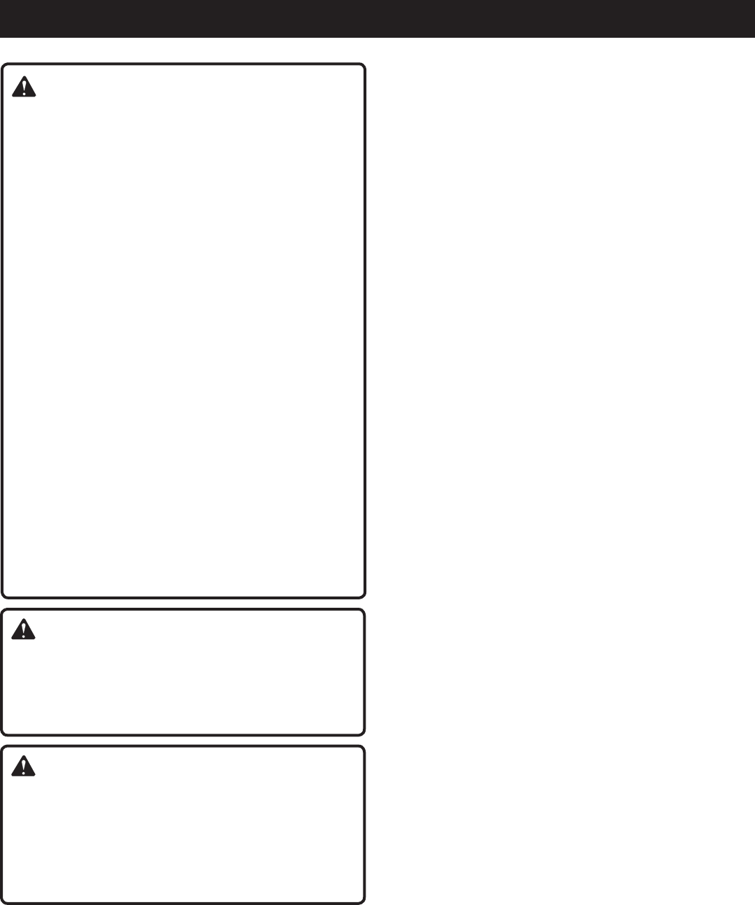
3 — Français
INSTRUCTIONS IMPORTANTES CONCERNANT LA SÉCURITÉ
DANGER :
Monoxyde de Carbone. Utiliser une génératrice à l’intérieur
d’un bâtiment CAUSERA LA MORT EN QUELQUES
MINUTES.
Le tuyau d’échappement de la génératrice contient un
niveauélevédemonoxydedecarbone(CO),lequels’avère
êtreungazpoisoninodoreetinvisible.Sivouspouvezsentir
lesgazdu tuyaud’échappementde la génératrice,vous
respirezduCO.Mais,mêmesivousnepouvezpassentir
lesgazprovenantdutuyaud’échappement,vouspourriez
êtreentrainderespirerduCO.
Nejamais utiliserunegénératrice àl’intérieurd’une
maison, des garages, des petits espaces, ou autres
aires restreintes partiellement fermées. Des niveaux
mortelsdemonoxydedecarbonepeuvents’accumuler
dans ces aires restreintes. Utiliser un ventilateur ou
ouvrirunefenêtreoulesportesNEfourniePASassez
d’air frais à respirer.
UtilisezSEULEMENTlagénératriceàl’extérieuretloin
des fenêtres ouvertes, des portes ouvertes, et des
bouchesd’aérations.Cesouverturespeuventtirerl’air
provenantdutuyaud’échappement.
Mêmesivousutilisezunegénératricecorrectement,desgaz
COpeuventtoujourss’infiltrerdanslamaison.TOUJOURS
utiliserunealarmedemonoxydedecarboneàpilesdans
votre maison.
Si vous ressentez que vous commencez à être étourdi
oufaiblesuiteaufonctionnementdelagénératrice,allez
prendrel’airfraisIMMÉDIATEMENT.Consultezunmédecin.
Vouspourriezavoirunempoisonnementaumonoxydede
carbone.
AVERTISSEMENT :
Lire et comprendre toutes les instructions. Le non-respect
de toutes les instructions ci-dessous peut entraîner une
électrocution, un incendie et/ou un empoisonnement au
monoxyde de carbone, pouvant causer des blessures
graves, voire mortelles.
AVERTISSEMENT :
Lecodeélectriqueaméricain(NationalElectricCode)requiert
que le générateur soit mis à la terre par l’intermédiaire d’une
source de terre approuvée. Avant d’utiliser la borne de
terre, consulter un électricien qualifié, un inspecteur en
électricité ou un organisme local connaissant les codes et
lesréglementslocauxapplicablesàl’utilisationprévuedu
générateur.
CONSERVER CES INSTRUCTIONS
Ce manuel relate à propos d’instructions importantes lesquelles
devraient être suivies pendant l’installation et l’entretien des
piles et de la génératrice.
Nepasbrancheraucircuitélectriqued’unbâtimentàmoins
que la génératrice et le commutateur de transfert n’aient été
installés correctement par un électricien qualifié, et que ce
dernier n’ait vérifié la sortie électrique.
Nepaslaisserdesenfantsoupersonnesn’ayantpasreçu
une formation adéquate utiliser cette unité.
Nejamaismettreenmarcheoufairetournerlemoteurdans
une zone fermée ou partiellement fermée. L’inhalation des
fumées d’échappement provoquent le décès.
Toujours porter une protection oculaire munie d’écrans
latéraux certifiée conforme à la norme ANSI Z87.1, ainsi
qu’une protection auditive lors de l’utilisation de cet outil.
Garderlesbadauds,enfantsetanimauxdomestiquesàune
distance minimum de 3 m (10 pi).
Porterdeschaussuresoudesbottesrobustesetsèches.
Nepasutiliserpiedsnus.
Nepasutiliserlegénérateurenétatdefatigue,sil’onest
souffrant ou sous l’influence de l’alcool, de drogues ou de
médicaments.
Garder toutes les parties du corps à l’écart des pièces en
mouvementetdespartiesbrûlantesdel’outil.
Nepastoucherlesprisesoulesfilsdénudés.
Nepasutiliserlegénérateuravecdescordonsélectriques
usés, effilochés, dénudés ou autrement endommagés.
Avant d’entreposer l’unité pendant une période prolongée,
laisserlemoteurrefroidir,etvidangerlecarburant.
Nepasutiliserlegénérateurdanslapluieoulaneige.
Remiserlagénératricedansunendroitbienventiléaprès
avoir vider le réservoire de carburant. Ne pas remiser le
carburantàproximitédelagénératrice.
Pour le transport dans un véhicule, le réservoir doit être vide,
lerobinetdecarburantferméetlamachinebienarrimée.
Laisser le moteur refroidir pendant 5 minutes avant de faire
le plein.
Manipulerlecarburantavecprécautionpouréviterlesrisques
d’incendiesetdebrûlures.Lecarburantestextrêmement
inflammable.
Nepasfumerpendantlamanipulationducarburant.
Conserverlecarburantdansunbidonoujerricanapprouvé
pour l’essence.
Poser la machine sur un sol plat, arrêter le moteur et le laisser
refroidir avant de faire le plein.
Desserrerlebouchonduréservoirlentementpourrelâcher
lapressionetéviterquelecarburantnes’échappe.
Unefoisleréservoirplein,remettrelebouchonenplaceet
le serrer fermement.
Essuyertoutlecarburantéventuellementrépandu.
N’essayerenaucuncasdebrûlerlecarburantrépandu.
Une vibration est normale pendant l’utilisation de la
génératrice. Pendant et après l’utilisation de la génératrice,
inspectezcelle-ci,toutcommelescâblesd’extensionetles
câblesbranchésàlaboîted’alimentationafindedétecter
toutbrispotentieldumatériel.Faitesréparertoutdommage
immédiatement ou remplacer les pièces endommagées au
besoin. Ne pas utiliser de fiches ou des câbles qui sont

4 — Français
INSTRUCTIONS IMPORTANTES CONCERNANT LA SÉCURITÉ
RÈGLES DE SÉCURITÉ PARTICULIÈRES
endommagés tels qu’ils aient des signes de fissures ou
si la couche isolante est craquée ou si les lamelles sont
endommagées.
Il est préférable d’utiliser une génératrice fixe comme
source d’énergie de secours pour alimenter la maison en
cas de panne d’électricité. Une génératrice portative, même
correctement branchée, risque une surcharge. Il peut en
résulter une surchauffe ou une contrainte indue sur les
composantes du génératrice, ce qui peut provoquer une
défaillance de la génératrice.
Utiliser uniquement des pièces de rechange et des
accessoires approuvés et suivre les instructions dans la
section Entretien de ce manuel. L’usage de pièces non
autorisées ou le non-respect des instructions peut présenter
desrisquesdechocélectriqueoudeblessures.
Entretenir le produit conformément aux instructions de ce
manuel d’utilisation.
Inspecter le produit avant chaque utilisation pour s’assurer
qu’iln’yapasdepiècesdesserrées,defuitesdecarburant,
etc. Remplacer les pièces endommagées.
AVERTISSEMENT :
Lorsque cette génératrice est utilisée pour fournir
de l’énergie à un système électrique d’un bâtiment :
cette génératrice doit être installée par un électricien
qualifiéetdoitêtrebranchéeàuncircuitfermémunid’un
interrupteurdetransfert,conformémentauCodeNational
ÉlectriqueNFPA70.Lagénératricedevraêtrebranchéesur
un interrupteur de transfert lequel pourra allumer tous les
conducteurs autres que celui du circuit électrique principal.
Le cadre de la génératrice doit être mis à la terre par
l’intermédiaire d’une source de terre approuvée. Si cette
étape n’est pas faite, la génératrice ne sera pas isolée du
circuit électrique et cela pourrait entraîner des blessures
graves, voire même la mort chez un électricien travaillant
pour l’usine.
NEPASutilisercettegénératricepouralimenterlesappareils
d’urgence médicale ou le matériel de survie.
L’échappement contient du monoxyde de carbone, un
gaz toxique incolore et inodore. L’inhalation des fumées
d’échappement peut causer la perte de conscience et
le décès. Si la machine tourne dans un endroit clos ou
partiellement clos, l’air peut contenir une quantité dangereuse
de monoxyde de carbone. Pour éviter l’accumulation de
fumées d’échappement, toujours assurer une ventilation
adéquate.
Toujours utiliser un détecteur de monoxyde de carbone
fonctionnant sur piles lors de l’utilisation du générateur.
En cas de sensation de nausée, d’étourdissement ou de
faiblesselorsdel’utilisationdugénérateur,l’arrêteretaller
immédiatement à l’air frais. Consulter un docteur. Il peut
s’agird’unempoisonnementaumonoxydedecarbone.
Placerlegénérateursurunesurfacestableetplatesurune
pente dont l’inclinaison ne dépasse pas 4°.
Utiliserdansunendroitbienventiléetbienéclairéàl’écart
des zones de travail pour éviter les interférences sonores.
L’utilisation du générateur dans des conditions mouillées
peut entraîner l’électrocution. Conserver l’unité au sec.
Garderlegénérateuràaumoins1m(3pieds)detouttype
dematériaucombustible.
Nejamaisutiliserlegénérateurprèsdematériauxdangereux.
Nepasutiliserlegénérateurprèsd’unestationdedistribution
d’essence ou de gaz naturel.
Ne pas toucher le silencieux ou le cylindre durant ou
immédiatement après l’utilisation. Ils sont BRÛLANTS et
peuventprovoquerdesbrûlures.
Cette génératrice est équipée d’un connecteur neutre
libre.Celasignifiequeleconducteurneutren’estpasrelié
électriquement au cadre.
Ne pas laisser le réservoir d’essence de la génératrice
déborderlorsduremplissage.Remplirleréservoirjusqu’à
25,4 mm (1 po) de l’ouverture du goulot du réservoir pour
permettrel’expansionducarburant.
Nepasfumerlorsduremplissagedugénérateuravecde
l’essence.
Fermer le moteur et le laisser refroidir complètement avant
l’ajoutdecarburantoulalubrificationdelagénératrice.
Nepasretirerlajauged’huileoulebouchonduréservoirde
carburantlorsquelemoteurtourne.
Bientenircomptedetouslesautocollantsdesécuritésitués
sur le générateur.
Garder les enfants à un minimum de 3 m (10 pieds) du
générateur à tout moment.
L’unité fonctionne le mieux à des températures comprises
entre -5 et 40 °C (23 et 104 °F) avec une humidité relative
de 90 % ou moins.
Des modifications spéciales pour une performance en
haute altitude sont requises si le générateur est utilisé en
permanence à des altitudes supérieures à 1 524 m (5 000
pieds). Contacter le centre de réparations agréé le plus
proche pour plus d’informations et pour faire effectuer des
modifications.
Vérifierlatensionetlafréquencerequisesavantdebrancher
tout équipement électronique sur le générateur. Le générateur
peutsetrouverendommagésilesappareilsbranchésne
sont pas prévus pour fonctionner à une tension égale à ±
10% et une fréquence égale à ± 3 hz de celles indiquées
sur la plaque signalétique du générateur.
Conserver ces instructions. Les consulter fréquemment et les
utiliserpourinstruirelesautresutilisateurséventuels.Sice
produit est prêté, il doit être accompagné de ces instructions.

5 — Français
SYMBOLES
Lestermesdemiseengardesuivantsetleursignificationontpourbutd’expliquerledegréderisquesassociéàl’utilisation
de ce produit.
SYMBOLE SIGNAL SIGNIFICATION
DANGER : Indique une situation extrêmement dangereuse qui, si elle n’est pas évitée,
aurapourconséquencesdesblessuresgraves,voiremortelles.
AVERTISSEMENT : Indique une situation potentiellement dangereuse qui, si elle n’est pas évitée,
aurapourconséquencesdesblessuresgravesoumortelles.
ATTENTION : Indique une situation potentiellement dangereuse qui, si elle n’est pas évitée,
pourraitentraînerdesblessureslégèresoudegravitémodérée.
ATTENTION : (Sanssymboled’alertedesécurité)Indiqueunesituationpouvantentraîner
des dommages matériels.
Certainsdessymbolesci-dessouspeuventêtreutiliséssurleproduit.Veilleràlesétudieretàapprendreleursignification.
Uneinterprétationcorrectedecessymbolespermettrad’utiliserleproduitplusefficacementetderéduirelesrisques.
SYMBOLE NOM DÉSIGNATION / EXPLICATION
Alerte de sécurité Indiqueunrisquedeblessurepotentiel.
Lire manuel d’utilisation Pourréduirelesrisquesdeblessures,l’utilisateurdoitlireetveillerà
biencomprendrelemanueld’utilisationavantd’utiliserceproduit.
Avertissement concernant
l’humidité Nepasexposeràlapluieoul’humidité.
Choc électrique
Une utilisation de l’équipement dans des conditions non sèches et le
non-respect des méthodes sans danger peuvent entraîner un choc
électrique.
Vapeurs toxiques
Durantle fonctionnement, le générateur émet du monoxyde de
carbone,ungaztoxiqueinodoreetincolore.Respirerlemonoxyde
decarbonepeutentraînerdesnausées,desévanouissements,voire
la mort.
Incendie/explosion
Le carburant et ses vapeurs sont extrêmement inflammables et
explosifs.Unincendieouuneexplosionpeutentraînerdesbrûlures
graves, voire la mort.
Surfacechaude Pouréviterles risques de blessuresou de dommages, éviter tout
contactaveclessurfacesbrûlantes.
Danger au levage Pourréduirelerisquedeblessuresgraves,éviterdeleverlegénérateur
seul.
Miseàlaterre Consulter un électricien local pour déterminer les exigences de mise
à la terre avant le fonctionnement.
Électrocution Une mauvaise mise à la terre du générateur peut causer une
électrocution, surtout si le générateur est équipé d’un kit de roues.
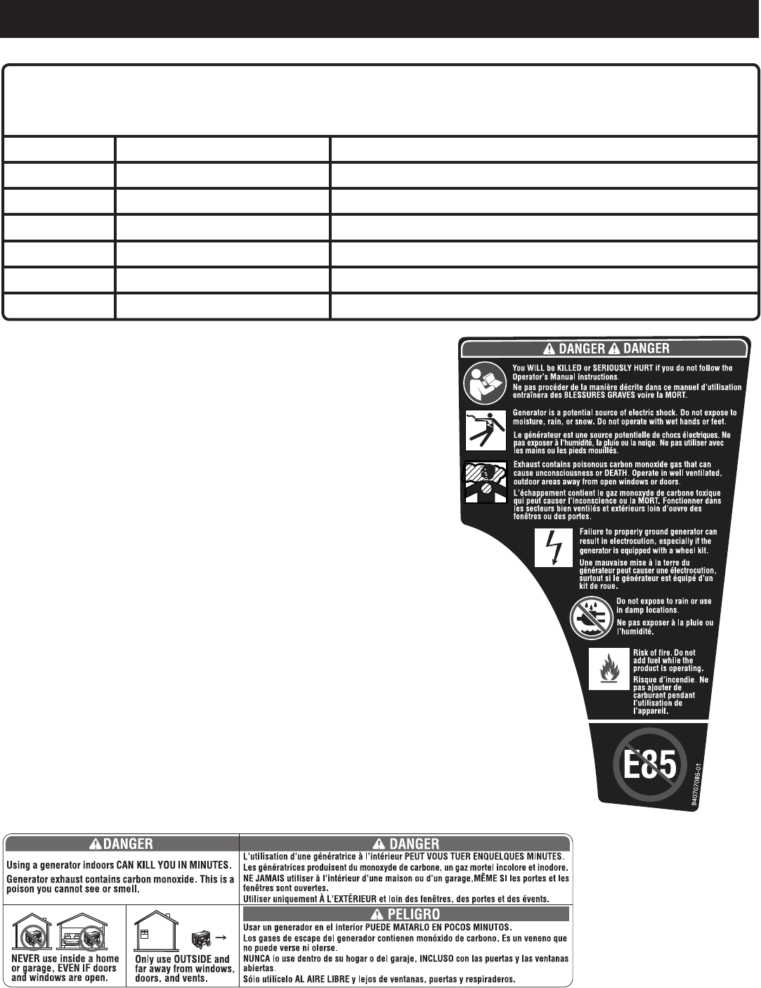
6 — Français
SYMBOLES
AUTOCOLLANTS DE SÉCURITÉ
Les informations ci-dessous se trouvent sur le générateur. Pour des raisons
de sécurité, étudier et comprendre tous les autocollants avant de mettre le
générateur en marche.
Siunautocollantsedétacheoudevientillisible,contacterlecentrederépa-
rationsagréépourobtenirunautocollantderechange.
Ne pas procéder de la manière décrite dans ce manuel d’utilisation
entraîneradesBLESSURESGRAVESvoirelaMORT.
Risqued’incendie.Nepasajouterdecarburantpendantl’utilisationde
l’appareil.
Legénérateurestunesourcepotentielledechocsélectriques.Nepas
exposeràl’humidité,lapluieoulaneige.Nepasutiliaveclesmainsoules
pieds mouillés.
L’échappement contient le gaz monoxyde de carbone toxique qui peut causer
l’inconscienceoulaMORTlessecteursbienventilésetextérieursloind’ouvredesfenêt
ou des portes.
Une mauvaise mise à la terre du générateur peut causer une électrocution, surtout si le
générateur est équipé d’un kit de roue.
Nepasexposeràlapluieoul’humidité.
L’utilisationd’unegénératriceàl’intérieurPEUTVOUSTUERENQUELQUESMINUTES.Les
génératricesproduisentdumonoxydedecarbone,ungazmortelincoloreetinodore.
NEJAMAISutiliseràl’intérieurd’unemaisonoud’ungarage,MêMESIlesportesetlesfenêtres
sont ouvertes.
UtiliseruniquementÀL’EXTÉRIEURetloindesfenêtres,desportesetdesévents.
NepasutiliserlecarburantE85.
Certainsdessymbolesci-dessouspeuventêtreutiliséssurleproduit.Veilleràlesétudieretàapprendreleursignification.
Uneinterprétationcorrectedecessymbolespermettrad’utiliserleproduitplusefficacementetderéduirelesrisques.
SYMBOLE NOM DÉSIGNATION / EXPLICATION
VVolts Tension
AAmpères Courant
Hz Hertz Fréquence(cyclesparseconde)
WWatt Puissance
hrs Heures Durée
gal Gallon Volume
qt Quart Volume
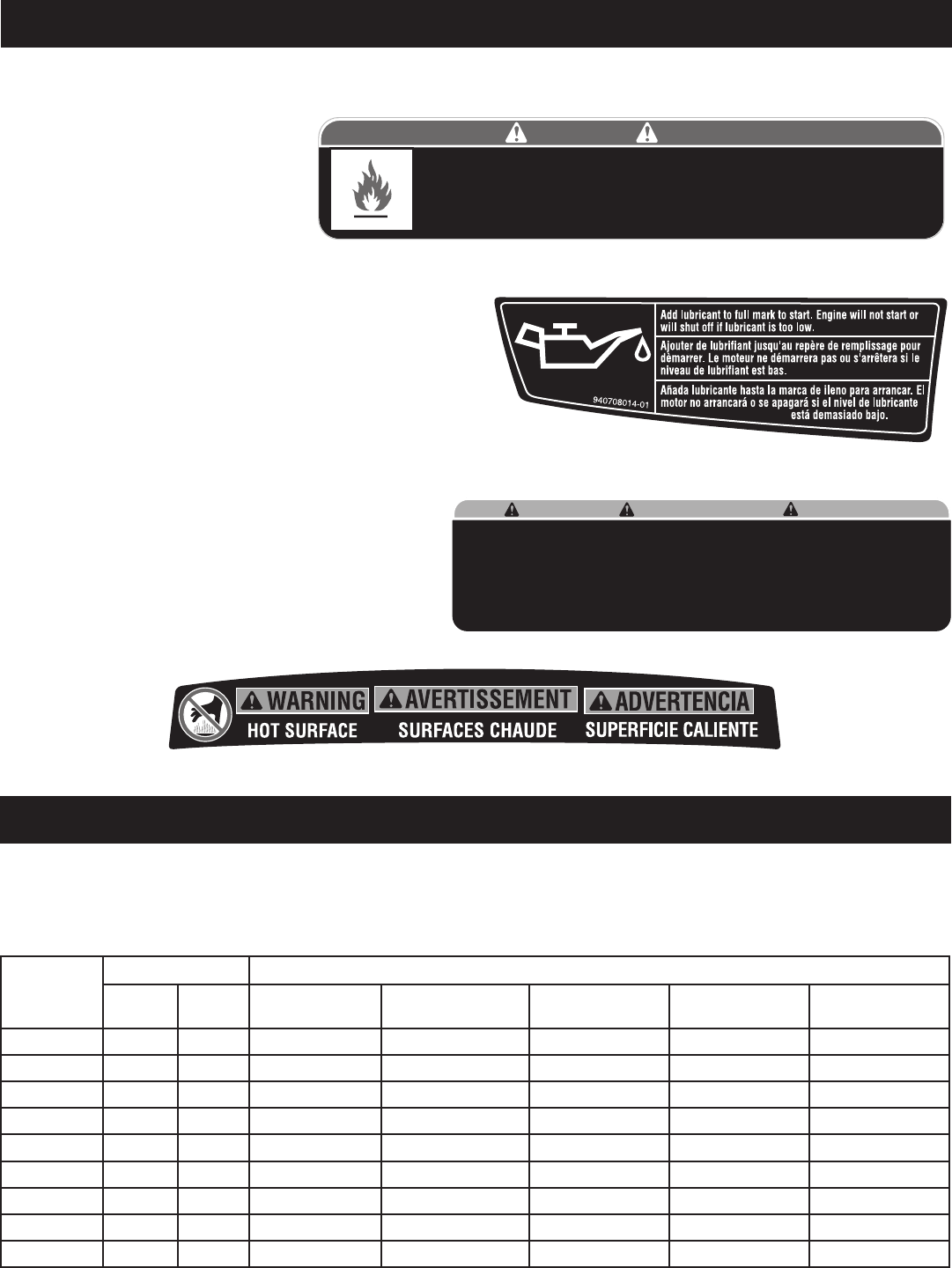
7 — Français
SYMBOLES
AVERTISSEMENT CONCERNANT LE CARBURANT
Nepasfumerlorsduplein.Nepastrop
remplir.Lepleinestobtenuà25,4mm
(1 po) en dessous du haut du goulot de
remplissage. Arrêter le moteur pendant
cinq minutes avant de faire le plein
pour éviter que la chaleur du silencieux
n’allumelesvapeursdecarburant.
AVERTISSEMENT CONCERNANT LE LUBRIFIANT MOTEUR
Ajouterdelelubrifiantavantl’utilisationinitialedugénérateur.La
contenance du réservoir est de 0,39 l (0,42 quarts). Toujours vérifier
leniveaudelubrifiantavantchaqueutilisation.Leniveaudelubrifiant
doit toujours se trouver dans la zone hachurée de la jauge. Cette
unité est équipée d’un capteur d’huile qui coupe automatiquement
lemoteursileniveaudelubrifiantdescendàunniveaudangereux.
MISE À LA TERRE - AVERTISSEMENT
Lecodeélectriqueaméricain(NationalElectricCode)requiertquelegénérateursoitmisàlaterrepar
l’intermédiaire d’une source de terre approuvée.
AVERTISSEMENT CONCERNANT LES SURFACES
BRÛLANTES
Nepastoucherlesilencieuxoulecylindreenaluminium
du moteur. Ils sont BRÛLANTS et peuvent causer de
gravesbrûlures.Nemettreaucunmatériauinflammable
oucombustiblesurlechemindirectdel’échappement.
Product does not include ground rod or copper wire. National Electric Code requires generator to be
properly grounded to an approved earth ground. Call an electrician for local grounding requirements.
Le produit ne comprend pas de piquet de terre ou de fil en cuivre. Le code electrique americain (National
Electric Code) requiert un générateur pour une bonne mise à la terre approuvée. Appeler un électricien
pour connaître les exigences locales de mise à la terre.
El producto no incluye el alambre de cobre ni la barra de conexión a tierra. Los Reglamentos Nacionales
de Electricidad exigen que el generador esté debidamente conectado a una tierra aprobada.
Comuniquese con un electrista para todo lo relacionado con los requistos de conexión a tierra.
WARNING ADVERTENCIA
AVERTISSEMENT
940513008-02
CARACTÉRISTIQUES ÉLECTRIQUES
TAILLE DU CÂBLE DU CORDON PROLONGATEUR
Voirletableauci-dessouspourvérifierquelatailledecâbledescordonsprolongateursutilisésestcapabledeporterlacharge
requise.Destaillesdecâblesinadéquatespeuventcauserunechutedetensionquipeutdétériorationsl’appareiletsurchauffer
le cordon.
Courant en
ampères
Charge en watts Longueur de cordon permise maximum
À 120 V À 240 V Fil de
calibre 8 Fil de
calibre 10 Fil de
calibre 12 Fil de
calibre 14 Fil de
calibre 16
2,5 300 600 305 m (1 000 pieds) 183 m (600 pieds) 114 m (375 pieds) 76 m (250 pieds)
5 600 1 200 152 m (500 pieds) 91 m (300 pieds) 61 m (200 pieds) 38 m (125 pieds)
7,5 900 1 800 107 m (350 pieds) 61 m (200 pieds) 38 m (125 pieds) 31 m (100 pieds)
10 1 200 2 400 76 m (250 pieds) 46 m (150 pieds) 31 m (100 pieds) 15 m (50 pieds)
15 1 800 3 600 46 m (150 pieds) 31 m (100 pieds) 20 m (65 pieds)
20 2 400 4 800 53 m (175 pieds) 38 m (125 pieds) 23 m (75 pieds)
25 3 000 6 000 46 m (150 pieds) 31 m (100 pieds)
30 3 600 7 200 38 m (125 pieds) 20 m (65 pieds)
40 4 800 9 600 27 m (90 pieds)
Risk of Fire. Check for any fuel overflow or leaking. Stop the engine before refueling.
DANGER PELIGRO
Risque d’incendie. Vérifier l'absence de débordement ou de fuite de carburant.
Arrêter le moteur avant de fair le plein.
Riesgo de incendio. Revise si hay algún derrame o fuga de combustible. Apague el
motor antes de poner combustible. 940974007-03
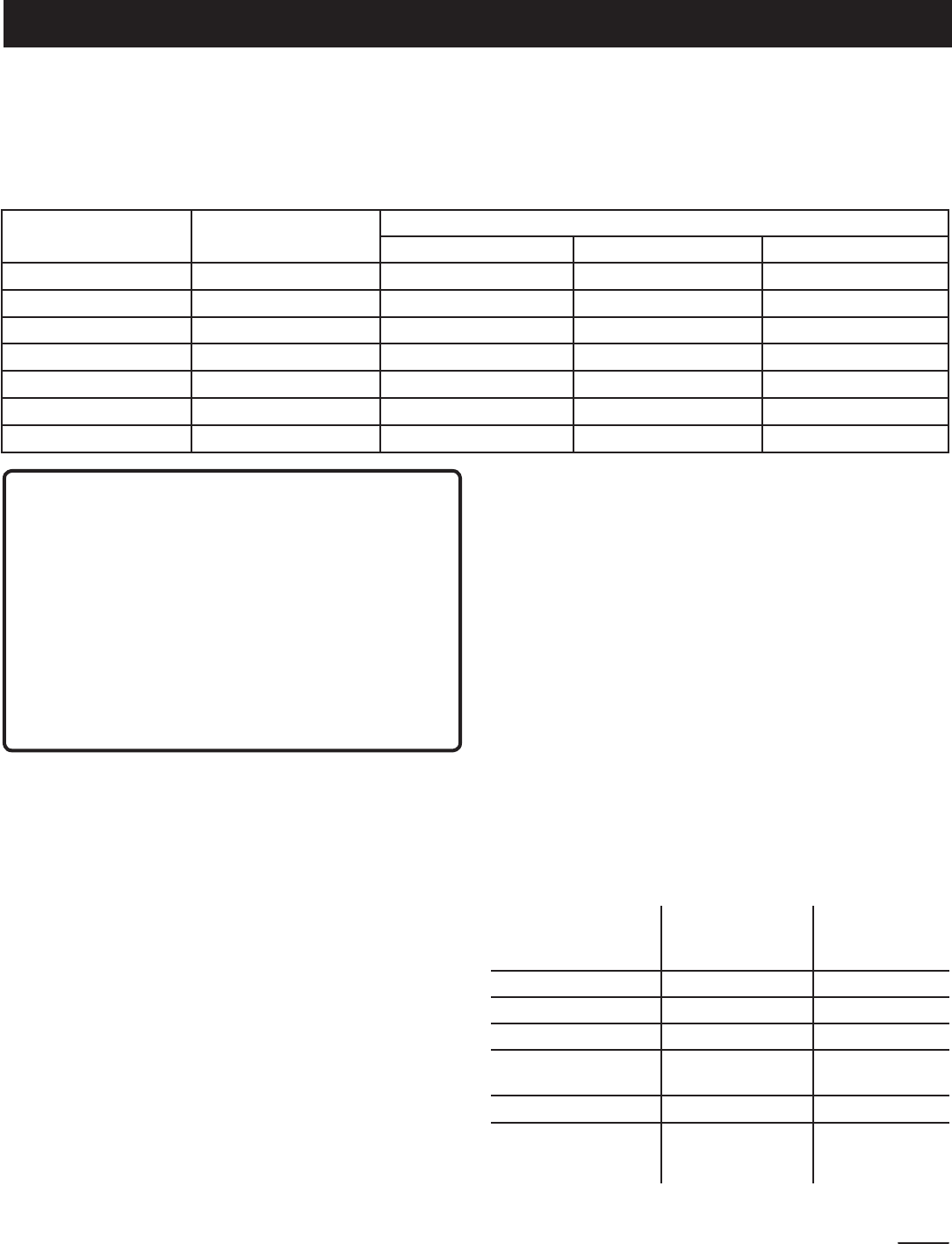
8 — Français
CHARGES DU MOTEUR ÉLECTRIQUE
Les moteurs électriques courants en fonctionnement normal tirent jusqu’à six fois leur courant de fonctionnement lors du démarrage.
Cetableaupeutêtreutilisépourestimerleswattsrequispourdémarrerlesmoteursélectriques«codeG»;cependant,siun
moteur électrique ne démarre pas ou n’atteint pas sa vitesse de fonctionnement, éteindre immédiatement l’appareil ou l’outil
pour éviter d’endommager l’équipement. Toujours vérifier les exigences de l’outil ou de l’appareil utilisé par rapport à la sortie
nominale du générateur.
Taille du moteur (ch) Watts de
fonctionnement
Watts requis pour le démarrage du moteur
Répulsion Induction Condensateur Phase auxiliaire
1/8 275 600 850 1 200
1/6 275 600 850 2 050
1/4 400 850 1 050 2 400
1/3 450 975 1 350 2 700
1/2 600 1 300 1 800 3 600
3/4 850 1 900 2 600 —
1 1 100 2 500 3 300 —
ATTENTION :
Vérifierlatensionetlafréquencerequisesavantdebrancher
tout équipement électronique sur le générateur. Le générateur
peutsetrouverendommagésilesappareilsbranchésnesont
pas prévus pour fonctionner à une tension égale à ± 10%
et une fréquence égale à ± 3 hz de celles indiquées sur la
plaque signalétique du générateur. Pour éviter tout dommage,
toujoursbrancherunechargeadditionnellesurlegénérateur
lorsqu’un appareil à circuits intégrés (tel qu’un téléviseur)
est utilisé. Une varistance peut être aussi nécessaire pour
certaines applications, dans le cas d’un ordinateur, par
exemple. Une varistance peut être aussi nécessaire pour
certaines applications de l’équipement en solide.
CARACTÉRISTIQUES ÉLECTRIQUES
DISJONCTEUR DE FUITE À LA TERRE
Voir la figure 1.
Les prises de 20 A, 120 V sur le générateur sont protégées par
un disjoncteur de fuite à la terre qui protège des dangers de
courants de défaut à la terre. Un exemple de courant de défaut
à la terre est le courant qui passerait par une personne utilisant
un appareil dont l’isolation serait défectueuse, et qui serait en
même temps en contact avec une mise électrique à la terre,
tellequ’undispositifdeplomberie,unsolmouilléoulaterre.
Les prises protégées par un disjoncteur de fuite à la terre ne protègent
pas des court-circuits, des surcharges et des chocs électriques.
Les prises protégées par un disjoncteur de fuite à la terre
peuventêtretestéesaumoyendesboutonsTESTetRESET
(Réinitialisation).
Pour tester :
AppuyersurleboutonTEST.Cecidoitfairesortirlebouton
Reset (Réinitialiser).
Pourrestaurerl’alimentation,appuyersurleboutonRESET
(Réinitialiser).
Effectuer ce test chaque mois pour assurer un bon
fonctionnementdudisjoncteurdefuiteàlaterre.Silegénérateur
est remisé à l’extérieur, non protégé des intempéries, tester la
prise du disjoncteur avant chaque utilisation.
CAPACITÉ DU GÉNÉRATEUR
S’assurerque le générateur peut fournirleswattscontinus
(de fonctionnement) et de surtension (démarrage) suffisants
pourtouslesarticlesalimentésaumêmemoment.Suivreces
simples étapes.
1. Sélectionner les articles qui seront alimentés au même
moment.
2. Faireletotaldeswattscontinus(defonctionnement)deces
articles. Ceci correspond à la somme de puissance que
le générateur doit produire pour que ces articles puissent
fonctionner.Voirletableauderéférencedewattageàdroite.
3. Déterminerleswattsdesurtension(démarrage)nécessaires.
Leswattsdesurtensioncorrespondentàlacourtepointe
de puissance nécessaire pour démarrer les outils ou les
appareils à moteur électriques, tels que les scies circulaires
ou les réfrigérateurs. Les moteurs ne démarrant pas tous au
mêmemoment,letotaldeswattsdesurtensionpeutêtre
déterminéenajoutantuniquementlesarticlesauwattagede
surtensionsupplémentaireleplusélevéauwattagenominal
total de l’étape 2.
Exemple :
Outilouappareil
Watts de
fonctionnement
(continu)
Watts de
surtension
(démarrage)
Réfrigérateur 700 1 350
Ventilateur portatif 40 120
Ordinateurportable 250 250
Téléviseur à écran plat
de 116,8 cm (46 po)
190 190
Lampes (75 Watts) 75 75
1 255 Wattage de
fonctionnement
total
1 350 Wattage
de surtension
maximum
Wattage continu (fonctionnement) total 1 255
Pluswattagedesurtensionsupplémentairemaximum +1350
Égalàlasortietotaledugénérateurrequise 2605
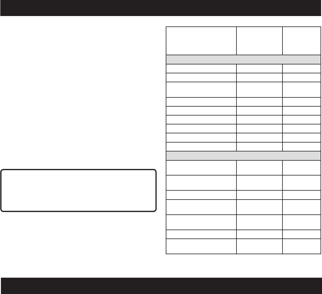
9 — Français
CARACTÉRISTIQUES ÉLECTRIQUES
GESTION DE L’ÉNERGIE
Pour prolonger la durée de vie du générateur et des appareils
reliés, il est important d’effectuer l’ajout de charges électriques
supplémentaires au générateur avec soin. Rien ne doit être
connecté aux sorties du générateur avant le démarrage du
moteur. Une gestion correcte et en toute sécurité de l’énergie
du générateur consiste à ajouter des charges en séquence :
1. Sansappareilconnectéaugénérateur,mettrelemoteuren
marche de la façon décrite dans ce manuel.
2. Brancher et mettre en marche la première charge, de
préférence la plus importante.
3. Laisserlasortiedugénérateursestabiliser(lemoteurtourne
régulièrement et l’appareil relié fonctionne correctement).
4. Brancheretmettrelachargesuivanteenmarche.
5. Unefoisdeplus,laisserlegénérateursestabiliser.
6. Répéter les étapes 4 et 5 pour chaque charge supplémentaire.
Ne jamais ajouter de charges supérieures à la capacité du
générateur.Bienveilleràconsidérerleschargesdesurtension
comme décrit précédemment.
ATTENTION :
Nepassurchargerlacapacitédugénérateur.Ledépassement
delacapacitéduwattage/del’ampéragedugénérateurpeut
endommager le générateur et/ou les appareils électriques
qui lui sont reliés.
Application/Equipo Watts de
fonctionnement
estimé*
Watts
démarrage
estimé*
Urgence / à la maison de secours
Lampes (qté. 4 x 75 W) 300 300
Réfrigérateur 700 1350
Téléviseur à écran plat de
116,8 cm (46 po)
190 190
Récepteur satellite 250 250
Ventilateur portatif 40 120
Radiateur 1300 1300
Ordinateurportable 250 250
Mijoteuse 270 270
Radio 50 50
Site de travail
Perceuseélectrique−3/8
ch 600 1000
Lampe de travail quartz-
halogène 1000 1000
Sciealternative 960 1920
Sciecirculaire−184mm
(7-1/4 po) 1400 2300
Scieàonglet−254mm
(10 po) 1800 1800
Compresseur à air - 1/4 ch 970 1600
Pulvérisateursansair−
1/3 ch 600 1200
*Leswattagesindiquéssontapproximatifs.Vérifierlewattagesur
l’outil ou l’appareil.
CARACTÉRISTIQUES
FICHE TECHNIQUE
MOTEUR
Typedemoteur.......................... Arbreàcamesentêtesimple
Course x alésage ............................................ 88 mm x 64 mm
Systèmederefroidissement ........................................Air forcé
Taux de compression ....................................................... 8.5:1
Systèmededémarrage ...............................................À rappel
Systèmed’allumage ......................................................... T.C.I.
Bougie ...........................................................NHSPLDA7RTC
Volumedelubrifiantmoteur ........................0,39 l (0,42 quarts)
Volumedecarburant ..........................................3,79 l (1,0 gal)
GÉNÉRATEUR
Tension nominale ......................................... 120 V AC/12 V DC
Ampérage nominal ................................... 13,33A AC/7,5A DC
Watts de fonctionnement ............................................ 1 600 W
Watts requis au démarrage ......................................... 2 000 W
Fréquence nominale ........................................................ 60 Hz

10 — Français
CARACTÉRISTIQUES
BIEN CONNAÎTRE LE GÉNÉRATEUR
Voir la figure 2.
L’utilisationsûredeceproduitexigeunecompréhensiondes
renseignements figurant sur le produit et contenus dans le
manueld’utilisation,ainsiqu’unebonneconnaissancedu
projet entrepris. Avant d’utiliser ce produit, se familiariser
avec toutes ses caractéristiques et règles de sécurité.
PRISES DE 120 V C.A.
La génératrice comprend deux prises monophasées de
60 Hz, 120 V c.a., 20 A protégées par un disjoncteur de fuite
de terre. Elles peuvent être utilisées pour le fonctionnement
d’appareils, d’éclairage électrique, d’outils et de charges de
moteur adéquats.
FILTRE À AIR
Les filtre à air permet de limiter la quantité de poussière et
de saleté pénétrant dans l’unité lors du fonctionnement.
MODE DE MARCHE AU RALENTI AUTOMATIQUE
L’interrupteur de mode de marche au ralenti automatique
est utilisé pour contrôler la vitesse du moteur et économiser
lecarburant.Lorsquel’interrupteurestrégléàlaposition«
ON » (I) (marche) et qu’aucun appareil n’est relié à l’unité, le
moteurpasseaumodederalenti.Siunappareilestajouté,
lavitessedumoteuraugmentepourlefairefonctionner.Si
l’appareil est retiré, le moteur revient au mode de ralenti.
CÂBLE POUR CHARGER LES PILES
Utiliserlecâblepourchargerlespilespourfixerpilesplomb-
acide de 12 V à la génératrice.
NOTE :Utiliseruniquementuncâbledestinéàchargerles
pilesauplomb-acidehumidesexposéesàl’airelibre.
POIGNÉE DE TRANSPORT
La génératrice comprend une poignée pour faciliter le
transport.
D’ÉTRANGLEMENT
Le d’étranglement sert lors du démarrage le moteur est froid.
DISJONCTEUR C.C.
Le disjoncteur est fourni pour protéger le générateur contre
les surcharges électriques.
PRISE DE 12 V C.C.
Votre génératrice est dotée d’une prise 12 V, 7,5 A c.c. pour
lechargementdepilesplomb-acide.
AVERTISSEMENT :
La prise de 12 V c.c. est conçue pour charger les piles au
plomb-acidehumidesexposéesàl’airelibreseulement.
Lesautrestypesdepilespeuventéclateretcauserdes
blessuresetdesdommages.
COMMUTATEUR MARCHE/ARRÊT
Lecommutateurmarche/arrêtestutilisédanslacombinaison
avec le manchon en lanceur à rappel pour commencer le
moteur. Il est aussi utilisé pour arrêt le moteur.
RÉSERVOIR DE CARBURANT
Leréservoirdecarburantaunecontenancede3,79l(1,0gal)
NOTE : Le carburant estacheminédu réservoir au
carburateur uniquement lorsque l’interrupteur « On/Off »
(marche/arrêt) est réglé à la position « ON » (I) (marche).
BORNE DE TERRE
La borne de terre permet d’obtenir une bonne mise à la
terre du générateur pour la protection contre les chocs
électriques. Consulter un électricien local pour les exigences
de mise à la terre locales.
AFFICHAGE DÉL
Les DÉL indiquent si la génératrice est utilisée ou en
surcharge, ou s’il faut lui ajouter de l’huile.
BOUCHON/JAUGE D’HUILE
Retirerlebouchonderemplissaged’huilepour vérifierle
niveaud’huileetfairel’appointselonlebesoin.
POIGNÉE RÉTRACTABLE
Lagénératricecomprendunepoignéerétractablequipeut
être ajustée aux fins d’entreposage et de transport.
LANCEUR À RAPPEL
La lanceur à rappel est utilisée (avec le commutateur marche/
arrêt) pour mettre le générateur du moteur en marche.
BOUCHON DE CARBURANT VENTILÉ
Lagénératriceestmunied’unbouchondecarburantdoté
d’un évent d’aération qui peut être ouvert ou fermé. Lors d’un
fonctionnement normal, l’évent doit demeurer en position
ouverte.
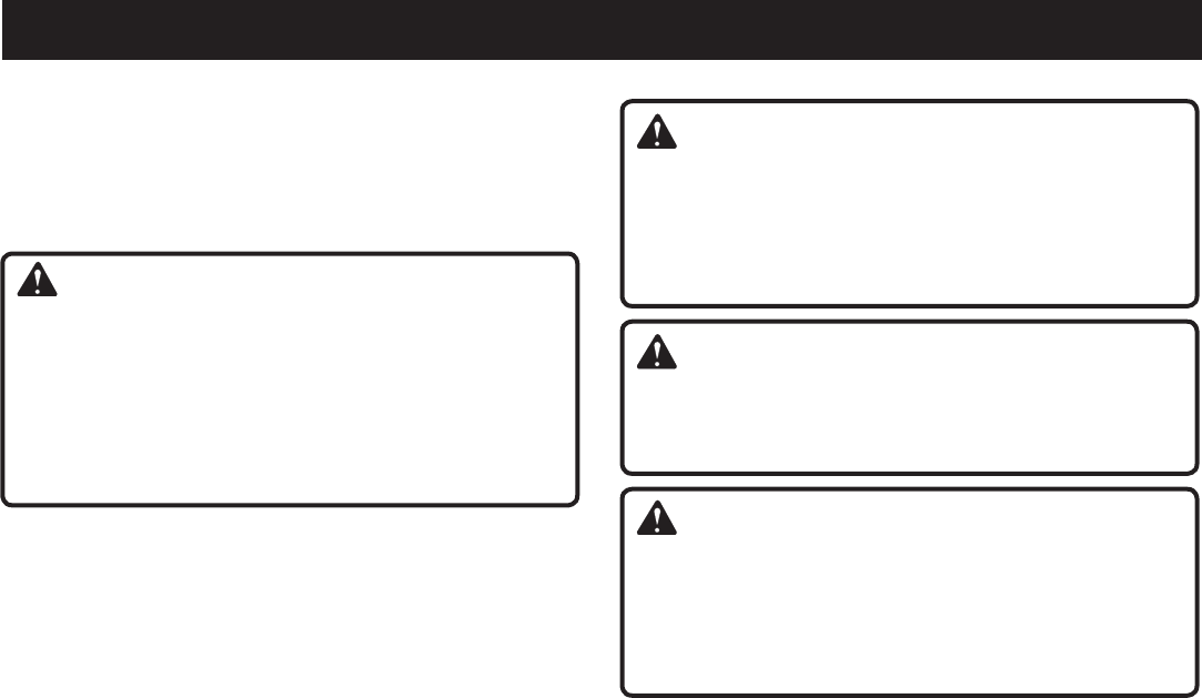
11 — Français
ASSEMBLAGE
DÉBALLAGE
Ceproduitaétéexpédiécomplètementassemblé.
Avec précaution, sortir l’outil et les accessoires de la
boîte.S’assurerquetouteslespiècesfigurantsurlaliste
de contrôle sont incluses.
AVERTISSEMENT :
Ne pas utiliser le produit si, en le déballant, vous
constatez que des éléments figurant dans la liste des
piècesdétachéessontdéjàassemblés.Certainespièces
figurantsurcettelisten’ontpasétéassembléesparle
fabricantetexigentuneinstallation.Lefaitd’utiliserun
produit qui a été assemblé de façon inadéquate peut
entraînerdesblessures.
Examiner soigneusement l’unité pour s’assurer que rien
n’aétébriséouendommagéencoursdetransport.
Ne pas jeter les matériaux d’emballage avant d’avoir
soigneusement examiné le produit et vérifié qu’il
fonctionne correctement.
Sidespiècesmanquentousontendommagées,appeler
le1-800-860-4050pourobtenirdel’aide.
LISTE DE CONTRÔLE D’EXPÉDITION
Générateur
Câblepourchargerlespiles
Lubrifiantdemoteur(SAE10W30)
Poignée de clé
Cléàbougie
Manueldel’utilisateur
AVERTISSEMENT :
Sidespiècesmanquentousontendommagées,nepas
utiliser ce produit avant qu’elles aient été remplacées.
Le fait d’utiliser ce produit même s’il contient des pièces
endommagées ou s’il lui manque des pièces peut
entraînerdesblessuresgraves.
AVERTISSEMENT :
Ne pas tenter d’utiliser le générateur avant d’avoir
terminél’assemblage.Lenon-respectdecetteinstruction
pourraitentraînerdesblessuresgraves.
AVERTISSEMENT :
Nepasessayerdemodifierceproduitoudecréerdes
accessoires non recommandés pour ce produit. De
telles altérations ou modifications sont considérées
commeunusageabusifetpeuventcréerdesconditions
dangereusespouvantentraînerdesblessuresgraves.
12 — Français
UTILISATION
DANGER :
Monoxyde de Carbone. Utiliser une génératrice à l’intérieur
d’unbâtimentCAUSERALAMORTENQUELQUESMINUTES.
Le tuyau d’échappement de la génératrice contient un
niveauélevédemonoxydedecarbone(CO),lequels’avère
êtreungazpoisoninodoreetinvisible.Sivouspouvezsentir
lesgazdu tuyau d’échappementdela génératrice, vous
respirezduCO.Mais,mêmesivousnepouvezpassentir
lesgazprovenantdutuyaud’échappement,vouspourriez
êtreentrainderespirerduCO.
Nejamaisutiliserunegénératriceàl’intérieurd’unemai-
son, des garages, des petits espaces, ou autres aires re-
streintes partiellement fermées. Des niveaux mortels de
monoxydedecarbonepeuvents’accumulerdanscesai-
res restreintes. Utiliser un ventilateur ou ouvrir une fenêtre
oulesportesNEfourniePASassezd’airfraisàrespirer.
UtilisezSEULEMENTlagénératriceàl’extérieuretloin
des fenêtres ouvertes, des portes ouvertes, et des
bouchesd’aérations.Cesouverturespeuventtirerl’air
provenantdutuyaud’échappement.
Mêmesivousutilisezunegénératricecorrectement,desgaz
COpeuventtoujourss’infiltrerdanslamaison.TOUJOURS
utiliserunealarmedemonoxydedecarboneàpilesdans
votre maison.
Sivousressentezquevouscommencezàêtreétourdiou
faiblesuiteaufonctionnementdelagénératrice,allezpren-
drel’airfraisIMMÉDIATEMENT.Consultezunmédecin.Vous
pourriezavoirunempoisonnementaumonoxydedecarbone.
DANGER :
Une mauvaise mise à la terre du générateur peut causer
une électrocution, surtout si le générateur est équipé d’un
kitderoues.Lecodeélectriqueaméricain(NationalElectric
Code) requiert un générateur correctement mis à la terre à
une source de terre approuvée. Appeler un électricien pour
connaître les exigences locales de mise à la terre.
AVERTISSEMENT :
La familiarité avec l’appareil ne doit pas faire oublier la
vigilance. Ne pas oublier qu’une fraction de seconde
d’inattentionpeutentraînerdesblessuresgraves.
AVERTISSEMENT :
N’utiliserniaccessoires,nioutilsnonrecommandésparle
fabricantdeceproduit.L’utilisationdepiècesetaccessoires
nonrecommandéspeutentraînerdesblessuresgraves.
APPLICATIONS
Cé générateur est conçu pour fournir une alimentation électrique
pour le fonctionnement d’éclairages, d’appareils, d’outils et de
chargesdemoteurcompatibles.
AVANT D’UTILISER L’UNITÉ
UtiliseruniquementÀL’EXTÉRIEURetloindesfenêtres,des
portes et des évents.
NEJAMAISutiliseràl’intérieurd’unemaisonoud’ungarage,
MêMESIlesportesetlesfenêtressontouvertes.
Toujoursposerlagénératricesurunesurfacestableetplate.
AFFICHAGE DÉL
Voir la figure 3.
Alimentation :
Levoyantd’alimentations’allumelorsquelagénératriceesten
marche et lorsque les prises fonctionnent.
NOTE : Silagénératriceestensurcharge, le voyant
d’alimentation s’éteindra.
Surcharge :
L’indicateur de surcharge s’allume si la puissance et l’intensité
maximalesdelagénératricesontdépassées.Silasurcharge
est minime, l'appareil continuera à fonctionner normalement.
Silasurchargeestplussévère,laprisede120Vs'éteindraafin
de protéger les composants électriques de la génératrice. Pour
réinitialiser la génératrice, éteindre l’unité et retirer toutes les
charges. La génératrice pourra uniquement être réinitialisée si
elle est mise à l’arrêt.
Huile :
L’indicateurdebasniveaud’huileclignoteetlemoteurs’arrête
automatiquementlorsqueleniveaud’huileestbas.Ilnefaut
pas redémarrer le moteur tant qu’une quantité suffisante d’huile
n’aura pas été ajoutée dans la génératrice.
NOTE :Ilestnormalquelesvoyantss’allumentouclignotent
à chaque démarrage du moteur. Après le réchauffement du
moteur,lesvoyantsrespectentlaformeci-dessus.
ATTENTION :
Une tentative de démarrage du moteur avant le remplissage
enlubrifiantcorrectentraîneunepannedel’équipement.
VÉRIFICATION/AJOUT DE LUBRIFIANT
Voir la figure 4.
Lelubrifiantmoteurauneinfluencemajeuresurlaperformance
du moteur et la durée de service. De manière générale et pour
toutestempératures,del’huileSAE10W-30estrecommandée.
Toujours utiliser une huile moteur à 4 temps conforme ou su-
périeureauxexigencesdeserviceSJAPI.
NOTE : Deslubrifiantsmoteur2tempsnondétergentesen-
dommageront le moteur et ne doivent pas être utilisées.
Desserrer la vis située sur le dessus du capot moteur. Retirer
le couvercle et mettre de côté.
Dévisser le capuchon d’huile/la jauge et les retirer.
Essuyerlajaugeetl’insérerdenouveaudansletrousans
visser.
Retirer une nouvelle fois la jauge et vérifier le niveau de
lubrifiant.Leniveaudelubrifiantdoitêtrecomprisentreles
niveaux minimal et maximal indiqués sur la jauge.
Sileniveauestfaible,ajouterdel’huilemoteurjusqu’àce
que le niveau se situe entre les niveaux minimal et maximal
indiqués sur la jauge.
Réinstalleretserrerlebouchond’huile/lajauge.
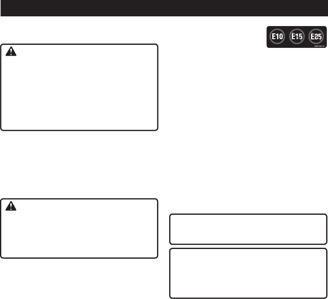
13 — Français
UTILISATION
VÉRIFICATION/AJOUT DE CARBURANT
Voir la figure 5.
AVERTISSEMENT :
L’essenceestextrêmementinflammableetexplosive.Un
incendieouuneexplosiond’essenceinfligeraitdesbrûlures
à l’opérateur et aux autres personnes présentes. Toujours
couperlemoteuravantderemettreducarburant.Nejamais
remplir le réservoir d’une machine lorsque le moteur tourne
ouestchaud.S’éloignerd’aumoins9m(30pi)dupoint
d’approvisionnement avant de lancer le moteur. Ne pas
fumer, et rester à l’écart des flammes vives et des étincelles.
Une mauvaise manipulation de l’essence peut entraîner des
blessuresgraves.
Retirerlebouchonduréservoirdecarburant.
Remplirleréservoirdecarburantà25,4mm(1 po) en
dessousduhautdugoulotduréservoirdecarburant.
Replacerlebouchonetvisserjusqu'àcequ'ils'enclenche.
NOTE : Toujoursutiliserdel’essencesansplombavecunindice
d’octanede86ouplus.Nejamaisutiliserducarburantvieux,
éventéoucontaminéetnepasutiliserdemélangelubrifiant/
carburant.Nepaslaisserlapoussièreoul’eaupénétrerdans
leréservoirdecarburant.Ne pas utiliser le carburant E85.
AVERTISSEMENT :
S’assurerdel’absencedefuitesdecarburant.Unbouchon
decarburantquifuitposeunrisqued’incendieetdoitêtre
remplacé immédiatement. Toutes les fuites doivent être
éliminéesavantd’utiliserleproduit.Nepasprendrecette
précautionpeutcauserunincendie,entraînantdesblessures
graves.
UTILISATION DE STABILISATEUR DE
CARBURANT
Lecarburantdéfraîchit,s’oxydeet se dégrade avec le
temps.L’ajoutdestabilisateurdecarburantallongeladurée
d’utilisationducarburantetpermetd’éviterla formation de
dépôtspouvantobstruerlecircuitde carburant. Suivreles
instructionsdufabricantdestabilisateurdecarburantpourle
rapportstabilisateur/carburantcorrect.
Ajouterlestabilisteur dansleréservoirdecarburantpuis
remplir d’essence en suivant les instructions données
précédemment.
NOTE : Lestabilisateurdecarburantetl’essencepeuvent
être mélangés avant le remplissage en utilisant un jerrican
ou un autre récipient approuvé et en secouant doucement
pour mélanger.
Replaceretserrerlebouchon.
Mettrelemoteurenmarcheetlefairetournerpendantau
moins5minutespourquelestabilisateurpénètredanstout
lecircuitdecarburant.
CARBURANTS OXYGÉNÉS
NE PAS UTILISER D’ESSENCE E15
OU E85 DANS CET APPAREIL. UNE
TELLE UTILISATION REPRÉSENTE UNE VIOLATION DE
LA LOI FÉDÉRALE ET ENDOMMAGERA L’APPAREIL ET
ANNULERA LA GARANTIE.
NOTE :Lesdommagesaucircuitdecarburantetlesproblèmes
deperformancerésultantdel’utilisationdecarburantoxygéné
contenant des pourcentages de composants oxygénés
supérieurs à ceux indiqués ci-dessous ne sont pas couverts
par la garantie.
Éthanol. L’essence contenant jusqu’à 10 % d’éthanol par
volume(généralementdésignéeE10)estacceptable. E15 et
E85 ne sont pas.
OUVERTURE ET FERMETURE DU BOUCHON
DE CARBURANT VENTILÉ
Voir le figures 6 et 7.
Lagénératricecomprendunbouchondecarburantquipeut
être ouvert ou fermé.
Pourouvrirl’éventd’aération,tournerlelevierdubouchon
decarburantàlapositionON (I). L’évent doit être ouvert
pendant le fonctionnement.
Pourfermer l’évent, tourner le levier du bouchonde
carburantàlapositionOFF (O). L’évent doit être fermé
lorsque la génératrice n’est pas utilisée.
ATTENTION :
Surunesurfaceàniveau,aveclemoteursurarrêt,vérifier
le niveau d’huile avant chaque utilisation du générateur.
ATTENTION :
Nepasplacerlagénératricedirectementsurlesollorsque
l’unité est utilisée dans des endroits herbeux ou denses
en végétation. La couleur de l’herbe peut être altérée et
le sol endommagé par endroits si cette directive n’est pas
respectée.
MISE EN MARCHE DU MOTEUR
Voir les figures 8 à 11.
NOTE : Sil’emplacementdegénérateurn’estpasàniveau,
l’unité peut ne pas démarrer ou peut s’arrêter durant le fonc-
tionnement.
Débranchertoutesleschargesdugénérateur.
Régler l’interrupteur de mode de marche au ralenti à la
position « OFF » (O) (arrêt).
Ouvrirl’éventd’aérationdubouchondecarburantentournant
le levier du bouchon de carburant à la position ON (I).
Régler le commutateur marche/arrêt en position « ON » (I)
(MARCHE).
NOTE : Lorsquel’interrupteur«On/Off » (marche/arrêt)
est réglé à la position « ON » (I)(marche),lecarburantest
acheminé du réservoir au moteur.
Écarterdroitlelevierd’étranglementàlapositionSTART
(DÉMARRAGE).
14 — Français
UTILISATION
NOTE : Si le moteur est chaud, écarter gauche le levier
d’étranglement sur la position RUN(MARCHE).
Tirer la lanceur à rappel jusqu’à ce que le moteur démarre
(6 fois maximum).
NOTE : Nepaslaisserlapoignéerepartirbrusquementen
arrière après le démarrage. La ramener doucement à sa
place d’origine.
Laisser le moteur tourner pendant 15 - 30 secondes et mettre
le levier d’étranglement sur RUN(MARCHE).
ARRÊT DU MOTEUR
Voir les figures 7 à 10.
Retirer toute charge du générateur.
Régler le commutateur marche/arrêt en position « OFF » (O)
(arrêt).
Fermerl’éventd’aérationdubouchondecarburantentournant
lelevierdubouchonde carburantàlapositionOFF (O).
NOTE : Si la températureest supérieureà 24 ˚C (75˚ F),
laisserl’éventdubouchondecarburantouvertafinde
relâcherlapression.
Pour arrêter le moteur en cas d’urgence :
Réglerlecommutateurmarche/arrêten position OFF
(ARRÊT).
FONCTIONNEMENT DES CÂBLE POUR
CHARGER LES PILES
Voir la figure 12.
AVERTISSEMENT :
La prise de 12 V c.c. est conçue pour charger les piles au
plomb-acidehumidesexposéesàl’airelibreseulement.Les
autrestypesdepilespeuventéclateretcauserdesblessures
et des dommages.
ATTENTION :
Laprisede12Vc.c.fournitchargecontinue.NePASsur-
charger la pile ou la laisser sans surveillance. Faire ainsi peut
endommager les piles.
ATTENTION :
NePASdémarragedesecoursdesvéhicules.Faireainsi
pourrait avoir comme conséquence les dommages au vé-
hicule ou c’est les composants électriques.
Utiliser les colliers de batteries , raccorder d’abord lefil
rougeàlabornepositive(+),puisraccorderlefilnoiràla
bornenégative(–)àl’aidedesboulons,desécrousetdes
rondellesfournis.S’assurerquetouteslesconnexionssont
serrées.
NOTE : Prendresoindenepascourt-circuiterlesbornesau
moment de procéder à l’installation. Le fait de court-circuiter
lesbornespeutcauserdesétincelles,desdommagesàla
batterieouàlagénératriceoumêmedesblessuresoudes
explosions.
Branchezlecâblepourchargerlespilesàlaprise12V.
Démarrer l’unite.
NOTE: Les prises c.a. peuvent être utilisées alors que la
prise c.c. est utilisée.
Pendantlacharge,lebatterieschauffelégèrement.Ceciest
normaletn’estpasl’indicationd’unproblème.
NOTE : Utiliseruniquementuncâbledestinéàchargerles
pilesauplomb-acidehumidesexposéesàl’airelibre.
Unefoislabatterieestcomplètementchargée,déconnectez
lecâble.Retirerl’écrouetleboulondelabornenégative
(noire)enpremier,etensuite,delabornepositive(rouge)en
prenantsoindenepascourt-circuiterlesbornes.Respectez
toujours les avertissements en matière de sécurité fournis
aveclabatterie.
NOTE : Lechargementcompletdelaplupartdesbatteries
prend entre 30 et 120 minutes. Toutefois, il est fortement
recommandéde consulter les directivesdufabricant
des piles pour en connaître la durée du chargement.
Débranchezlecâbleetstockerpouruneutilisationultérieure.
DÉPLACEMENT DU GÉNÉRATEUR
Voir la figure 13.
Mettrelecommutateurmarche/arrêtsurARRÊT ( O ).
Laisser la machine refroidir pendant environ 30 minutes
avant de la remiser.
Tirerlapoignéerétractableversl’extérieur.
En faisant face à l’arrière du générateur, saisir fermement la
poignéerétractabled’uneseulemain.
Souleverlegénérateurverssoijusqu’àcequ’ilsoitsursesroues.
Tourner et tirer le générateur derrière vous jusqu’à
l’emplacement désiré.
Abaisser le générateur jusqu’à ce qu’il repose de façon
sécuritaire sur une surface plane.
AVERTISSEMENT :
Utiliser exclusivement des pièces Homelite identiques
à celles d’origine pour les réparations. L’utilisation de
toute autre pièce peut créer une situation dangereuse ou
endommager le produit.
ENTRETIEN
AVERTISSEMENT :
Toujours porter une protection oculaire avec écrans
latérauxcertifiéeconformeàlanormeANSIZ87.1.Sicette
précautionn’estpasprise,desobjetspeuventêtreprojetés
danslesyeuxetcauserdeslésionsgraves.

15 — Français
ENTRETIEN
Réinstalleretserrerlebouchond’huile/lajauge.
Réinstallerlecouverturedemoteur.Replacerlavisyserrer
fermement
NOTE :Lelubrifiantuséedoitêtreéliminéeauprèsd’unsite
approuvé. voir le détaillant d’huile local pour plus d’informations.
ENTRETIEN DE LA BOUGIE
Voir la figure 17.
L’écartement de la bougie doit être vérifié et la bougie doit
être exempte de dépôts pour que le moteur fonctionne
correctement. Pour vérifier :
Retirerlecachedebougie.
Retirerlebouchondelabougie.
Nettoyerlasaletéautourdelabasedelabougie.
Retirerlabougieàl’aidedelacléàbougie.
Inspecter la bougie pour vérifier qu’elle n’est pas
endommagée et la nettoyer avec une brosse métallique
avantdelaréinstaller.Sil’isolateurestfissuréouécaillé,
remplacerlabougie.
NOTE : Pour le remplacement, utiliser le bougie
recommandées suivantes ou des bougie équivalente :
NHSP LD A7RTC.
Mesurerl’écartement de la bougie. L’écartement correct
estde0,60-0,70mm(0,024−0,028po).Pouraugmenter
l’écartement,sinécessaire, courberavecprécaution
l’électrode de terre (supérieure). Pour réduire l’écartement,
taper doucement l’électrode de terre sur une surface dure.
Installerlabougie;lavisseràlamainpouréviterdefoirer
le filetage.
Serreraveclaclépourcomprimerlarondelle.Silabougieest
neuve,utiliser1/2tourpourcomprimerlarondelle.Sielleest
usée, utiliser 1/8 à 1/4 de tour pour comprimer la rondelle.
NOTE : Unebougiemalserréedevienttrèschaudeetpeut
endommager le moteur.
ATTENTION :
Veillerànepasfausserlefiletagedelabougie.Ceciendom-
magerait sérieusement l’outil.
VIDANGE DU RÉSERVOIR DE CARBURANT/
CARBURATEUR
Voir les figures 18 et 19.
Afin de prévenir les dépôts de gommes dans le circuit de
carburant,vidangerlecarburantduréservoiretducarburateur
avant de le remiser.
Vidange du réservoir de carburant
ATTENTION :
Retirer toute l’huile de l’unité avant de drainer le réservoir
de carburant. L’unité risque d’être endommagée si cette
directive n’est pas respectée.
ENTRETIEN GÉNÉRAL
Conserver le générateur dans un environnement propre et sec
sans exposition à la poussière, la saleté, l’humidité ou des
vapeurscorrosives.Nepaslaisserleséventsderefroidissement
dugénérateurs’obstrueravecdesfeuilles,delaneige,etc.
Nepasutiliseruntuyaudejardinagepournettoyerlegénérateur.
De l’eau pénétrant dans le circuit de carburant ou d’autres
piècesinternesdel’unitépeutcauserdesproblèmesréduisant
la durée de vie du générateur.
Pour nettoyer l’unité :
Utiliserunebrosseàpoilsdouxet/ouunaspirateurpour
détacheretretirerlasaletéetlesdébris.
Nettoyerleséventsàpressionbassenedépassantpas25psi.
Essuyer les surfaces extérieures du générateur avec un
chiffon humide.
INSPECTION/NETTOYAGE DU FILTRE À AIR
Voir les figures 14 et 15.
Pour assurer un fonctionnement correct et une longue vie utile,
garder les filtre à air propres.
Desserrer la vis située sur le dessus du capot moteur. Retirer
le couvercle et mettre de côté.
Desserrer la vis située au centre du couvercle du filtre à air.
Retirer le couvercle du filtre à air et mettre de côté.
Retirer les filtres à air de grandes et petites dimensions.
Nettoyerlefiltreàairavecdel’eausavonneusetiède.Rincer
et essorer pour sécher.
Réinstaller le filtre à air.
NOTE : S’assurerque les filtressontappuyésdefaçon
appropriée à l’intérieur de la génératrice. Une installation
incorrecte favorisera la pénétration de saleté dans le moteur,
ce qui entraînera une usure rapide.
Installerlecouvercledufiltreàair.Serrerlavisafindelefixer
solidement.
Installerlecouverturedemoteur.Serrerlavisafindelefixer
solidement.
CHANGEMENT HUILE DE MOTEUR
Voir la figure 16.
Pour obtenir un rendement optimal, il est nécessaire de
changer l’huile moteur toutes les 100 heures ou tous les six
mois d’utilisation.
Desserrer la vis située sur le dessus du capot moteur. Retirer
le couvercle et mettre de côté.
Retirerlebouchon/jauged’huile.
Pencher la génératrice sur le côté afin de verser l’huile usée
dans un contenant approuvé, en la drainant par l’orifice de
remplissage.
NOTE : Vidanger huile pendant que le moteur est encore
tièdemaispasbrûlant.Huiletièdes’écouleplusrapidement
et plus complètement
Remettre la génératrice en position verticale et remplir
delubrifiantensuivantlesinstructionsdelasection
Vérification/Ajout de Lubrifiant.
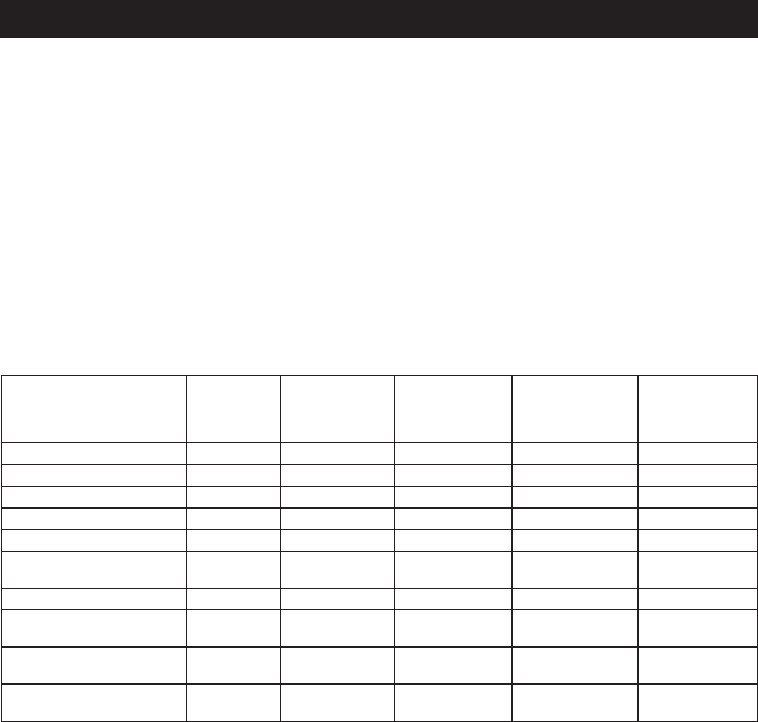
16 — Français
ENTRETIEN
CALENDRIER D’ENTRETIEN
NOTE : Siunautremanueldumoteurestfourniaveccettegénératrice,veuillezrespecterlecalendrierd’entretienprésentédans
le manuel du moteur au lieu de suivre les instructions d’entretien décrites ci-dessous.
Avant
chaque
utilisation
Après 1 mois
ou 10 heures de
fonctionnement
Tous les 3 mois
ou 50 heures de
fonctionnement
Tous les 6 mois
ou 100 heures de
fonctionnement
Chaque année
ou toutes les
300 heures de
fonctionnement
Vérifier l’huile moteur
Changer l’huile moteur
Vérifier le filtre à air
Nettoyer le filtre à air2
Remplacer le filtre à air2
Vérifier/régler l’écartement
de la bougie
Remplacer la bougie2
Vérifier/régler le jeu des
soupapes1,2
Nettoyer le réservoir de
carburant et le filtre1
Vérifier le tube de
carburant
1. Ceci ne doit être effectué que par un centre de réparations agréé.
2. Consulter le manuel du moteur pour prendre connaissance du calendrier d’entretien de cet article.
NOTE : L’entretien doit être effectué plus fréquemment lorsque le générateur est utilisé dans des zones poussiéreuses.
Lorsquelegénérateuradépassélesvaleursmaximumindiquéesdansletableau,l’entretiendoitcontinueràêtreeffectuéselon
les intervalles ou aux fréquences indiqués.
Retirerlebouchonduréservoir.
Pencher la génératrice sur le côté afin de verser l’huile usée
dans un contenant approuvé, en la drainant par l’orifice de
remplissage.
Lorsquelecarburantestvidangéduréservoir,replacerle
bouchonduréservoir.
Vidanger le carburant du carburateur
Mettrelecommutateurmarche/arrêtsurMARCHE ( I ).
Desserrer la vis située sur le dessus du capot moteur. Retirer
le couvercle et mettre de côté.
Placer un récipient adapté sous la vis de vidange du
carburateurpourrecueillirlecarburant;desserrerlavis.
Laisser le carburant se vidanger complètement dans le
récipient.
Resserrer la vis de vidange.
Mettrelecommutateurmarche/arrêtsurARRÊT ( O ).
NOTE : Consulter les directives d’élimination des déchets
localespouréliminerlecarburantcorrectement.
TRANSPORT
Mettrelecommutateurmarche/arrêtsurARRÊT ( O ).
S’assurerquelemoteuretl’échappementdel’unitésont
froids.
Garder l’unité de niveau pendant le transport afin d’éviter
derenverserducarburant.
Nepasfairechuter,heurterouplacerl’unitésousdelourds
objets.
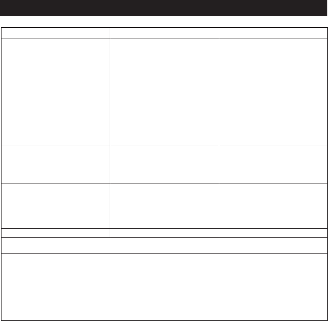
17 — Français
DÉPANNAGE
PROBLÈME CAUSE POSSIBLE SOLUTION
Le moteur ne démarre pas. Le commutateur marche/arrêt est sur
ARRÊT (O).
Pasdecarburant.
Niveaud’huilebas.
Bougiedéfectueuse,encrasséeou mal
écartée.
Le levier d’étranglement est en position
RUN(MARCHE).
Moteurremisésanstraitementouvidange
de l’essence, ou plein fait avec un mauvais
carburant.
Filtre à air encrassé.
Mettrelecommutateurmarche/arrêtsur
MARCHE (I).
Remplirleréservoirdecarburant.
Vérifier le niveau d’huile moteur et faire
l’appoint si nécessaire.
Remplacerlabougie.
Tirerlelevierdel’étrangleursurFERMÉ.
Vidangerle carburant et le carburateur.
Remplir d’essence fraîche.
Contacter un centre de réparations
agréé.
Le moteur manque de puissance. Moteurremisésanstraitementouvidange
de l’essence, ou plein fait avec un mauvais
carburant.
Filtre à air encrassé.
Vidangerle carburant et le carburateur.
Remplird’essencefraîche.Sileproblème
persiste, contacter le centre de réparation
agréé le plus proche.
Nettoyerouremplacerselonlebesoin.
La prise c.c. ne fonctionne pas. Disjoncteur déclenché
L’appareilbranchéestdéfectueux.
Débranchertoutesleschargesdugénéra-
teur. Régler l’interrupteur du moteur à la
position«OFF»(O)(arrêt),puisappuyer
sur le disjoncteur c.c. Voir la figure 20.
Essayerunautrearticle.
La prise c.a. ne fonctionne pas. L’appareilbranchéestdéfectueux. Essayerunautrearticle.
Sileproblèmepersisteaprèsavoiressayélessolutionsci-dessus,contacterlecentrederéparationsagrééleplusprochepour
obtenirdel’aide.
Lessymptômessuivantspeuventindiquerdesproblèmesaffectantleniveaud’émissionsdel’unité:
Démarrage difficile ou calage après le démarrage
Ralenti irrégulier
Ratés ou retours de flamme sous charge
Post-combustion(retoursdeflamme)
Fuméed’échappementnoireouconsommationdecarburantélevée
Encasdeprésenced’undecessymptômes,faireinspecterl’unitéetlafaireréparerparlecentrederéparationsagrééleplus
proche.

18 — Français
GARANTIE
VOS DROITS ET RESPONSABILITÉS EN VERTU DE CETTE GARANTIE
L’U.S.EnvironmentalProtectionAgency(EPA)etYongkang Zhongjian Tools Manufacture Co., Ltd (ci-après «
Zhongjian ») se font ici le plaisir de vous expliquer la garantie de conformité du dispositif antipollution de votre nouveau
petit moteur hors route. Tout nouveau petit moteur hors route doit être conçu, construit et équipé conformément aux
strictes réglementations antipollution de l’EPA. Zhongjian doitgarantirlesystèmedecontrôledesémissionsdespetits
moteurshorsroutepourlapériodeindiquéeci-dessus,àconditionqu’ilsn’aientpasfaitl’objetd’unusageabusif,
d’une modification non approuvée ou d’un manque d’entretien.
Votresystèmedecontrôledesémissionspeutincluredespiècestellesquelecarburateur,lesystèmed’allumage,
lesystèmed’admissionetlesystèmed’échappement,ainsiqued’autrespiècesconnexes.Dansl’éventualitéd’un
problèmecouvertparlagarantie,Zhongjian s’engage à réparer gratuitement votre moteur hors route, ce qui comprend
le diagnostic, les pièces et la main-d’œuvre.
DURÉE DE LA GARANTIE DU FABRICANT SUR LE DISPOSITIF ANTIPOLLUTION :
Lessystèmesantipollutiondesmoteursdesmodèles2011etultérieurssontgarantispourunepériodededeuxans
telqu’indiquéci-après.Si,aucoursdecettepériodedegarantie,l’unoul’autredescomposantsoudesdispositifs
liésauxémissionsprésenteunvicedematériauoudefabrication,laréparationouleremplacementducomposant
ou du dispositif sera effectué par un centre de service agréé des produits Zhongjian.
RESPONSABILITÉS DE L’ACHETEUR OU DU PROPRIÉTAIRE AU REGARD DE LA GARANTIE :
En tant qu’acheteur ou propriétaire de ce petit moteur hors route, vous êtes tenu d’effectuer les séquences d’entretien
indiquéesdanslemanueldupropriétairefourniparlefabricant.Auxfinsdelagarantie,Zhongjian recommande de
conserver tous les reçus relatifs à l’entretien du moteur. Toutefois, Zhongjian ne peut pas refuser la couverture de
la garantie pour l’unique raison du manque de reçus ou parce que vous avez omis d’effectuer toutes les séquences
d’entretien prévues.
Toutefois, en tant qu’acheteur ou propriétaire du petit moteur hors route, vous devez savoir que Zhongjian peut nier
touteresponsabilitéettouteobligationdesaparttelquestipulédanslagarantiesiladéfaillancedecemoteuroud’une
desespiècesestdueàunusageabusif,àlanégligence,àunmauvaisentretien,àdesmodificationsnonapprouvées
ouencoreàl’utilisationdepiècescontrefaitesouprovenantdu«marchégris»etquin’ontpasétéfabriquées,fournies
ou approuvées par Zhongjian.
Vous êtes tenu de confier votre moteur à un centre agréé de service de la garantie de Zhongjiandèsqu’unproblème
seprésente.Lesréparationssousgarantieseronteffectuéesdansundélairaisonnablenedépassantpas30jours.
Pour fixer un rendez-vous d’entretien sous garantie, veuillez communiquer avec le détaillant ou un centre agréé de
service de la garantie de Zhongjian.Pourobtenirl’adresseducentreagréédeservicedelagarantiedeZhongjianle
plus près, composez le 1-800-860-4050.
GARANTIE CONFORMITÉ AUX NORMES DE L’EPA

19 — Français
GARANTIE
VOS DROITS ET RESPONSABILITÉS EN VERTU DE
CETTE GARANTIE
Le California Air Resources Board et Youngkang ZhongJian
Tools manufacture Co., Ltd sont heureux de vous expliquer la
garantiedusystèmeantipollutiondevotrepetitmoteurhorsroute
(SORE).TouslesnouveauxSOREutiliséSenCaliforniedoivent
être conçus, construits et équipés conformément aux normes
antismogdecetétat.YongkangZhongJianToolsmanufacture
Co.,Ltd.doitgarantirlesystèmeantipollutiondevotreSORE
pendantunepériode,déterminéeci-dessous,saufsileSORE
aétéabusé,négligéoumalentretenu.
Votre système antipollution peut inclure des pièces telles
qu'uncarburateur,desréservoirsàessence,desbouchonsde
réservoiràessence,conduitsd'essence,systèmed'allumageet
convertisseurcatalytique.Ilpeutégalementinclurelesboyaux,
courroies,connecteursetautresarticlesassociésausystème
antipollution.
Lorsqu'une condition est prévue par la garantie, Yongkang
ZhongJianToolsmanufactureCo.,Ltd.répareravotreSORE
sans frais incluant le diagnostique, les pièces et la main d'oeuvre.
COUVERTURE DE LA GARANTIE DU FABRICANT :
Le système antipollution est garanti pendant deux (2) ans.
Toutepiècedéfectueuseassociéeausystèmeantipollutiondu
moteurseraréparéeouremplacéeparYongkangZhongJian
Tools manufacture Co., Ltd.
RESPONSABILITÉS DU PROPRIÉTAIRE DANS LE
CADRE DE LA GARANTIE :
Le propriétaire de ce moteur est tenu d'effectuer les
entretiens nécessaires décrits dans le manuel du propriétaire.
Youngkang ZhongJian Tools manufacture Co., Ltd vous
recommande de conserver tous vos reçus d'entretien de
votreSORE,maisYoungkangZhongJianToolsmanufacture
Co., Ltd ne peut renier sa garantie uniquement pour manque
de reçus ou pour le fait que vous n'avez pas respecté tous
les entretiens prévus.
Entantquepropriétaired'unSORE,vousdeveztoutefois
êtreinforméqueYongkangZhongJianToolsmanufacture
Co., Ltd. Peut renier votre couverture de garantie si
votre SORE ou l'une de ces pièces a été endommagé
par une utilisation abusive, la négligence, un entretien
inadéquat ou par des modifications non approuvées.
VousêtesresponsabledeprésentervotreSOREàunCentre
dedistributionouCentredeserviceautoriséparYongkang
ZhongJianToolsmanufactureCo.,Ltd.Dèsqueleproblème
survient. Les réparations sous garantie seront effectuées
dansundélairaisonnable,nedépassantpas30jours.
Pour toutes questions au sujet de la couverture de la garantie,
vousdevezcommuniqueraveclereprésentantduServiceàla
clientèledeYongkangZhongJianToolsmanufactureCo.,Ltd.
en appelant au numéro 1-877-218-5285.
ÉNONCÉ DE GARANTIE DU SYSTÈME ANTIPOLLUTION DE LA CALIFORNIE
COUVERTURE DE LA GARANTIE DES DÉFAUTS :
Adopté par le Air Resources Board, Yongkang Zhongjian
fabricationToolsCo.,Ltdgarantitàl'acheteurinitialetàchaque
acheteursuivantquelepetitmoteurhorsroute(SORE)(1)aété
conçu, construit et équipé pour répondre à tous les règlements en
vigueur;et(2)estexemptdevicesdematériauxetdefabrication
pouvant provoquer la défaillance d'une pièce garantie nuisant
àlaconformitédesrèglements,quipeuventêtreapplicables
aux clauses et conditions énoncées ci-dessous.
(a) La période de la couverture commence à la date de
livraison du moteur à l'acheteur. La garantie est d'une
durée de deux ans.
(b)La garantie est assujettie à certaines conditions et
restrictions. La garantie sur les pièces associées au
systèmeantipollutionserainterprétéecommesuit:
(1) Toute pièce garantie dont le remplacement n'est pas
prévu par les exigences d'entretien décrites dans votre
Manueld'utilisateurestgarantiepourlapériodestipulée
ci-dessous.Siunepièceestdéfectueusependantlapériode
de couverture de la garantie, cette pièce sera réparée ou
remplacéeparYongkangZhongJianToolsmanufactureCo.,
Ltd. Conformément au sous-article (4) ci-dessous. Toute
pièce de ce genre réparée ou remplacée dans le cadre de
cette garantie est garantie pour le restant de la période.
(2) Toute pièce garantie prévue uniquement lors d'une
inspectionpériodiquedansvotreManueldel'utilisateurest
garantie pour la période de garantie stipulée ci-dessus. Toute
pièce réparée ou remplacée dans le cadre ce cette garantie
sera garantie pour le reste de la durée de la garantie.
(3) Toute pièce qui doit être remplacée conformément au
calendrier d'entretien comme décrit aux instructions selon
votre manuel du propriétaire est garantie pour la période
de temps précédant le premier remplacement prévu pour
cettepièce.Siunepièceestdéfectueuseavantlepremier
remplacement prévu, la pièce sera réparée ou remplacée
par Yongkang ZhongJian Tools manufacture Co., Ltd.
Conformément au sous-article (4) ci-dessous. Toute pièce
de ce genre réparée ou remplacée dans le cadre de cette
garantie est garantie pour le restant de la période qui précède
la première échéance de remplacement.
(4) La réparation ou le remplacement de toutes pièces garanties
au titre de cette garantie doit être effectué sans frais pour
le propriétaire à un centre de garantie.
(5) Nonobstant les dispositions des présentes, les services
de garantie ou de réparation seront fournis à tous nos
centresdedistributionquisontfranchiséspourleservice
des moteurs en question.
(6) Lepropriétairedumoteurnedoitpasdébourserlesfraispour
la main d'oeuvre du diagnostic menant à la détermination
qu'une pièce garantie est effectivement défectueuse, pourvu
que cette main d'oeuvre de diagnostic soit effectuée par
un centre de garantie.

20 — Français
GARANTIE
(7) Yongkang ZhongJian Tools manufacture Co., Ltd. est
responsabledesdommagesauxcomposantsdumoteur
étroitement reliés à une pièce défectueuse couverte par la
garantie de toutes pièces sous garantie.
(8) Pendant la période de garantie du moteur stipulée ci-dessus,
YongkangZhongJianToolsmanufactureCo.,Ltd.gardera
un stock de pièces garanties suffisant pour répondre à une
telle demande de telles pièces.
(9) Toute pièce de remplacement peut être utilisée pour tout
entretien ou réparation sous garantie, et être fournie au
propriétaire sans frais. Une telle utilisation ne diminue pas
lesobligationsdegarantiedeYongkangZhongJianTools
manufacture Co., Ltd.
(10) Des ajouts ou des pièces modifiées non exonérés par Air
ResourceBoardnepeuventpasêtreutilisés.L'utilisation
d'ajouts non exonérés ou de pièces modifiées par l'acheteur
d'origine peut justifier le refus d'une réclamation au titre de
lagarantie.YongkangZhongJianToolsmanufactureCo.,
Ltd.n'est pas responsablede garantir lesdéfectuosités
des pièces garanties causées par l'utilisation d'ajout non
exonéré ou de pièce modifiée.
(11)Lefabricantémetteurdelagarantiedoitfournirtousles
documents décrivant les procédures de garantie ou de
politiquesdufabricantdanslescinqjoursouvrablessuivant
unerequêteduAirResourcesBoard.
PÉRIODES DE GARANTIE :
La réparation ou le remplacement de toutes pièces garanties
autrementadmissibleàunecouverturedegarantiepeutêtre
excludecouverturedegarantiesiYongkangZhongJianTools
manufactureCo.,Ltd.démontrequelemoteuraétéabusé,
négligéoumalentretenu,etquedetelsabus,denégligence,de
mauvais entretien a été la cause directe de la nécessité d'une
réparation ou le remplacement de la pièce. En dépit de cela,
tout réglage d'un composant doté d'un dispositif installé en
usineetquifonctionnecorrectementdemeureadmissibleàla
couvertureparlagarantie.Lespiècesdusystèmeantipollution
garanties pour chaque liste de famille de moteur de la liste
suivante sont couvertes.
Pour les moteurs des familles BZJTS.0404YY et
BZJTS.0541YY :
(1) Systèmedudoseurd'essence:
(a)Ensemblecarburateuretsescomposantsinternes(si
équipé)
(b)Filtreàcarburant(siéquipé)
(c)Jointsstatiquesducarburateur
(d)Pompeàcarburant(lecaséchéant)
(2) Systèmed'admissiond'air,incluant:
(a)Tuyau/tubulured'admission
(b)Filtreàair
(3) Systèmed'allumage,incluant:
(a)Bougie
(b)Module/bobined'allumage
ÉNONCÉ DE GARANTIE DU SYSTÈME ANTIPOLLUTION DE LA CALIFORNIE
(continu)
(4) Ensemblecatalytiquedusilencieux(siéquipé),incluant:
(a)Jointd'échappement
(b)Tubulured'échappement
(5) Assemblagedureniflard,incluant:
(a)Tubuluredebranchementdureniflard.
(6) Pièces diverses utilisées pour les systèmes ci-dessus,
incluant :
(a) Commutateurs
(b)Tuyauxflexibles,courroies,connecteursetmodules.
(7) Système d'évaporation des émissions du réservoir à
essence, incluant :
(a) Réservoir à essence
Pour moteur de la famille BZJTS.1061YY :
(1) Systèmedudoseurd'essence:
(a)Ensemblecarburateuretsescomposantsinternes
(b)Jointsstatiquesducarburateur
(c) Réservoir à essence
(f) Canalisation d'essence
(g) Raccords de la canalisation d'essence
(h) Fixations
(2) Systèmed'admissiond'air,incluant:
(a) Intake pipe/manifold
(b)Aircleaner
(3) Systèmed'allumage,incluant:
(a)Bougie
(b)Bobined'allumage
(4) Ensemblecatalytiquedusilencieux(siéquipé),incluant:
(a)Jointd'échappement
(b)Tubulured'échappement
(c)Convertisseurcatalytique
(5) Assemblagedureniflard,incluant:
(a)Tubuluredebranchementdureniflard.
(6) Système d'évaporation des émissions du réservoir à
essence, incluant :
(a)Soupapesdepurge
(b)Réservoiràcharbonactif
(c)Supportsdemontageduréservoir
(d)Bouchonsderéservoiràessence
(e) Réservoir à essence
(6) Pièces diverses utilisées pour les systèmes ci-dessus,
incluant :
(a) Commutateurs
(b)Tuyauxflexibles,courroies,connecteursetmodules.
(7) Systèmeàinjectiond'air
(a) Valve d'impulsion
Cettegarantieestfournieconformémentàl’«Énoncédegarantie
dusystèmeantipollutiondelaCalifornie».

21 — Français
GARANTIE
TechtronicIndustriesNorthAmerica,Inc.(désignéci-après
« Techtronic Industries »), garantit à l’acheteur original
que chaque nouveau moteur qui est vendu est exempt de
toutvicedematériauoudefabricationpendantlapériode
indiquée ci dessous (à partir de la date d’achat) dans des
conditions normales d’utilisation et sous condition d’un
entretien normal. Dans le cadre de cette garantie limitée,
Techtronic Industries contracte une obligation envers sa
clientèle qui se limite à la réparation ou au remplacement (au
choix de l’entreprise) de toute pièce jugée, après évaluation
de Techtronic Industries, comme présentant des vices de
matériauoudefabrication.Toutefois,auxtermesdecette
garantie, l’obligation imposée à Techtronic Industries est
limitée par une condition selon laquelle l’entreprise, ou l’un
desesdistributeursoudesescentresderéparationsagréés
autorisés à procéder à l’entretien du moteur, doit recevoir la
réclamation au titre de la garantie ou la pièce ou les pièces
défectueuses en temps opportun, avec les frais de transport
payésaupréalable,poureffectueruneinspectionetune
réparation. Toutes les demandes de réparation qui respectent
les conditions de la garantie limitée doivent être traitées par
TechtronicIndustriesorouparl’undesesdistributeursou
de ses centres de réparations agréés.
WARRANTY PERIODS:
Moteur à essence 158F (privé/résidentiel), garantie
limitée de deux ans
Moteurs à essence 158F (commerciaux), garantie limitée
de 90 jours
Tel que mentionné précédemment, la réparation ou le
remplacement de toute pièce en application de cette garantie
limitée ne doit pas s’étendre au delà des termes d’origine
de la garantie sur le moteur.
LIMITES ET EXCLUSIONS : Cette garantie limitée ne
s’applique pas aux éléments suivants :
1 Les réparations requises en raison d’un entreposage
prolongé, ce qui inclut les dommages causés par le
carburant usé ou contaminé contenu dans le réservoir,
la canalisation d’essence et le carburateur; les valves
poisseuses, et la corrosion et la rouille des pièces du moteur.
2 Lesréparationsrequisesenraisond’unesurchauffe(leplus
souvent causée lorsqu’un volant, un ventilateur, une entrée
d’air, une ailette de refroidissement ou une grille de prise d’air
sontsurchargés,bouchés,manquantsouendommagés).
3 L’usure liée à la poussière ou au sable et causée par
l’entretien inadéquat du purificateur d’air (se traduisant le plus
ÉNONCÉ DE LA GARANTIE LIMITÉE DU MOTEUR
souvent par l’usure des pistons, des segments de piston,
descylindres,dessoupapes,desguidesdesoupape,du
carburateuroud’autrescomposantsinternes).
4 Lespiècesbriséesourayéesenraisondubasniveaude
lubrifiantoudel’utilisationdelubrifiantusagéeoudecalibre
inadéquat.
5 La mise au point du moteur ou tout entretien normal,
y compris, mais non de façon limitative, le réglage des
soupapes,leremplacementnormaldespièces,ducarburant,
delelubrifiant,etc.
6 Toutedéfectuositédumoteurattribuableàlanégligence,
àunemauvaiseutilisation,àunaccidentouàl’emballement.
7 Touteinstallation,réparationoumodificationdumoteur
qui, selon Techtronic Industries, nuit à son rendement ou à
safiabilité.
8 Touteinstallationouréparationdumoteureffectuéeàl’aide
depiècesoudecomposantsquin’ontpasétéfabriqués
ouapprouvésparSubaruRobin.L’entrepriseestlibrede
juger si les pièces ou les composants en question nuisent
aurendementouàlafiabilitédumoteur.
9 Toute situation où un composant ou un moteur est
totalement usé en dépit d’une utilisation normale.
Le client doit assumer tous les frais de transport liés aux
travaux relatifs aux garanties.
Techtronic Industries se réserve le droit de modifier ou
d’améliorer tous les moteurs et les pièces sans contracter
l’obligationdemodifierouderemplacerlesmoteursetles
pièces vendus avant la mise en oeuvre de ces modifications
ou de ces améliorations.
Nul n’est autorisé à offrir une garantie supplémentaire
ouàassumerd’autresobligationsaunomdeTechtronic
Industries à moins qu’une preuve écrite signée par un agent
de l’entreprise ne soit présentée.
LA PRÉSENTE GARANTIE AINSI QUE L’OBLIGATION DE
TECHTRONIC INDUSTRIES DÉCRITE AUX PRÉSENTES
REMPLACENT TOUTES LES AUTRES GARANTIES OU
OBLIGATIONS, EXPRESSES OU IMPLICITES, CE QUI
INCLUT TOUTE GARANTIE DE QUALITÉ MARCHANDE
OU DE QUALITÉ DE CONVENANCE À DES FINS
PARTICULIÈRES. AUCUNE GARANTIE NE VA AU DELÀ
DE LA DESCRIPTION FOURNIE AUX PRÉSENTES..
TECHTRONIC INDUSTRIES NE PEUT EN AUCUN CAS
ÊTRE TENU RESPONSABLE POUR TOUT DOMMAGE
DIRECT OU INDIRECT.
POURTOUTEQUESTIONCONCERNANTVOSDROITSETVOSRESPONSABILITÉSAUTITREDELAGARANTIE,
VEUILLEZCOMMUNIQUERAVECLECENTREDERÉPARATIONSRYOBIAGRÉÉLEPLUSPROCHEAU1-800-860-4050.

22 — Français
GARANTIE
ÉNONCÉ DE LA GARANTIE LIMITÉE
TechtronicIndustriesNorthAmerica,Inc.,garantitàl’acheteur
originalqueceproduitRYOBI® est exempt de tous vices
de matériaux ou de fabrication et s’engage à réparer ou
remplacer gratuitement, à son choix, tout produit s’avérant
défectueux au cours des périodes indiquées ci-dessous, à
compter de la date d’achat.
Troisanssurlesproduitsutiliséspardesparticuliers;
90 jours sur les produits utilisés à toutes autres fins, telles
que les travaux commerciaux et la location.
Cette garantie n’est offerte qu’à l’acheteur original et entre
en vigueur à la date de l’achat original.
Toutepiècedeceproduitjugée,aprèsévaluationraisonnable
par Techtronic Industries North America, Inc., comme
présentantdesvicesdematériauxoudefabrication,sera
réparée ou remplacée, sans facturation pour pièces ou main
d’oeuvre par un centre de réparations agréé pour produits
d’extérieurdemarqueRYOBI®(centrederéparationsRyobi
agréé).
Leproduit,ycompristouteslespiècesdéfectueusesdevront
êtreretournésàuncentrederéparationsRyobiagréé,avant
expiration de la période de garantie. Les frais d’expédition
au centre de réparations pour les travaux sous garantie et
de retour au propriétaire du produit seront assumés par le
propriétaire. En ce qui concerne les réclamations en garantie,
laresponsabilitéTechtronicIndustriesNorthAmerica,Inc.,
se limitera à la réparation ou au remplacement des produits
défectueux et aucune revendication de rupture de garantie
ne pourra causer l’annulation ou la résiliation du contrat de
vented’unproduitd’extérieurRYOBI® quel qu’il soit. Une
preuve d’achat sera exigée par le centre de réparation, afin
de valider toute réclamation au titre de la garantie. Toutes
les réparations sous garantie devront être effectuées par un
centre de réparations agréé.
Lagarantiesurtoutproduitd’extérieurRYOBI® utilisé pour
la location, des travaux commerciaux ou tout autre usage
lucratif, sera limitée à quatre-vingt-dix (90) jours, à compter
de la date d’achat au détail original.
Cettegarantienecouvrepaslesproduitsayantfaitl’objet
d’unusageabusifounégligent,d’unemauvaiseutilisation
oud’unmanqued’entretien,ouayantétéimpliquésdansun
accident,soumisauxeffetsdelacorrosionouemployésde
façon contraire aux instructions du manuel d’utilisation. Cette
garantie ne couvre ni les dommages aux produits résultant
d’un manque d’entretien, ni les produits qui ont été altérés
ou modifiés. La garantie exclut les réparations rendues
nécessaires par l’usure normale ou l’utilisation de pièces et
d’accessoiresincompatibles avec ce produitextérieur de
marqueRYOBIMCounuisiblesàsonbonfonctionnement,
sesperformancesousadurabilité.
En outre, la présente garantie exclut:
Lesréglages-Bougies,carburateur,réglagesducarburateur,
allumage, filtres, changement d'huile
L’usuredespièces–cordedulanceur,balaisdemoteur,
balaisd’alternateur,goupillesenépingleàcheveux,meules,
tuyauhautepression,lanced’arrosage,buses,poignéeà
gâchette, tuyaux d’alimentation, raccords rapides, joints,
vannes,pistons,ensemblesdesoupapedepompe,joints
toriques, joints d’eau et d’huile, réservoirs de détergent.
L’entreprise n’assumera en aucun cas les frais liés à la
réparation ou à l’ajustement du produit, ou les coûts
associésàdestâchespourlesquellesellen’apasdonné
son consentement.
TechtronicIndustriesNorthAmerica,Inc.,seréserveledroit
d’apporter des modifications ou améliorations à tout produit
extérieurRYOBI®,sansobligationdemodifierlesproduits
fabriquésantérieurement.
LADURÉEDETOUTESLESGARANTIESIMPLICITESNE
SAURAIT EN AUCUN CAS EXCÉDER LA PÉRIODE DE
GARANTIEDÉCLARÉE.PARCONSÉQUENT,TOUTESLES
GARANTIESIMPLICITES,YCOMPRISLESGARANTIES
DEVALEUR MARCHANDE OU D’ADÉQUATION À UN
USAGEPARTICULIEROUAUTRESSERONTINVALIDÉESÀ
L’EXPIRATIONDELAPÉRIODEDEGARANTIEAPPROPRIÉE
DETROISANSOUQUATRE-VINGT-DIX JOURS. LES
OBLIGATIONS DE TECHTRONIC INDUSTRIES NORTH
AMERICA,INC.,DANSLECADREDECETTEGARANTIE
SELIMITENTEXCLUSIVEMENTÀLARÉPARATION OU
AUREMPLACEMENTDESPIÈCESDÉFECTUEUSES
ETTECHTRONICINDUSTRIESNORTH AMERICA, INC.
N’ASSUMEOU N’AUTORISEQUICONQUE ÀASSUMER
QUELQUEAUTREOBLIGATIONQUECESOIT.CERTAINS
ÉTATS ET PROVINCES NE PERMETTANT PAS DE
LIMITATION DE DURÉE DES GARANTIES IMPLICITES,
LES RESTRICTIONS CI-DESSOUS PEUVENT NE PAS
ÊTREAPPLICABLES.TECHTRONICINDUSTRIESNORTH
AMERICA,INC.,DÉCLINETOUTERESPONSABILITÉENCE
QUICONCERNELESDOMMAGESDIRECTS,INDIRECTS
OU AUTRES, Y COMPRIS, MAIS SANS S’Y LIMITER,
LESFRAISDERETOURDEPRODUITSÀUNCENTRE
DE RÉPARATION RYOBI AGRÉÉ ET DE RENVOI AU
PROPRIÉTAIRE,DEDÉPLACEMENTD’UNTECHNICIEN,
DE TÉLÉPHONE OU TÉLÉGRAMME, DE LOCATION
D’UN PRODUIT SIMILAIRE PENDANT LA DURÉE DES
RÉPARATIONSSOUSGARANTIE,DEDÉPLACEMENT,DE
PERTESOUDOMMAGESÀDESBIENSPERSONNELS,DE
MANQUEÀGAGNER,DEPERTED’USAGEDUPRODUIT,
DEPERTEDETEMPSOUDEDÉRANGEMENT.CERTAINS
ÉTATSETPROVINCESNEPERMETTANTL’EXCLUSIONOU
LALIMITATIONDESDOMMAGESDIRECTSOUINDIRECTS,
LESRESTRICTIONSCI-DESSOUSPEUVENTNEPASÊTRE
APPLICABLES.
Cette garantie donne au consommateur des droits
spécifiques,etcelui-cipeutbénéficierd’autresdroits,qui
varient selon les états ou provinces.
Cettegarantiecouvretouslesproduitsd’extérieurRYOBI®
fabriquésparTechtronicIndustries North America, Inc.,
vendusauxÉtats-UnisetauCanada.
Pourobtenirl’adresseducentrederéparationsRyobiagréé
le plus proche, appeler le 1-800-860-4050.

22 - English
NOTES
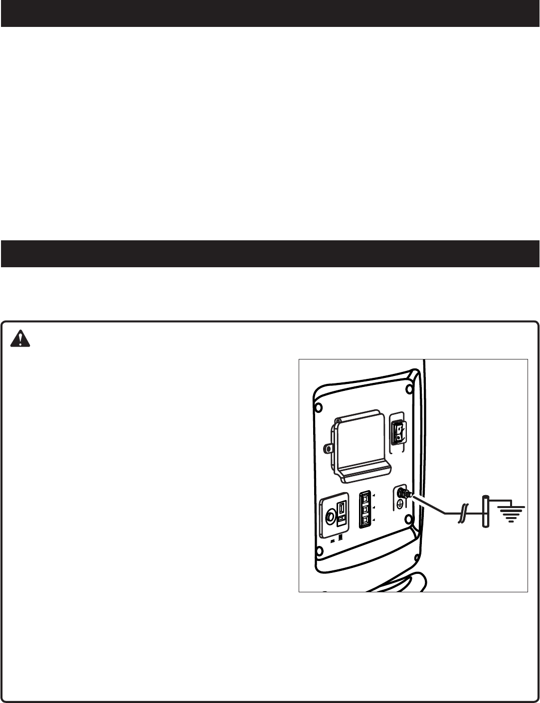
2 — Español
ÍNDICE DE CONTENIDO
INTRODUCCIÓN
Introduction ................................................................................................................................................................................ 2
Instrucciones de seguridad importantes .................................................................................................................................3-4
Reglas de seguridad específicas ............................................................................................................................................... 4
Simbolos .................................................................................................................................................................................5-7
Aspectos eléctricos .................................................................................................................................................................7-9
Características .....................................................................................................................................................................9-10
Armado ..................................................................................................................................................................................... 11
Funcionamiento ...................................................................................................................................................................12-14
Mantenimiento ....................................................................................................................................................................14-16
Correccióndeproblemas ......................................................................................................................................................... 17
Garantía ............................................................................................................................................................................... 18-22
Pedidosdepiezas/Servicio ..................................................................................................................................Pág. posterior
PELIGRO:
CONEXIÓN A TIERRA DEL GENERADOR
Para reducir el riesgo de descarga o electrocución, el generador
debeconectarseatierracorrectamente.Siempredebeutilizarsela
tuercayelterminaldeconexiónatierradelbastidorparaconectarel
generador a una fuente apropiada de conexión a tierra. La conexión
atierradeberealizarseconalambrecalibreNº8.Conecteelterminal
delalambredeconexiónatierraentrelaarandelaylatuerca,y
aprietefirmementelatuerca.Conecteelotroextremodelalambre
firmemente a una fuente apropiada de conexión a tierra.
ElCódigoEléctricoNacionalespecificavariasmanerasprácticas
paraestablecerunabuenafuentedeconexiónatierra.Siseutiliza
unabarradeaceroodehierro,éstedebeserde15,9mm(5/8pulg.)
dediámetro,ysiseutilizaunabarranoferrosa,éstadebeserde
13mm(1/2pulg.)dediámetrocomomínimoyestarlistadacomo
materialadecuadoparaconexiónatierra.Hinquelabarraotubo
hastauna profundidadde 2,44m(8 pies).Sise encuentra roca
sólidaamenosde1,22m(4pies)deprofundidad,entierrelabarra
otuboenunazanja.
Todaslasherramientaseléctricasyaparatosalimentadosporeste
generadordebenconectarseapropiadamenteatierramedianteel
usodeunterceralambreotenerundiseñocon“dobleaislamiento”.
Serecomienda:
1. Usardispositivoseléctricosconclavijadetrespatillasconectadaatierra.
2. Paraasegurarlacontinuidaddelaproteccióna tierra del generador al dispositivo, utilice un cordón de extensión
conunreceptáculodetresorificiosenunextremoyunaclavijadetrespatillasenelotro.
Reviseycumplacontodaslasreglasfederales,estatalesylocalesrelevantesenrelaciónconlasespecificacionesdeconexión
atierra.Consulteaunelectricistacalificadootécnicodeserviciosinohacomprendidocompletamentelasinstruccionesde
conexión a tierra o si no está seguro si el generador está conectado a tierra correctamente.
Esteproductoofrecenumerosascaracterísticasquehacenelusodelmismomásplacenteroyagradable.Eneldiseñodeeste
productosehaconferidoprioridadalaseguridad,aldesempeñoylafiabilidad,porlocualsefacilitasumanejoymantenimiento.
O
V
E
R
L
O
A
D
PO
W
E
R
L
O
W
O
I
L
G
R
O
U
N
D
O
F
F
O
N
A
U
T
O
I
D
L
E
:
12
V
5
A
S
U
RG
E
P
R
O
T
E
C
T
O
R
O
F
F
O
N
3 — Español
INSTRUCCIONES DE SEGURIDAD IMPORTANTES
PELIGRO:
Monóxido de carbono. Usar un generador en el interior LO
MATARÁENPOCOSMINUTOS.
Losgasesdeescapedelgeneradorcontienennivelesaltos
demonóxidodecarbono(CO),ungasvenenosoqueno
puedeverseniolerse.Sipuedeolerlosgasesdeescape
del generador, está respirando CO. Pero incluso si no puede
olerlosgasesdeescape,esposiblequeestérespirandoCO.
Nuncauseungeneradordentrodesuhogar,garaje,
sótano, ni demás espacios parcialmenteencerrados. En
dichosespacios,puedenacumularsenivelesmortales
demonóxidodecarbono.Usarunventiladoroabrir
puertas y ventanas NO proporciona suficiente aire
fresco.
SÓLOutiliceelgeneradoralairelibreylejosdeventanas,
puertasyrespiraderosabiertos.Estasaberturaspueden
atraer los gases de escape del generador.
Incluso si utiliza el generador correctamente, el CO puede
ingresarensuhogar.SIEMPREutiliceunaalarmadeCOde
pilasoconpilasderespaldoensuhogar.
Si comienza a sentirse descompuesto, mareado o débil
luegodequeelgeneradorestuvofuncionando,trasládese
adondehayaairefrescoINMEDIATAMENTE.Veaaundoctor.
Puedesufririntoxicaciónpormonóxidodecarbono.
ADVERTENCIA:
Lea y comprenda todas las instrucciones. El incumplimiento
de cualquiera de las instrucciones siguientes puede causar
electrocución, incendio o intoxicación por monóxido de
carbono,locualpuedecausarlamuerteolesionesgraves.
ADVERTENCIA:
El Reglamento Nacional de Electricidad exige que el
generador esté conectado a una tierra aprobada. Antes
de utilizar la terminal de tierra, consulte a un electricista
calificado, inspector de instalaciones eléctricas u organismo
gubernamentaldelalocalidadenloreferentealasreglasy
disposiciones relacionadas con el uso deseado del generador.
GUARDE ESTAS INSTRUCCIONES
Este manual contiene instrucciones importantes para
este producto que debe ser seguido durante instalación y
mantenimiento del generador.
Noconectelaunidadalsistemaeléctricodeunedificioa
menos que el generador y el interruptor de transferencia se
hayaninstaladocorrectamenteyqueunelectricistacalificado
hayaverificadolasalidadeenergíaeléctrica.
No permita que utilicen esta unidad niños ni personas
carentesdeladebidainstrucciónparasumanejo.
Nuncaarranqueniaccioneelmotordentrodeunáreatotal
oparcialmentecerrada.Lainhalacióndelasemanaciones
del escape puede ser mortal.
Alutilizarestaherramienta,póngaseprotecciónparalosojos
conlamarcadecumplimientodelasnormasANSIZ87.1,
así como protección para los oídos.
Mantenga a todos los circunstantes, niños y animales por
lomenosa3m(10pies)dedistancia.
Usebotasozapatosrobustosysecos.Noutilicelaunidad
estando descalzo.
No utilice este generador cuando se encuentre fatigado,
enfermoobajolosefectosdedrogas,alcoholomedicamentos.
Mantengatodaslaspartesdelcuerpoalejadasdetodapieza
móvilysuperficiecalientedelaunidad.
Notoquecablesnireceptáculosdesprovistosdeaislamiento.
Noutiliceelgeneradorconcordonesdecorrientegastados,
deshilachados,peladosodañadosdecualquierforma.
Antes de almacenar la unidad durante un período de tiempo
prolongado,dejequeelmotorseenfríeyretireelcombustible
de la unidad.
Noutiliceorguardeelgeneradorenlalluvia,nieveotiempo
húmedo.
Guardeel generador enunlugarbien ventilado y con el
tanquedecombustiblevacío.Elcombustiblenosedebe
guardar cerca del generador.
Antes de transportar la unidad en un vehículo, vacíe el
tanquedecombustible,cierrelaválvuladelcombustiblee
inmoviliceaquélla.
Deje enfriar el motor durante cinco minutos antes de
reabastecerlodegasolina.
Para reducir el riesgo de incendio o de lesiones por
quemadura, maneje con cuidado el combustible. Es
sumamenteinflamable.
No fume mientras esté mezclando el combustible o
reabasteciendoeltanque.
Almaceneelcombustibleenunrecipienteaprobadopara
gasolina.
Coloquelaunidadsobreelpisonivelado,apagueelmotor,
ydejequeseenfríeantesdereabastecerlodecombustible.
Aflojelatapadeltanquedecombustibleparaaliviarlapresión
yparaevitarqueseescapecombustibleporlatapa.
Despuésdereabastecerdecombustiblelaunidadponga
la tapa y apriétela firmemente.
Limpietodoelcombustiblequesehayaderramadodela
unidad.
Nunca intente en ninguna circunstancia eliminar el
combustiblederramadoquemándolo.
Losgeneradoresvibranduranteelusonormal.Durantey
después del uso del generador, inspeccione el generador,
así como los cordones de extensión y los cordones de
corriente conectados a éste, para ver si tienen daños
causadosporlavibración.Debenrepararseoreemplazarse
losartículosdañados,segúnseanecesario.Nouseenchufes
ni cordones que muestren señales de daño, como roturas
o agrietamientos en el aislamiento, o daño en las espigas.
Los generadores fijos instalados de manera permanente
sonlamejoralternativaparaabastecerdeelectricidadal
hogarduranteloscortesdeenergía.Inclusolosgeneradores
portátiles que están conectados correctamente pueden
4 — Español
INSTRUCCIONES DE SEGURIDAD IMPORTANTES
REGLAS DE SEGURIDAD ESPECÍFICAS
sobrecargarse. De esta manera, los componentes del
generador pueden recalentarse o exigirse demasiado, lo
que podría producir una falla en el generador.
Useúnicamenterepuestosyaccesoriosautorizadosysiga
las instrucciones descritas en la sección de Mantenimiento
de este manual. El empleo de piezas no autorizadas o el
incumplimiento de las instrucciones de mantenimiento puede
significar un riesgo de descarga eléctrica o de lesiones.
Mantengalaunidadsegúnlasinstruccionesdemantenimiento
señaladas en este manual del operador.
Inspeccionecadavezlaunidadantesdeusarlaparaversi
tienetornillosflojos,fugasdecombustible,etc.Reemplace
toda pieza dañada.
ADVERTENCIA:
Cuando este generador se utiliza para abastecer el
sistema de cableado de un edificio: un electricista
calificadodebeinstalarelgenerador,quedebeconectarse
auninterruptordetransferenciacomounsistemaderivado
independiente,deconformidadconelReglamentoNacional
de Electricidad (NFPA 70). El generador se conectará a
travésdeuninterruptordetransferenciaquecontrolatodos
los conductores, excepto el conductor de conexión a tierra
delequipo.Elbastidordel generadordebeconectarsea
unelectrododeconexiónatierraaprobado.Sinoseaísla
elgeneradordelaslíneasdealtovoltajepuedecausarsela
muerteolesionesalostrabajadoresdedichaslíneas.
NO utilice este generador para suministrar energía a
dispositivos de soporte vital o equipos médicos de
emergencia
Las emanaciones del escape contienen monóxido de
carbono,ungastóxicoincoloroeinodoro.Lainhalaciónde
las emanaciones del escape puede causar la pérdida de la
concienciaeinclusolamuerte.Siseutilizalaunidadenun
área total o parcialmente cerrada, el aire puede contener
unacantidadpeligrosademonóxidodecarbono.Paraevitar
la acumulación de las emanaciones del escape, siempre
asegúresedequequehayaventilaciónsuficiente.
Siempre use un detector de monóxido de carbono de
bateríasalutilizarelgenerador.Sicomienzaasentirsemal,
mareadoodébilalestarutilizandoelgenerador,apáguelo
yrespireairefrescodeinmediato.Veaaundoctor.Puede
sufririntoxicaciónpormonóxidodecarbono.
Coloqueelgeneradorenunasuperficieestablehorizontal
con una pendiente de no más de 4°.
Utilice la unidad al aire libre en un área bien ventilada e
iluminada, aislada de las áreas de trabajo para evitar la
interferencia del ruido.
Siseutilizaelgeneradorencondicioneshúmedas,puede
causarse una electrocución. Mantenga seca la unidad.
Mantenga el generador a una distancia mínima de 910 mm
(3pies)detodotipodematerialcombustible.
Noutiliceelgeneradorcercadematerialespeligrosos.
Noutiliceelgeneradorenunaestacióndeabastecimiento
de gasolina o gas natural.
Notoqueelsilenciadornielcilindroduranteelfuncionamiento
delaunidadniinmediatamentedespués;estánCALIENTES
y causan lesiones por quemadura.
Este generador tiene un punto neutro flotante. Esto significa
queelconductorneutronoestáconectadoporvíaseléctricas
al marco de la máquina.
No permita que se derrame el tanque del generador al
abastecerlodegasolina.Llénelohastaunaalturade25,4mm
(1po)abajodelcuellodeltanquedegasolinaparapermitir
laexpansióndelcombustible.
Nofumemientrasabastecedegasolinaelgenerador.
Apague el motor y déjelo enfriar por completo antes de
agregargasolinaolubricantealgenerador.
Noretirelavarilladeniveldeaceitenilatapadeltanquedel
combustiblemientrasestéfuncionandoelmotor.
Preste atención en particular a todas las etiquetas
deseguridadadheridasalgenerador.
En todo momento mantenga a los niños a una distancia
mínimade3m(10pies)delgenerador.
La unidad funciona mejor a una temperatura entre -5 y
40°C(23y104°F)conunahumedadrelativade90%o
menos.
Es necesario modificar el generador si va a utilizarse
siempreaunaaltitudsuperiora1524metros(5000pies).
Comuníqueseconelcentrodeservicioautorizadodesu
preferencia si necesita más información y para que realicen
tales modificaciones.
Elrequerimientodevoltajeyfrecuenciaoperativadetodoslos
equiposelectrónicosdebecomprobarseantesdeenchufarlos
a este generador. Pueden ocurrir daños si el equipo no está
diseñadoparaoperardentrode unavariacióndevoltaje
de+/-10%yunavariacióndefrecuenciade+/-3hzdelos
valoresnominalesqueaparecenenlaplacadeidentificación
del generador.
Guardeestasinstrucciones.Consúltelasconfrecuenciay
empléelas para instruir a otras personas que puedan utilizar
estaproducto.Siprestaaalguienestaproducto,facilítele
tambiénlasinstrucciones.
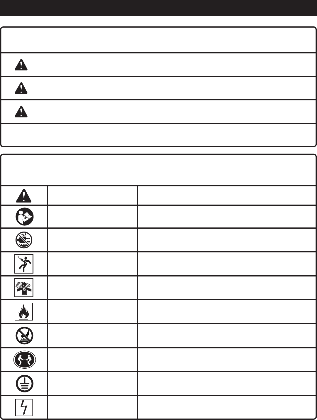
5 — Español
SÍMBOLOS
Esposiblequeseempleenenesteproductoalgunosdelossiguientessímbolos.Lesuplicamosestudiarlosyaprendersu
significado.Unacorrectainterpretacióndeestossímboloslepermitiráutilizarmejorydemaneramásseguraelproducto.
SÍMBOLO NOMBRE DENOMINACIÓN / EXPLICACIÓN
Alerta de seguridad Indicaunpeligroposibledelesionespersonales.
Lea el manual del operador Parareducirelriesgodelesiones,elusuariodebeleerycomprender
el manual del operador antes de usar este producto.
Alerta de condiciones
húmedas Noexpongalaunidadalalluvianilauseenlugareshúmedos.
Descargaeléctrica Sinoseusalaunidadencondicionessecasynoseobservanprácticas
segurasdetrabajo,puedeproducirseunadescargaeléctrica.
Emanaciones tóxicas
Conelfuncionamientodelgeneradorseemitemonóxidodecarbono,
ungastóxicoincoloroeinodoro.Siseinhalamonóxidodecarbono
puede causarse náusea, desmayo o la muerte.
Fuego / Explosión
Elcombustibleylosvaporesdel mismo son extremadamente
inflamablesyexplosivos.Elfuegoounaexplosiónpuedencausar
quemadurasgraveseinclusolamuerte.
Superficiecaliente Parareducirelriesgodelesionescorporalesodañosmaterialesevite
tocar toda superficie caliente.
Peligroallevantar Parareducirelriesgodelesionesserias, evite intentar levantar el
generador usted solo.
Conexión a tierra Consulte a un electricista de la localidad para determinar los requisitos
de conexión a tierra antes de utilizar la unidad.
Electrocución
El incumplimiento de conectar correctamente a tierra el generador
puede resultar en electrocución, especialmente si el generador está
equipadoconunconjuntodedisco.
Lassiguientespalabrasdeseñalizaciónysussignificadostienenelobjetodeexplicarlosnivelesderiesgorelacionadoscon
este producto.
SÍMBOLO SEÑAL SIGNIFICADO
PELIGRO: Indicaunasituaciónpeligrosainminente,lacual,sinoseevita,causarálesiones
gravesomortales.
ADVERTENCIA: Indicauna situaciónpeligrosaposible, la cual,sinose evita, podría causar
lesionesgravesomortales.
PRECAUCIÓN: Indicaunasituación peligrosaposible,lacual, si no se evita,podríacausar
lesionesmenoresoleves.
PRECAUCIÓN: (Sinelsímbolodealertadeseguridad)Indicaunasituaciónquepuedeproducir
daños materiales.
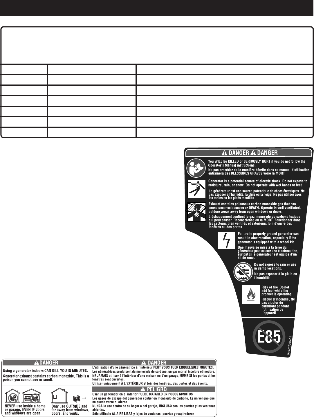
6 — Español
SÍMBOLOS
ETIQUETAS DE SEGURIDAD
La siguiente información puede encontrarse en el generador. Para su
propia seguridad, le sugerimos estudiar y entender todas la etiquetas
antesdeponermarchaelgenerador.
Sisedesprendedelaunidadcualquieradelasetiquetasosevuelven
ilegibles,comuníqueseconalgúncentrodeservicioautorizadopara
obtenerunreemplazo.
SE MATARÁ o LESIONARÁ GRAVEMENTE si no sigue las
instrucciones del Manual del operador.
Riesgodeincendio.Noagreguecombustiblecuandoelproducto
esté functionando.
Elgeneradoresunafuentepotencialdedescargaeléctrica.Noloexponga
ahumedad,lalluvianinalanieve.Noopereconmanosopieshúmedos.
Elescapecontienegasvenenosodemonóxidodecarbonoquepuedecausar
pérdidadelconocimientoalaMUERTE.Opereenáreasexterioresbienventiladas
lejosdepuertasoventanasabiertas.
La omisión de conectar a tierra adecuadamente el generador puede resultar en
electrocución, especialmente si el generador estáa equipado con un kit de ruedas.
Noexpongalaunidadalalluvianilauseenlugareshúmedos.
UsarungeneradorenelinteriorPUEDEMARTARLOENPOCOSMINUTOS.Losgases
deescapedelgeneradorcontienenmonóxidodecarbono.Esunvenenoquenopuede
verseniolerse.
NUNCAlousedentrodesuhogarodelgaraje,INCLUSOconlaspuertasylasventanas
abiertas.
SóloutilíceloALAIRELIBREylejosdeventanas,puertasyrespiraderos.
NousecombustibleE85.
Esposiblequeseempleenenesteproductoalgunosdelossiguientessímbolos.Lesuplicamosestudiarlosyaprender
susignificado.Unacorrectainterpretacióndeestossímboloslepermitiráutilizarmejorydemaneramássegurael
producto.
SÍMBOLO NOMBRE DENOMINACIÓN / EXPLICACIÓN
V Voltios Voltaje
A Amperios Corriente
Hz Hertz Frecuencia(ciclosporsegundo)
W Watt Potencia
hrs Horas Tiempo
gal Galón Volumen
qt Cuarto Volumen
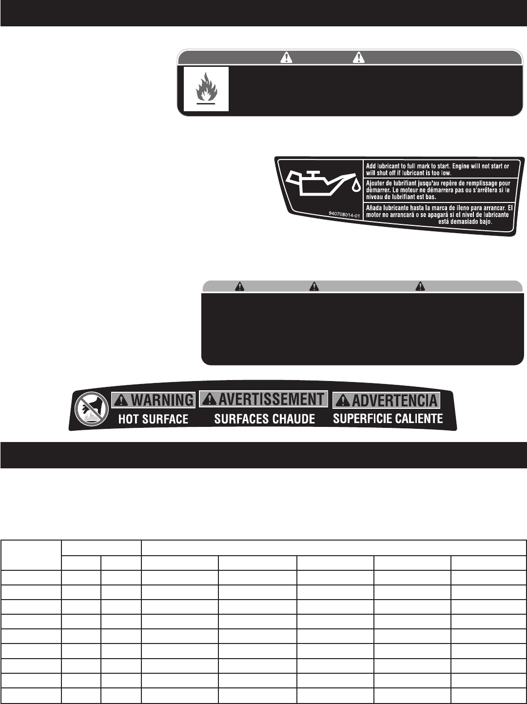
7 — Español
SÍMBOLOS
ADVERTENCIA DE COMBUSTIBLE
Nofumealabastecerelcombustible.
No llene de más. El nivel de lleno
es25,4mm (1po)debajodelcuello
del tanque de combustible. Pare la
marchadelmotorcincominutosantes
delreabastecimientodecombustible
paraevitarqueelcalordelsilenciador
enciendalosvaporesdecombustible.
ADVERTENCIA DEL LUBRICANTE DE MOTOR
Antesdeutilizarelgeneradordebeabastecerlodelubricante.El
tanquedeaceitetieneunacapacidadde13,5oz(0,42cuartos).
Antesdeutilizarlaunidad,reviseelniveldelubricante.Elnivelde
lubricantesiempredebeestarentrelasáreascubiertaconrayas
entrecruzadasdelavarilladenivel.Launidadestáequipadade
unsensor,elcualapagaautomáticamenteelmotorsielnivelde
lubricantedesciendeabajodellímitedeseguridad.
ADVERTENCIA ACERCA DE LA CONEXIÓN A TIERRA
ElReglamentoNacionaldeElectricidadexigequeelgeneradorestéconectadoaunatierraaprobada.
ADVERTENCIA DE SUPERFICIE CALIENTE
No toque el silenciador ni el cilindro de
aluminiodelmotor.EstánmuyCALIENTES
y causan quemaduras graves. No ponga
ningún material inflamable o combustible
directamente en la trayectoria de las
emanaciones del escape.
Product does not include ground rod or copper wire. National Electric Code requires generator to be
properly grounded to an approved earth ground. Call an electrician for local grounding requirements.
Le produit ne comprend pas de piquet de terre ou de fil en cuivre. Le code electrique americain (National
Electric Code) requiert un générateur pour une bonne mise à la terre approuvée. Appeler un électricien
pour connaître les exigences locales de mise à la terre.
El producto no incluye el alambre de cobre ni la barra de conexión a tierra. Los Reglamentos Nacionales
de Electricidad exigen que el generador esté debidamente conectado a una tierra aprobada.
Comuniquese con un electrista para todo lo relacionado con los requistos de conexión a tierra.
WARNING ADVERTENCIA
AVERTISSEMENT
940513008-02
ASPECTOS ELÉCTRICOS
CALIBRE DEL CORDÓN DE EXTENSIÓN
Consulteelcuadromostradoabajoparaasegurarsedequeelcalibredeloscordonesdeextensiónqueutilicepuedanconlacarga
eléctricarequerida.Loscordonesdecalibreinsuficientepuedencausarunacaídadevoltaje,locualpuedequemareldispositivoy
recalentar el cordón mismo.
Corriente en
Amperios
Carga en vatios Longitud máxima permitida del cordón
A 120 V A 240 V Conduct. #8 Conduct. #10 Conduct. #12 Conduct. #14 Conduct. #16
2,5 300 600 305m(1000pies) 183m(600pies) 114m(375pies) 76m(250pies)
5 600 1200 152m(500pies) 91m(300pies) 61m(200pies) 38m(125pies)
7,5 900 1800 107m(350pies) 61m(200pies) 38m(125pies) 31m(100pies)
10 1200 2400 76m(250pies) 46m(150pies) 31m(100pies) 15m(50pies)
15 1800 3600 46m(150pies) 31m(100pies) 20m(65pies)
20 2400 4800 53m(175pies) 38m(125pies) 23m(75pies)
25 3000 6000 46m(150pies) 31m(100pies)
30 3600 7200 38m(125pies) 20m(65pies)
40 4800 9600 27m(90pies)
Risk of Fire. Check for any fuel overflow or leaking. Stop the engine before refueling.
DANGER PELIGRO
Risque d’incendie. Vérifier l'absence de débordement ou de fuite de carburant.
Arrêter le moteur avant de fair le plein.
Riesgo de incendio. Revise si hay algún derrame o fuga de combustible. Apague el
motor antes de poner combustible. 940974007-03
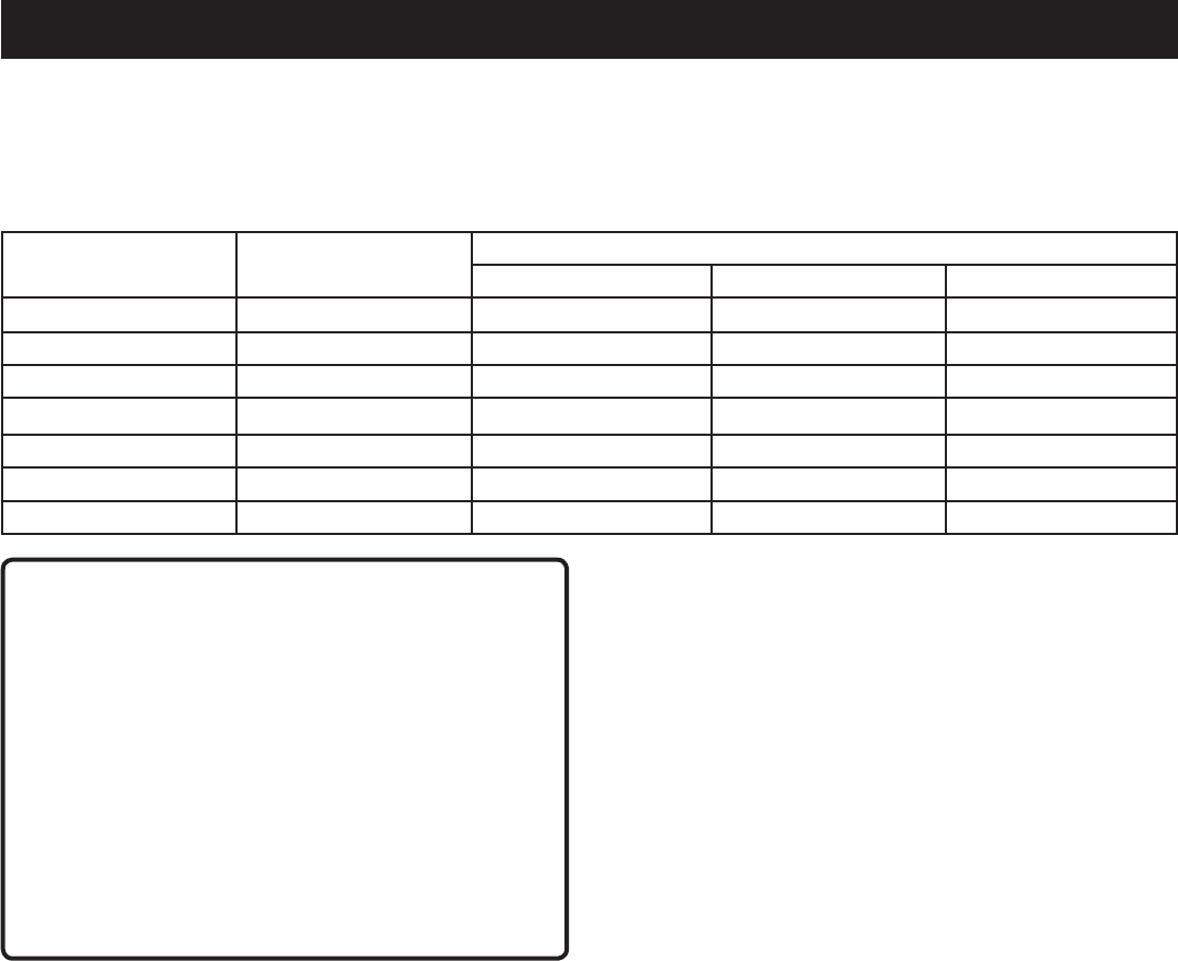
8 — Español
ASPECTOS ELÉCTRICOS
CARGAS DE MOTORES ELÉCTRICOS
Escaracterísticoenelfuncionamientonormaldelosmotoreseléctricoscomunesconsumirduranteelarranquehastaseisvecessucorriente
deoperación.Estatablapuedeemplearseparaestimarlapotencianecesaria(envatios)paraarrancarlosmotoreseléctricosde“Código
G”;noobstante,siunmotoreléctriconoarrancaonoalcanzalavelocidaddefuncionamiento,apagueeldispositivooherramientade
inmediatoparaevitardañarelequipo.Siempreverifiquelosrequisitosdelaherramientaoaparatoconlasalidanominaldelgenerador.
Capacidad del motor
(H.P.)
Potencia en marcha
(vatios)
Potencia necesaria para arrancar el motor (vatios)
Inducción de repulsión Capacitor Fase dividida
1/8 275 600 850 1200
1/6 275 600 850 2050
1/4 400 850 1050 2400
1/3 450 975 1350 2700
1/2 600 1300 1800 3600
3/4 850 1900 2600 —
1 1100 2500 3300 —
PRECAUCIÓN:
El requerimiento de voltaje y frecuencia operativa de
todos los equipos electrónicos debe comprobarse antes
de enchufarlos a este generador. Pueden ocurrir daños
si el equipo no está diseñado para operar dentro de una
variacióndevoltajede+/-10%yunavariacióndefrecuencia
de +/-3 hz de los valores nominales que aparecen en la
placadeidentificacióndelgenerador.Afindeevitardaños,
siempretengaunacargaadicionalenchufadaalgenerador
encasodeusarseequiposdeestadosólido(talescomoun
aparatodetelevisión).Tambiénpodríaresultarnecesarioun
condicionador de la línea eléctrica para algunas aplicaciones;
porejemplo,conunacomputadora.Tambiénpodriaresultar
necesario un condicionador de la línea eléctrica para algunas
aplicaciones de equipo de estado sólido.
INTERRUPTOR DE CIRCUITO ACCIONADO
POR FALLA DE CONEXIÓN A TIERRA
Vea la figura 1.
Losreceptáculos(20A,120 V)delgenerador estánprotegidos
con un interruptor de circuito accionado por falla de conexión a
tierra(GFCI),elcualprotegecontralospeligrosdelascorrientes
desarrolladasalpresentarsetalfalla.Unejemplodeunacorriente
debidaaunafalladeconexiónatierraeslaquefluiríaatravés
de una persona que está utilizando un aparato con aislamiento
defectuoso, y al mismo tiempo está en contacto con una tierra
eléctricacomounapartedelaplomería,suelohúmedootierra.
Los receptáculos protegidos con GFCIs no protegen contra cortos
circuitos,sobrecargasnidescargaseléctricas.
LosreceptáculosconGFCIs puedenprobarseconlosbotones
TEST[PRUEBA]yRESET[REAJUSTE].
Para efectuar una prueba:
OprimaelbotónTEST.EstodebehacersalirelbotónReset
(Reajustar).
Pararestablecerlacorriente,oprimaelbotónRESET.
Realicemensualmenteestapruebaparaasegurarsedelbuenfun-
cionamientodelGFCI.Siseguardaalaintemperieelgenerador,
sinproteccióndeloselementos,pruebeelGFCIdelreceptáculo
cadavezantesdeusarlaunidad.
CAPACIDAD DEL GENERADOR
Cercióresequeelgeneradorpuedasuministrarsuficientesvatios
depotenciacontinua(enmarcha)ydesobrecorriente(alarrancar)
paralosequiposquedeseealimentaralmismotiempo.Sigaestos
pasos sencillos.
1. Seleccionelosequiposquedeseaalimentaralmismotiempo.
2. Sume la potencia continua (en marcha) en vatios de estos
equipos. Esta es la cantidad de potencia que el generador
debeproducirparamantenerenmarchalosequipos.Observe
latabladereferenciadepotenciaenvatios,aladerecha.
3. Calculecuántapotenciainicial(alarranque)envatiosnecesitará.
La potencia inicial (en vatios) es la breve variación rápida
depotencianecesariaparaponerenmarchalosaparatoso
herramientasaccionadosconmotoreléctricocomolassierras
circularesolosrefrigeradores.Debidoaquenotodoslosmotores
arrancan al mismo tiempo, se puede calcular la potencia inicial
totalenvatiossumandosólolosequiposconelmayorvalor
de potencia inicial adicional a la potencia nominal del paso 2.
ADMINISTRACIÓN DE LA POTENCIA
A fin de prolongar la vida útil del generador y los dispositivos
acoplados, es importante tener cuidado al agregar cargas eléctricas
al generador. NO debe haber equipo alguno conectado a los
tomacorrientesdelgeneradorantesdeponerenmarchaelmotor
respectivo.Lamaneracorrectayseguradeadministrarlapotencia
del generador consiste en agregar las cargas de manera secuencial
delamanerasiguiente:
1. Sinequiposconectadosalgenerador,pongaenmarchaelmotor
delamaneraquesedescribeposteriormenteenestemanual.
2. Enchufeyactivelaprimeracarga,preferiblementelamáxima
carga que tenga.
3. Deje que se estabilice la salida del generador (el motor
marcha uniformemente y el dispositivo acoplado funciona
correctamente).
4. Enchufeyactivelasiguientecarga.
5. Nuevamente,dejequeelgeneradorseestabilice.
6. Repita los pasos 4 y 5 para cada carga adicional.
Nuncaañadamáscargasquelasquepermitalacapacidaddel
generador. Tenga especial cuidado al considerar las cargas de
sobrecorrienteenlacapacidaddelgeneradorsegúnsedescribió
anteriormente.
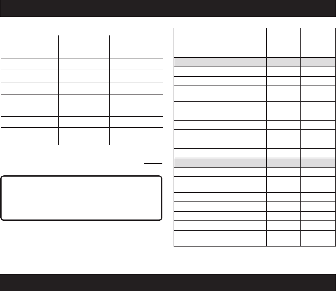
9 — Español
ASPECTOS ELÉCTRICOS
Ejemplo:
Herramienta o
aparato
Potencia continua
(enmarcha)en
vatios
Potencia inicial
(arranque)en
vatios
Refrigerador 700 1350
Ventiladorportátil 40 120
Ordenador portátil 250 250
Televisióndepantalla
plana de 116,8 cm
(46pulg.)
190 190
Luz(75Watts) 75 75
1255vatios,
potencia en
marchatotal
1350vatios,poten-
cia inicial máxima
Potenciacontinuatotalenvatios(enmarcha) 1255
Potenciainicialadicionalmáximaenvatios +1350
Potencia total de salida requerida del generador 2605
Herramienta o aparato En marcha
en vatios*
Estimado
W de
arranque*
Emergencia / En casa espera
Luz(cant.4x75W) 300 300
Refrigerador 700 1350
Televisióndepantallaplanade
116,8cm(46pulg.)
190 190
Receptor satelital 250 250
Ventiladorportátil 40 120
Calentador 1300 1300
Ordenador portátil 250 250
Olla lenta 270 270
Radio 50 50
Sitio de trabajo
Taladroeléctrico−3/8 HP 600 1000
Lámparadetrabajodehalógeno
de cuarzo
1000 1000
Sierraalternativa 960 1920
Sierracircular-184mm(7-1/4po) 1400 2300
Sierradeingletes−254mm(10po) 1800 1800
Compresordeaire−1/4HP 970 1600
Rociadordeairecomprimido−1/3
HP
600 1200
*Losvaloresdepotenciasenvatiosindicadossonaproximados.
Verifiquelapotenciarealdecadaherramientaoaparato.
PRECAUCIÓN:
Noexcedalacapacidaddelgenerador.Siexcedelacapacidad
decorriente(amperios)ypotencia(vatios)delgeneradorpuede
dañarelgeneradorylosdispositivoseléctricosconectadosal
mismo.
CARACTERÍSTICAS
ESPECIFICACIONES DEL PRODUCTO
MOTOR
Tipo de motor ..................................... Levaúnicaelevada(SOHC)
Diámetrointeriorxcarrera .................................... 88 mm x 64 mm
Sistemadeenfriamiento..............................................Aire forzado
Relación de compresión .........................................................8.5:1
Sistemadearranque .........................................................Retráctil
Sistemadeignición ................................................................T.C.I.
Bujía.................................................................... NHSPLDA7RTC
Volumendeaceitedemotor ............................ 0,39l(0,42quarts)
Volumendecombustible ......................................... 3,79l(1,0gal)
GENERADOR
Voltajenominal .............................................. 120VC.A/12VC.C.
Amperajenominal.......................................13,33 A C.A/7,5A C.C.
Potenciaenmarcha ..........................................................1 600 W
Potencia de arranque ........................................................2 000 W
Frecuencia nominal ...............................................................60 Hz

10 — Español
FAMILIARÍCESE CON EL GENERADOR
Vea la figura 2.
El uso seguro que este producto requiere la comprensión
de la información impresa en el producto y en el manual del
operadorasícomociertosconocimientossobreelproyectoa
realizar. Antes de usar este producto, familiarícese con todas
las características de funcionamiento y normas de seguridad.
RECEPTÁCULOS DE 120 V, C.A.
El generador incorpora las dos siguientes tomas monofásicas
receptáculosde60Hzqueson120Vy20Adecorriente
alterna con GFCI. Los receptáculos pueden utilizarse para
accionarlosaparatos,iluminacióneléctrica,herramientas
y motores apropiados.
FILTRO DE AIRE
Elfiltrodeaireayudaalimitarlacantidaddetierraypolvo
que penetra a la unidad durante el funcionamiento.
INTERRUPTOR DE RALENTÍ AUTOMÁTICO
El interruptor de ralentí automático se utiliza para controlar la
velocidaddelmotoryconservarelcombustible.Cuandoel
interruptor está en la posición de ENCENDIDO (I)ynohay
ningúnartefactoconectadoalaunidad,elmotorseralentiza.
Siseagregaunartefacto,lavelocidaddelmotoraumentará
hastaalimentarlaunidad.Siseextraeelartefacto,elmotor
volveráaralentí.
CABLE PARA CARGAR BATERÍAS
Utiliceelcableparacargarbateríasparaconectarbaterías
deplomo-ácidode12Vconelgenerador.
NOTA:Utilicesolamenteelcableparacargarbateríaspara
cargarbateríashúmedasdeácidodeplomoventiladas.
MANGO DE ACARREO
El generador tiene un mango de acarreo para facilitar el
transporte.
PALANCA DEL ANEGADOR
La palanca del anegador se emplea al arrancar el motor.
DISYUNTOR DE CIRCUITO DE C.C.
El disyuntor se proporciona para proteger al generator contra
sobrecargaeléctrica.
PRISE DE C.C.
Sugeneradortieneunreceptáculodecorrientecontinuade
12Vy7,5Aparacargarbateríasdeácidodeplomo.
ADVERTENCIA:
El receptáculo de CC de 12 V está diseñado para
cargarbateríashúmedasdeácidodeplomoventiladas
solamente. Otros tipos de baterías pueden explotar y
causar daños o lesiones corporales.
INTERRUPTOR DE ENCENDIDO Y APAGADO
El interruptor de encendido y apagado se utiliza en
combinaciónconelarrancadorretráctilparaarrancardel
motor. Además se utiliza para apagar del motor.
TANQUE DE COMBUSTIBLE
Eltanque de combustible tieneunacapacidad de 3,79 l
(1,0gal).
NOTA: El combustiblecirculadesde eltanque de
combustiblehastaelcarburadorsólocuandoelinterruptorde
encendido/apagado está en la posición de ENCENDIDO(I).
TERMINAL DE CONEXIÓN A TIERRA
El terminal de conexión a tierra se utiliza para ayudar a
conectar a tierra correctamente el generador como ayuda
de protección contra descargas eléctricas. Consulte con un
electricista local con respecto a los requisitos de conexión
a tierra en el área geográfica donde se encuentre usted.
VISOR DE DIODOS LUMINISCENTES
Los diodos luminiscentes indican si el generador está en
uso,estásobrecargadoosinecesitalubricante.
TAPA DE ACEITE/VARILLA PARA MEDIR EL
ACEITE
Retire la tapa de aceite/varilla para medir el aceite para
revisarel nivelyañadir lubricante al motorcuandosea
necesario.
MANGO RETRÁCTIL
El generador está equipado con un mango retráctil que
puedeajustarseparaelalmacenamientoyeltransporte.
ARRANCADOR RETRÁCTIL
Con un tirón del arrancador retráctil se arranca el motor.
TAPA DE COMBUSTIBLE VENTEADA
Elgeneradortieneunatapadecombustibleconunarejilla
que puede abrirse y cerrarse. Durante el funcionamiento
normal,larejilladebeestarenlaposiciónabierta.
CARACTERÍSTICAS
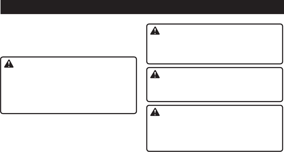
11 — Español
ARMADO
DESEMPAQUETADO
Embarcamosesteproductocompletamentearmado.
Extraigacuidadosamentedelacajalaherramientaylos
accesorios.Asegúresedequeesténpresentestodoslos
artículos enumerados en la lista de empaquetado.
ADVERTENCIA:
Noutiliceesteproductosialgunapiezaincluidaenlalista
deempaquetadoyaestáensambladaalproductocuando
lodesempaqueta.Elfabricantenoensamblalaspiezas
deestalistaenelproducto.Éstasdebenserinstaladas
porelusuario.Elusodeunproductoquepuedehaber
sido ensamblado de forma inadecuada podría causar
lesionespersonalesgraves.
Inspeccione cuidadosamente la unidad para asegurarse
quenohayasufridoningunaroturaodañoduranteel
transporte.
Nodesecheelmaterialdeempaquetadohastaquehaya
inspeccionado cuidadosamente el producto y lo haya
utilizado satisfactoriamente.
Sihaypiezasdañadasofaltantes,lesuplicamosllamaral
1-800-860-4050,dondelebrindaremosasistencia.
LISTA DE EMPAQUETADO
Generador
Cableparacargarbaterías
Lubricantedemotor(SAE10W30)
Mangodeeje
Llaveparabujía
Manual del operador
ADVERTENCIA:
Si falta o está dañada alguna pieza, no utilice este
producto sin haber reemplazado la pieza. Usar este
producto con partes dañadas o faltantes puede causar
lesiones serias al operador.
ADVERTENCIA:
No intente accionar el generador antes de terminar
dearmarlo.Delocontrariopuedeocurrirunriesgode
lesionesgraves.
ADVERTENCIA:
No intente modificar esta producto ni introducir
accesorios no recomendados para la misma. Cualquier
alteración o modificación constituye maltrato y puede
causar una condición peligrosa, y como consecuencia
posibleslesionescorporalesgraves.
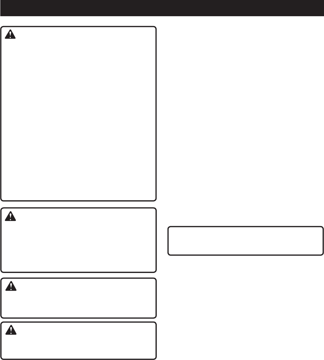
12 — Español
FUNCIONAMIENTO
PELIGRO:
Monóxido de carbono. Usar un generador en el interior LO
MATARÁENPOCOSMINUTOS.
Losgasesdeescapedelgeneradorcontienennivelesaltos
demonóxidodecarbono(CO),ungasvenenosoqueno
puedeverseniolerse.Sipuedeolerlosgasesdeescape
del generador, está respirando CO. Pero incluso si no puede
olerlosgasesdeescape,esposiblequeestérespirandoCO.
Nuncauseungeneradordentrodesuhogar,garaje,
sótano, ni demás espacios parcialmente encerrados. En
dichosespacios,puedenacumularsenivelesmortales
demonóxidodecarbono.Usarunventiladoroabrir
puertas y ventanas NO proporciona suficiente aire
fresco.
SÓLOutiliceelgeneradoralairelibreylejosdeventanas,
puertas y respiraderos abiertos. Estas aberturas
pueden atraer los gases de escape del generador.
Incluso si utiliza el generador correctamente, el CO puede
ingresarensuhogar.SIEMPREutiliceunaalarmadeCOde
pilasoconpilasderespaldoensuhogar.
Si comienza a sentirse descompuesto, mareado o débil
luegodequeelgeneradorestuvofuncionando,trasládese
adondehayaairefrescoINMEDIATAMENTE.Veaaundoctor.
Puedesufririntoxicaciónpormonóxidodecarbono.
PELIGRO:
El incumplimiento de conectar correctamente a tierra el
generador puede resultar en electrocución, especialmente
sielgeneradorestáequipadoconunconjuntoderuedas.El
ReglamentoNacionaldeElectricidadexigequeelgenerador
esté debidamente conectado a una tierra aprobada.
Comuníquese con un electricista para todo lo relacionado
con los requisitos de conexión a tierra.
ADVERTENCIA:
No permita que su familiarización con este producto lo
vuelvadescuidado.Tengapresentequeundescuidodeun
instanteessuficienteparacausarunalesióngrave.
ADVERTENCIA:
Noutiliceningúnaditamentooaccesorionorecomendadopor
elfabricantedeesteproducto.Elempleodeaditamentoso
accesoriosnorecomendadospodríacausarlesionesgraves.
APLICACIONES
Este generador está diseñado para suministrar alimentación
eléctrica para el funcionamiento de iluminación eléctrica
compatible,electrodomésticos,herramientasycargasdemotor.
ANTES DE ACCIONAR LA UNIDAD
SóloutilíceloALAIRELIBREylejosdeventanas,puertasy
respiraderos.
NUNCAlousedentrodesuhogarodelgaraje,INCLUSO
conlaspuertasylasventanasabiertas.
Coloquesiempreel generador sobre una superficie firme plana.
VISOR DE DIODOS LUMINISCENTES
Vea la figura 3.
Potencia:
El indicador de potencia se encenderá cuando el generador
esté encendido y los receptáculos estén funcionando.
NOTA:Elgeneradorestásobrecargado,laluzdelindicadorde
potencia se apagará.
Sobrecarga:
El indicador de sobrecarga se encenderá si se supera la
capacidaddeamperajeyvatajedelgenerador.Silasobrecarga
espequeña,launidadseguiráfuncionandoconnormalidad.Sila
sobrecargaesgrande,lasalidade120Vsedesconectarápara
prevenirdañosaloscomponenteseléctricosdelgenerador.
Parareajustarelgenerador,apaguelaunidadysaquetodaslas
cargas.Elgeneradornosereajustaráamenosqueseapague
el generador.
Aceite:
Laluz debajoniveldelubricante parpadearáyelmotorse
detendráautomáticamentecuandoelniveldelubricantedelmotor
seabajo.Esposiblequeelmotornopuedaencendersehasta
que no se agregue suficiente aceite de motor en el generador.
NOTA: Es normal que las luces del indicador se enciendan
oparpadeencadavezqueseenciendaelmotor.Cuandoel
motorsehayacalentado,laslucesdebenregresardemanera
predeterminada al patrón anterior.
PRECAUCIÓN:
Siseintentaarrancarelmotorantesdehaberseabastecido
debidamentedelubricantepodríadescomponerseelequipo.
VERIFICACIÓN Y ABASTECIMIENTO DE
LUBRICANTE
Vea la figura 4.
Ellubricantedemotorempleadoesunfactordegran
importanciaenelrendimientoy vida de servicio del motor.
Para uso general, a todas temperaturas, se recomienda el
aceiteSAE10W-30.Siempreutilicelubricanteparamotorde
cuatrotiemposquesatisfagaosobrepaselosrequisitosSJde
clasificacióndeservicioAPI.
NOTA: El lubricante sin detergente opara motor de dos
tiemposdañaelmotor,porlocualnodebeusarse.
Retireeltornillodelapartesuperiordelacubiertadelmotor.
Retirelacoberturayhágalaaunlado.
Desenrosquelatapaderellenodeaceite/varillamedidora
de aceite y retírela.
Limpielavarilladenivelyvuelvaaasentarlaenelagujero;
no la enrosque.
Retiredenuevolavarillamedidoradelubricanteyverifique
elniveldelubricante.Elniveldelubricantedebeestarentre
lasmarcasmínimaymáximaenlavarillamedidora.
Sielnivelestábajo,agreguelubricanteparamotorhasta
queelniveldefluidoseencuentreentrelasmarcasmínima
ymáximaenlavarillamedidora.
Vuelvaacolocarlatapaderellenodeaceite/varillamedidora
deaceiteyasegúrela.
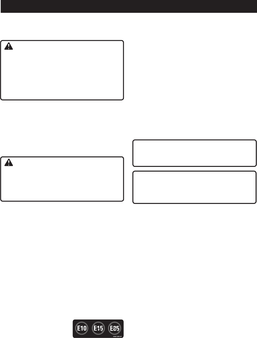
13 — Español
FUNCIONAMIENTO
VERIFICACIÓN Y ABASTECIMIENTO DE
COMBUSTIBLE
Vea la figura 5.
ADVERTENCIA:
Lagasolinaesextremadamenteinflamableyexplosiva.Un
incendio o una explosión de gasolina le causará quemaduras
a usted y a otras personas. Apague siempre el motor antes
decargarcombustible.Nuncaagreguecombustibleauna
máquinaconelmotorenmarchaocaliente.Aléjesealmenos
a9metros(30pies)dellugardonderecargóelcombustible
antesdeencenderelmotor.Nofumeyaléjesedelasllamas
abiertasylaschispas.Sinomanipulaelcombustiblede
manerasegura,puedesufrirlesionespersonalesgraves.
Retirelatapadecombustible.
Lleneel tanque de combustiblehasta una altura de
25,4mm(1po)abajodelcuellodeltanque.
Coloquedenuevolatapadeltanquedecombustibleyajuste
hastaqueescucheunclic.
NOTA: Siempreutilicegasolinasin plomocon un octanaje
nominalinicialde86 o mayor.Nunca utilice gasolina vieja,
pasada o contaminada, y no utilice mezcla de aceite y gasolina.
Nopermitaqueentretierraoaguaeneltanquedecombustible.
No use combustible E85.
ADVERTENCIA:
Reviselaherramientaparaversitienefugasdecombustible.
Unatapadeltanquedecombustibleconfugasconstituye
unriesgodeincendioydebereemplazarseinmediatamente.
Siencuentrafugas,corrijaelproblemaantesdeutilizarla
herramienta.Delocontrariopuedeproducirseunincendio,
con el consiguiente riesgo de lesiones serias.
USO DE ESTABILILZADOR DE COMBUSTIBLE
Elcombustiblesehaceviejo,seoxidaydescomponealpaso
del tiempo. Agregando estabilizador de combustible (no
incluido)seprolongalavidaútildelcombustibleyseevitala
formación de depósitos, los cuales pueden tapar el sistema
delcombustible.Sigalasinstruccionesdelfabricantedel
estabilizadordecombustibleencuantoaladebidaproporción
estabilizador-combustible.
Viertael estabilizador en el tanque de combustible y,
después, llénelo de gasolina de conformidad con las
instrucciones anteriores.
NOTA: Puedenmezclarseelestabilizadorylagasolinaantes
de llenar el tanque; para ello utilice una lata de gasolina u otro
recipienteaprobadoparacombustibleyagítelasuavemente
para realizar la mezcla.
Coloquedenuevolatapadel tanque de combustible y
asegúrela.
Arranqueelmotorydéjelofuncionarporlomenoscinco
minutosparapermitirque el estabilizador trate todo el
sistemadecombustible.
COMBUSTIBLES OXIGENADOS
NO UTILICE COMBUSTIBLES E15
O E85 EN ESTA UNIDAD. ESTO
CONSTITUYE UNA VIOLACIÓN
A LA LEY FEDERAL, DAÑARÁ LA UNIDAD Y ANULARÁ LA
GARANTÍA.
NOTA: No están cubiertos en la garantíalosproblemasde
desempeñoodañosalsistemadecombustibleproducidos
poreluso de un combustible oxigenado con un contenido
superioralosporcentajesde alcohol o compuesto de éter
señaladosabajo.
Etanol.Lasgasolinasconuncontenidode10%deetanolpor
volumen(comunmenteconocidacomoE10)esaceptables.Las
gasolinas E15 y E85 no lo son.
ABERTURA Y CIERRE DE LA TAPA DE
COMBUSTIBLE VENTEADA
Vea las figuras 6 - 7.
Elgeneradortieneunatapadecombustibleconunarejillaque
puedeabrirseycerrarse.
Paraabrirlarejilla,girelapalancadelatapadecombustible
hastalaposiciónON (I).Larejilladebeestarabiertadurante
el funcionamiento.
Paracerrarlarejilla,girelapalancadelatapadecombustible
hastala posición OFF (O). La rejilla debe estar cerrada
cuando el generador no esté en uso.
PRECAUCIÓN:
Teniendolaunidadenunasuperficieniveladayconelmotor
apagado,reviseelnivelde lubricantecada vezantes de
usar el generador.
PRECAUCIÓN:
Nocoloqueelgeneradordirectamenteenelpisocuando
uselaunidadenáreascubiertasdehierbasoconmucha
vegetación.Sihaceeso,podríaocasionarunadecoloración
del pasto y daño de suelo localizado.
ARRANQUE DEL MOTOR
Vea las figuras 8 a 11.
NOTA: Sielgeneradornoestáenunasuperficienivelada,es
posiblequenoarranqueoseapaguedurantesufuncionamiento.
Desconectetodaslascargasdelgenerador.
Coloque el interruptor de ralentí automático en la posición
de APAGADO.
Abralarejilladelatapadelcombustiblegirandolapalanca
delatapadecombustiblehastalaposiciónON (I).
Lleveelinterruptordelencendidoyapagadoenlaposición
de ENCENDIDO (I).
NOTA: Cuando el interruptor de encendido/apagado está
en la posición ENCENDIDO (I),elcombustiblecirculará
desdeeltanquedecombustiblehastaelmotor.
Desplaceizquierdade la palanca del anegadorhastala
posición START(ARRANQUE).
NOTE: Sielmotorestácaliente,desplacederechalapalanca
del anegador de la posición RUN(FUNCIONAMIENTO).
Tiredelarrancadorretráctilhastaquecomienceafuncionar
elmotor(seisvecescomomáximo).
NOTA: Nopermitaqueelmangoseretraigaviolentamente
después de arrancar; regréselo suavemente a su lugar
original.
14 — Español
FUNCIONAMIENTO
Permita que el motor funcione 15 - 30 segundos y, después,
desplace izquierda la palanca del anegador en la posición
RUN(FUNCIONAMIENTO).
APAGADO DEL MOTOR
Vea las figuras 7 a 10.
Desconectedelgeneradortodacargapresente.
Lleveelinterruptordelencendidoyapagadoenlaposición
de OFF(APAGADO).
Cierrelarejilladelatapadelcombustiblegirandolapalanca
delatapadecombustiblehastalaposiciónOFF (O).
NOTA: Si la temperatura se encuentra por arriba de los
24˚C(75˚F),dejeabiertalarejillaenlatapadelcombustible
paraaliviarlapresión.
Para apagar el motor en una situación de emergencia:
Lleve el interruptor del motor a la posición de
APAGADO(O) .
UTILIZANDO EL CABLE PARA CARGAR
BATERÍAS
Vea la figura 12.
ADVERTENCIA:
ElreceptáculodeCCde12Vestádiseñadoparacargar
bateríashúmedasdeácidodeplomoventiladassolamente.
Otrostiposdebateríaspuedenexplotarycausardañoso
lesiones corporales.
PRECAUCIÓN:
ElreceptáculodeCCde12Vproporcionacargacontinua
charge.Nosobrecarguelabateríanisealejedeella.Elhacer
tanpuedecausardañoalabatería.
PRECAUCIÓN:
Nohacerarrancarvehículosconpuenteeléctrico.Elhacer
tanpodríadarlugaradañoalvehículooescomponentes
eléctricos.
Conecteelcableparacargarbateríasalabateríaconlas
pinzasparabaterías.Conecteelcablerojoconlaterminal
positiva(+)yelcablenegrocon la terminal negativa (–).
Asegúresedequetodaslasconexionesesténfirmes.
NOTA: Teniendocuidadodenocausarcortocircuitoenlas
terminales.Uncortocircuitoaljuntarlasterminalespuede
causarchispas,dañosalabateríaoalgeneradoryhasta
quemaduras o explosiones.
Conecteelcableparacargarbateríasalreceptáculode12V
Arrancar la unidad.
NOTE: Los receptáculos de CA pueden usarse mientras el
receptáculo de CC se está usando.
Elpaquetedebateríassesienteunpococalientealtocarse
mientrasestácargándose.Estoesnormalynoindicaningún
problema.
NOTA:Utilicesolamenteelcableparacargarbateríaspara
cargarbateríashúmedasdeácidodeplomoventiladas.
Despuésdelabateríaestácompletamentecargada,
desconecteelcable.Desconecteelbornenegativo(negro),
luegoelbornepositivo(rojo)concuidadodenocortocircuitar
lasterminales.Siempre observe las advertenciasde
seguridadquesesuministranconlabatería.
NOTA: Lamayoríadelasbateríassecargaráncompletamente
unaveztranscurridosentre30y120minutos.Sinembargo,
esaltamenterecomendablequeconsultelasinstrucciones
delfabricantedesubateríaparaconocerlostiemposde
carga específicos.
Desconecteelcableparacargarbateríasyalmacenar.
TRASLADO EL GENERADOR
Vea la figura 13.
Coloque el interruptor de encendido y apagado en la
posición de OFF(APAGADO).
Permita un período de enfriamiento de 30 minutos antes de
guardar la máquina.
Saqueelmangoretráctil.
Colóquese de frente a la parte posterior del generador, y
sujeteelmangoretráctilfirmementeconambasmanos.
Inclineelgeneradorhaciaustedhastaquesesostengasobre
sus ruedas.
Gire la unidad, colóquese delante de ella y tire de ésta para
colocarla en el lugar deseado
Bajeelgeneradorhastaqueseapoyefirmementesobreuna
superficie plana.
ADVERTENCIA:
Aldarservicioalaunidad,sóloutilicepiezasderepuesto
idénticas. El empleo de piezas diferentes puede causar un
peligro o dañar el producto.
ADVERTENCIA:
Siempre póngase protección ocular con la marca de
cumplimientodelanormaANSIZ87.1.Lainobservanciade
estaadvertenciapuedepermitirquelosobjetoslanzados
hacialosojospuedanprovocarlelesionesgraves.
MANTENIMIENTO
MANTENIMIENTO GENERAL
Mantenga el generador en un entorno limpio y seco, en el
cualnoestéexpuestoalpolvo,tierra,humedad o vapores
corrosivos.Nopermitaquelasranurasdeairedeventilación
delgeneradorsetapendemateriaextraña,comohojas,etc.
Noutiliceunamangueradejardínparalimpiarelgenerador.
Elagua queentra alsistema decombustible uotraspartes
internaspuedecausarproblemasqueacortanlavidadeservicio
del generador.
15 — Español
MANTENIMIENTO
MANTENIMIENTO DE LA BUJÍA
Vea la figura 17.
Labujíadebetenereldebidoespaciointerelectródicoydebe
estarlibrededepósitosparaqueelmotorfuncionedeforma
correcta.Paraverificar:
Extraigalatapadelabujía.
Retirelatapadelabujía.
Limpietodalatierrapresentealrededordela basedela
bujía.
Retirelosbujíasconlallaveparabujía.
Inspeccionelabujíaparaversiestádañada,ylímpielaconun
cepillodealambreantesdevolverainstalarla.Sielaislante
estáagrietadoodesportillado,debereemplazarselabujía.
NOTA: Sivaareemplazarla,utilicelabujíarecomendadas,
ounaequivalente: NHSP LD A7RTC.
Mida el espacio interelectródico. La separación correcta
es0,60-0,70mm(0,024−0,028pulg.).Paraampliarla
separación, doble con cuidado el electrodo (superior)
de conexión a tierra. Para angostar el espacio, golpee
suavementesobreunasuperficieduraelelectrododetierra.
Asienteensulugarlabujíayenrósquelaconlamanopara
evitartrasroscarla.
Apriételaconunallaveparacomprimirlaarandela.Sies
nuevalabujía,gírela1/2 vuelta para comprimir al nivel
adecuadolaarandela.Sivaavolverausarlabujíavieja,
gírelade1/8a1/4devueltaparacomprimiralniveladecuado
la arandela.
NOTA: Sinoseaprietadebidamente,labujíasecalienta
muchoypodríadañarelmotor.
PRECAUCIÓN:
Tengacuidadodenoenroscardeformacruzadalabujía.Si
haceeso,elproductosedañarágravemente.
DRENAJE DEL TANQUE DEL COMBUSTIBLE
Y DEL CARBURADOR
Vea las figuras 18 y 19.
Paraevitarlosdepósitosdesustanciasgomosasenelsistema
decombustible,vacíeeltanquedecombustibleyelcarburador
antes de guardarlo.
Drenaje del tanque de combustible
PRECAUCIÓN:
Extraigatodoellubricantedelaunidadantesdedrenarel
tanquedecombustible.Sinohaceesto,launidadpodría
dañarse.
Retirelatapadeltanquedecombustible.
Para limpiar la unidad:
Conuncepillodecerdassuavesy/ounaaspiradoraafloje
yeliminelatierraylabasura.
Limpielasaberturasdeventilaciónconaireabajapresión
que no se exceda de 25 psi.
Limpie las superficies exteriores del generador con un paño
húmedo.
REVISIÓN Y LIMPIEZA DEL FILTRO DE AIRE
Vea las figuras 14 y 15.
Paraobtenerundesempeñoapropiadoyunalargavidaútilde
la unidad, mantenga limpios los filtro de aire.
Retireeltornillodelapartesuperiordelacubiertadelmotor.
Retirelacoberturayhágalaaunlado.
Retire el tornillo que está en el centro de la tapa del filtro de
aire.Retirelatapadelfiltrodeaireyhágalaaunlado.
Extraiga el filtro de aire grande y pequeño.
Laveelfiltrodeaireconaguajabonosatibia.Enjuágueloy
estrújeloparasecarlo.
Vuelvaainstalarlafiltrodeaire.
NOTA: Asegúresede quelosfiltrosesténcorrectamente
colocados dentro del generador. La instalación incorrecta
delosfiltrosharáqueingresesuciedadalmotoryqueéste
se desgaste rápidamente.
Vuelvaainstalarlatapadelfiltrodeaire.Aprieteeltornillo
para asegurarla.
Vuelvaainstalarlacoberturademotor.Aprieteeltornillo
para asegurarla.
CAMBIO DE ACEITE DE MOTOR
Vea la figura 16.
Paralograr undesempeñoóptimo, ellubricantepara motor
debecambiarsecada100horaso6mesesdeuso.
Retireeltornillodelapartesuperiordelacubiertadelmotor.
Retirelacoberturayhágalaaunlado.
Retireeltapóndedrenajedelaceiteydreneelaceiteviejo.
Inclineelgeneradorparapermitirqueellubricantedrenepor
elagujerodellenadodeaceiteenuncontenedoraprobado.
NOTA: Drene el aceite mientras esté tibio el motor, no
caliente.Elaceitetibiosedrenacon mayor facilidad y
compleción.
Vuelva a colocar el generadoren unaposiciónrectay
reabastezcadelubricante launidaddeconformidadcon
las instrucciones indicadas en el apartado Verificación y
abastecimiento de lubricante.
Vuelvaacolocarlatapaderellenodeaceite/varillamedidora
deaceiteyasegúrela.
Vuelvaainstalarlacoberturademotor.Aprieteeltornillo
para asegurarla.
NOTA: El lubricante usado debe desecharse en un sitio de
desechoaprobado.Sinecesitamásinformación,consultea
un concesionario de aceite de la localidad.
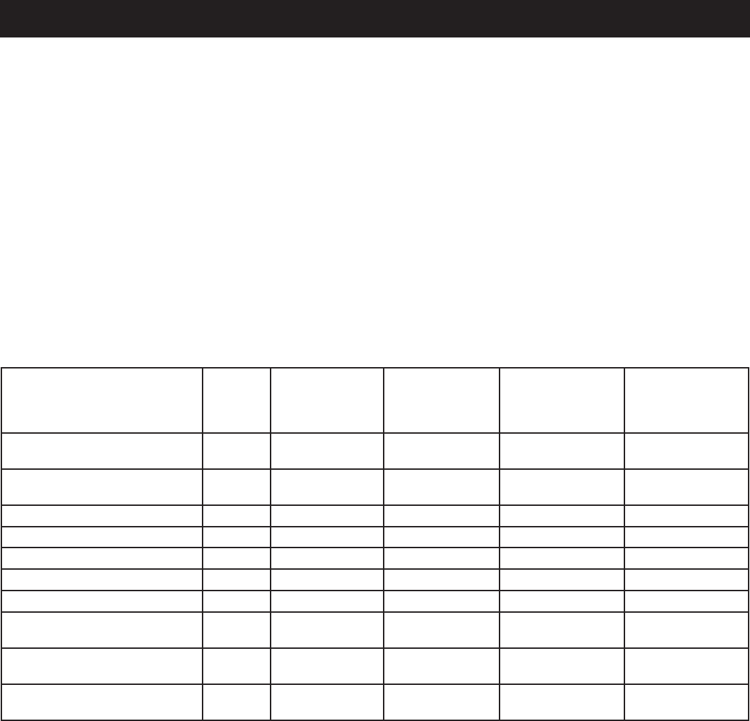
16 — Español
MANTENIMIENTO
PROGRAMA DE MANTENIMIENTO
NOTA: Sirecibeunmanualdelmotorparaestegeneradorenparticular,respeteelcronogramademantenimientoqueseindique
en el manual del motor y no la información de mantenimiento que figura a continuación.
Antes de
cada
uso
Al cabo del
primer mes o 10
horas de funcio-
namiento
Cada 3 meses
o 50 horas de
funcionamiento
Cada 6 meses
o 100 horas de
funcionamiento
Cada año o luego
de 300 horas
de funciona-
miento
Revisar el lubricante del
motor
Cambiar el lubricante del
motor
Revisar el filtro de aire
Limpiar el filtro de aire2
Cambiar el filtro de aire2
Comprobar/ajustar la bujía
Reemplazar la bujía2
Comprobar/ajustar el huelgo
de válvula1,2
Limpiar el depósito y el filtro
de combustible1
Comprobar el tubo de
combustible
1.Estastareasdebenserefectuadassóloporelcentrodeservicioautorizado.
2. Consulte el manual del motor para conocer el cronograma de mantenimiento de este elemento.
NOTA: Lafrecuenciademantenimientodebesermayorsiseelgeneradorseusaenzonasdemuchopolvo.
Sielgeneradorhasobrepasadolosvaloresmáximosespecificadosenelcuadro,aundebeseguirseelprogramade
mantenimientodeacuerdoconlosintervalosallírecomendados.
Inclineelgeneradorparapermitirqueelcombustibledrene
poreltanquedecombustibleenuncontenedoraprobado.
Unavezquesehayadrenadotodo el combustible del
tanque,reemplacelatapadeltanquedecombustible.
Drenaje del carburador
Lleveelinterruptordelencendidoyapagadoenlaposición
de ENCENDIDO(I).
Retireeltornillodelapartesuperiordelacubiertadelmotor.
Retirelacoberturayhágalaaunlado.
Coloqueunrecipienteadecuadobajoeltornillodedrenaje
delcarburadorpararecibirelcombustible;aflojeeltornillo.
Permitaquesedrenecompletamenteelcombustibleycaiga
en el recipiente.
Vuelvaaapretareltornillodedrenaje.
Lleveelinterruptordelencendidoyapagadoenlaposición
de OFF(APAGADO).
NOTA: Consultelasnormasdedesechoderesiduospeligrosos
delalocalidaddondeseencuentrepara averiguar la forma
correctadedesecharelcombustibleusado.
TRANSPORTE
Coloque el interruptor de encendido y apagado en la
posición de OFF(APAGADO).
Asegúresede queestén fríosel motoryelescapedela
unidad.
Altransportarlaunidad,manténgalanivelada paraevitar
quesederramecombustible.
Nodejecaerla unidad, no la golpee ni la coloque bajo
objetospesados.

17 — Español
CORRECCIÓN DE PROBLEMAS
PROBLEMA CAUSA POSIBLE SOLUCIÓN
El motor no arranca. El encendido y apagado está en
APAGADO (O).
Nohaycombustibleeneltanque.
Estábajoelniveldelubricante.
Bujíadefectuosa,suciaoconseparación
incorrecta.
La palanca de anegador está en la
posición RUN(FUNCIONAMIENTO).
El motor almacenado sin tratamiento ni
vaciadodegasolina,oreabastecidode
gasolina de mala calidad.
Elementodecombustibleobstruidos.
Ponga el encendido y apagado está en
ENCENDIDO (I).
Llene el tanque.
Reviseelniveldellubricantedelmotor,y
reabastézcalosiesnecesario.
Reemplacelabujía.
Desplaceizquierdade la palanca del
anegador hasta la posición START
(ARRANQUE).
Vacíe el combustible y el carburador.
Reabastezcadegasolinafrescalaunidad.
Comuníqueseconuncentrodeservicio
autorizado.
Le falta potencia al motor. El motor almacenado sin tratamiento ni
vaciadodegasolina,oreabastecidode
gasolina de mala calidad.
Está sucio el filtro de aire.
Vacíeelcombustibleyelcarburador.Rea-
bastezcadegasolinafrescalaunidad.Si
elproblemacontinúa,comuníquesecon
uncentrodeservicioautorizado.
Limpieoreemplacesegúnseanecesario.
NofuncionaelreceptáculodeC.C. Disjoncteurdéclenché
Estádefectuosoeldispositivoconectado.
Débrancher toutes les charges du
générateur. Régler l’interrupteur du
moteuràlaposition«OFF»(O)(arrêt),
puisappuyersurledisjoncteurc.c.Voir
la figure 20.
Pruebeconundispositivodiferente.
NofuncionaelreceptáculodeC.A. Estádefectuosoeldispositivoconectado. Pruebeconundispositivodiferente.
Sielproblemapersistedespuésdeprobarlassolucionesmencionadasarriba,comuníqueseconuncentrodeservicioautorizado
para solicitar asistencia.
Lossiguientessíntomaspuedenindicarproblemasqueafectanelniveldeemisionesdelaunidad:
Arranque difícil o paro del motor después de arrancar
Marchalentairregular
Fallaoretardoenlacombustión,conlaunidadbajocarga
Combustiónsecundaria(combustiónretardada)
Salehumonegrodelescapeoconsumoelevadodecombustible
Siencuentracualquieradeestossíntomas,permitaqueinspeccionenyreparenlaunidadenuncentrodeservicioautorizado.

18 — Español
GARANTÍA
DERECHOS Y OBLIGACIONES DE SU GARANTÍA
LaAgenciadeProtecciónAmbientaldelosEstadosUnidos(EPA)yYongkang Zhongjian Tools Manufacture Co.,
Ltd (Zhongjian)secomplacenenexplicarlagarantíadelsistemadecontroldeemisionesdesunuevoypequeño
motortodoterreno.Losnuevosypequeñosmotorestodoterrenodebendiseñarse,fabricarseyequiparsepara
cumplir con los estrictos estándares antiesmog de la EPA. Zhongjiandebegarantizarelfuncionamientodelsistema
de control de emisiones de su motor pequeño todo terreno por los períodos de tiempo que figuran a continuación,
siemprequeelmotornohayasufridomaltratos,negligencia,niselehayanrealizadomodificacionesinapropiadas
o un mantenimiento inadecuado.
Susistemadecontroldeemisionespuedeincluirpiezascomolassiguientes:carburador,sistemadeencendido,los
sistemasdeentradaysalida,yotroscomponentesrelacionados.Encasodequesepresenteunacondicióncubierta
por la garantía, Zhongjian reparará su motor sin costo alguno por el diagnóstico, el reemplazo de las piezas y la
manodeobra.
COBERTURA DE LA GARANTÍA DEL SISTEMA DE CONTROL DE EMISIONES DEL FABRICANTE:
Como se detalla a continuación, los sistemas de control de emisiones de los motores modelo 2011 y posteriores
estáncubiertosporunagarantíadedosaños.Sisecompruebaque,duranteesteperíododegarantía,algúnsistema
ocomponentedelmotorrelacionadoconlaemisióntienedefectosenmaterialymanodeobra,unCentrodeservicio
de garantía autorizado de Zhongjian realizará las reparaciones o los reemplazos correspondientes.
RESPONSABILIDADES DEL COMPRADOR/PROPIETARIO CON RESPECTO A LA GARANTÍA:
Comocomprador/propietariodelpequeñomotortodoterreno,ustedesresponsablederealizartodoslosserviciosde
mantenimientorequeridosquefiguranenelManualdelpropietarioprovistoporelfabricante.Afinesdelagarantía,
Zhongjianlerecomiendaqueconservetodoslosrecibosdelosserviciosdemantenimientodesumotor.Sinembargo,
Zhongjiannopuedenegarlaprestacióndelserviciodegarantíasolamenteporqueustednotengalosreciboso
porquenohayarealizadotodoslosmantenimientosprogramados.
Noobstante,comocomprador/propietariodelpequeñomotortodoterreno,tengaencuentaqueZhongjian puede
negarunapartey/otodalacoberturaolaresponsabilidaddelagarantíasielmotorounadesuspiezasocomponentes
fallacomoresultadodeabuso,negligencia,mantenimientoinadecuado,modificacionesinapropiadasoporelusode
piezasfalsificadasuobtenidasdel“mercadogris”queZhongjiannohafabricado,suministradoniaprobado.
UstedesresponsabledepresentarsumotorenunestablecimientodeservicioautorizadoporlagarantíadeZhongjian
encuantosepresenteunproblema.Lasreparacionescubiertasporlagarantíadebenrealizarsedentrodeunlímite
detiemporazonablequenopuedeexcederlos30días.
Pararecibirelserviciodegarantía,comuníqueseconsuvendedoroconunestablecimientodeservicioautorizado
porlagarantíadeZhongjian.ParabuscarelestablecimientodeservicioautorizadoporlagarantíadeZhongjian más
cercano, llame al 1-800-860-4050.
GARANTÍA DE EMISIONES SEGÚN LA AGENCIA DE PROTECCIÓN AMBIENTAL (EPA)

19 — Español
GARANTÍA
SUS DERECHOS Y OBLIGACIONES EN RELACIÓN
CON LA GARANTÍA
LaJuntadeRecursosdelAiredeCalifornia(CARB)yYongkang
ZhongJian Tools manufacture Co., Ltd. se complacen en
explicarle la garantía del sistema de control de emisiones de
sumotorpequeñoparausofueradecarreteras(SORE)modelo
2011 o posterior. En California, los SOREs nuevos deben
diseñarse,fabricarseyequiparsedemaneraquecumplancon
las rigurosas normas estatales contra la contaminación del
aire.YongkangZhongJianToolsmanufactureCo.,Ltd.debe
garantizarelsistemadecontroldeemisionesdesuSOREen
los períodos de tiempo que se indican a continuación, siempre
queelSOREnohayasufridounusoincorrecto,negligenciao
mantenimiento inadecuado.
El sistema de control de emisiones puede incluir partes como
elcarburador,lostanquesdecombustible,lostaponesdelos
tanquesdecombustible,laslíneasdecombustible,elsistema
deencendidoyelcatalizador.Tambiénpuedeincluirmangueras,
correas,abrazaderas,conectoresyotrosmontajesrelacionados
con las emisiones.
Cuando se presente una situación contemplada por la garantía,
YongkangZhongJianToolsmanufactureCo.,Ltd.repararásu
motor pequeño para uso fuera de carreteras sin costo, incluyendo
eldiagnóstico,laspartesylamanodeobra.
COBERTURA DE LA GARANTÍA DEL FABRICANTE:
El sistema de control de emisiones está garantizado por dos años.
Sicualquierpartedesumotorrelacionadaconlasemisiones
estádefectuosa, dichaparte seráreparadaocambiadapor
YongkangZhongJianToolsmanufactureCo.,Ltd.
RESPONSABILIDADES DEL PROPIETARIO EN
RELACIÓN CON LA GARANTÍA:
ComopropietariodelSORE,ustedesresponsabledeque
serealiceelmantenimientoobligatorioqueindicaelmanual
delpropietario.YongkangZhongJianToolsmanufactureCo.,
Ltd. le recomienda que guarde todos los comprobantes
relacionadosconelmantenimientode suSORE,aunque
YongkangZhongJianToolsmanufactureCo.,Ltd.nopuede
rechazarlagarantía porelsólohechode queusted sea
incapazdepresentardichoscomprobantesoasegurarla
realización de todo el mantenimiento programado.
Sinembargo,comopropietariodelSORE,debeteneren
cuentaqueYongkangZhongJianToolsmanufactureCo.,Ltd.
puederechazarlacoberturadegarantíasisuSOREouna
desuspartesfallódebidoalusoincorrecto,lanegligencia,el
mantenimiento inadecuado o la realización de modificaciones
noaprobadas.
Ustedesresponsablede llevarsuSORE auncentrode
distribuciónodemantenimientoautorizadoporYongkang
ZhongJianToolsmanufactureCo.,Ltd.tanprontocomose
presenteelproblema.Lasreparacionesamparadasporla
garantíadebenrealizarseenunplazorazonable,nomayor
a 30 días.
Sitienealgunapreguntaacercadelacoberturadelagarantía,
póngase en contacto con un representante de atención al cliente
deYongkangZhongJianToolsmanufactureCo.,Ltd.,llamando
al 1-877-218-5285.
DECLARACIÓN DE GARANTÍA DEL CONTROL DE EMISIONES DE CALIFORNIA
COBERTURA DE LA GARANTÍA CONTRA DEFECTOS:
ConformealodispuestoporlaJuntadeRecursosdelAirede
California (CARB), Yongkang ZhongJian Tools manufacture
Co., Ltd. garantiza al comprador final y a cualquier comprador
sucesivoqueelmotorpequeñoparausofueradecarreteras
(SORE)(1)hasidodiseñado,construidoyequipadoparacumplir
contodaslasnormativaspertinentes;y(2)estálibrededefectos
enlosmaterialesylafabricaciónquepuedancausarlafallade
unapartebajogarantía,deacuerdoconlasnormativasquese
apliquen a los términos y condiciones indicados a continuación.
(a)Elperíododegarantíacomienzaenlafechaenlaque
el motor se entrega a un comprador final. El período de
garantía es de dos años.
(b)Sujeta a ciertas condiciones y excepciones según
seindicaacontinuación,lagarantíasobrelaspartes
relacionadas con las emisiones tiene los siguientes
términos:
(1) Cualquier parte cubierta por la garantía que no tenga
programado un cambio como parte del mantenimiento
obligatorioensumanualdelpropietariotienegarantíapor
elperíododegarantíaindicadomásarriba.Silapartefalla
duranteelperíododecoberturadelagarantía,dichaparte
seráreparadaocambiadaporYongkangZhongJianTools
manufactureCo.,Ltd.deacuerdoconlasubsección(4),
másabajo.Cualquieradedichaspartesqueseareparada
ocambiadabajogarantíaseguiráestandogarantizadapor
el resto del período de garantía.
(2) Cualquier parte cubierta por la garantía que tenga
programadaúnicamenteunainspecciónensumanualdel
propietario tiene garantía por el período de garantía indicado
másarriba.Cualquieradedichaspartesqueseareparada
ocambiadabajogarantíaseguiráestandogarantizadapor
el resto del período de garantía.
(3) Cualquier parte cubierta por la garantía que tenga
programado un cambio como parte del mantenimiento
obligatorioensumanualdelpropietariotienegarantíahasta
elprimercambioprogramadodedichaparte.Silaparte
falla antes del primer cambio programado, dicha parte
seráreparadaocambiadaporYongkangZhongJianTools
manufactureCo.,Ltd.deacuerdoconlasubsección(4),
másabajo.Cualquieradedichaspartesqueseareparadao
cambiadabajogarantíaseguiráestandogarantizadahasta
elmomentoenelqueestéprogramadoelprimercambio
de la parte.
(4) Lareparaciónoelcambiodecualquierpartecongarantía
segúnlostérminosdegarantíaaquíexpuestosdebenser
realizados en una estación designada, sin cargo para el
propietario.
(5) Sin perjuicio de los términos aquí expuestos, el
mantenimiento o las reparaciones relacionados con la
garantía serán realizados en todos nuestros centros
de distribución que estén habilitados para realizar
mantenimiento a los motores en cuestión.
(6) No se deberá cobrar al propietario del motor ninguna
tarea de diagnóstico que se realice para determinar si una
partecubiertaporlagarantíaestádehechodefectuosa,
siempreycuandodichatareadediagnósticoserealiceen
una estación designada.

20 — Español
GARANTÍA
(7) Yongkang ZhongJian Tools manufacture Co., Ltd. es
responsableporlosdañosaotroscomponentesdelmotor
causados directamente por una falla de cualquier parte
cubiertaporlagarantíadurantelavigenciadeesta.
(8) A lo largo del período de garantía indicado más arriba,
YongkangZhongJianToolsmanufactureCo.,Ltd.mantendrá
un suministro de las partes garantizadas suficiente para
cubrirlademandaesperadadedichaspartes.
(9) Cualquier repuesto que sea usado en la realización de
cualquiertrabajodemantenimientooreparacióndeberá
proveersesincargoparaelpropietario.Talusonodisminuirá
lasobligacionesdeYongkangZhongJianToolsmanufacture
Co., Ltd. en relación con la garantía.
(10)Loscomplementosopartesmodificadasquenohayansido
marcados como excepciones por la Junta de Recursos
delAiredeCalifornia(CARB)nopodránusarse.Elusopor
parte del comprador final de cualquier complemento o parte
modificadaque no hayasido marcadacomo excepción
podráusarsecomoargumentopararechazarreclamaciones
degarantía.YongkangZhongJianToolsmanufactureCo.,
Ltd. no será responsable de garantizar fallas de partes
bajogarantíaqueseancausadasporelusodecualquier
complementoopartemodificadaquenohayasidomarcada
como excepción.
(11)El fabricante que emite la garantía deberá proporcionar
cualquierdocumentaciónquedescribalosprocedimientos
opolíticasdegarantíadelfabricanteenunplazonomayor
aloscincodíasapartirdequeselosolicitelaJuntade
RecursosdelAiredeCalifornia(CARB).
PERÍODOS DE GARANTÍA:
Lareparaciónoelcambiodecualquierpartebajogarantíaque
cumplaconlosdemásrequisitospararecibircoberturapuedeno
recibirdichacoberturasiYongkangZhongJianToolsmanufacture
Co.,Ltd.demuestraqueelmotorhasidousadoincorrectamente,
negligentementeoharecibidomantenimientoinadecuado,yque
dichousoincorrecto,negligenciaomantenimientoinadecuado
fueroncausadirectadelanecesidadderepararocambiarla
pieza.Sinperjuiciodeello,cualquierajustesobreuncomponente
quetengaundispositivodelimitacióndeajusteinstaladode
fábricayquefuncionecorrectamentetodavíacumpleconlos
requisitospararecibircoberturadelagarantía.Lassiguientes
partes relacionadas con las emisiones tienen garantía para las
familias de motores indicadas.
Para las familias de motores BZJTS.0404YY y BZJTS.0541YY:
(1) Sistemademedicióndecombustible:
(a)Montajedelcarburadordegasolinaysuscomponentes
internos(sitiene)
(b)Filtrodecombustible(sitiene)
(c)Juntasdelcarburador
(d)Bombadecombustible(sitiene)
(2) Sistemadeadmisióndeaire,queincluye:
(a)Tubo/colectordeadmisión
(b)Filtrodeaire
DECLARACIÓN DE GARANTÍA DEL CONTROL DE EMISIONES DE CALIFORNIA
(continuado)
(3) Sistemadeencendido,queincluye:
(a)Bujía
(b)Módulo/bobinadeencendido
(4) Montajedelsilenciadorcatalítico(sitiene),queincluye:
(a)Juntadelsilenciador
(b)Múltipledeescape
(5) Montajedelaentradadeairedelcárter,queincluye:
(a)Tubodeconexióndelaentradadeaire.
(6) Partes varias usadas en los sistemas anteriores, que
incluyen:
(a)Interruptores
(b)Mangueras,correas,conectoresymontajes.
(7) Sistemadecontroldeemisionesvolátilesdeltanquede
combustible,queincluye:
(a)Tanquedecombustible
Para la familia de motores BZJTS.1061YY:
(1) Sistemademedicióndecombustible:
(a)Montajedelcarburadordegasolinaysuscomponentes
internos
(b)Juntasdelcarburador
(c)Tanquedecombustible
(f) Líneadecombustible
(g)Accesoriosdelalíneadecombustible
(h)Abrazaderas
(2) Sistemadeadmisióndeaire,queincluye:
(a)Tubo/colectordeadmisión
(b)Filtrodeaire
(3) Sistemadeencendido,queincluye:
(a)Bujía
(b)Bobinadeencendido
(4) Montajedelsilenciadorcatalítico(sitiene),queincluye:
(a)Juntadelsilenciador
(b)Múltipledeescape
(c)Catalizador
(5) Montajedelaentradadeairedelcárter,queincluye:
(a)Tubodeconexióndelaentradadeaire.
(6) Sistemadecontroldeemisionesvolátilesdeltanquede
combustible,queincluye:
(a)Válvulasdepurga
(b)Filtrodecarbónactivado
(c)Soportesdemontajedelfiltrodecarbónactivado
(d)Tapóndeltanquedecombustible
(e)Tanquedecombustible
(6) Partes varias usadas en los sistemas anteriores, que
incluyen:
(a)Interruptores
(b)Mangueras,correas,conectoresymontajes.
(7) Sistemadeadmisióndeaire
(a)Válvuladeadmisión
Lagarantíaseofrecedeacuerdoconla“Declaracióndegarantía
delcontroldeemisionesdeCalifornia”.

21 — Español
GARANTÍA
Techtronic Industries North America, Inc. (en adelante
denominada “Techtronic Industries”), garantiza al
comprador minorista original que cada motor nuevo
quesevendacarecerádedefectosenmaterialymano
de obra bajo condiciones normales de servicio y uso
duranteelperíodomencionadoabajoapartirdelafecha
de venta. La obligación de Techtronic Industries bajo
estaGarantíalimitadacubreúnicamentelareparacióny
elreemplazo,aeleccióndeTechtronicIndustries,delas
partes que, luego de ser examinadas, resulten, a criterio
deTechtronicIndustriesdefectuosasenmaterialomano
deobra.Una condición de la obligación deTechtronic
Industries obligation under this Limited Warranty that
TechtronicIndustries,bajoestaGarantíaLimitadaserá
queestaempresadirectamenteoatravésdeunodesus
DistribuidoresoCentrosdeServicioautorizadosarealizar
elserviciodelmotorencuestión,recibanunanotificación
inmediata de cualquier reclamo de la garantía y que el
motor,olaspartespresuntamentedefectuosas,seenvíen
inmediatamente con el transporte pagado por adelantado
adichoDistribuidoroCentrodeServiciopararealizar
la inspección y reparación. Todas las reparaciones que
califiquenbajoestaGarantíalimitadadebenserrealizadas
porTechtronicIndustries,ounodesusDistribuidoreso
CentrosdeServiciosautorizados.
PERÍODOS DE GARANTÍA:
Garantía limitada de dos años del motor de gasolina
158F (privado o residencial)
Garantía limitada de 90 días de motores de gasolina
158F (comerciales).
La reparación o el reemplazo de las partes bajo esta
Garantía limitada no extenderán el plazo de garantía del
motormásalládelplazooriginalestablecidoanteriormente.
LIMITACIONES Y EXCLUSIONES: Esta Garantía limitada
nocubrirá:
1 Reparaciones necesarias a causa de un período
de almacenamiento prolongado, incluidos los daños
ocasionadosporelcombustiblecontaminadooalojado
por mucho tiempo en el tanque de combustible, las
tuberías o el carburador, las válvulas pegajosas o la
corrosión y el óxido en partes del motor.
2 Reparacionesnecesariasdebidoalrecalentamiento.
(Generalmenteprovocadoporlasobrecarga,obstrucción,
dañooantelafaltadelvolante,elventilador,losconductos
deentradadeaire,lasaletasdeenfriamientoocubierta
depasodeaire).
3 Desgastepropiodel polvo olaarenillaocasionado
porelmantenimientoinadecuadodelfiltrodeaire(que
generalmenteprovocaeldesgastedelospistones,los
DECLARACIÓN DE GARANTÍA LIMITADA AL MOTOR
arosdelpistón,loscilindros,lasválvulas,lasguíasdelas
válvulas,elcarburadoruotroscomponentesinternos).
4 Piezas rotas o rayadas debido a un bajo nivel de
lubricante,suciedadoungradodelubricanteinadecuado.
5 Servicios de mantenimiento normales y ajustes al
motor, incluidos, entre otros, el ajuste de válvulas, el
reemplazonormaldeartículosdeservicio,combustible,
lubricante,etc.
6 Cualquier motor que haya estado expuesto a la
negligencia,alusoindebido,accidentes,alusoincorrecto
oalexcesodevelocidad.
7 Cualquiermotorquehayasidoinstalado,reparadoo
alteradoporcualquierpersonademaneratalque,según
elcriterioexclusivodeSubaruRobin,seveaafectadosu
desempeñoofiabilidad.
8 Cualquiermotorquehayasidomontadooreparado
conpiezasocomponentesquenohayansidofabricados
oaprobadosporSubaruRobin,yque,segúnelcriterio
exclusivodeestaempresa,afectendemodoadversoel
desempeñoofiabilidaddelmotor.
9 Circunstancias en las cuales el uso normal haya
terminadoconlavidaútildeuncomponenteodeun
motor.
Elclienteesresponsabledetodoslosgastosdetransporte
incurridosantelarealizacióndetareascubiertasporla
garantía.
TechtronicIndustriessereservaelderechodemodificar,
alteraromejorarcualquiermotoropiezasinincurriren
ningunaobligacióndemodificaroreemplazarlaspiezas
olosmotoresvendidosanteriormentequenocuenten
condichamodificación,alteraciónomejora.
Ningunapersonaestáautorizadaaotorgarcualquierotra
garantíaoaasumirunaobligaciónadicionalennombre
deTechtronicIndustries,amenosquecuenteconuna
autorizaciónpor escrito y firmada porundirectivode
TechtronicIndustries.
ESTA GARANTÍA Y LA OBLIGACIÓN DE TECHTRONIC
INDUSTRIES MENCIONADA EN ESTE DOCUMENTO
PREVALECE SOBRE CUALQUIER OTRA GARANTÍA
U OBLIGACIÓN DE CUALQUIER TIPO EXPRESADA
O IMPLÍCITA, INCLUIDA CUALQUIER GARANTÍA DE
COMERCIABILIDAD O IDONEIDAD PARA UN FIN
EN PARTICULAR. NO EXISTEN GARANTÍAS QUE
SE EXTIENDAN MÁS ALLÁ DE LA DESCRIPCIÓN
ESPECIFICADA EN EL PRESENTE DOCUMENTO.
EN NINGÚN CASO,TECHTRONIC INDUSTRIES SERÁ
RESPONSABLE DE CUALQUIER DAÑO INDIRECTO
O CONSECUENTE.
SITIENEALGUNAPREGUNTACONRESPECTOALOSDERECHOSYLASRESPONSABILIDADES
DELAGARANTÍA,PÓNGASEENCONTACTOCONSUCENTRODESERVICIOAUTORIZADO
PORRYOBIMÁSCERCANO;PARAELLO,LLAMEAL1-800-860-4050.

22 — Español
GARANTÍA
DECLARACIÓN DE LA GARANTÍA LIMITADA
TechtronicIndustriesNorthAmerica,Inc.garantizaalcom-
prador original al menudeo que este producto de la marca
RYOBI® carece de defectos en los materiales y en la mano de
obra,yacuerdarepararoremplazar,alasoladiscreciónde
TechtronicIndustriesNorthAmerica,Inc.,cualquierproducto
defectuoso, sin cargo alguno al comprador, dentro de los
siguientesperíodosdetiempoapartirdelafechadecompra.
Tres años si los productos se emplean para uso personal,
familiar o casero;
90 días si el producto se emplea para cualquier otro
propósito, como el uso comercial o el de alquiler.
Esta garantía se otorga solamente al comprador original al
menudeo,ycomienzaenlafechadelacompraoriginalal
menudeo.
CualquierpartedeesteproductoTechtronicIndustriesNorth
America,Inc.que,ajuiciorazonabledelacompañía,tenga
defectosenlosmaterialesoenlamanodeobra,serárepa-
radooreemplazadoporuncentrodeservicioautorizadode
herramientasparausoenelexteriordelamarcaRYOBI®, sin
cargo alguno al comprador por concepto de piezas y mano
deobra(CentrodeServicioAutorizadoRyobi).
Elproducto,incluidatodapiezadefectuosa,debeenviarsea
uncentrodeservicioautorizadoRyobidentrodelperíodode
lagarantía.Elgastodeenviarelproductoalcentrodeservicio
paracualquiertrabajocubiertoporlagarantía,asícomoel
gastodedevolverloalpropietariodespuésdelareparación,
correránporcuentadelpropietario.Laresponsabilidadde
TechtronicIndustries North America,Inc.conrespectoa
todo reclamo se limita a las reparaciones o remplazo del
producto,yningúnreclamodeincumplimientodelagarantía
será causante de la cancelación o rescisión del contrato de
ventadeningunaherramientadeusoenelexteriordela
marcaRYOBI®.Enelestablecimientoserequeriráelrecibo
de compra para respaldar cualquier reclamo al amparo de
lagarantía.Todo trabajo cubierto en la garantía debe ser
realizadoporunconcesionariodeservicioautorizado.
Estagarantíaselimitaanoventa(90)díasapartirdelafecha
originaldelacompradecualquierherramientadeusoenel
exteriordelamarcaRYOBI® empleada para propósitos co-
merciales o de alquiler, o cualquier otro propósito generador
de ingresos.
Estagarantíanocubreproductosquehayanestadosujetos
amaltratos,abusos,negligenciaoaccidentes,losefectosde
lacorrosiónolaerosión,oquesehayanutilizadodeforma
contraria a las instrucciones de funcionamiento descritas en
el Manual del operador. Esta garantía no se aplica a los daños
que sufra el producto como resultado del mantenimiento
inadecuadoodebidoaalteracioneso modificaciones. La
garantíanocubrereparacionesnecesariasporeldesgaste
normal o por el uso de las piezas o los accesorios que puedan
serincompatiblesconelproductoparajardineríaRYOBI®
oafectardeformanegativasufuncionamiento,rendimiento
odurabilidad.
Además,estagarantíanocubre:
Losafinados:bujías,carburador, ajustes del carburador,
encendido,filtrosycambiodeaceite.
Piezas desgastadas: cuerda del arrancador retráctil, es-
cobillasdelmotor,escobillasdelalternador,pasadoresde
chaveta,ruedas,mangueradealtapresión,tuborociador,
boquillas,mangodelgatillo,manguerasdeabastecimiento,
acopladoresrápidos,juntas,válvulas,pistones,ensamblajes
deválvulade la bomba, juntas tóricas,sellosdeaguay
aceite, y tanques de detergentes.
LaEmpresanopagarálasreparacionesolosajustesque
serealicenalproducto,niningúncostonimanodeobra
queselleveacabosinlaautorizaciónpreviadelaEmpresa.
TechtronicIndustries North America, Inc. se reserva el
derechoacambiaromejorareldiseñodecualquierher-
ramientaparausoenelexteriordelamarcaRYOBI® sin
asumirningunaobligación de modificar ningúnproducto
fabricadopreviamente.
TODASLASGARANTÍASIMPLÍCITASESTÁNLIMITADAS
ENDURACIÓNSEGÚNELPERÍODODEGARANTÍADE-
CLARADA.PORCONSIGUIENTE,CUALQUIERGARANTÍA
IMPLÍCITA, INCLUSOLASDECOMERCIABILIDAD,IDO-
NEIDADPARA UNPROPÓSITOENPARTICULAR,O DE
CUALQUIERTIPO,PIERDENTOTALMENTESUVALIDEZ
DESPUÉS DEL VENCIMIENTO DEL PERÍODO DE GA-
RANTÍACORRESPONDIENTEDETRESAÑOSONOVENTA
DÍAS.DECONFORMIDADCONESTAGARANTÍA,LAOB-
LIGACIÓNDETECHTRONICINDUSTRIESNORTHAMER-
ICA,INC.SELIMITAESTRICTAYEXCLUSIVAMENTEALA
REPARACIÓNOREMPLAZODELASPIEZASDEFECTUO-
SAS,YTECHTRONICINDUSTRIESNORTHAMERICA,INC.
NOASUMENINGUNAOTRAOBLIGACIÓN,NIAUTORIZA
ANADIEASUMIRLAANOMBREDEDICHACOMPAÑÍA.
ALGUNOS ESTADOS NO PERMITEN LIMITACIONES EN
CUANTOALADURACIÓNDEUNAGARANTÍAIMPLÍCITA,
PORLOCUALESPOSIBLEQUELALIMITACIÓNANTERI-
ORNOSEAPLIQUEENELCASODEUSTED.TECHTRONIC
INDUSTRIESNORTHAMERICA,INC.NOASUMENINGUNA
RESPONSABILIDADPORDAÑOSDIRECTOS, INDIREC-
TOS O DE NINGÚN OTRO TIPO, COMO EL GASTO DE
ENVIAR EL PRODUCTO A UN CENTRO DE SERVICIO
AUTORIZADORYOBIYELGASTODEENVIARLODEALLÍ
ALPROPIETARIO,ELTIEMPODEVIAJEDELMECÁNICO,
CARGOSTELEFÓNICOSOTELEGRÁFICOS,ALQUILER
DEUNPRODUCTOSUSTITUTODURANTEELTIEMPODE
REALIZACIÓNDELSERVICIODELAGARANTÍA,VIAJES,
PÉRDIDA O DAÑOS A OBJETOS DE PROPIEDAD PER-
SONAL,PÉRDIDADEINGRESOS,PÉRDIDADELUSODEL
PRODUCTO,PÉRDIDADETIEMPOOINCONVENIENTES.
ENALGUNOSESTADOSNOSEPERMITELAEXCLUSIÓN
OLIMITACIÓNDEDAÑOSDIRECTOSOINDIRECTOS,POR
LOCUALESPOSIBLEQUELALIMITACIÓNOEXCLUSIÓN
DESCRITAARRIBANOSEAPLIQUEENSUCASO.
Esta garantía le confiere derechos legales específicos, y
esposiblequeustedgocedeotrosderechos,loscuales
puedenvariardeestadoaestado.
Estagarantíaseaplicaatodaslasherramientasparauso
enelexteriordelamarcaRYOBI®fabricadasporTechtronic
IndustriesNorthAmerica,Inc.yvendidosenEstadosUnidos
y Canadá.
ParaencontrarelcentrodeservicioautorizadoRyobimás
cercano a usted, llame al 1-800-860-4050.

22 - English
NOTES
988000-553
12-1-11 (REV:02)
OPERATOR’S MANUAL
MANUEL D’UTILISATION
MANUAL DEL OPERADOR
DIGITAL INVERTER GENERATOR
GÉNÉRATEUR NUMÉRIQUE D’INVERSEUR
GENERADOR DEL INVERSOR DE DIGITACES
• PARTS AND SERVICE
Prior to requesting service or purchasing replacement parts, please obtain your model
and serial number from the product data plate.
•MODEL NO. ______________________SERIAL NO. __________________________
• HOW TO OBTAIN REPLACEMENT PARTS:
Replacement parts can be purchased online at www.ryobitools.com or by calling
1-800-860-4050. Replacement parts can also be obtained at one of our Authorized
Service Centers.
• HOW TO LOCATE AN AUTHORIZED SERVICE CENTER:
Authorized Service Centers can be located online at www.ryobitools.com or by call-
ing 1-800-860-4050.
• HOW TO OBTAIN CUSTOMER OR TECHNICAL SUPPORT:
To obtain Customer or Technical Support please contact us at 1-800-860-4050.
• PIÈCES ET SERVICE
Avant de faire la demande de service ou l’achat de pièces de remplacement, veuillez
obtenir le numéro de série du modèle à partir de la plaque de données du produit.
• NUMÉRO DE MODÈLE ____________ NUMÉRO DE SÉRIE ________________
• COMMENT OBTENIR LES PIÈCES DE REMPLACEMENT :
Les pièces de remplacement peuvent être achetées en ligne sur le site
www.ryobitools.com ou par téléphone au 1-800-860-4050. Les pièces de remplacement
peuvent être obtenues à un de nos centres de service autorisés.
• COMMENT TROUVER UN CENTRE DE SERVICE AUTORISÉ :
Les centres de service autorisés peuvent être localisés en ligne au www.ryobitools.
com ou en téléphonant au 1-800-860-4050.
• COMMENT OBTENIR DE L’AIDE EN CONTACTANT LE SERVICE À LA CLIENTÈLE :
Pour contacter le service à la clientèle pour une question technique ou pour tout autre
renseignement, veuillez nous téléphoner au 1-800-860-4050.
•PIEZAS DE REPUESTO Y SERVICIO
Antes de solicitar servicio técnico o comprar piezas de repuesto, obtenga su modelo
y número de serie de la placa de datos del producto.
• NÚMERO DE MODELO ____________NÚMERO DE SERIE ___________________
•CÓMO OBTENER PIEZAS DE REPUESTO:
Las piezas de repuesto se pueden comprar en nuestro sitio en la red mundial, en la
dirección www.ryobitools.com o llamando al 1-800-860-4050. Las piezas de repuesto
también se pueden obtener en uno de nuestros Centros de Servicio Autorizados.
•CÓMO LOCALIZAR UN CENTRO DE SERVICIO AUTORIZADO:
Puede encontrar los Centros de Servicio Autorizados visitando nuestro sitio en la red
mundial, en la dirección www.ryobitools.com or by calling 1-800-860-4050.
• CÓMO OBTENER SERVICIO O ASISTENCIA TÉCNICA AL CONSUMIDOR:
Para obtener Servicio o Asistencia Técnica al Consumidor, sírvase comunicarse con
nosotros llamando al 1-800-860-4050.
RYi2011T
RYi2011T
RYi2011T
ONE WORLD TECHNOLOGIES, INC.
1428 Pearman Dairy Road, Anderson, SC 29625 •Phone 1-800-525-2579
États-Unis, Téléphone 1-800-525-2579 •USA,Teléfono 1-800-525-2579
www.ryobitools.com •AsubsidiaryofTechtronicIndustriesCo.,Ltd. •OTC:TTNDY
Ryobi® is a registered trademark of Ryobi
Limited used under license.
Ryobi® est une marque déposée de Ryobi
Limited utilisée sous licence.
Ryobi® es una marca comercial registrada
de Ryobi Limited y es empleada mediante
autorización.
California Proposition 65
WARNING:
This product and the engine exhaust
from this product may contain
chemicals, including lead, known
to the State of California to cause
cancer, birth defects, or other
reproductive harm. Wash hands
after handling.
Proposition 65 de la Californie
AVERTISSEMENT :
Ce produit et les gaz d’échappement
de ce produit peut contenir des
produits chimiques, notamment
du plomb, identifiés par l’état de
Californie comme causes de cancer,
de malformations congénitales
et d’autres troubles de l’appareil
reproducteur. Bien se laver les
mains après toute manipulation.
California - Propuesta de ley
núm. 65
ADVERTENCIA:
Este producto y las emanaciones
provenientes del escape del motor
de este producto puede contener
sustancias químicas (por ejemplo,
plomo) reconocidas por el estado
de California como causantes de
cáncer, defectos congénitos y otras
afecciones del aparato reproductor.
Lávese las manos después de
utilizar el aparato.
