S and C Electric SPEEDNET FHSS Radio User Manual 1072 510 4 9 08
S&C; Electric Company FHSS Radio 1072 510 4 9 08
UserManual.wiki
>
S and C Electric
>
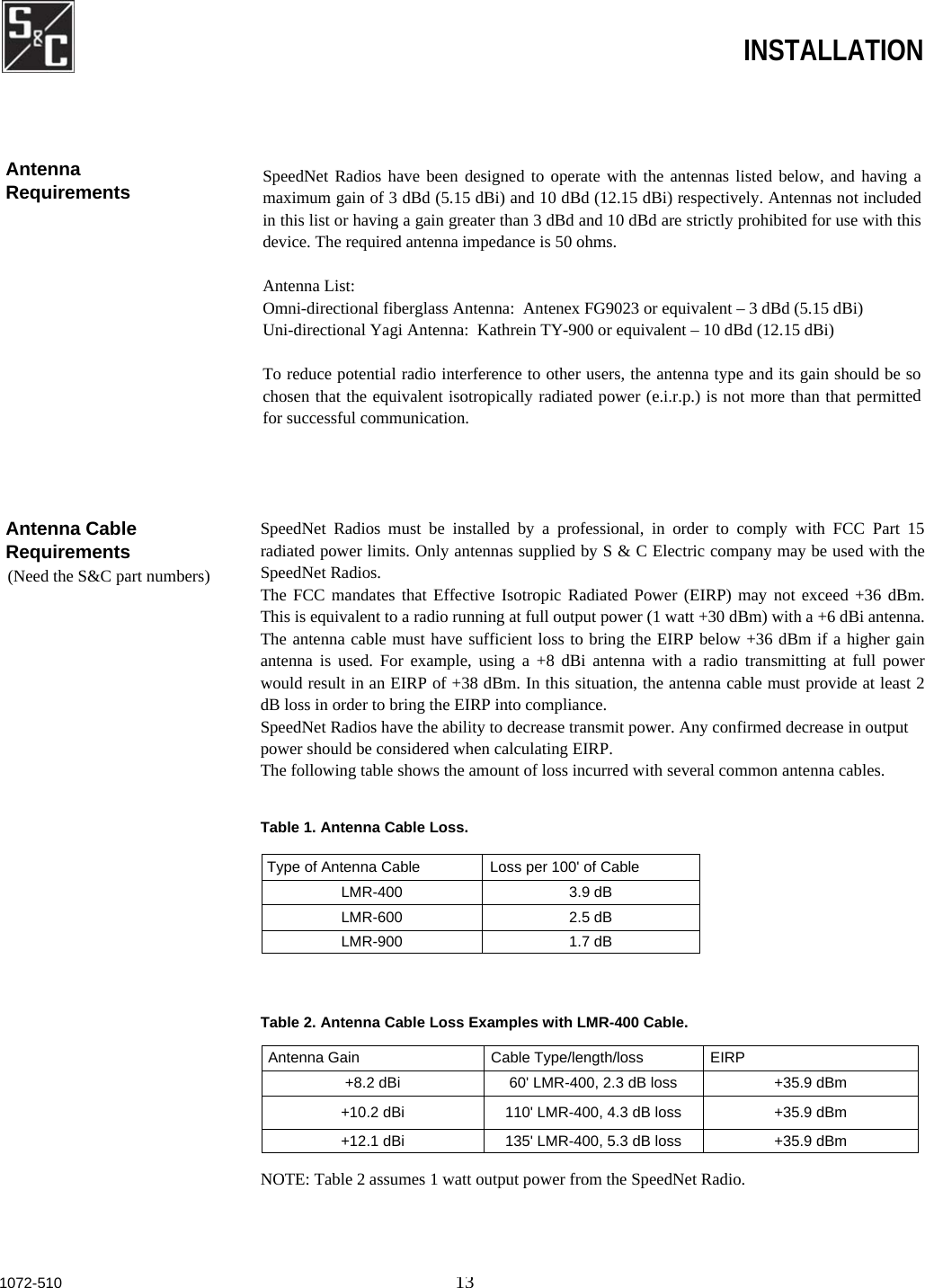
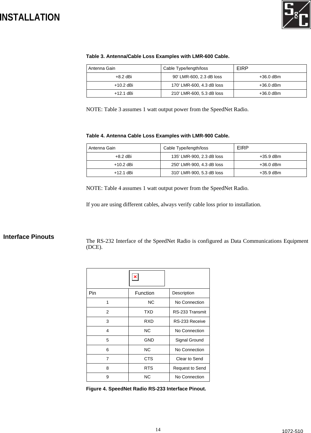
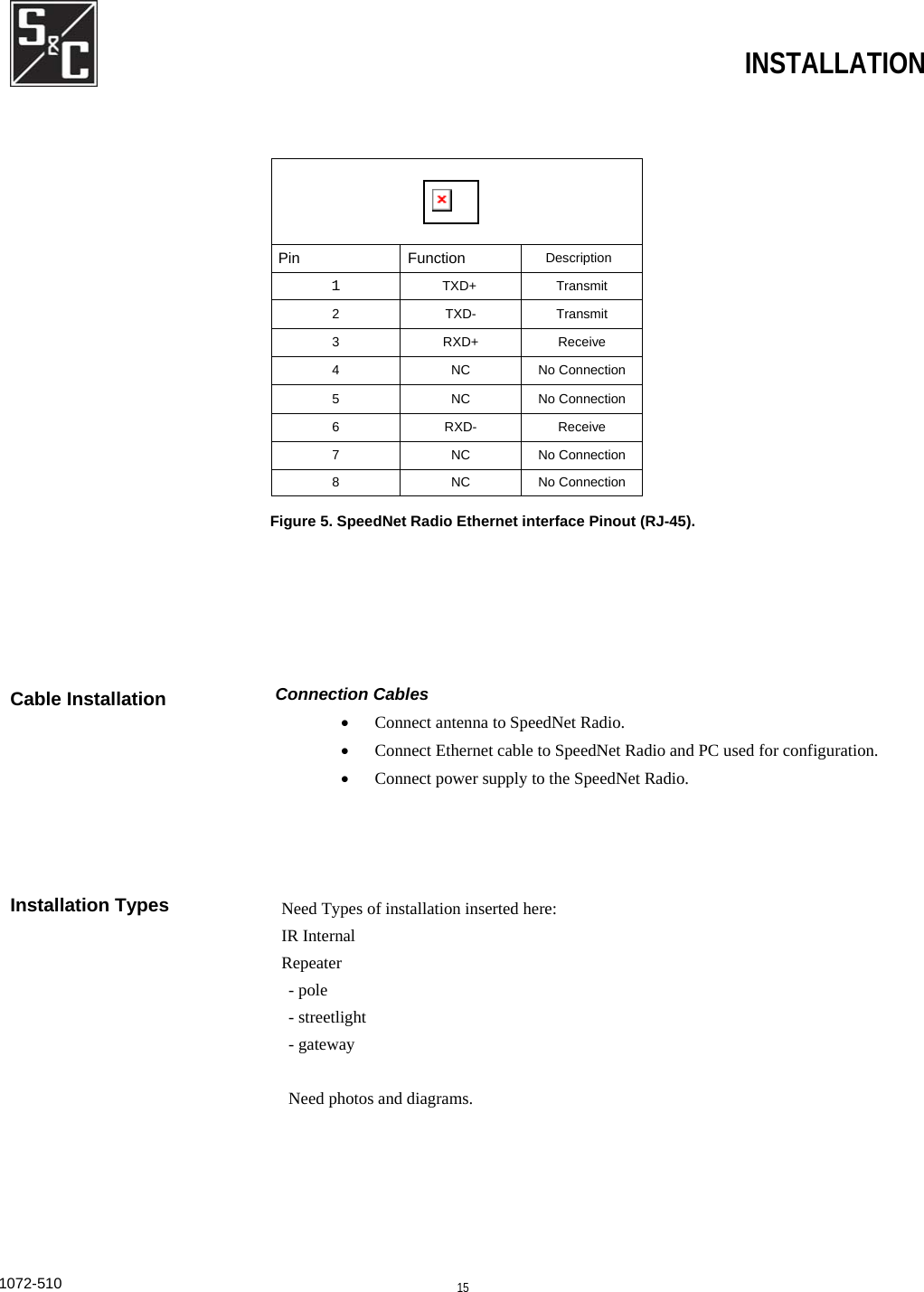
SPEEDNET User Manual
User Manual
Navigation menu
Upload a User Manual
Namespaces
Wiki Guide
HTML
PDF
Info
Views
User Manual
Discussion / Help
Navigation