S and C Electric SPEEDNET FHSS Radio User Manual 1072 510 4 9 08
S&C; Electric Company FHSS Radio 1072 510 4 9 08
User Manual

S&C SpeedNet® Radio
Installation Instructions
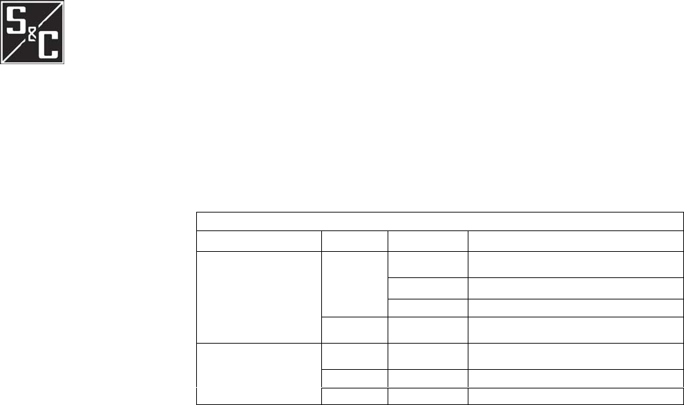
TABLE OF CONTENTS
Section Page
INTRODUCTION
Qualified Persons............................................................. .2
Read this Instruction Sheet.............................................. .2
Retain this Instruction Sheet............................................ .2
Latest Document Release. ............................................... .2
Warranty........................................................................... 2
SAFETY INFORMATION
Understanding Safety-Alert Messages............................. .3
Following Safety Instructions.......................................... .3
Replacement Instructions and Labels. ............................. .3
Section Page
INSTALLATION
Overview. .........................................................................4
Pre-Installation Checklist................................................. .4
IP Setup.............................................................................4
Network Example.............................................................8
Routing Options..............................................................10
Regulatory Information...................................................12
Antenna Requirements................................................... .13
Antenna Cable Requirements..........................................13
Interface Pinouts ............................................................ .14
Cable Installation........................................................... .15
Installation Types............................................................15
Excellence Throu
g
h Innovation
S&C ELECTRIC COMPANY Instruction Sheet 1072-510
April 9, 2008 ©2008
New Publication

INTRODUCTION
Qualified Persons
Read this Instruction
Sheet
Retain this
Instruction Sheet
Latest Document
Release
Warranty
WARNING
The equipment covered by this publication must be installed, operated, and maintained b
y
qualified persons who are knowledgeable in the installation, operation, and maintenance of local
area networking and routing functions along with the associated hazards. A qualified person is
one who is trained and competent in:
• Radio technicians must be qualified to install transmission power limited radio equipment,
per FCC Part 15.
• The skills and techniques necessary to distinguish exposed live parts from non-live parts o
f
electrical equipment.
• The skills and techniques necessary to determine the proper approach distances
corresponding to the voltages to which the qualified person will be exposed.
• The proper use of the special precautionary techniques, personal protective equipment,
insulating and shielding materials, and insulated tools for working on or near expose
d
energized parts of electrical equipment.
These instructions are intended only for such qualified persons. They are not intended to be
a
substitute for adequate training and experience in safety procedures for this type of equipment.
Thoroughly and carefully read this instruction sheet before programming, operating, o
r
maintaining your S&C SpeedNet Radios. Familiarize yourself with the safety information on page
3.
This instruction sheet is a permanent part of your S&C SpeedNet Radio. Designate a location
where you can easily retrieve and refer to this publication. This documentation is also available a
t
the S&C website: www.sandc.com.
The latest release of this instruction sheet is available online at www.sandc.com. Select:
Support/Product Support Documents. Documents are posted in PDF format.
The standard warranty contained in S&C's standard conditions of sale, as set forth in Price Shee
t
150, applies to the S&C SpeedNet Radio, except that the first paragraph of said warranty is
replaced by the following:
(1) General: Seller warrants to immediate purchaser or end user for a period of 10 years from the
date of shipment that the equipment delivered will be of the kind and quality specified in the
contract description and will be free of defects of workmanship and material. Should any failure to
conform to this warranty appear under proper and normal use within ten years after the date o
f
shipment the seller agrees, upon prompt notification thereof and confirmation that the equipmen
t
has been stored, installed, operated, inspected, and maintained in accordance wit
h
recommendations of the seller and standard industry practice, to correct the nonconformity eithe
r
b
y repairing any damaged or defective parts of the equipment or (at seller's option) by shipment o
f
necessary replacement parts. The seller's warranty does not apply to any equipment that has bee
n
disassembled, repaired, or altered by anyone other than the seller. This limited warranty is grante
d
only to the immediate purchaser or, if the equipment is purchased by a third party for installation
in third-
p
arty equipment, the end user of the equipment. The seller's duty to perform under any
warranty may be delayed, at the seller's sole option, until the seller has been paid in full for all
goods purchased by the immediate purchaser. No such delay shall extend the warranty period.
Replacement parts provided by seller or repairs performed by seller under the warranty fo
r
the original equipment will be covered by the above special warranty provision for its duration.
Replacement parts purchased separately will be covered by the above special warranty provision.
1072-510 2

SAFETY INFORMATION
Warranty of the SpeedNet Radio is contingent upon the installation, configuration, and use o
f
the SpeedNet Radio and software in accordance with S&C's applicable instruction sheets. This
warranty does not apply to major components not of S&C manufacture, such as batteries, an
d
other communication devices. However, S&C will assign to immediate purchaser or end user all
manufacturer's Warranties that apply to such major components.
Understanding
Safety-Alert
Messages
There are several types of safety-alert messages which may appear throughout this
instruction sheet as well as on labels attached to the SpeedNet Radio. Familiarize
yourself with these types of messages and the importance of the various signal words, as
ex
p
lained below.
DANGER
"DANGER" identifies the most serious and immediate hazards which will likely result i
n
serious personal injury or death if instructions, including recommended precautions, are not
followed.
WARNING
"WARNING" identifies hazards or unsafe practices which can result in serious personal
injury or death if instructions, including recommended precautions, are not followed.
CAUTION
"CAUTION" identifies hazards or unsafe practices which can result in minor personal injury
or product or property damage if instructions, including recommended precautions, are no
t
followed.
"NOTICE" identifies important procedures or requirements that can result in product o
r
p
roperty damage if instructions are not followed.
Following Safety
Instructions If you do not understand any portion of this instruction sheet and need assistance, contact you
r
nearest S&C Sales Office or S&C Authorized Distributor. Their tele
p
hone numbers are listed o
n
S&C's website www.sandc.com. Or call S&C Headquarters at (773) 338-1000; in Canada, call
S&C Electric Canada Ltd. at (416) 249-9171.
DANGER
Read this instruction sheet thoroughly and carefully before
installing or operating your S&C SpeedNet Radio.
Replacement
Instructions
and Labels
If you need additional copies of this instruction sheet, contact your nearest S&C Sales Office,
S&C Authorized Distributor, S&C Headquarters, or S&C Electric Canada Ltd.
It is important that any missing, damaged, or faded labels on the equipment be replace
d
immediately. Replacement labels are available by contacting your nearest S&C Sales Office, S&C
Authorized Distributor, S&C Headquarters, or S&C Electric Canada Ltd.
3
1072-510
NOTICE

INSTALLATION
Overview These instructions describe steps you should complete in the shop prior to field installation, an
d
field installation steps that are specific to the SpeedNet Radio.
Pre-Installation
Checklist Before you install the SpeedNet Radio, carry out the following steps. This is best done in the shop
before you leave for the installation site.
1. Choose a location.
The SpeedNet Radio should be securely mounted.
For remote antenna installations, S & C recommends lightning protection.
2. Plan your network.
SpeedNet Radio can be used in a wide variety of network configurations. Planning you
r
network in advance is recommended. You can develop a logical IP addressing scheme fo
r
your particular application. Depending on your type of network, several factors may
influence your planning:
• Point-to-point vs. mesh vs. Point-to-Multi Point
• Standalone Network Connection
Once the network topology is determined, the SpeedNet Radios can be configured
appropriately.
IP Setup AODV
SpeedNet Radios use a proprietary AODV (Ad-hoc On demand Distance Vector) routing system,
that works dynamically to maintain message routing. New routes are established with a route
request/route reply query cycle. When a source node needs to contact a destination that is no
t
stored in its route lookup table, it broadcasts a route request (RREQ) packet across the network.
Nodes receiving this packet update their information for the source node and create reverse
pointers to the source node in their route tables. If a receiving node is either the destination node o
r
has stored a route to the destination with a corresponding sequence number greater than or equal to
that contained in the RREQ, it will send a route reply (RREP) to the source node. Otherwise, i
t
rebroadcasts the RREQ. Nodes keep track of the RREQ’s source IP address and broadcast ID. I
f
they receive a RREQ that has already been processed, they discard the RREQ and do not forwar
d
the packet. As the RREP propagates back to the source, nodes create forward pointers to the
destination. Upon receiving the RREP, the source node will begin forwarding data to the
destination. If the source node later receives a RREP containing a greater sequence number or the
same sequence number with a smaller hop count, it may update its routing information for tha
t
destination and use the better route.
A route is maintained as long as it remains active, and is considered active when dat
a
p
eriodically travels that route. When the source stops sending data packets, the route will time out,
and eventually be deleted from the destination and intermediate node routing tables. If a lin
k
b
reakage occurs while the route is active, the node upstream of the break propagates a route erro
r
(RERR) message to the source node, informing it of the now unreachable destination(s). Afte
r
receiving an RERR, the source node can reinitiate route discovery, if the route is still required. The
received signal strength (RSSI) and number of hops required by the path are also recorded in the
lookup table, and these are considered when a node selects a route from its lookup table.
1072-510
4
CAUTION

INSTALLATION
The AODV protocol generates fewer transmissions, and conserves network capacity. Each
route request has a sequence number tracked by the nodes, so that they will not repeat a previous
route request. Route requests also have a time-to-live indicator, that restricts the number of times
they will be transmitted. AODV also creates no route discovery transmissions when a message is
traveling an existing route. Distance vector routing is simple, and doesn't require much memory o
r
calculation. Because standard AODV requires extra time to establish a connection, the SpeedNe
t
algorithm remembers its critical routes, such as the peer-to-peer IED routes within the power-gri
d
distribution infrastructure.
IP Basics
An Internet Protocol (IP) address is the unique identifier for a node (host connection) on an IP
network. The IP address is a 32 bit binary number, usually shown as 4 decimal values separated by
decimal points. Each value represents 8 bits in the range 0 to 255 (known as octets), and this is
called "dotted decimal" notation.
For example: 172.26.220.200 can be viewed in binary form:
172 .26 .220 .200
10 1 0 11 00.000 11 0 1 0.11 0 11100.11 00 1 000
Every IP address consists of two parts that identify the network and the node. The address
class and subnet mask determine which part belongs to the network address and which par
t
belongs to the node address.
There are five address classes. You determine the IP address class by examining the first 4
bits of the IP address.
• Class A addresses begin with Oxxx, or 1 to 126 decimal.
• Class B addresses begin with IOxx, or 128 to 191 decimal.
• Class C addresses begin with 110x, or 192 to 223 decimal.
• Class D addresses begin with 1110, or 224 to 239 decimal.
• Class E addresses begin with 1111, or 240 to 254 decimal.
Addresses beginning with 01111111, or 127 decimal, are reserved for loop back and internal
testing on a local machine. You can test this by pinging 127.0.0.1, which points to your local
machine. Class D addresses are reserved for multicasting, and Class E addresses are reserved fo
r
future use, and should not be used for a host address.
This is how the class determines, by default, which part of the IP address
belongs to the network (N) and which part belongs to the node (n).
• Class A - NNNNNNNN.nnnnnnnn.nnnnnnnn.nnnnnnnn
• Class B - NNNNNNNN.NNNNNNNN.nnnnnnnn.nnnnnnnn
• Class C - NNNNNNNN.NNNNNNNN.NNNNNNNN.nnnnnnnn
In the example, 172.26.220.200 is a Class B address so by default the Network part of the
address (known as the Network Address) is defined by the first two octets (172.26. x.x) and the
node part is defined by the last 2 octets (x.x.220.200).
To specify the network address in an IP address, the node section is entered as zeros. In our
example, 172.26.0.0 specifies the network address for 172.26.220.200. When the node section is
set to all "1"s, it specifies a broadcast that is sent to all nodes on the network, and is indicated:
172.26.255.255, which is the broadcast address for our example. Note that this is true for all
classes, regardless of the length of the node section.
51072-510

INSTALLATION
Private Subnets
There are three IP network addresses reserved for private networks. The addresses are 10.0.0.0,
Subnet Mask 255.0.0.0, 172.16.0.0, Subnet Mask 255.240.0.0, and 192.168.0.0, Subnet Mask
255.255.0.0. These addresses are also notated 10.0.0.0/8, 172.16.0.0/12, and
192.168.0.0/16;. They can be used by anyone setting up internal IP networks, such as a lab or home
LAN behind a NAT or proxy server or a router. It is always safe to use these because routers on the
Internet by default will never forward packets coming from these addresses.
Subnetting an IP Network can be done for a variety of reasons, including organization, use
of different physical media (such as Ethernet, FDDI, WAN, etc.), preservation of address space,
and security. The most common reason is to control network traffic. In an Ethernet network, all
nodes on a segment see all the packets transmitted by all the other nodes on that segment.
Performance can be adversely affected under heavy traffic loads, due to collisions and the
resulting retransmissions. A router is used to connect IP networks to minimize the amount of
traffic each segment must receive.
Subnet Masking
Applying a subnet mask to an IP address allows you to identify the network and node parts o
f
the address. The network bits are represented by the “1”s in the mask, and the node bits are
represented by the “0”s. Performing a bitwise logical AND operation between the IP address and
the subnet mask results in the Network Address or Number.
For example, using our test IP address and the default Class B subnet mask, we get:
10001100.00011010.11110000.11001000 172.26.240.200 Class B IP Address
11111111.11111111.00000000.00000000 255.255.000.000 Default Class B Subnet Mask
10001100.00011010.00000000.00000000 172.26.000.000 Network Address
Default subnet masks:
• Class A - 255.0.0.0 -11111111.00000000.00000000.00000000
• Class B - 255.255.0.0 -11111111.11111111.00000000.00000000
• Class C - 255.255.255.0 - 11111111.11111111.11111111.00000000
MAC Address
In networking, the Media Access Control (MAC) address is a unique identifier programmed into
each network device. This number acts like a name for a the device, and all SpeedNet Radios
have unique MAC addresses. Some devices have user configurable MAC addresses, but the
SpeedNet Radio MAC address is configured at the factory and cannot be changed. Most protocols
use MAC addresses that are globally unique, but not all protocols use MAC addresses, or require
that they be unique.
Unlike IP addresses, MAC addresses do not have node and Network sections, and a
receiving node cannot determine any network information from the MAC address. The length of a
MAC address is 6 bytes and an IP address is 4 bytes long, therefore the MAC address cannot be
represented using an IP address. So an IP address must be mapped to its corresponding MAC
address. Address Restoration Protocol (ARP) is used to locate a specific MAC address. ARP
broadcasts an ARP request packet, which contains the source MAC address, the source IP
address, and the destination IP address. Each node in the local network receives this packet. A
node that has the specified destination IP address, returns an ARP reply packet with its IP address
to the originating host. Eventually the path will extend to the destination IP address, and that
device will return the ARP packet that includes its MAC address.
1072-510 6
INSTALLATION
On broadcast networks, such as Ethernet, the MAC address allows each node to be uniquely
identified and allows frames to be marked for specific nodes. It thus forms the basis of most o
f
the layer 2 networking upon which higher OSI Layer protocols are built, to produce complex
functioning networks.
71072.510
OSI Model
Data Unit Layer Function
Data Application Network process to application.
IntelliRupter/IntelliTEAM
Presentation Data representation and encryption
Session Interhost communication
Host lED (Intelligent
Electronic Device)
Layers
Segments Transport End-to-end connections and reliability
(UDP/TCP)
Packets Network
Path determination and logical addressing
(IP)
Frames Data Link Physical addressing (MAC & LLC)
Media SpeedNet
Layers
Bits Physical Media. Wireless, Fiber Optics and Wire

INSTALLATION
Network Example Use of private IP addresses is strongly recommended when configuring a SpeedNet Radio
network. The following example of a SpeedNet Radio network uses several private IP subnets
from the 192.168.0.0 block of private addresses.
The SpeedNet Radio network, depicted in Figure 1, contains three Ethernet segments. The
first segment uses the 192.168.200.0 Class C subnet, encompassing a range of addresses fro
m
192.168.200.1 to 192.168.200.254. The second segment uses the 192.168.201.0 Class C subnet,
encompassing a range of addresses from 192.168.201.1 to 192.168.201.254. The third segmen
t
uses the 192.168.202.0 Class C subnet, encompassing a range of addresses from 192.168.202.1 to
192.168.202.254. All three segments share the 192.168.203.0 Class C subnet for their wireless
interfaces. It is over this common subnet that traffic is routed between Ethernet segments.
Figure 1. Multi-Network SpeedNet Radio Example, with Automatic Switch Controls (lED).
Once the individual data networks are established, it is recommended that you plan an IP
addressing scheme. In Figure 1 each SpeedNet Radio host ID is 1, while the IED's host ID is 2.
Following a numbering scheme such as this will make it easier to keep track of which IP
addresses are used for each device.
The SCADA network in this example uses the 192.168.203.0 subnet. This subnet is different
than the subnets used for the Ethernet segments. The wireless interface of the SpeedNet Radio
from Subnet 1 is assigned an address of 192.168.203.1. The wireless interface of the SpeedNet
Radio from Subnet 2 is assigned an address of 192.168.203.2. The wireless interface of the
SpeedNet Radio from Subnet 3 is assigned an address of 192.168.203.3.
You may find it helpful to draw a diagram as a planning aid when designing your SCADA
network. Such a diagram will not only help in planning the networks, it will be a reference guide.
1072.510 8
INSTALLATION
91072-510
1072-510
Figure 2. Example of a Network Using SpeedNet AODV.
Routing Options As a router, SpeedNet Radios provide a wireless connection between two or more separate
Ethernet subnets. Data is then routed between the Ethernet subnets. Route information can be
entered manually, or can be processed automatically by AODV, the SpeedNet Radio algorithm.
The type of network you are designing will help determine the best routing mode to use. I
f
the network consists of stationary SpeedNet Radios that are communicating either point-to-
p
oin
t
or point-to-multipoint, choose "Off”' for Ad Hoc Routing mode. This allows you to insert static
routes for each SpeedNet Radio and its connected network. If routes are not required to change
dynamically, "Off” is likely the best Ad Hoc Routing mode to choose. See Figure 3.
If the network consists of meshed SpeedNet Radios, choose "AODV," the Ad Hoc Routing
mode. This mode allows the SpeedNet Radios to automatically find their neighbors and update the
route tables to reflect this. AODV allows SpeedNet Radios to quickly and dynamically update the
route tables as the network topology changes. For environments where routes are required to
change dynamically, AODV is typically the best Ad Hoc Routing mode to choose.
Using Static Routes
Figure 3 is an example of a point-to-point SpeedNet Radio network. In this example, Subnet 1 has
b
een assigned the 192.168.1.0 Class C subnet, while Subnet 2 has been assigned the 192.168.2.0
Class C subnet. For the wireless network the 192.168.3.0 Class C subnet has been assigned.
In order to route traffic
b
etween subnets, several things must happen. First, it is
recommended that all hosts on a given subnet use the attached SpeedNet Radio as their defaul
t
gateway. As an alternative, manual routes can be entered in each host's routing table. Hosts fro
m
Subnet 1 will list 192.168.1.1 as their default gateway. It is also necessary to add static routes i
n
each SpeedNet Radio. The SpeedNet Radio from Subnet 1 must have a static route to Subnet 2,
using the SpeedNet Radio from Subnet 2 as the gateway. The route should be set up like this:
192.168.2.0 255.255.255.0 192.168.3.2
N
etwor
k
N
etmas
k
Gateway
10 1072-510
INSTALLATION
Figure 3. Wireless Network Using SpeedNet Radios with Static Routes.

INST
A
LLATION
It is recommended that all hosts from Subnet 2 use 192.168.2.1 as their default gateway. As an
alternative, manual routes can be entered in each host's routing table. The SpeedNet Radio from
Subnet 2 must have a static route to Subnet 1, using the SpeedNet Radio from Subnet 1 as the
gateway. This route should be set up like this:
192.168.1.0
N
etwor
k
255.255.255.0
N
etmas
k
192.168.3.1
Gateway
N
OTE: It is important to understand that there are actually three subnets in this example:
Subnet 1, Subnet 2 and the radio network.
1072-510 11

INSTALLATION
Regulatory
Information FCC Warning
This device complies with part 15 of the FCC rules. Operation is subject to the following two
conditions: 1) This device may not cause harmful interference and 2) this device must accept any
interference received, including interference that may cause undesired operation.
Any changes or modifications to this device without the express written consent of
S&C Electric Co, may void the user's authority to operate the device.
This device must be professionally installed. It is the responsibility of the installer to ensure
that proper antenna and cable combinations are used in order to remain within FCC Part 15 limits.
The SpeedNet is specifically designed to close the longest possible links. This goal is
accomplished in part by delivering the highest permissible RF output power to the antenna per the
FCC Part 15 Rules. In August 1996, the FCC adopted RF exposure guidelines that establishe
d
safety levels for various categories of wireless transceivers. Those limits are consistent with safety
standards previously published by the National Council on Radiation Protection (NCRP) Report
86, §17.4.1, §17.4.1.1, §17.4.2, and §17.4.3 as well as the American National Standards Institute
(ANSI) in §4.1 of "IEEE Standard for Safety Levels with Respect to Human Exposure to Radio
Frequency Electromagnetic Fields, 3kHz to 300GHz," ANSVIEEE C95.1-1992.
The SpeedNet complies with these FCC exposure guidelines when the following precautions
are obeyed:
• Only install the exact antennas recommended in this User Manual.
• The cable run for the selected antenna must exceed the minimum length quoted in this
User Manual.
• All persons must maintain a minimum separation of 12" (30.48cm) from any SpeedNe
t
antenna.
You should disconnect the AC/DC input power source from the SpeedNet whenever
repositioning the antenna. You are responsible for taking the necessary steps to ensure that these
guidelines are communicated to all persons that may come near the SpeedNet antennas.
Class A Digital Devices
N
OTE: This equipment has been tested and found to comply with the limits for a Class A digital
device, pursuant to Part 15 of the FCC Rules. These limits are designed to provide reasonable
protection against harmful interference when the equipment is operated in a commercial
environment. This equipment generates, uses, and can radiate radio frequency energy and, if not
installed and used in accordance with the instruction manual, may cause harmful interference to
radio communications.
12 1072-510
INSTALLATION
Antenna Cable
Requirements
(Need the S&C part numbers)
SpeedNet Radios must be installed by a professional, in order to comply with FCC Part 15
radiated power limits. Only antennas supplied by S & C Electric company may be used with the
SpeedNet Radios.
The FCC mandates that Effective Isotropic Radiated Power (EIRP) may not exceed +36 dBm.
This is equivalent to a radio running at full output power (1 watt +30 dBm) with a +6 dBi antenna.
The antenna cable must have sufficient loss to bring the EIRP below +36 dBm if a higher gai
n
antenna is used. For example, using a +8 dBi antenna with a radio transmitting at full powe
r
would result in an EIRP of +38 dBm. In this situation, the antenna cable must provide at least 2
dB loss in order to bring the EIRP into compliance.
SpeedNet Radios have the ability to decrease transmit power. Any confirmed decrease in output
power should be considered when calculating EIRP.
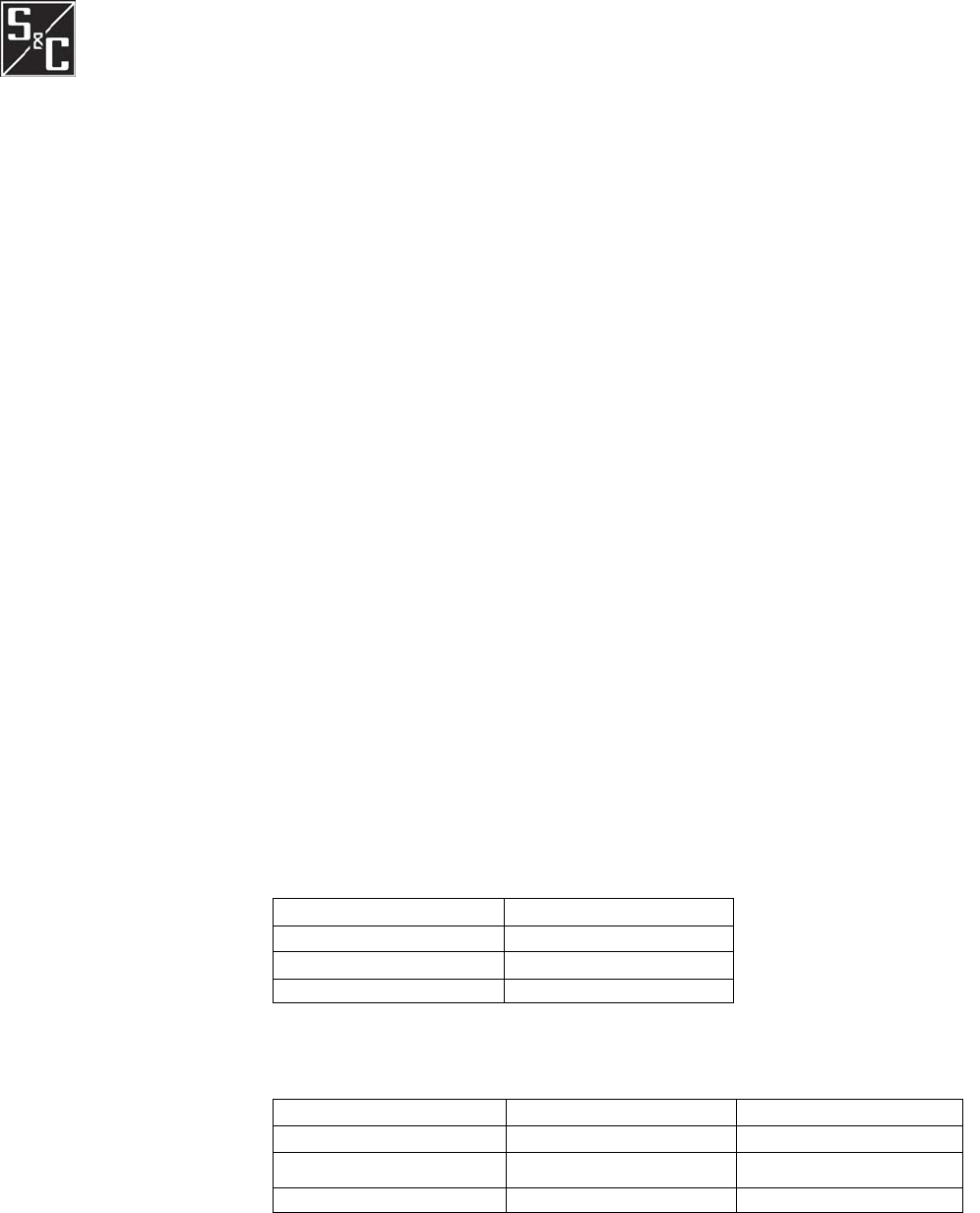
The following table shows the amount of loss incurred with several common antenna cables.
Table 1. Antenna Cable Loss.
Type of Antenna Cable Loss per 100' of Cable
LMR-400 3.9 dB
LMR-600 2.5 dB
LMR-900 1.7 dB
Table 2. Antenna Cable Loss Examples with LMR-400 Cable.
Antenna Gain Cable Type/length/loss EIRP
+8.2 dBi 60' LMR-400, 2.3 dB loss +35.9 dBm
+10.2 dBi 110' LMR-400, 4.3 dB loss +35.9 dBm
+12.1 dBi 135' LMR-400, 5.3 dB loss +35.9 dBm
N
OTE: Table 2 assumes 1 watt output power from the SpeedNet Radio.
1072-510
13
Antenna
Requirements SpeedNet Radios have been designed to operate with the antennas listed below, and having
a
maximum gain of 3 dBd (5.15 dBi) and 10 dBd (12.15 dBi) respectively. Antennas not include
d
in this list or having a gain greater than 3 dBd and 10 dBd are strictly prohibited for use with this
device. The required antenna impedance is 50 ohms.
Antenna List:
Omni-directional fiberglass Antenna: Antenex FG9023 or equivalent – 3 dBd (5.15 dBi)
Uni-directional Yagi Antenna: Kathrein TY-900 or equivalent – 10 dBd (12.15 dBi)
To reduce potential radio interference to other users, the antenna type and its gain should be so
chosen that the equivalent isotropically radiated power (e.i.r.p.) is not more than that permitte
d
for successful communication.
INSTALLATION
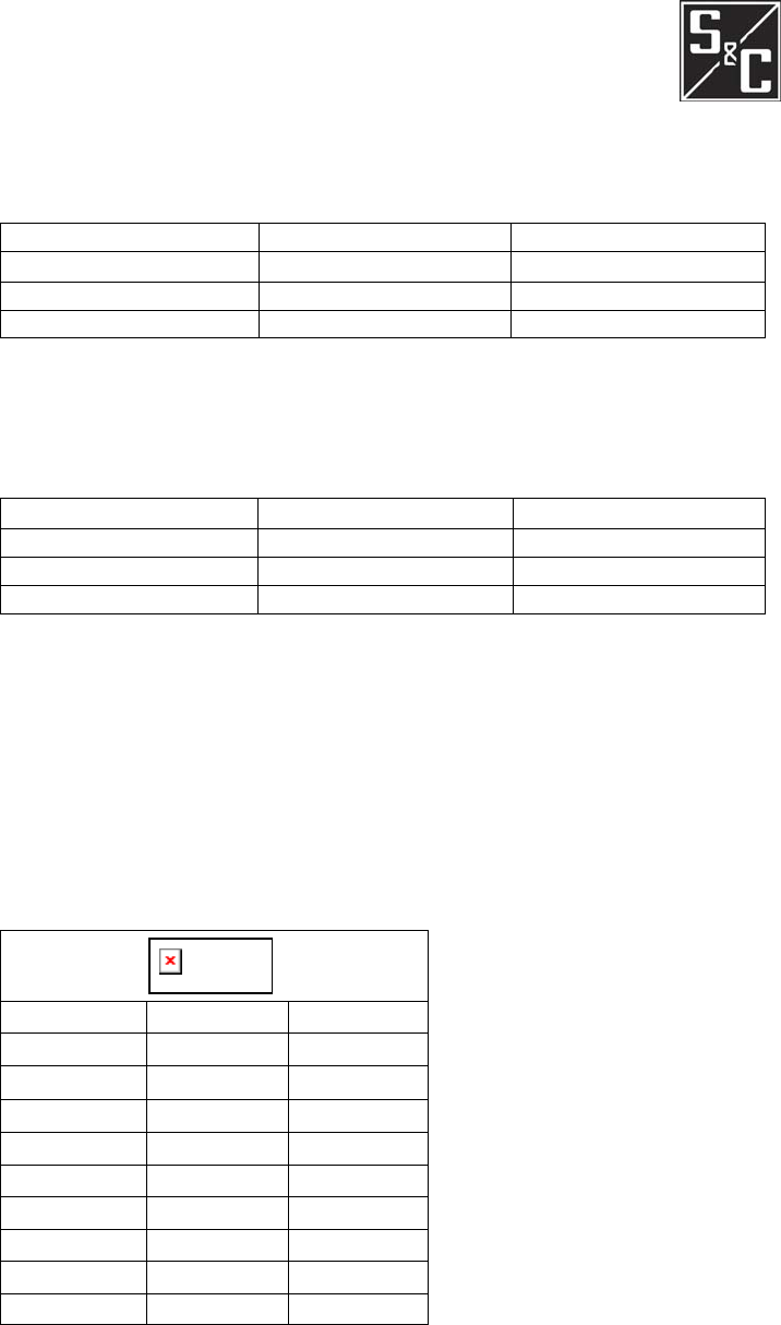
Interface Pinouts The RS-232 Interface of the SpeedNet Radio is configured as Data Communications Equipment
(
DCE
)
.
Pin Function
Description
1 NC No Connection
2 TXD RS-233 Transmit
3 RXD RS-233 Receive
4 NC No Connection
5 GND Signal Ground
6 NC No Connection
7 CTS Clear to Send
8 RTS Request to Send
9 NC No Connection
Figure 4. SpeedNet Radio RS-233 Interface Pinout.
14 1072-510
If you are using different cables, always verify cable loss prior to installation.
N
OTE: Table 4 assumes 1 watt output power from the SpeedNet Radio.
Antenna Gain Cable Type/length/loss EIRP
+8.2 dBi 135' LMR-900, 2.3 dB loss +35.9 dBm
+10.2 dBi 250' LMR-900, 4.3 dB loss +36.0 dBm
+12.1 dBi 310' LMR-900, 5.3 dB loss +35.9 dBm
Table 4. Antenna Cable Loss Examples with LMR-900 Cable.
N
OTE: Table 3 assumes 1 watt output power from the SpeedNet Radio.
Antenna Gain Cable Type/length/loss EIRP
+8.2 dBi 90' LMR-600, 2.3 dB loss +36.0 dBm
+10.2 dBi 170' LMR-600, 4.3 dB loss +36.0 dBm
+12.1 dBi 210' LMR-600, 5.3 dB loss +36.0 dBm
Table 3. Antenna/Cable Loss Examples with LMR-600 Cable.
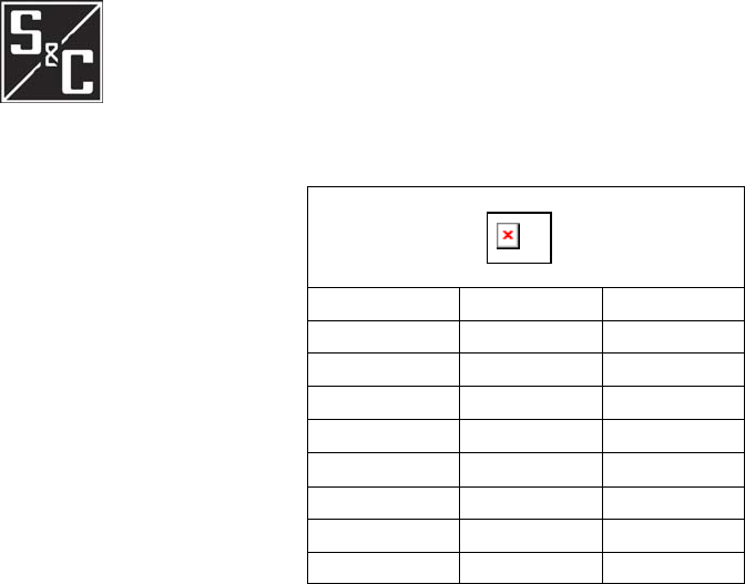
Figure 5. SpeedNet Radio Ethernet interface Pinout (RJ-45).
Pin Function
Description
1 TXD+ Transmit
2 TXD- Transmit
3 RXD+ Receive
4 NC No Connection
5 NC No Connection
6 RXD- Receive
7 NC No Connection
8 NC No Connection
N
eed Types of installation inserted here:
IR Internal
Repeater
- pole
- streetlight
- gateway
Need photos and diagrams.
INSTALLATION
Installation Types
Connection Cables
• Connect antenna to SpeedNet Radio.
• Connect Ethernet cable to SpeedNet Radio and PC used for configuration.
• Connect power supply to the SpeedNet Radio.
Cable Installation
1072-510 15