S and C Electric TSIICONTRL2 TripSaver Service Center Configurable Controller2 User Manual Module Integration Instruction
S&C; Electric Company TripSaver Service Center Configurable Controller2 Module Integration Instruction
Contents
- 1. Module Integration Instruction
- 2. Users manual
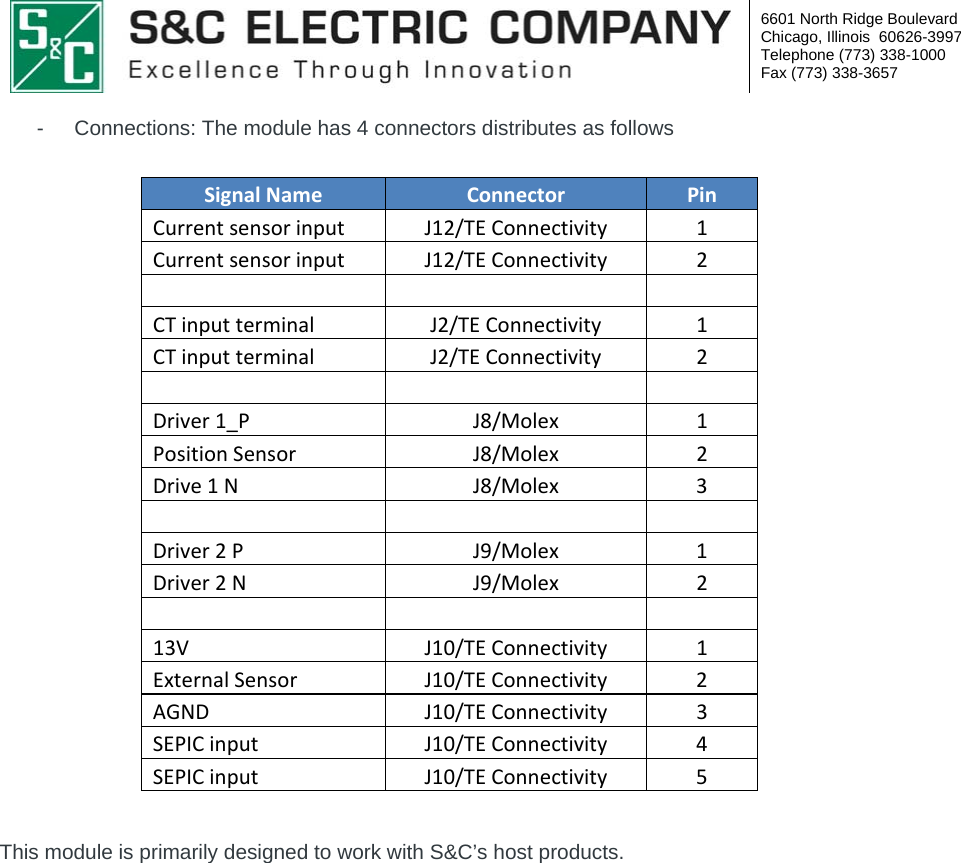
Module Integration Instruction