SABINE SW70-T BELTPACK TRANSMITTER User Manual USERS MANUAL A
Sabine, Inc. BELTPACK TRANSMITTER USERS MANUAL A
SABINE >
Contents
- 1. USERS MANUAL A
- 2. USERS MANUAL B
USERS MANUAL A

1Sabine 2.4 GHz Smart Spectrum® Wireless
E-SWM7000-OpGuide-031211.pmd - hto
Declaration of Conformity
EC - DECLARATION OF CONFORMITY
CE MARKING
We, the Manufacturer
SABINE, INC.
13301 NW US HIGHWAY 441
ALACHUA, FLORIDA USA
declare that the product
RECEIVER
SABINE MODEL SWM7000
Is in conformity with
Council Directive: 73/23/EEC and 89/336/EEC (EMC Directives)
Standards to which conformity is declared:
EN 60065: 2001
EN 55022: 1998 Class B
EN 50082-1: 1998
Manufacturer Signature: __________________________
Date: __________ Name: __________________________
Doran Oster, President28 April, 2003

2
Sabine 2.4 GHz Smart Spectrum® Wireless
Table of Contents
This operating guide written for USB enabled receivers using Sabine
SWM7000 Remote Control Software version 2.0 and above.
1. INTRODUCTION 3
1.1. Section Contents 3
2. PRODUCT VIEWS 4
2.1. Receivers 4
2.1.1. Front panel views 4
2.1.2. Back panel Views 4
2.2. Transmitters 5
2.2.1. Handheld 5
2.2.2. Beltpack 5
2.3. Components 5
3. QUICK SETUPS 6
3.1. Receiver & Transmitter Quick Setup 6
3.2. FBX Quick Setup 6
3.3. Tips for Good RF Performance 10
3.4. Common Sources of RF Interference 10
4. TRANSMITTER OPERATION 12
4.1. First step 12
4.2. Displays and Settings 12
4.2.1. LCD Display 12
4.2.2. Accessing Transmitter Controls 13
4.2.3. Adjusting Transmitter Settings 14
4.2.4. Transmitter Battery Management 15
5. RECEIVER OPERATION 18
5.1. LCD Display. 18
5.2. Parameter Control & LCD Display 20
5.2.1. One set of Controls for 1 or 2 Channels 20
5.2.2. Channel Select / Contrast Button. 20
5.2.3. Special LCD Display Messages. 21
5.3. RF Channel Select 21
5.4. Output Level 21
5.5. Receiver Antenna Placement 22
5.5.1. Multi-path Interference 22
5.5.2. Receiver & Antenna Placement Tips 22
6. MIC SUPERMODELING™ 24
6.1. Introduction 24
6.2. Emulation Choices 24
6.3. Mic Modeling Front Panel Control 24
6.4. Future Microphone Modeling Choices 25
6.4.1. Mic Model Upgrade Instructions 25
7. FBX FEEDBACK EXTERMINATOR® 26
7.1. FBX Introduction 26
7.1.1. FBX Fixed Filters 26
7.1.2. FBX Dynamic Filters 26
7.1.3. Balancing Fixed & Dynamic Filters 26
7.1.4. FBX Filter Width 26
7.2. FBX Set Up 26
7.2. FBX Bypass Button 27
8. COMPRESSOR/LIMITER OPERATION 28
8.1. Basics of Compression 28
8.2. Using the Compressor 28
8.3. Suggested Compression Settings 29
8.3.1. Vocal Settings 29
8.3.2. Guitar Settings 29
8.3.3. Bass Guitar Settings 29
8.5. Release & Knee Settings 30
9. DE-ESSER 31
9.1. De-mystifying De-essers 31
9.2. The Sabine De-esser 31
9.3. Using the De-esser 31
10. PROGRAM SAVE & RECALL 32
10.1. Saving a Preset 32
10.2. Loading a Preset 32
10.3. Naming a Preset 32
10.4. Power Off Memory 32
11. MULTIPLE SYSTEMS OPERATION 33
11.1. Overview 33
11.1.1. Multiple System Interference 33
11.1.2. Setup Complexity 33
11.2. Antenna Distribution Amplifier 34
11.3. Antenna Distribution Amplifier Connection 35
12. EXTENSION ANTENNAS 36
12.1. Overview 36
12.2. Antenna Cabling & Cable Loss 36
13. REMOTE CONTROL OPERATION 38
13.1. Overview 38
13.1.1. Single vs. Multiple Receiver Control 38
13.1.2 Features & Controls Added Software 38
13.1.3. Software Multiple Unit Control 40
13.2. Software Installation 40
13.2.1. Requirements & Recommendations 40
13.2.2. Connections 40
13.2.3. Installing the Software 41
13.3. Launching the software 41
13.3.1. Off-Line Edit/Demo 41
13.3.2. Connecting Receivers. 41
13.4. Remote Control Operation 42
13.4.1. Two Views, Two Sets of Controls 42
13.4.2. Menus, Icons & Hot Keys 42
14. TIPS & TROUBLESHOOTING 46
14.1. Tips for Maximum Performance 46
14.2. Troubleshooting 46
14.3. Common Sources of RF Interference 47
14.3.1 RF Sources 47
15. FBX THEORY & PRACTICE 49
15.1. Introduction to FBX® 49
15.2. The Advantages of FBX Filters 49
15.3. Parametric Filters and FBX 50
15.3.1. The FBX & True Mobility® Advantage 51
14.3.2. FBX Fixed & Dynamic Filters 51
14.3.3. FBX Filter Width 52
14.3.4. Who Benefits from FBX? 52
15. APPENDICES 53
Appendix A: Beltpack Connector Wiring Diagrams 53
Appendix B: Antenna System Diagrams 53
Appendix C: Specifications 54
Appendix D: Dip Switch Settings 55
Appendix E: Frequency Chart 55
Appendix F: Battery Endurance Tests (Typical) 56
Appendix G: Changing Audix Mic Capsules (SW70-H) 56
16. CAUTIONS & WARRANTY 57
INDEX 59

3Sabine 2.4 GHz Smart Spectrum® Wireless
E-SWM7000-OpGuide-031211.pmd - hto
1. INTRODUCTION
Congratulations on purchasing a Sabine 2.4 GHz Smart Spectrum True Mobility™ Wireless System. True Mobility™
Wireless Systems give you all the built-in processing you need on every microphone, and offer unique and powerful
features unavailable with any other wireless microphone
1.1. Section Contents
Section 2 Product Views — illustrates system components (front & back panel views, transmitters, accessory lists
and part numbers).
Section 3 Quick Setup — gives the Quick Setup procedures for Receiver & Transmitter Operation and using the FBX
Feedback Exterminator®. Note that there is also a quick-start label on top of your True Mobility receiver for
the Sabine FBX Feedback Exterminator®, Compressor/Limiter and De-Esser functions.
Section 4 Transmitter Operation — details transmitter setup and operation.
Section 5 Receiver Operation — details receiver installation and setup.
Section 6 Mic SuperModeling™ — explains the use of the Sabine Mic SuperModeling™ and lists the microphones
modeled.
Section 7 FBX Feedback Exterminator® — explains how to set up your FBX filters.
Section 8 Compressor/Limiter — explains the use of the Compressor.
Section 9 De-Esser — details operation of the adaptive De-Esser.
Section 10 Program Save & Recall — explains how to save and recall individual program settings.
Section 11 Multiple Systems — how multiple systems interface, computer control of multiple systems, suggestions
for maximizing the number of collocated systems.
Section 12 Extension Antennas — how to get maximum performance using a Sabine Extension Antennas (Antenna
Distribution Amplifier also available for multi-receiver installations).
Section 13 Sabine Remote Control Software — how to control up to 70 channels from one PC.
Section 14 Tips & Troubleshooting — gives tips on how to get the best performance from your Sabine Wireless, and
describes some possible operating problems and their solutions.
Section 15 Appendices — wiring diagrams, frequency charts, specifications, typical system diagrams and dip switch
settings for Sabine 2.4 GHz Wireless systems.
Section 16 Cautions & Warranties — states caution and warranty information for your True Mobility™ Wireless sys-
tem.
Index
Introduction
4
Sabine 2.4 GHz Smart Spectrum® Wireless
Product Views
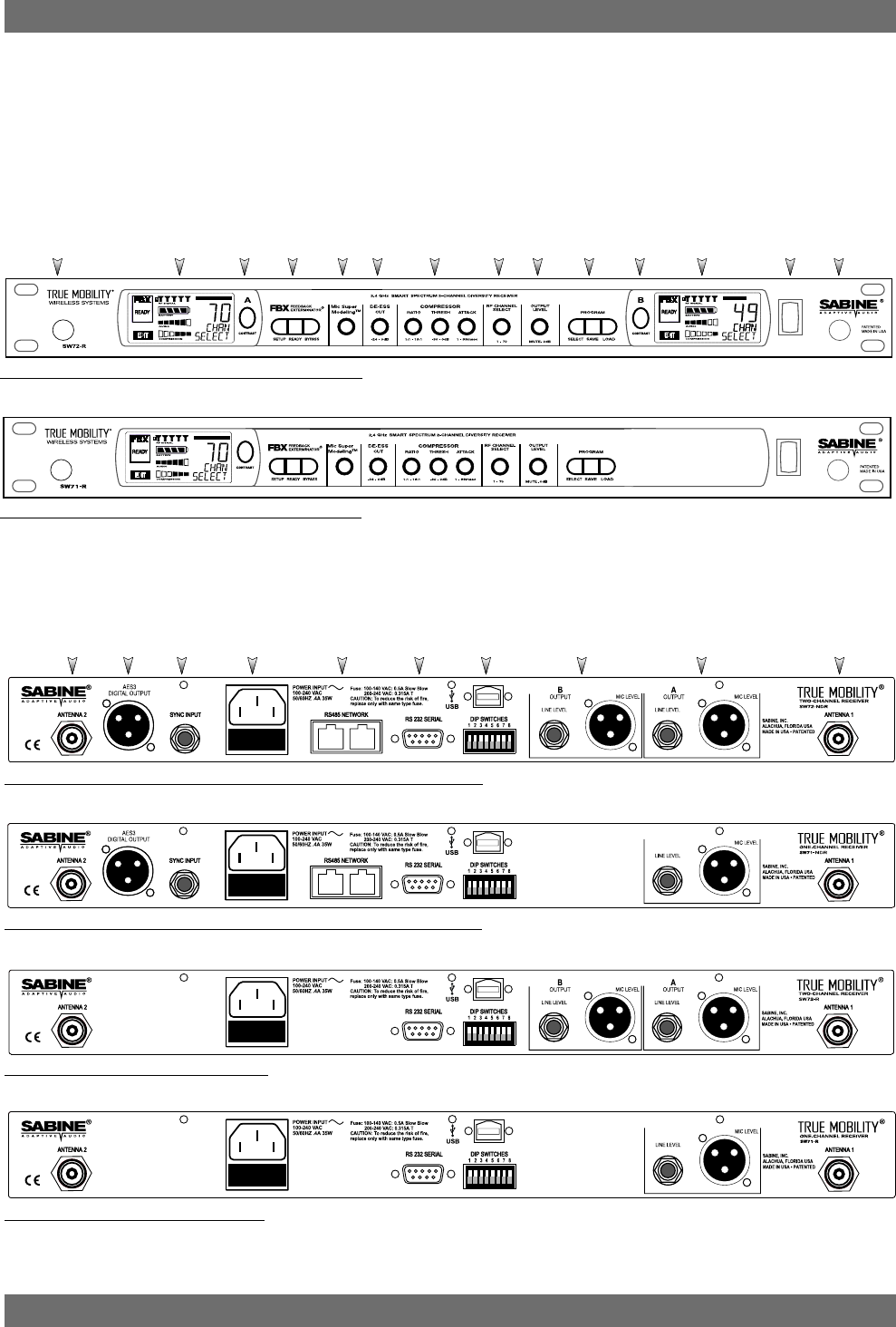
Ch. A
Channel
Select,
Contrast
Ch. B
Channel
Select,
Contrast
Fig. 2b - SW71-NDR & SW71-R One-channel Receivers
Fig. 2a - SW72-NDR & SW72-R Two-channel Receivers
Antenna 1
Front Mount Ch. A
Display Antenna 2
Front Mount
PowerCh. B
Display
ProgramOutput
Level
RF Ch.
Select
Compressor
Limiter
De-
esser
Mic
Model
FBX
Fig. 2f - SW71-R One-channel Receiver
Fig. 2e - SW72-R Two-channel Receiver
Fig. 2d - SW71-NDR One-channel Receiver w/Network & Digital Interface
Fig. 2c - SW72-NDR Two-channel Receiver w/Network & Digital Interface
Antenna 2 AES3
Digital Output Sync
Input AC Power
& Fuses RS485
Network RS232
Serial USB Port,
Dip Switches Mic/Line Balanced
Output B Mic/Line Balanced
Output A Antenna 1
2. PRODUCT VIEWS
2.1. Receivers
2.1.1. Front panel views
2.1.2. Back panel Views
5Sabine 2.4 GHz Smart Spectrum® Wireless
E-SWM7000-OpGuide-031211.pmd - hto
13
Product Views
Product Views
Fig. 2h - SWC70CL - SW70-HD3 & SW70-HD5 Mic Clip with Built-in Charger
Fig. 2i - SW70-T Beltpack Transmitter
2.3. Components
Receivers
SW72-NDR: 2-Ch. Receiver w/Network & Digital Interface
SW71-NDR: 1-Ch. Receiver w/Network & Digital Interface
SW72-R: 2-Ch. Receiver
SW71-R: 1-Ch. Receiver
Microphones
SWT24L-TA4: Cardioid Lavalier Mic
SWT36L-TA4: Omni Lavalier Mic
SWT56W-TA4: Headworn Mic
SWT70BW-TA4: Voice Technologies Omni Headworn Mic (Black)
SWT70LW-TA4: Voice Technologies Omni Headworn Mic (Tan)
SWTVT50-TA4: Voice Technologies Miniature Omni Lavalier
SWT70G-TA4: Instrument Input w/cable
Transmitters
SW70-T: Beltpack Transmitter
SW70-HD3: Handheld Mic w/Dynamic Element (Audix OM3)
SW70-HD5: Handheld Mic w/Dynamic Element (Audix OM5)
SW70-HC: Handheld Mic w/Condenser Element
Antennas
SWA700: TNC Front to Rear Converter Kit (Set of 2)
SWA6SS: 2.4 GHz Antenna Distribution Amp for 6 systems
SWASS-EXT: 2.4 GHz Extension Antenna Kit (Set of 2)
SWAANT-2.4: 2.4 GHz Antennas (2)
SWATNC-N: RF Adaptor cable, Set of 4, TNC to NB
SWATNC-MCA: TNC Male Crimp Connector 2.4 GHz
Batteries
SWBC1: Rechargeable NiMH C for SW70-H
SWBAA2: Rechargeable NiMH AA set for SW70-T
Mic & Transmitter Accessories
SWCRJ45: RS485 Serial Connection Cable for ND Receivers
SWCCL: SW70-H Mic Holder w/Built-in Charger
SWCCL-2: Stage clip for SW70-H
SWCPOWR-EXT: Charger extension cable (3 meters)
SWCPOWR: Plug-in charger for SW70 Series Transmitters
SWC4P-TA4: Standard Mini-XLR Connector
Wind Screens available for all mics
ALKALINE BATTERY CAUTION Alkaline batteries must be one of following types: NEDA: 14A ANSI: 14A IEC: LR14
!!
Antenna
Switch TA4
Mini-XLR
Connector
Top view
Belt clip
SWC-POWR
plug-in
charger jack
SELECT
ON
ON
ON
OFF
MUTE
ON
2.4 GHZ SMART SPECTRUM
3
12
Battery
Battery
SWC-POWR
plug-in charger jack
Shown with cable
attached. Requires
assembly.
Switch
Antenna Battery
LCD
SELECT
ON ON ON
OFF MUTE ON
2.4 GHZ SMART SPECTRUM
Transmitter Controls
1Select Button
2Up Button
3Down Button
2.2. Transmitters
2.2.1. Handheld
2
— DO NOT USE RECHARGEABLE ALKALINE BATTERIES —
2.2.2. Beltpack
6
Sabine 2.4 GHz Smart Spectrum® Wireless
3. QUICK SETUPS
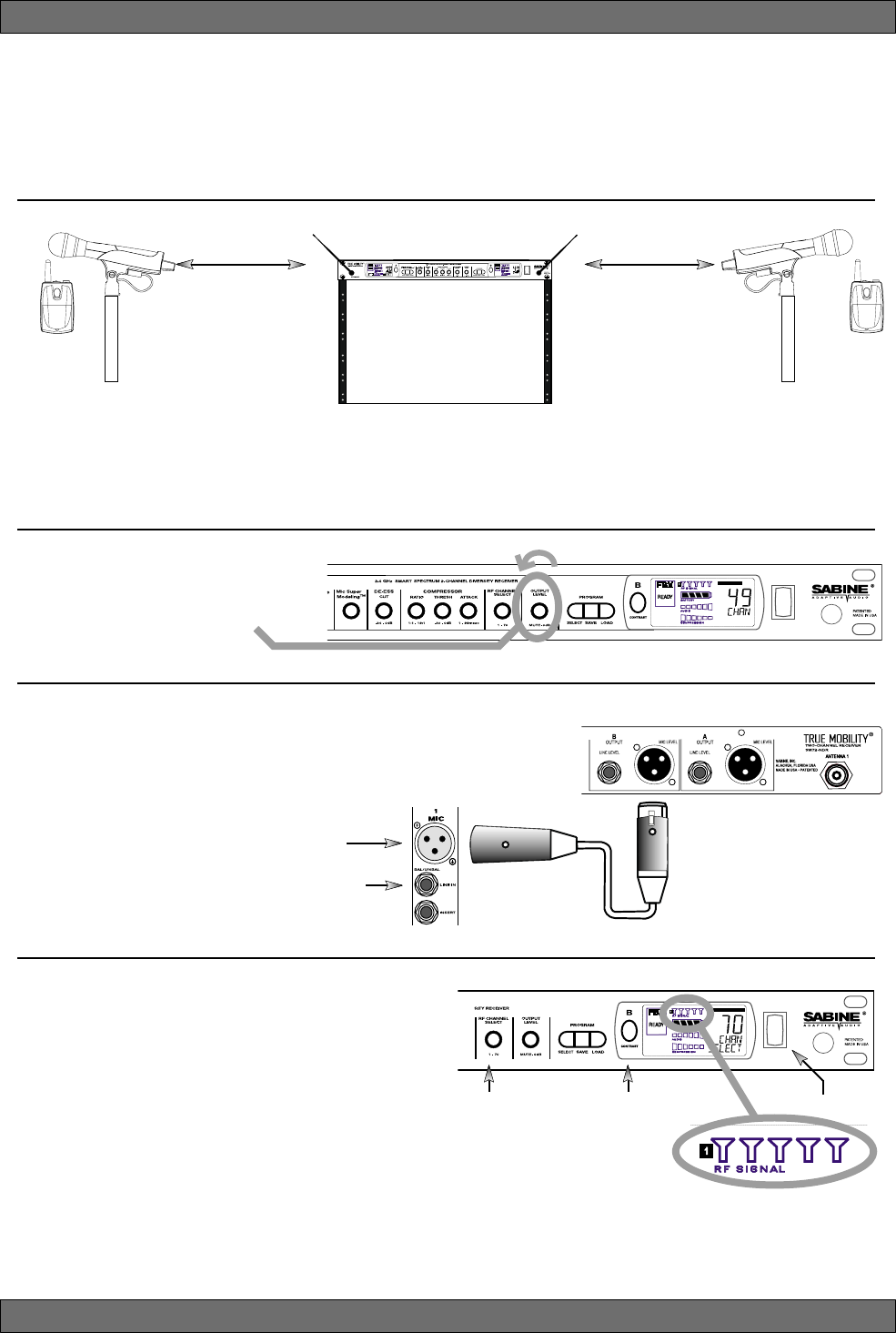
3.1. Receiver & Transmitter Quick Setup
Please read Section Four Transmitter Operation and Section Five Receiver Operation for a complete understanding of how to set up
your Sabine 2.4 GHz Smart Spectrum True Mobility
TM
System.
3.2. FBX Quick Setup
Quick Setups
Turn the OUTPUT LEVEL of the 2.4
GHz receiver and mixer gain to the
minimum settings.
2
Connect the output (¼-inch or XLR jack) of your 2.4 GHz True
MobilityTM receiver to the mic or line input of your mixer or am-
plifier (the receiver output gain can be adjusted to match the
mixer input).
3
Mixer Balanced Input
(XLR)
Mixer Unbalanced Input
(TRS)
1. Turn on the receiver.
2. Tap the Channel Select/Contrast button to edit
a receiver channel. (Not necessary on 1-chan-
nel SW71-R & SW71-NDR receivers).
3. Turn the RF Channel Selector knob to the de-
sired channel.
NOTE: Dual channel receivers will not allow you to select
the same RF channel for both channels.
4
Power SwitchRF Channel
Selector Channel Select/
Contrast button
(selects receiver
channel to edit)
Transmitter range is 100
meters line-of-sight
Be sure that all transmitters are off.
Position receiver so that the antennas are within visual range of the
intended transmitter locations. Transmitter range is about 100 meters, but structural objects in the transmission
path can reduce that range. For best results, maintain a line-of-sight path between receiver antennas and trans-
mitters (see Section 12). Use the TNC Rear-to-Front Kit (SWA700) included with the receiver to move antennas
to front if necessary. See Appendix B for more information on multiple-system connection.
Use Sabine’s SWASS-EXT
Extension Antenna Kit
when line-of-sight path is
not possible
1
NOTE: Front panel RF Signal display will only register Sabine transmitters. It will not show RF interference. Use the RF
Scan function in the software to scan for potential RF interference.
7Sabine 2.4 GHz Smart Spectrum® Wireless
E-SWM7000-OpGuide-031211.pmd - hto
6
Gain Adjustment Settings
1. Transmitter (PAD Adjustment).
Adjust the Transmitter PAD setting if
last segment of the Transmitter or Receiver Audio Level Meter lights up
often, or remains on when mic or beltpack is used.
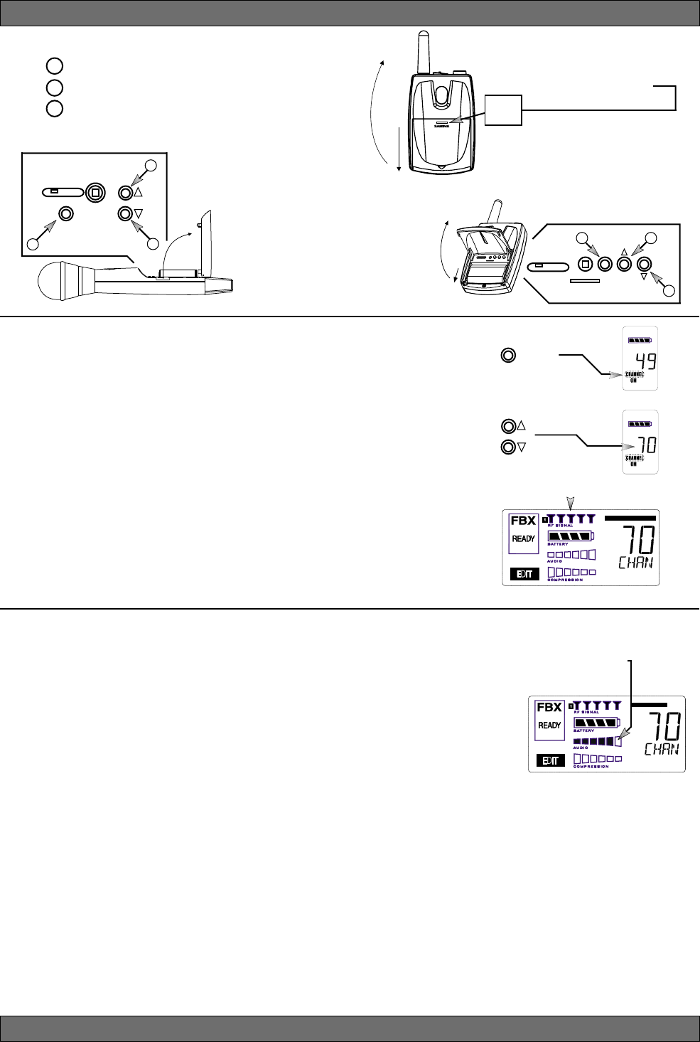
1. Use the Transmitter Select button to scroll through functions
until PAD flashes in the Transmitter LCD.
2. Use the Up or Down buttons to select the desired setting. Se-
lection is stored after 3 seconds of inactivity.
3. Check to see if Audio Level Meter stays out of Clipping Zone
1. Turn on the transmitter.
2. Use the SELECT button until CHANNEL appears in the LED. NOTE:
the transmitter is muted during editing.
3. Use the UP or DOWN button until the desired channel appears above
CHANNEL.
4. Check that the receiver’s RF SIGNAL display now indicates a strong
signal (at least 3 bars).
5
Quick Setups
To Close: Swing door down, flush with
transmitter body. Slide door up toward
LCD. Push in and up firmly on Battery
Door Handle with thumb until door lip
catches.
To Open: Press down firmly on Bat-
tery Door Handle and slide away from
LCD, then swing up and back.
2. Receiver. Adjust the receiver Output Level to supply a strong input level to the mixer, amplifier or active
loudspeaker. If your receiver output is connected to a microphone level input on the mixer, keep the receiver output
gain lower than when connecting to a line level mixer input. NOTE: -10 is a good place to start.
3. Mixer. Adjust the output gain of the mixer so that the mixer output meters approach clipping when all the inputs
to the mixer are active, and the audio program reaches its peak level.
4. Amplifier/active loudspeaker/crossover. Finally, adjust the amplifier gain control (and/or crossover gain, if
one is used) to provide the desired level of sound pressure in the auditorium or listening area.
Adjust PAD setting so that
Receiver Audio Level Meter
stays out of the clipping
zone (last segment)
SELECT
1
SELECT
ON ON ON
OFF MUTE ON
2.4 GHZ SMART SPECTRUM
2
3
SELECT
ON
ON
ON
OFF
MUTE
ON
2.4 GHZ SMART SPECTRUM
3
12
To Close: Swing door
down until it latches.
To Open: Swing door up
from indented area on body.
See Section 4.2.3 Adjusting Transmitter Settings for more information.
Beltpack Opening/Closing Instructions
BATTERY
DOOR
HANDLE
Transmitter Controls
1 Select Button
2 Up Button
3 Down Button
8
Sabine 2.4 GHz Smart Spectrum® Wireless
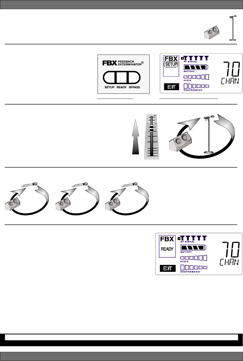
Fig. 3d - FBX: SETUP Fig. 3e - SETUP indicator flashing
Quick Setups
Place microphone and speakers in primary position.
Press and hold the SETUP button (Fig. 3d) on the receiver until the
1
2
LCD SETUP indicator (Fig. 3e)
flashes 4 times and SETUP stays lit
— then release it.
NOTE: DO NOT TALK INTO YOUR
SYSTEM while in Setup Mode.
Slowly raise the gain on the mixer or
amp until FBX eliminates the first few
feedback tones. With each new feed-
back frequency, you will hear a short, quiet burst of
feedback that will disappear immediately as a filter is
set.
Pause raising the gain, and move the microphone to
another area where it will be used. Resume slowly
raising the mixer gain, until FBX eliminates a few more
feedback tones.
Repeat until the SETUP indicator automatically turns
off and the READY indicator comes on.
NOTE: You may quit SETUP mode at any time prior to its automatic exit by simply pressing the READY button.
Location #1
Location #2 Location #3
This will enable ready-to-operate status, but with fewer fixed FBX
filters in place. In the default factory setting, dynamic FBX filters will
still be held in reserve to catch and eliminate new feedback, regard-
less of how or when SETUP mode is exited. (See Section 14.3.2 for
details on the differences between fixed and dynamic FBX filters and
Section 13.4.2.1 for instructions on changing the balance of fixed
versus dynamic FBX filters using the Remote Control Software or
Appendix D for using the Dip Switches on the back of the receiver).
3.2.2. FBX Bypass
The BYPASS button (Fig. 3d) bypasses only the FBX filters, and not the additional signal processing (de-essing,
compression and Mic SuperModelingTM) available on the True MobilityTM Wireless Receiver. This is a useful button
that allows comparison of the sound quality when FBX filters are in place, to the sound with no filters (the quality
should be very similar). Before pressing BYPASS, take care to reduce your overall system gain so that you do
not release suppressed feedback!
5
4
3
NOTE: When choosing microphone setup
locations, try to anticipate likely areas
where the microphone will be positioned
or moved to, or areas that may be espe-
cially prone to feedback problems (e.g.,
under an overhead speaker).
FBX BYPASS CAUTION
Bypassing FBX filters may allow suppressed feedback to be released!
Location #4 (if necessary)
Mixer Channel
9Sabine 2.4 GHz Smart Spectrum® Wireless
E-SWM7000-OpGuide-031211.pmd - hto
Quick Setups
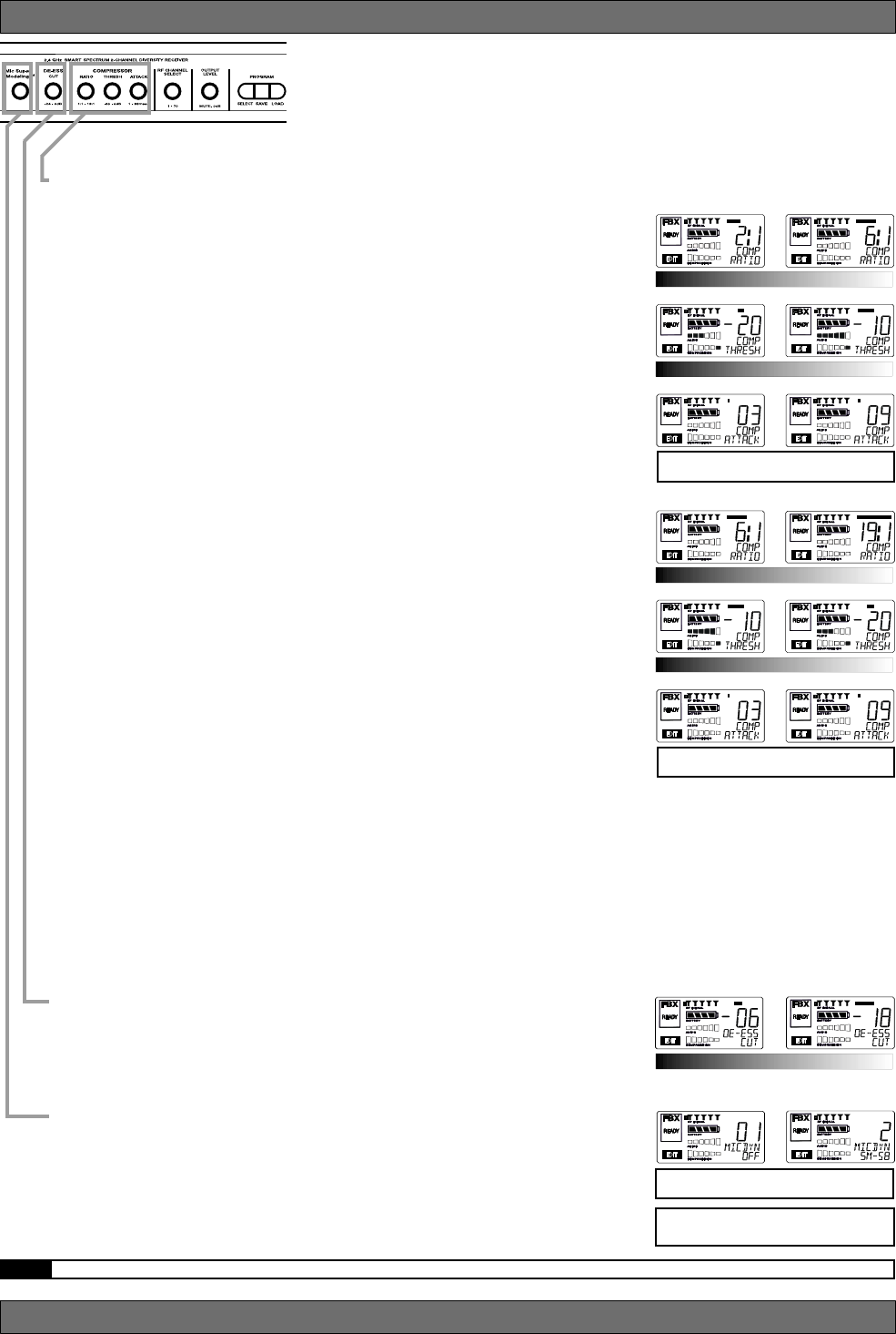
Vocal Settings
RATIO A soft voice could be set to 2:1, whereas a loud voice might
require a ratio setting of 6:1.
THRESH The higher the threshold setting, the more signal is required to
initiate compression. Ideally this should be set to reign in peak
levels, and allow signals of lower gain to pass uncompressed.
Threshold settings will depend on the nature and variety of the
signal source.
ATTACK Short attack times usually work well for voice. However, too
strong a compression ratio, too low a threshold, and too fast an
attack may attenuate speech consonants, which provide im-
portant intelligibility cues to the audience, thus compromising
clarity.
Guitar Settings
RATIO A high compression ratio (with gain makeup) will add sustain
to held notes and chords.
THRESH Moving the threshold will change the audible thick/thinness of
the guitar tone, but generally you want to compress all the notes
played.
ATTACK Be wary of too quick an attack, which may reduce the percus-
sive attack of the guitar notes.
In general, be wary of too much gain makeup, and too high a compres-
sion ratio, which may make a noisy guitar amplifier more objectionable.
Ratio settings might range from 6 to 19:1, threshold variable, slower
attack, soft knee, output gain boosted slightly to significantly depending
on amount of compression.
Bass Guitar Settings
RATIO Set to 4:1
THRESH Set to compress peaks only.
ATTACK Quick attack, medium release, hard knee; (try various release
settings, depending on the speed of notes played).
GAIN Output boosted slightly.
MIC SUPERMODELINGTM
DE-ESSER
RATIO
THRESH
ATTACK
RATIO
THRESH
ATTACK
NOTE: Use these settings as a place from which to start, then adjust to your own satisfaction.
Vocals
Short attack is better for vocals. Be careful not to
over attenuate speech consonants.
Soft voice Loud voice
Soft voice Loud voice
Guitar
Less Sustain More Sustain
Thinner sound Thicker sound
Be wary of too quick an attack, which may reduce the
percussive attack of the guitar notes.
NOTE: Mic SuperModelingTM is not avail-
able using beltpack transmitters.
COMPRESSOR/LIMITER
MIC SUPERMODELING
Scroll through available microphone settings. See
website for additional downloadable microphones.
Less reduction More reduction
DE-ESSER

10
Sabine 2.4 GHz Smart Spectrum® Wireless
Quick Setups
3.3. Tips for Good RF Performance
• Avoid potential sources of RF interference by performing a scan using
Sabine’s Remote Control Software., which will reveal the ambient RF level
in your area on each channel of your system. Please refer to Section 13.4.2.5.
for information on the RF Scan function, which will automatically determine
the best RF channels to use.
• If you cannot perform a scan then proceed to use your system, beginning
with Channel 1. If you hear any RF “hits” or dropouts, then try another of the
70 available channels.
• For best results, maintain line-of-sight from transmitter to receiver. Use
either front or rear panel antenna mounting to maintain line-of-sight.
• Mount receiver antennas at 90 degrees to one another, leaning away at 45
degree angles, in the same plane.
• When using multiple receivers, try to maintain at least 1 foot (30 cm) dis-
tance between antennas from different units. When such antenna spacing
proves difficult or impossible, we recommend using Sabine’s SWA6SS
Antenna Distribution Amplifier. The SWA6SS works with up to six receivers,
or 12 channels.
• Maximize the distance between the receiver and light sources, such as
fluorescent bulbs or neon signs, which may emit very short-range, broad-
band interference.
• Maximize the distance between transmitters and receivers and potential
sources of RF interference.
• Maintain a minimum distance of at least 3 meters (10 feet) between trans-
mitters and receivers or extension antennas. This can solve many anoma-
lies.
• Turn on your system one component at a time, beginning with the first
receiver.
• Be careful not to set more than one transmitter to the same channel; each
paired transmitter and receiver should be set to unique corresponding
channels, until all channels are receiving clearly and cleanly.
3.4. Common Sources of RF Interference
•Microwave ovens: In the vast majority of situations, interference from
microwave ovens will not affect performance of your SWM7000 series mi-
crophone systems. Since barriers such as walls work to block interfer-
ence, a microwave oven will likely present a problem only when located in
fairly close proximity within the same room as the wireless receiver (or
reception antenna). See caution at left.
•Wireless Local Area Networks (WLANS): These computer network de-
vices allow computers to connect via wireless devices that act as both
receivers and transmitters. These low-powered transceivers often have
selectable channels and can utilize the entire 2.4 GHz band. In general,
Sabine microphones should not be affected by these WLANS because
their spread spectrum technology does not present a problem for the Sabine
Smart SpectrumTM system. The Sabine wireless system will not interfere
with the WLAN. See caution at left.
•2.4 GHz Cordless phones: These home telephones broadcast at very low
power and should not present interference problems for your Sabine wire-
less. This is especially true if the telephone uses spread spectrum tech-
nology. See caution at left.
•Wireless Video Cameras: Certain wireless video cameras (X10, for ex-
ample) use the 2.4 GHz band. These devices are also very low power and,
in general, should not present a problem when using the SWM7000 sys-
tem. See Section 5 Receiver Operation for methods of optimizing clear
reception and minimizing interference. See caution at left.
In the event problems still arise, see Section 5 Receiver Operation for meth-
ods of optimizing clear reception and minimizing interference.
As a general precaution, keep 2.4 GHz
cordless telephones, microwave ovens,
WLAN antennas and 2.4 GHz wireless
video camera transmitters twice the dis-
tance from your Sabine wireless micro-
phone system antennas as that of your
Sabine 2.4 GHz transmitters.
Antenna Placement Caution

11 Sabine 2.4 GHz Smart Spectrum® Wireless
E-SWM7000-OpGuide-031211.pmd - hto
12
Sabine 2.4 GHz Smart Spectrum® Wireless
4. TRANSMITTER OPERATION
4.1. First step
Before you begin, let’s look at a few basics regarding your transmitters. The
handheld mic is ready to go — the microphone and transmitter are com-
bined in one unit. To use the belt pack transmitter, however, you will have to
connect a lavalier or headworn microphone (or instrument pickup) to its
input. Sabine lavalier and headworn mics, and Sabine’s guitar/instrument
connector (SW70G-TA4) come equipped with the proper TA4F connector,
and are ready to plug right in. Be sure to line up the pins properly — do not
force the connector into the belt pack.
If you are using a different microphone with the Sabine belt pack, please
refer to the Appendix A for the required wiring plan. Failure to use the
proper wiring scheme may damage your mic or the belt pack, and void your
warranty.
Use the clip on the back of the belt pack transmitter to attach it to your belt or
clothing. The spring clip can be removed and reversed, to allow the trans-
mitter and antenna to point either up or down in its clipped-on position. You
can also remove the clip if you choose to keep the transmitter in your pocket.
NOTE: it is essential that transmitters retain a line-of-sight relationship with
the receiver antennas.
4.2. Displays and Settings
Your Sabine 2.4 GHz Smart Spectrum handheld microphone and belt pack
transmitter have many powerful features, all of which are easily monitored
(using the transmitter LCD display) and adjusted. The controls and dis-
plays for both handheld and belt pack transmitters are identical in function,
though positioning differs (compare figures 4b & 4c). The LCD display and
one control switch are located on the exterior of the transmitters. A more
powerful set of recessed controls is located under the hinged access panel,
to prevent accidental or inappropriate alteration of settings.
4.2.1. LCD Display
When the transmitter is first turned on, it shows an initial test screen (Fig.
4f), followed by the default screen (Fig. 4g). The LCD also reverts to this
default display within a few seconds after any programming changes are
made with the recessed controls. The default LCD display always shows
transmission channel, audio level, and battery voltage level; additional
information will appear to indicate important changes caused either by
user adjustments, or automatically as transmitter status changes.
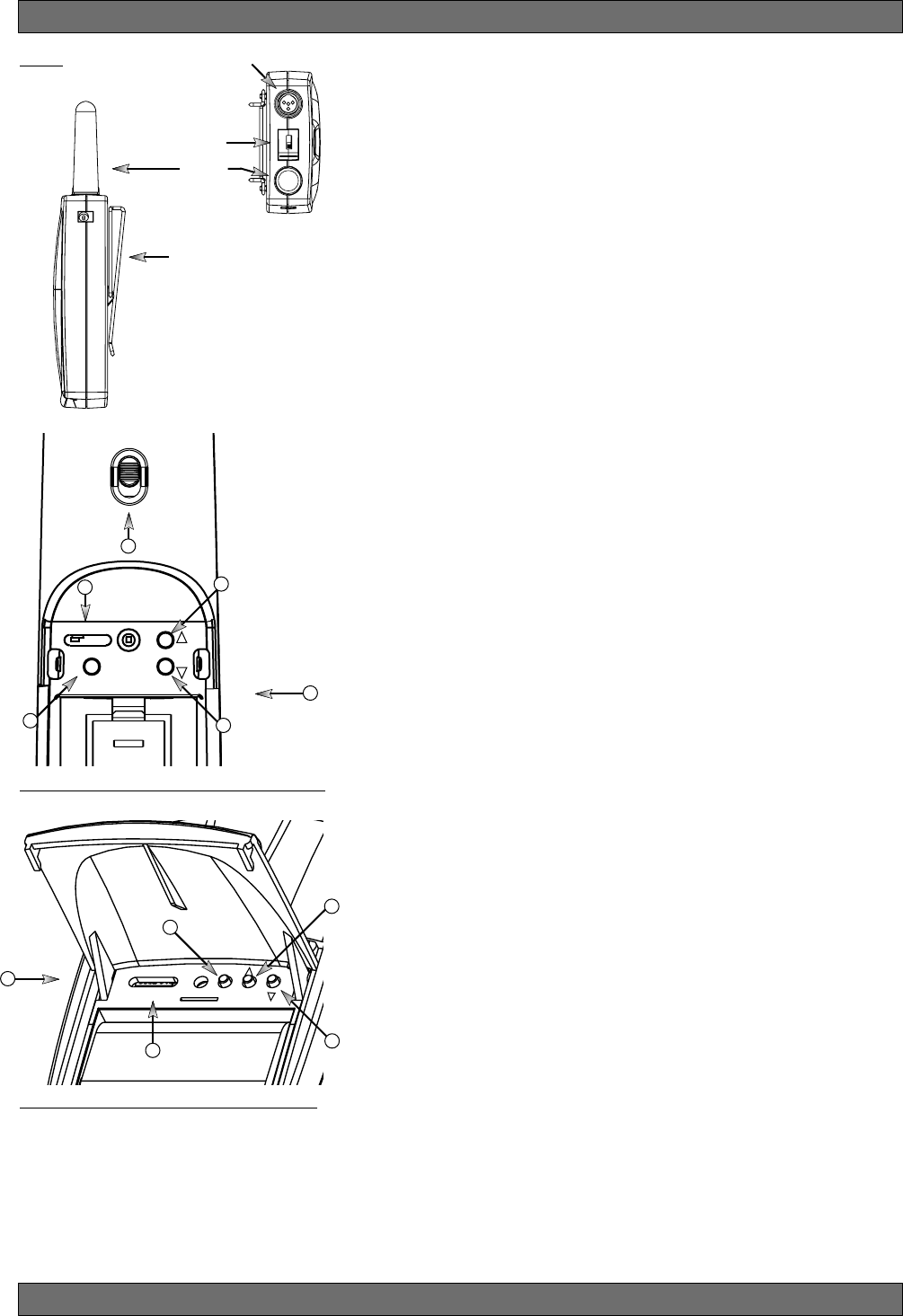
Fig. 4a
External
Switch
Fixed
Antenna
TA4F connector
Belt clip
1. Select Button
2. Up Button
3. Down Button
4. Programmable Control of External Switch
5. External Switch
6. Recessed control and battery compartments
Fig. 4c SW70T Transmitter Control Setting Buttons
6
Fig. 4b SW70H Handheld Control Setting Buttons
2
4
5
1
SELECT
ON ON ON
OFF MUTE ON
2.4 GHZ SMART SPECTRUM
3
SELECT
ON
ON
ON
OFF
MUTE
ON
2.4 GHZ SMART SPECTRUM
3
4
1
6
2
Transmitter Operation
13 Sabine 2.4 GHz Smart Spectrum® Wireless
E-SWM7000-OpGuide-031211.pmd - hto
4.2.2. Accessing Transmitter Controls
Control of all your transmitter functions is made using the Select button and
the Up/Down buttons. These control buttons are located inside the access
compartment on the beltpack or handheld transmitters.
Opening the Beltpack Transmitter Access Compartment:
1. Press down firmly with both thumbs on door handle (above Sabine
logo) and slide away from LCD.
2. Lift bottom edge of door slightly and continue pulling door down away
from LCD until the door opens fully (90-degree angle from transmitter
body).
Closing the Beltpack Transmitter Access Compartment:
1. Swing door down, flush with transmitter body.
2. With both thumbs pressing firmly on door handle (above Sabine logo),
slide door up toward LCD until door lip catches under main body of
transmitter, and bottom of door is flush with bottom of transmitter body.
Opening the Handheld Transmitter Access Compartment:
1. Grip door handles with thumb and index finger and lift up.
Opening the Handheld Transmitter Access Compartment:
1. Fold door closed until flush and locked in place.
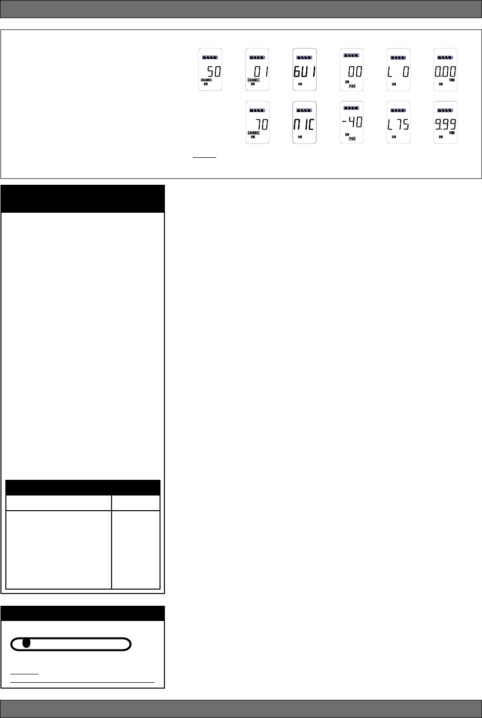
CHARGE: Illuminates when the transmitter battery is being charged
(i.e., when the charger is connected, either by direct plug-in or by plac-
ing the handheld mic in the Sabine charging clip).
BATTERY VOLTAGE LEVEL METER: Indicates measured battery volt-
age; the more segments illuminated, the higher the voltage, and the
greater the remaining battery life.
AUDIO LEVEL METER: Shows the audio output level of the transmitter
(affected by the pad setting).The last and largest segment indicates
clipping.
PARAMETER VALUE: In default mode this indicates the RF TRANS-
MISSION CHANNEL chosen for the transmitter. In conjunction with
the Select button (see figures 4b & 4c), this field will also display
battery run-time hours, or when a low frequency roll-off filter or an
attenuation (pad) is active (see Fig. 4g).
“TIME”: Displays when battery run-time hours are being displayed.
“MUTE”: Indicates output is currently muted.
“PAD”: Illuminates when the microphone pad is turned on. Use this if
the audio meter shows clipping.
“ON”: Illuminates when either the audio and RF transmission, or the
RF transmission only, are turned on.
“CHANNEL”: Illuminates in default mode to display transmission chan-
nel.
Fig. 4f: Start up Transmitter LCD display
Transmitter LCD
Display Indicators
Fig. 4d: SW70-T
Fig. 4e: SW70-H
Battery door handle
Turn off transmitter before changing battery(s).
BEFORE CHANGING BATTERY
Transmitter Operation
14
Sabine 2.4 GHz Smart Spectrum® Wireless
4.2.3. Adjusting Transmitter Settings
DEFAULT/CHANNEL: Press the Select button to enter Edit Mode, and re-
peat until the CHANNEL indicator flashes. In this mode, the Up/Down but-
tons will adjust Transmission Channel (1-70 available).
INPUT: (SW70-T Beltpack Transmitter only) Either “MIC” or GUI” for micro-
phone or instrument. You are required to choose the input in order to pro-
gram both the transmitter and the receiver to optimize the input settings.
Choosing MIC automatically selects the 75 Hz roll-off filter. You can choose
to remove that but the extended low frequency response of the SW70-T may
reproduce too much low energy for your system, so beware. Choosing GUI
automatically removes the 75 Hz roll off filter for that added bottom end in
your instruments. NOTE: You can manually change that filter setting as
needed.
PAD: Transmitter PAD setting. Press the Select button until the PAD indica-
tor flashes. The Up/Down buttons will adjust attenuation (SW70-H: 0, -6, -14,
-20 dB; SW70-T: 0, -3, -8, -11, -14, -17, -20, -30 dB). When any level of
attenuation is programmed, the default screen will illuminate PAD. See mar-
gin notes on this page and p.15 for settings instructions.
TIME: Battery Run-Time Hours. Selecting this option changes the display to
indicate the length of power-on time (hours and minutes) since the last
battery change or recharge.
NOTE: Battery run-time hours will reset when the transmitter (with battery in
place) is connected to a charger. In the case of the charger, run-time hours
will not start again until the charger is disconnected. You can manually reset
the run-time hours by pressing both the up and down arrows. Use this to
count hours when you use alkaline batteries.
LOW FREQUENCY ROLL-OFF: Selecting this option adds a 12 dB/octave
low frequency roll-off filter, starting at 75 Hz, to the audio output of the trans-
mitter. A roll-off filter may help reduce microphone handling noise, or other
unwanted low frequency content. Pressing the Up or Down button toggles
between the conditions of no filter (indicated in the display as L 0) or low roll-
off (indicated by L 75).
INTERNAL CONTROL OF EXTERNAL SWITCH: The recessed controls in-
clude a 3-position switch, which in turn determines how the transmitter’s
external two-position switch behaves (see figures 4a, 4b & 4h). From left-to-
right, the 3 positions of the internal switch correspond to the following exter-
nal switch operations:
1. ON/OFF. In internal position #1, the external switch acts as a typical on/
off switch. Use this setting if you trust the microphone user to switch the
microphone on and off as needed, and/or wish to conserve transmitter
battery life during down times. In the ON position the transmitter LCD
will display ON. Both audio and RF are on. In the OFF position the LCD
ON is no longer illuminated. Both RF and audio are off, and the battery
run-time hours meter is off. Note that Sabine’s squelch system pre-
vents any “popping” when switching the transmitter on and off. How-
ever, this protection causes a very short “power-on” delay in the reacti-
vation of the audio when the external switch is turned from OFF to ON.
Transmitter Operation
Transmitter LCD Display Cycle
Pressing the Parameter Select button
cycles the LCD through the following
screens. Individual screens appear for
approximately 4 seconds, during which
the function is editable.
NOTE: The SW70-H handheld micro-
phone has PAD settings of 0, -6, -14 and
-20 only. All transmitters are shipped at
the default setting of -14. Fig. 4g
Default
Screen
Channel
Select Battery Run-
Time Display
PAD
Select Low
Cut
Fig. 4h -
Programmable Control of External Switch
ON ON ON
OFF MUTE ON
Programmable External Switch
Handheld Microphone
PAD Settings
Your new Sabine wireless handheld micro-
phone is designed to accept a wide range of
input levels, from spoken word all the way
up to screaming vocals. In order to accom-
modate this broad range of inputs, the trans-
mitter has a PAD setting. Handheld mics are
set to a factory default of -14 dB, which is
the preferred setting for concert vocal per-
formance.
If you need more output out of a microphone
(the receiver LCD audio meter shows the mic
output level) then change the PAD settings
as described below. When any level of at-
tenuation is programmed, the default screen
will illuminate PAD.
Transmitter PAD Adjustment
(See Fig. 4b, 4f & 4g)
1. Use the Transmitter Select button to scroll
through functions until PAD flashes in the
Transmitter LCD.
2. Use the Up or Down buttons to select the
desired setting. Selection is stored after 3
seconds of inactivity.
3. Check to see if the receiver’s Audio Level
Meter stays out of the Clipping Zone.
Input
Select
~
~
~
or or
SW70-T ONLY
Suggested PAD Settings
PAD
Venue
Speech 0 dB
Loud speech
& vocal performance -6 dB
Strong vocal
performance (default) -14 dB
Very strong vocal
performance -20 dB
15 Sabine 2.4 GHz Smart Spectrum® Wireless
E-SWM7000-OpGuide-031211.pmd - hto
2. ON/MUTE. In internal position #2, the external switch acts as a typical
mute switch. Use this setting if you trust the microphone user to switch
the microphone audio output on and off as needed; it will not conserve
battery life in MUTE condition, but will allow the receiver to monitor and
display the RF signal strength in either switch position. In the on posi-
tion the default LCD will display ON. Both audio and RF are on. In the off
position the word MUTE is displayed in the LCD. The audio is muted
but the transmitter is still transmitting the RF signal, and the battery run-
time meter is running. There are no audible pops when switching the
transmitter between MUTE and ON. Switching from MUTE to ON will
instantaneously pass audio signal (there will be NO delay as with inter-
nal position #1).
3. ON/ON. In internal position #3, the external switch is disabled. The
transmitter (both RF and audio) is always on, and the word ON is al-
ways displayed in the transmitter LCD screen. Use this setting if you do
not want to allow the speaker or performer to turn off the transmitter, or
are worried that a transmitter may be accidentally turned off. Caution:
When your program is over we suggest you move this switch to another
setting so you can turn off the transmitter and save your battery. You may
also elect to remove the battery (though replacing the same one will
restart the run-time meter and affect its accuracy accordingly).
Once you have completed the transmitter setup, you are ready to work with your
receiver (see Section 5). First, however, let’s talk about the issues and solu-
tions concerning the source of transmitter power: the battery.
4.2.4. Transmitter Battery Management
4.2.4.1. Battery problems and Sabine solutions
Rechargeable Battery memory. Batteries that are repeatedly recharged
prior to a complete discharge may fail more quickly in subsequent uses.
This problem is usually referred to as “battery memory.” Fortunately,
Sabine’s innovative Tireless Wireless™ Charger takes steps to avoid
this problem, by automatically reconditioning the battery whenever its
intelligent diagnostics determine this is appropriate. For this process
to work best, we recommend that each charger be paired with a
specific transmitter for a “monogamous” charging relationship. If
you have multiple pairing options — i.e., multiple channel systems, we
recommend color- or number-coded charger/transmitter pairs. With
these precautions, use of Sabine’s Tireless Wireless™ Charger will
insure maximum life per battery charge, and also prolong the useful
multiple-charge life span of rechargeable batteries.
Battery life. Both handheld and beltpack transmitters can work with
disposable alkaline, disposable heavy-duty (manganese dioxide-car-
bon zinc), or rechargeable Nickel Metal Hydride (NiMH) batteries. We
specifically caution against using NiCad rechargeables due to well-
known battery memory problems, and specifically recommend using
the Sabine-supplied SWBC1 (C-cell for the handheld microphone) or
SWBAA2 (double-A for the belt pack) batteries. With the Sabine-sup-
plied rechargeable SWBC1, the typical recharge life of the handheld
transmitter battery is 8 hours (typically, an alkaline C-cell will give about
12 hours). The beltpack’s rechargeable SWBAA2 batteries will last about
8 hours per recharge (typically, alkaline AA batteries will last about 10
hours). NOTE: Heavy-duty batteries will fall somewhere in the middle,
between rechargeables and alkalines.
Transmitter Operation
Tech Tip
Transmitter/Charger Pairing
For best results, pair each charger
with a specific transmitter for a “mo-
nogamous” charging relationship.
Beltpack Transmitter
PAD Settings
The SW70-T beltpack transmitter has a broad
range of PAD settings, which allow you to
use it with almost any microphone or instru-
ment. As in all audio equipment, the setting of
the input level is crucial to achieving the best
sound quality. Setting minimal PAD levels (-3,
-6, or -10 dB) may produce a distorted sound
if you are using a high output microphone or
instrument. Conversely, setting a more ex-
treme PAD level (-40, -37, or -34 dB) may
require you to raise your system gain unnec-
essarily, resulting in a noisier output. Watch
the input meter on either the transmitter or the
receiver (see illustrations) and set your level
so there are at least three indicators illumi-
nated for normal program level, with an oc-
casional move to the fourth indicator. The fifth
and biggest indicator denotes clipping –
watch out! If you see clipping, choose a lower
pad setting (for example, from -10 to -14 dB).
Transmitter PAD Adjustment
(See Fig. 4c, 4f & 4g)
1. Use the Transmitter Select button to scroll
through functions until PAD flashes in the
Transmitter LCD.
2. Use the Up or Down buttons to select the
desired setting. Selection is stored after 3
seconds of inactivity.
3. Check to see if the receiver’s Audio Level
Meter stays out of the Clipping Zone.
Suggested PAD Settings
PAD
Venue
Low output microphones -10 dB
Standard mics & acoustic
instruments with low-gain
pickups -14 dB
Electric guitars with low-
gain pickups & mics with
higher gain -20 dB
Most standard electric
guitars -26 or -30 dB
Instruments with high-
gain pre-amps -34 dB
16
Sabine 2.4 GHz Smart Spectrum® Wireless
Sabine rechargeable battery advantages. Here are several more
good reasons why you can feel more confident about using recharge-
able batteries:
1. All transmitters report two types of battery status information. The
first report is the all-important voltage the battery is supplying. Sec-
ond, you’ll know how long the battery has been in use (battery run
time hours). Each receiver channel also receives telemetry infor-
mation from its associated transmitter, regarding the battery volt-
age, and displays the information in the receiver LCD (see figure
5b). When the voltage reaches a level indicating an estimated 30
remaining minutes of useful battery life, both transmitter and re-
ceiver automatically flash warnings in their LCD displays. As an
alternative means of anticipating battery depletion, you can check
the number of hours of use, by checking the transmitter LCD dis-
play (see Section 4.2.2 and figure 4g), or the Remote Control Soft-
ware.
2. The handheld microphone clip that we provide with each handheld
transmitter not only holds the microphone — it also can double as
an unobtrusive charger housing. Anytime the mic is parked in the
clip (and the clip is connected to the charger power supply), the mic
is being charged. As an additional safety margin against battery
failure, the mic placed in the powered clip gets its power from the
charger, not the battery, so it will work perfectly even if the battery is
completely dead.
3. Sabine’s intelligent charger circuitry detects the type of battery in
place within the battery compartment, and automatically turns off
the charger if the battery is not compatible with the charger.
4. The Tireless Wireless™ Charger detects when a battery is fully
charged, and turns off the charging cycle.
5. The Tireless Wireless™ Charger prevents futile attempts to resus-
citate dead batteries — if the battery is unresponsive, the charging
cycle is stopped.
6. Belt pack and handheld batteries can be recharged without remov-
ing them from the transmitters. Just connect charger plug to the
transmitter jack (see Fig. 4l).
NOTE: In the “most discharged” battery condition, a full recharge may
take up to 10 hours for a handheld C-cell, or 3 hours for the AA batteries
used with the belt pack transmitter. When in doubt, charge the batteries
overnight. Sabine’s battery-protection circuit will shut the charger down
when charging is completed.
Transmitter Operation
Turn off transmitter before
changing battery(s).
BEFORE CHANGING BATTERY
Your Sabine True Mobility® transmitter
comes with one or more rechargeable
NiMH batteries. For best results, charge
the battery for at least 8 hours before
using it for the first time. Please note
that the full charging potential of the bat-
tery will be achieved after the first 5
charging cycles have been completed.
NiMH rechargeable batteries are highly
resistant to “memory effect,” which af-
fects some other rechargeable batter-
ies. The included NiMH batteries will pro-
vide more lifetime charges and longer
battery life for each charge than many
other rechargeable batteries.
FIRST-TIME BATTERY CHARGING
NEDA: 14A ANSI: 14A IEC: LR14
Alkaline batteries must be one of following types:
SW70-T Beltpack Transmitters
2 “AA” size (14.5x50.5mm,
• NiMH Rechargeable (Sabine part #: SWBAA2)
• Alkaline: NEDA 14A - ANSI 14A - IEC LR14
• Heavy Duty batteries (NOT recommended)
)
SW70-H Handheld Microphones
1 “C” size (26x50mm,
• NiMH Rechargeable (Sabine part #: SWBC1)
• Alkaline: NEDA 14A - ANSI 14A - IEC LR14
• Heavy Duty batteries (NOT recommended)
)
Acceptable Batteries for use with
Handheld & Beltpack Transmitters
IMPORTANT BATTERY INFORMATION
WARNING! DO NOT USE
Alkaline Rechargeable Batteries
Alkaline “AA”
Rechargeable
Batteries
Alkaline “C”
Rechargeable
Batteries
Alkaline
Rechargeable Alkaline
Rechargeable
17 Sabine 2.4 GHz Smart Spectrum® Wireless
E-SWM7000-OpGuide-031211.pmd - hto
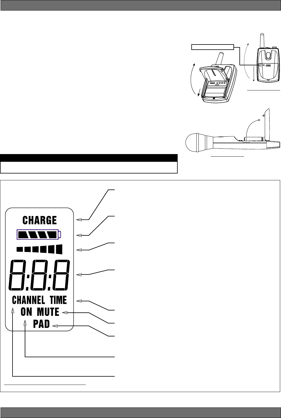
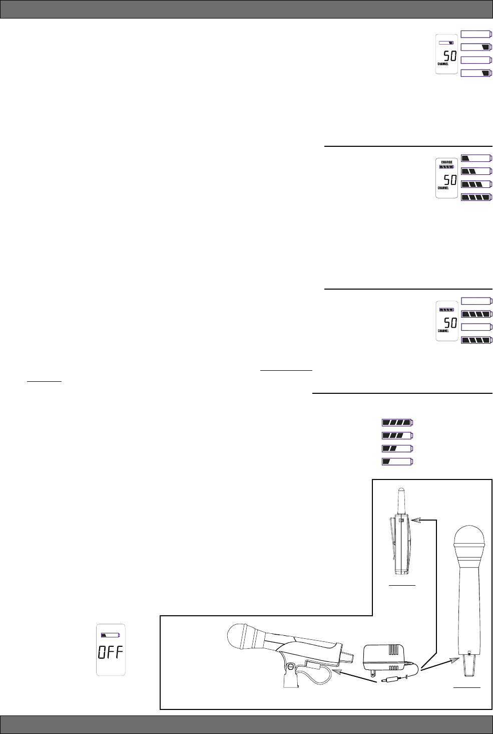
4.2.4.2. Charging Your Batteries
Equipment Connections. Each SW70T or SW70H transmitter comes
equipped with an SWC-POWR Tireless Wireless™ plug-in charger (see
Fig. 4l). In addition, each SW70H comes with its own battery-charging
mic clip (SWC70-CL). The SWC-POWR charger can be plugged directly
into either the transmitter or into the clip. A Sabine rechargeable battery
(SWBC1) will charge whenever the mic clip is connected to the Sabine
SWC-POWR charger and the handheld is properly placed within the
mic clip.
Charging Indicators. Much like your cell phone, the transmitters will let
you know the charging status of the battery. When the battery is charg-
ing, the battery meter will flash to indicate the relative level of the charge
— one, two, three or four elements will flash (see Fig. 4i).
Once the battery is fully charged, all four elements in the battery meter
will flash. This indicates that the charging circuit is no longer on (see
Fig. 4j).
NOTE: The right-side indicator segment will flash for several minutes
when charging is first attempted (see Fig. 4h). The lower the battery
level, the longer this initial “testing/not charging” flashing sequence will
continue. During this time, the Tireless Wireless battery circuit is evalu-
ating the suitability and charge status of the battery in place. When it has
completed its evaluation, it will either commence the progressive flash-
ing depicted in figure 4i (CHARGING), or continue to flash (TESTING/
NOT CHARGING). All segments flashing in unison signifies that the
battery is fully charged (see Fig. 4j).
These same indications will also be displayed on the receiver LCD,
and on the Remote Control Software screen.
NOTE: The Tireless Wireless battery charger will only charge NiMH
rechargeable batteries. If you place any other kind of battery in the
transmitter, and then attempt to charge it by connecting the charger, the
Tireless Wireless circuit will detect the type of battery and will not begin
charging. Again, the battery indicator on the transmitter will flash the
right-side element indicating testing/no charging (see Fig. 4h).
Battery Warnings. When the transmitter battery voltage drops below a
critical threshold, the battery icon (which normally displays the voltage
level) will begin to flash. This will occur on the transmitter and receiver
and is an indication that you need to replace the battery, or charge it by
placing the handheld mic in the charger clip. NOTE: Microphone will still
transmit audio when placed in clip. Alternatively, you can connect the
charger directly to the transmitter using the built-in charger jack located
on the side of the beltpack transmitter and near the antenna on the
handheld transmitter (see Fig. 4l). If the battery is not changed or re-
charged, the transmitter will eventually turn off (see Fig. 4k).
Transmitter Operation
Fig. 4l: SWC-POWR plug-in charger for SW70 Series Transmitters & SWC70CL Mic Clip
Fig. 4h: TESTING/NOT
CHARGING
Right-side battery indicator
segment will flash to indicate
that the battery is being
tested. This occurs prior to
charging a NiMH battery and whenever a non-
rechargeable battery is placed on charge.
Charging is not occuring when indicator lights
in this fashion.
Fig. 4j: FULL CHARGE
Battery indicator segments
will flash in unison to indi-
cate that the battery is fully
charged.
NOTE: Battery can be left
connected to the charger and will receive pe-
riodic maintenance charging.
Fig. 4i: CHARGING
Battery indicator segments
will flash progressively start-
ing from the relative charge
state of the battery. This ex-
ample depicts a fully dis-
charged battery being charged. As the charge
progresses, left-side segments will remain vis-
ible as right side segments continue to flash,
until all segments are visible. At that point, all
segments will flash on and off in unison (see
Fig. 4j).
Fig. 4k: Battery CHARGE LEVEL displays
NOTE: When the battery has reached
a specific discharge level, the transmit-
ter will automatically
turn off, and the trans-
mitter LCD will display
the message at right.
Very Low (Flashing)
Very Used
Partially Used
Fully Charged
SWC70CL
(Mic Clip for SW70H)
SW70T
SW70H
18
Sabine 2.4 GHz Smart Spectrum® Wireless
5. RECEIVER OPERATION
5.1. LCD Display.
The receiver LCD display is shown below (Fig. 5b). Two-channel receivers
feature two LCDs, one for each channel. The display provides a snapshot
report of the condition of your wireless channel, including battery status infor-
mation sent from the transmitter by telemetry.
The right two-thirds of the display primarily shows status information regard-
ing the condition of your receiver channel, as follows:
Receiver Operation
Fig. 5a: SW72R front panel
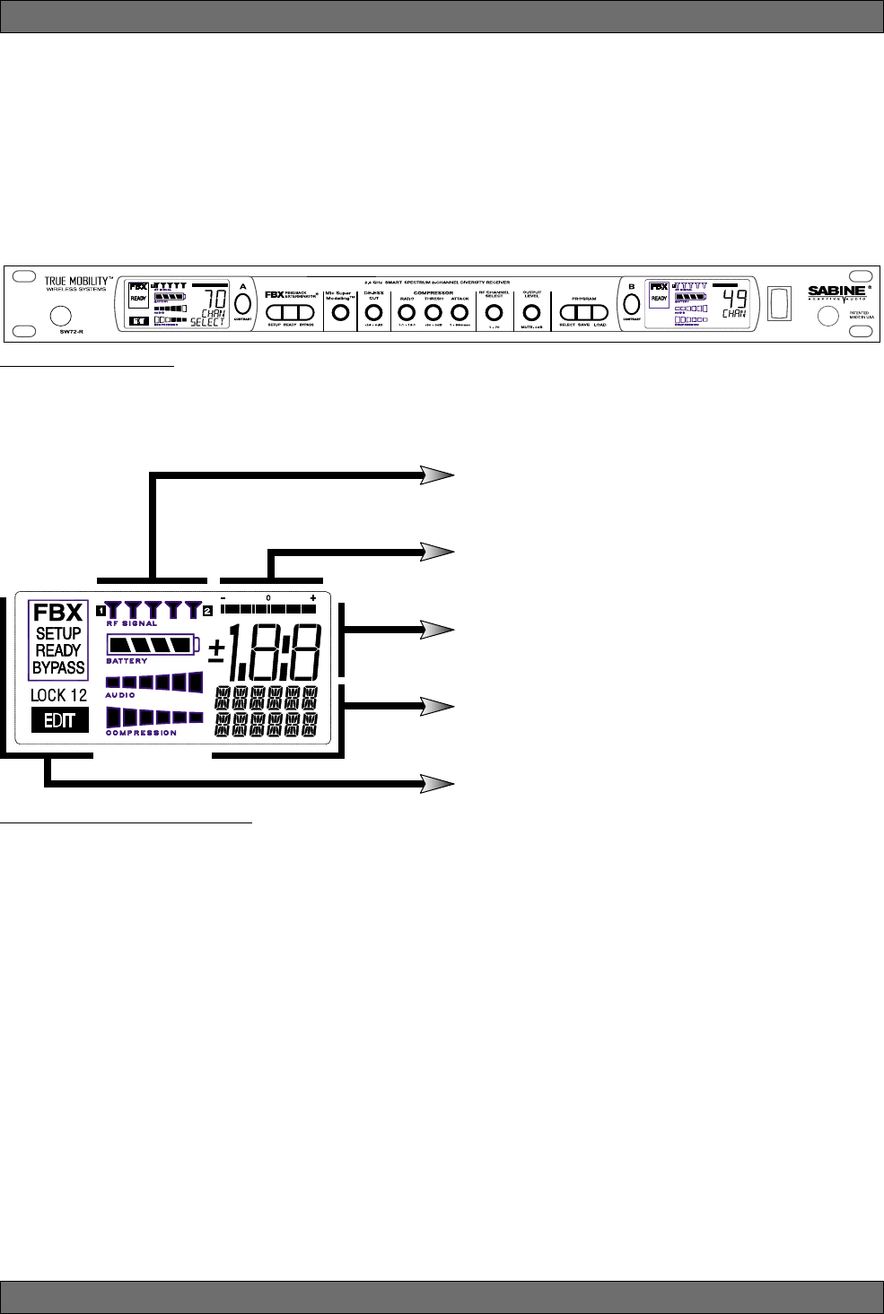
Fig. 5b: Receiver LCD Compete Display
Receiver LCD Status Bars
Relative Position Indicator
Function Value Display
Function Display Messages
FBX, Lock and Edit Status Indicators
19 Sabine 2.4 GHz Smart Spectrum® Wireless
E-SWM7000-OpGuide-031211.pmd - hto
Receiver Operation
Diversity Status: Either 1 or 2 is lit, showing the active antenna.
RF Signal Strength Indicator: Indicates presence of RF (from transmitter, or
external sources) on the chosen reception channel. The greater the number of
illuminated icons, the stronger the RF signal detected.
Compression Meter: Shows the active gain reduction applied to the receiver
channel’s audio output.
Audio Level Meter: Shows the audio input level (received audio signal).
Battery Voltage Level Meter: Indicates the battery voltage of the correspond-
ing transmitter; the more segments are illuminated, the higher the voltage, and
the greater the remaining battery life.
Receiver LCD Status Bars
FBX, Lock and Edit Status Indicators
FBX Status: SETUP is illuminated while the receiver is in SETUP MODE.
READY is the normal operational mode, indicating SETUP has been performed
and FBX filters are active. BYPASS indicates the audio signal is NOT going
through FBX filters (but all other DSP processing is active).
Front Panel Lock Status: LOCK 1 indicates all front panel controls are locked
to prevent intentional tampering, or accidental programming. LOCK 2 indicates
a subset of controls are locked, allowing selected others to be adjusted with
software only. Default LOCK 2 setting locks out all functions except FBX and
Program Load.
Edit Status: In a 2-channel receiver, this field illuminates when the corre-
sponding Channel Button is pushed, indicating Controls are assigned to this
channel.
Firmware Version: Displays for 2 seconds on power up; shows the receiver
firmware version.
Transmitter Battery Low: You have 15 minutes or less to change transmitter
batteries.
Mute: Transmitter muted; the transmitter on/off switch is set to mute.
Front Panel Locked: Front Panel is locked and the selected function cannot be
edited. See Appendix D for an explanation of front panel locking.
De-Esser: The De-Esser is actively reducing sibilance.
Function Display Messages
20
Sabine 2.4 GHz Smart Spectrum® Wireless
Receiver Operation
Fig. 5d Tweek-n-Peek example
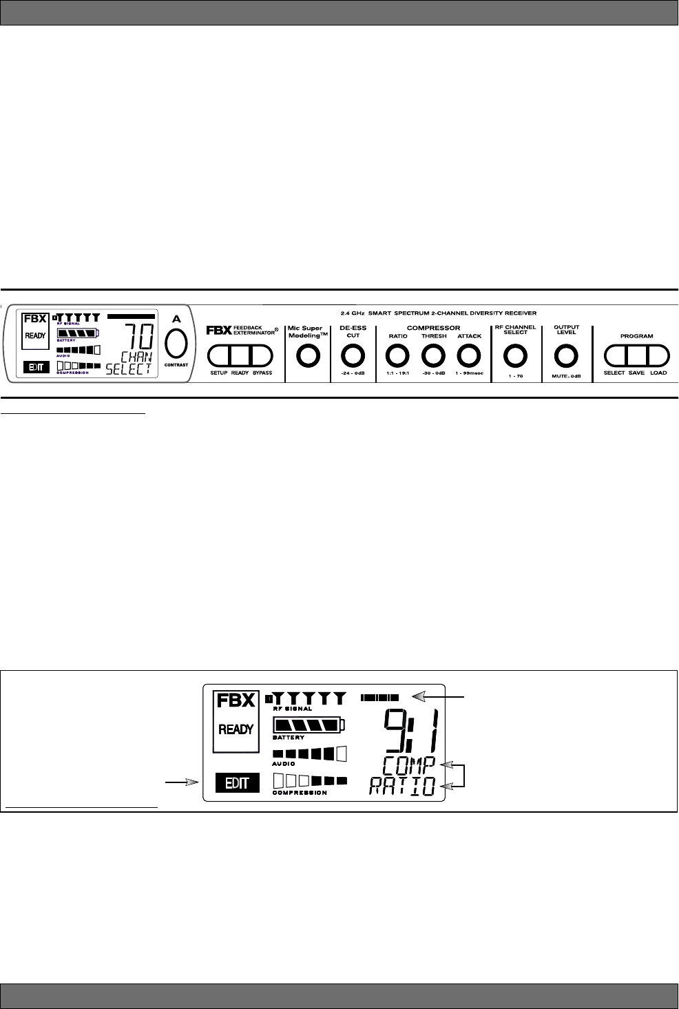
Relative Position Indicator
In our compressor Ratio example, if
you are at a ratio of 9:1, about the
middle of the range, the RPI will
display about one half of the bar.
Function Display
The Function display will show COMP
on the first line and RATIO on the
second.
EDIT will light in the
channel display of the
channel being edited.
Fig. 5c Sabine Tweek-n-Peek
5.2. Parameter Control & LCD Display
5.2.1. One set of Controls for 1 or 2 Channels
Whether you have a one- or two-channel SWM7000 series receiver is appar-
ent by the number of LCD displays on the front panel. However, only one set
of control knobs is provided for either one- or two-channel receivers. Note
that in a 2-channel receiver, this set of controls is shared, and assigned to a
channel by pushing either the A or B Channel Select button (see Section
5.2.2). Your SWM7000 Series receiver uses Sabine’s Tweek-n-Peek™ digi-
tal control system. Whenever you turn a control knob one click, the associ-
ated function is shown on two lines of text display in the LCD. The large
numeric display will indicate the current parameter value. Additional turns/
clicks change the parameter setting and display the value as the change is
made. After a few seconds of inactivity, the LCD will revert to its default display
(RF channel).
Sabine’s Tweek-n-PeekTM
Whenever you turn a control knob one click, the name of the corresponding
function is shown and the current edit setting is displayed on the LCD. This
applies for all the front panel knobs.
For example, if you turn the Compressor ratio knob one click, you will see the
current compression ratio in the Settings Display. The Text display will show
COMP on the first line and RATIO on the second. Subsequent turns will edit
that setting up or down, depending on the direction you turn the knob.
Since the control knobs are continuous rotary encoders with no end points,
the Relative Position Indicator (RPI) is a handy way of seeing where you are
in relation to the full range of the knob in question. In our compressor Ratio
example, if you are at a ratio of 9:1, about the middle of the range, the RPI will
display about one half of the bar. NOTE: The setting range of each control is
printed on the front panel below each knob.
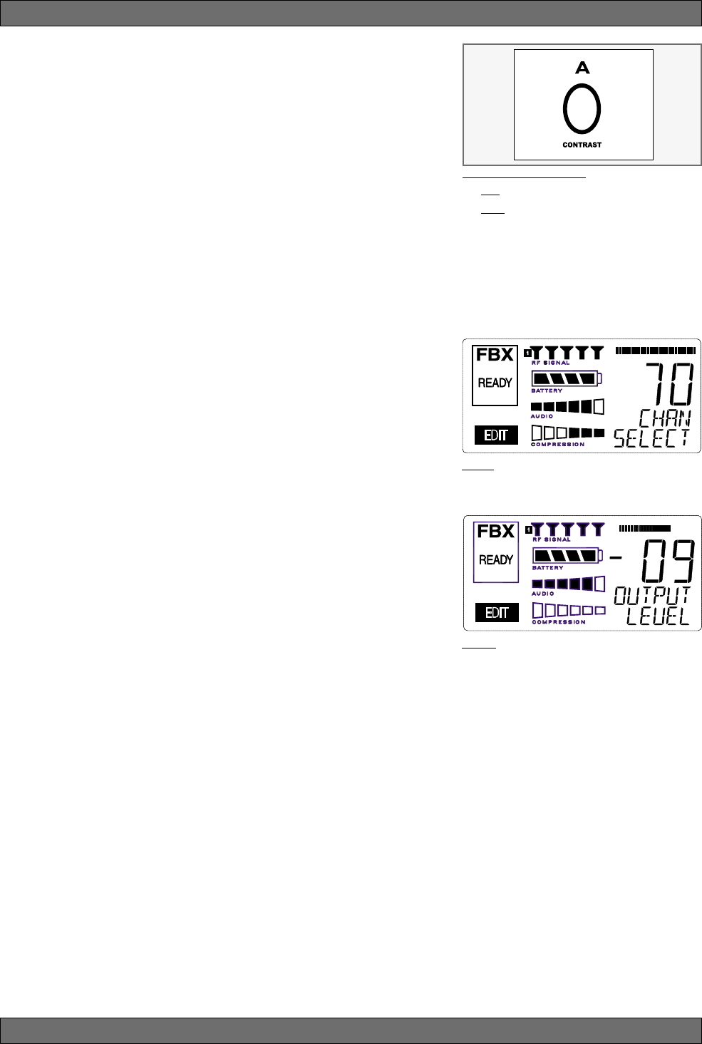
5.2.2. Channel Select / Contrast Button.
The elliptical button immediately adjacent to the LCD has multiple functions.
First, it adjusts the LCD contrast and viewing angle. Change the degree of
angle by pressing and holding the button down. The adjustment range will
cycle in a continuously reversing loop — when it gets to the maximum value
it reverses and begins to decrease in value. You can stop holding the button
down and initiate single button pushes to advance (or decrease) the con-
trast setting incrementally.
21 Sabine 2.4 GHz Smart Spectrum® Wireless
E-SWM7000-OpGuide-031211.pmd - hto
Receiver Operation
Fig. 5g
Fig. 5f
Fig. 5e: Contrast button:
Tap to select which channel to control
Hold to adjust contrast and viewing
angle. Range of value is 1 - 30, 15 is
default.
In addition, the Contrast/Channel Select button has another function, in 2-
channel receivers only (SWM72-R or SWM72-NDR). Such units feature two
LCDs and two Contrast/Channel Select buttons. A single (without continuing
pressure) push assigns all Parameter Control knobs to the selected chan-
nel. The button will light, the associated LCD will brighten, and the word EDIT
will appear in the lower left of the LCD, all indicating the active edit channel.
For the active channel, turning any Parameter Control knob will first display
(one click) and then adjust (subsequent turns) the settings of the function
selected, indicating the changes in the Settings Display. For the inactive
channel, turning any Parameter Control knob will display the current setting
in that channel’s Settings Display. The channel must be activated in order
to change settings.
5.2.3. Special LCD Display Messages.
In addition to the Status and programmable information discussed above,
the text lines of the LCD Settings Display may also (under certain circum-
stances) automatically override other displays. The conditions when this will
occur and the messages displayed are shown on page 19.
5.3. RF Channel Select
Range = 1 to 70 Choose the RF channel for this system. The transmitter
must have the same channel selected. Turn the RF CHANNEL SELECT knob
until the desired channel is displayed on the LCD. See chart (Appendix E) for
exact frequency of each channel.
NOTE: Dual channel receivers will not allow you to select the same RF chan-
nel for both channels.
NOTE: Front panel RF Signal display will only register Sabine transmitters. It
will not show RF interference. Use the RF Scan function in the software to scan
for potential RF interference (see Section 13.4.2.5).
5.4. Output Level
Range = MUTE to 0 dB Adjust the output level to match the input character-
istics of the downstream component. Each tick of the output level knob adjusts
the level by ½ dB. The LCD displays this in 1 dB resolution, so it takes two ticks
of the knob to change the output level value on the LCD.
The output level varies from microphone level to line level, so if you are patch-
ing the receiver to the mic level input of a mixer, turn down the level to avoid
overdriving the mixer input. Minus 15 dB is a good place to start. If you are
patching into a line level device, turn up the receiver output. For best results,
follow the golden rule of gain structure: maximize gain at early stages in the
signal path, to minimize noise that will be accumulated and amplified by add-
ing late-stage gain.

22
Sabine 2.4 GHz Smart Spectrum® Wireless
5.5. Receiver Antenna Placement
One of the biggest potential problems in any wireless system is RF interfer-
ence. Understanding wave interference patterns will help you to place and
orient your receivers and antennas properly, and thereby reduce the likelihood
of RF interference.
Your SWM7000 series receiver ships with two standard coaxial bipole anten-
nas. Each antenna picks up in a donut-shaped (toroidal) pattern, more or less
equally in all directions, with null points directly above and below.
5.5.1. Multi-path Interference
Like sound waves, radio waves are subject to wave interference patterns
produced by reflected or delayed waves combining with direct, unreflected
waves, converging upon a receiving antenna simultaneously. In the RF world
this phenomenon is called multi-path interference. As with audio comb
filtering, radio waves can combine additively or subtractively. Thus, mounting
an antenna close to a reflective surface can result in poor reception. For
example, if weaker than expected reception occurs, and the receptive part of
the antenna (the top 3 cm) is close to a reflective surface (wall, large metal
objects, etc.), you might improve reception simply by repositioning, or re-
aiming, the antennas.
In some situations — for example, those with difficult lines-of-sight, or when
transmitters and receivers are separated by a wall, or when receiver place-
ment options are limited — an extension antenna may be necessary to
guarantee reliable reception. Please refer to Section 12 for information about
the advantages and use of Sabine’s SWASS-EXT Extension Antenna Kit.
5.5.2. Receiver & Antenna Placement Tips
1. When possible, maintain line of sight from transmitter to receiver.
Consider the potential range of transmitter “roaming,” and locate your
receiver accordingly. If direct line of sight proves impossible or difficult,
consider using Sabine’s low-profile, active Extension Antenna Kit
(SWASS-EXT), which boosts the signal strength, extends the maximum
distance from transmitter to receiver, expands and focuses antenna
sensitivity, and allows antenna and receiver to be positioned further
apart or in separate rooms.
2. Decide on front or rear panel antenna mounting (to maintain line-of-
sight path). Antennas typically mount on the rear panel of your receiver,
but the included accessory SWA700 front mounting kit can be screwed
onto the front and connected via jumper to the back panel terminals.
When mounting receivers in a rack that is deeper than the receiver,
move the antennas to the front for improved reception. For any rack
mounted receiver, try to keep the top 1.25 “ (3 cm) of both antennas
extended outside the sides of the rack (see Fig. 5h). Non-rack mounted
receivers should be oriented so that the antennas face the transmitters.
3. Maximize the distance between the receiver and light sources, such
as fluorescent bulbs or neon signs, which may emit very short-range,
broadband interference. These light sources should not be a problem
in normal circumstances, but, as a cautionary preventative, we recom-
mend a minimum distance of 3 meters (10 feet) between them and any
receivers or extension antennas.
4. Note the placement of any microwave ovens in the immediate vicin-
ity. Place any receivers or extension antennas as far away as is practi-
cal from microwave ovens.
5. Mount receiver antennas at 90 degrees to one another, leaning away
at 45 degree angles, in the same plane. This will decrease the likeli-
hood that one antenna will be susceptible to the same orientation-
specific directional or multi-path problems that may affect the other one.
Receiver Operation

23 Sabine 2.4 GHz Smart Spectrum® Wireless
E-SWM7000-OpGuide-031211.pmd - hto
6. When using multiple receivers, try to maintain at least 1 foot (30 cm)
distance between antennas from different units. If you are rack-mount-
ing multiple receivers, you may want to avoid spacing them in adjacent
rack spaces, to maintain distance between antennas. When such an-
tenna spacing proves difficult or impossible, we recommend using
Sabine’s Antenna Distribution Amplifier (Sabine SWA6SS), which can
help manage antenna configurations and, more importantly, improve
system-wide interference rejection. The SWA6SS works with up to six
receivers.
7. In very rare instances, poorly shielded or malfunctioning computers
or digital effects units may cause RF interference. You can test whether
such units are the sources of such interference by switching them off
one at a time, and determining if interference rejection improves.
8. Turn on your system one component at a time, beginning with the
first receiver. If you don’t have a computer handy, keep all other receiv-
ers and transmitters switched off for the time being.
9. Use the RF Scan function included in the Remote Control Software.
This will give you a picture of the potential interference in your area, both
real-time and over time. Please refer to Section 13.4.2.5. for information
on Sabine Remote Control Software’s Automatic RF Scan function, which
will automatically determine the best RF channels to use.
10. Maintain a minimum distance of at least 3 meters (10 feet) between
transmitters and receivers or extension antennas. This can solve
many anomalies.
11. Be careful not to set more than one transmitter to the same channel;
each paired transmitter and receiver should be set to unique corre-
sponding channels, until all channels are receiving clearly and cleanly.
12. Once the physical placement of your receiver(s) and antenna(s) is
decided, proceed with the remainder of the setup process.
Receiver Operation
24
Sabine 2.4 GHz Smart Spectrum® Wireless
Fig. 6a
6. MIC SUPERMODELING™
6.1. Introduction
Microphones come in a dazzling variety of shapes, sizes, polar patterns, fre-
quency response curves, phase response curves, etc. Few things arouse as
much passion amongst audio engineers as discussions about what micro-
phone to use in a given application. Sound rental companies and recording
studios proudly tout their impressive microphone collections, and singers
frequently favor a certain brand and model number as “perfect for my voice.”
The only viable “please everyone” strategy is to stock a wide assortment of
microphones. This is far easier for wired microphones than for wireless.
Changing a wired microphone is as simple as disconnecting one mic and
connecting an alternative — the same cable and same microphone stand
allows easy interchangeability. At worst you might have to exchange micro-
phone clips along with the microphones themselves.
For wireless microphones, however, the situation is not so simple. With differ-
ent transmission frequencies, different proprietary designs, different types of
connectors (microphone to belt pack transmitter), and the matched-set nature
of transmitters and receivers, changing a microphone/transmitter is far more
complex.
Sabine has a better idea — Sabine’s proprietary Microphone SuperModelingTM.
With digital technology, it’s possible to start with the sonic signature of a high
quality microphone (such as Sabine’s standard condenser and dynamic cap-
sules used in our SWM7000 handheld series systems), and emulate the
characteristics of other popular microphones—all at the twist of a knob. You
won’t have to change microphones, cables, connections, or receivers, inter-
rupt a performance, or even get up from your mixing chair! Best of all, you will
have an instant answer to a variety of demands from singers and speakers for
their favorite microphone — even if they pass the microphone around.
6.2. Emulation Choices
Each Sabine SWM7000 receiver (SW72-NDR, SW71-NDR,SW72-R, SW71-R)
comes equipped with 7 different SuperModel microphones available per chan-
nel. Four of these (Shure SM-58, Shure Beta 58, Audio Technica ATM 41A, and
AKG D-3800)* are designed for use with either of Sabine’s dynamic handheld
microphone/transmitters (SW70-HD3 or SW70-HD5). The remaining three
(Shure Beta 87A, AKG C535EB, and Audio Technica ATM 89R)* are designed
for use with Sabine’s condenser handheld microphone/transmitter (SW70-
HC). In addition to these SuperModeling choices, you may prefer to use Sabine’s
high quality microphones “just the way they are;” i.e., without emulation.
Telemetry information sent by the handheld transmitter to the corresponding
receiver (or receiver channel for a 2-channel unit) identifies the type of trans-
mitter, and loads the appropriate emulation library. Note that beltpack trans-
mitters also send telemetry that turns off the Super Model option, as this fea-
ture is designed to work only with handheld microphone/transmitters.
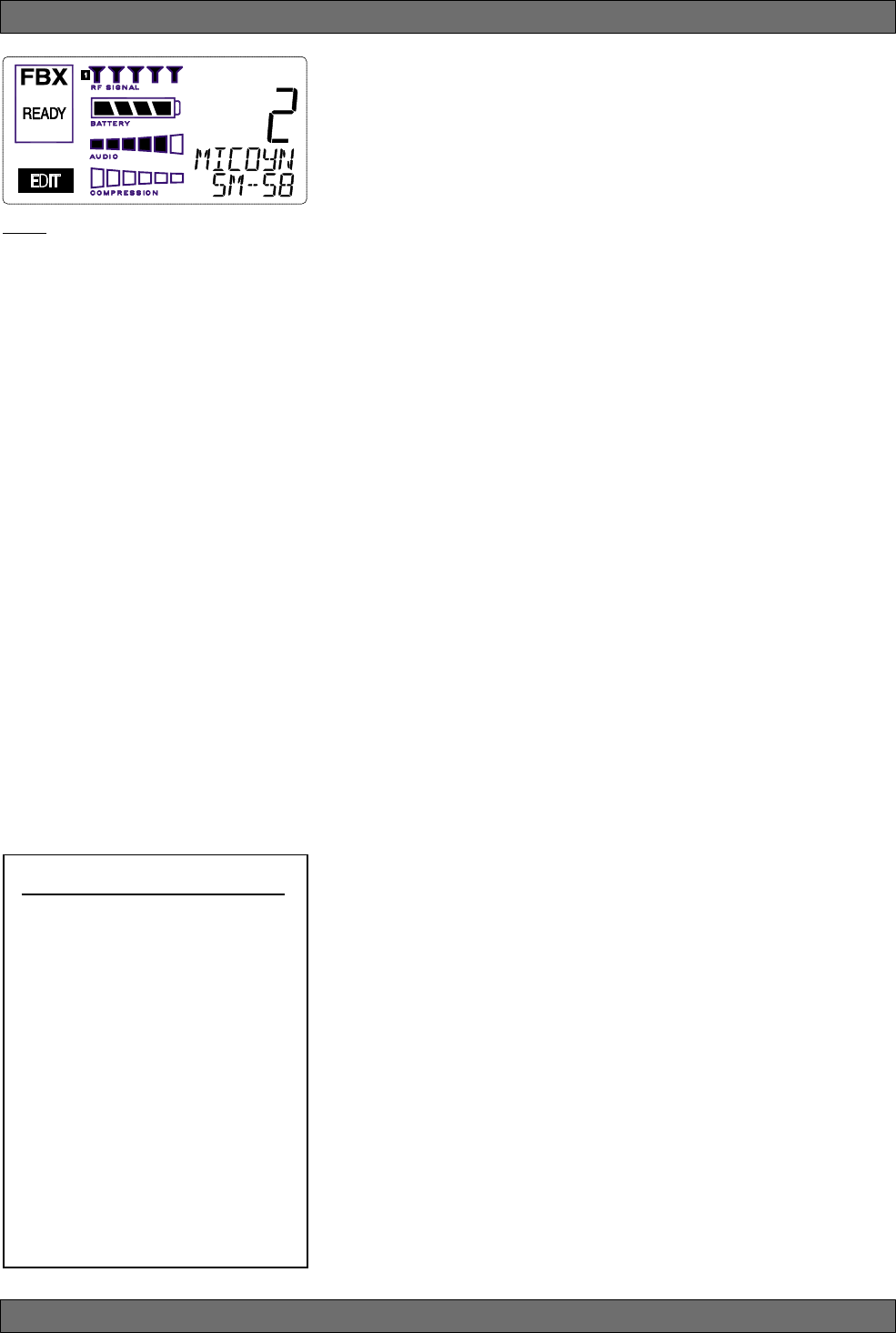
6.3. Mic Modeling Front Panel Control
Simply turn the parameter control labeled “Mic SuperModelingTM” to scroll through
and select the microphone you wish to emulate. The first click of the knob will
show the current setting, without changing it; additional turns will change the
emulation that is active. The top text line of the Settings Display will read either
MICDYN (dynamic) or MICCON (condenser) depending on the telemetry infor-
mation sent by the handheld; the bottom line will display the microphone being
emulated. Note that one choice is to bypass modeling, and simply utilize the
excellent quality of the Sabine microphone capsules. In this case the bottom
text line will simply read OFF. Finally, whenever telemetry information indicates
that a belt pack transmitter is the RF source, or if a handheld transmitter is
replaced by a belt pack with the same receiver (or some such other unpredict-
able event transpires), the Settings Display will read MICMOD/OFF whenever
the Mic Modeling knob is turned.
Mic SuperModeling™
Sabine Mic SuperModelingTM
SuperModelingTM Dynamic Models*:
- Shure SM-58
- Shure Beta-58A
- AKG D-3800
- Audio-Technica ATM 41a
SuperModelingTM Condenser
Models*:
- Shure Beta 87A
- AKG C535 EB
- Audio-Technica ATM 89R
*
Company names, product names, and
trademarks listed as modeled are the prop-
erty of their respective owners and are used
only to identify evaluated microphones used
to develop digital processing; they in no way
imply association, endorsement, or approval
by any named manufacturer.
25 Sabine 2.4 GHz Smart Spectrum® Wireless
E-SWM7000-OpGuide-031211.pmd - hto
There are no modeling settings for lavalier or headset microphones — mic
placement makes these an unrealistic choice for modeling. NOTE: other
lavalier microphones can be used with the Sabine Beltpack Transmitter.
6.4. Future Microphone Modeling Choices
When Sabine adds to the library of “virtual microphones” that are modeled by
the receiver DSP, these will be made available as a firmware upgrade from the
Sabine web site, www.Sabine.com.
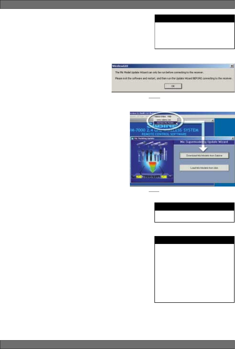
6.4.1. Mic Model Upgrade Instructions
New Mic SuperModelingTM “virtual microphones” can
be downloaded easily using the remote control soft-
ware on your PC. NOTE: The Mic SuperModeling Up-
date Wizard can be accessed only from the initial
software startup menu (prior to connecting to a re-
ceiver or entering Demo/Edit Mode). If you have al-
ready connected and attempt to access the Upgrade
Wizard, the message box at right will appear (Fig. 6b):
To download new mic models:
1. With your PC connected to the Internet, pull down the Sabine
Online menu in the software menu bar and select “Add
New Mic Models.”
2. Click the “Download Mic Models from Sabine” and follow
the dialog box instructions.
3. The last dialog box will allow you to either connect to a
receiver and update the mic models on that receiver, or
cancel and complete the upgrade process at a later date.
Note that this dialog box will show the actual file path of the
new mic model file.
Upgrading from a disk or previously downloaded files:
Mic SuperModeling™ files already downloaded can be flashed
into your receiver using the second option “Load Mic Models
from disk.” Clicking this button opens a dialog box (default di-
rectory is your “Sabine” directory).
NOTE: File name will always be “micmodels.smm” and will
include all mic models available up to the date the file was downloaded.
Mic SuperModeling™
Fig. 6b
Fig 6c
NOTE
A very short crossfade of the audio sig-
nal occurs when switching between mic
models. This ensures no digital artifacts
will occur when you change the sound
of the mic.
NOTE
Mic SuperModelingTM is not available us-
ing beltpack transmitters.
CHANGING AUDIX CAPSULES
Sabine's Mic SuperModeling™ function
requires a baseline characteristic for the
capsule in use. Therefore, after chang-
ing capsules, you will need to “tell” the
transmitter which capsule is now at-
tached.
NOTE: this is only necessary when the
capsule is changed.
See Appendix G for instructions on how
to reset your transmitter after changing
Audix capsules
26
Sabine 2.4 GHz Smart Spectrum® Wireless
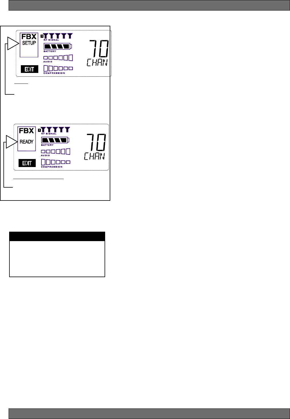
FBX Feedback Exterminator
FBX SETUP NOTE
LCD “READY” Flashing
As you get close to the end of the setup
procedure, READY will begin to flash on
the LCD. Stop raising the gain! The
FBX will now go into Ready Mode.
7. FBX FEEDBACK EXTERMINATOR®
SETUP Indicator
Fig. 7a
Fig. 7b: READY Indicator
NOTE: make sure READY is displayed before
using your system for a performance.
7.1. FBX Introduction
There are two types of FBX filters, fixed and dynamic. Both operate automati-
cally. There is no audible difference between fixed and dynamic filters in
terms of sonic purity; the difference arises in their application.
7.1.1. FBX Fixed Filters
Fixed filters are set automatically during the FBX SETUP and will not change
frequency until manually reset.
7.1.2. FBX Dynamic Filters
Dynamic FBX filters also set automatically, but can change frequency, on a
rotating basis, as the need arises.
7.1.3. Balancing Fixed & Dynamic Filters
Each channel of your SWM7000 wireless receiver offers a total of 10 FBX
filters (combined fixed and dynamic), which can be used as needed to
exterminate feedback. The default setting of 7 Fixed and 3 Dynamic can be
changed to 8 Fixed and 2 Dynamic using the DIP switches on the back of
your receiver (see Appendix D FBX Configuration DIP Switch), or to any
configuration using the Remote Control software (see Section 13).
If you follow setup instructions for setting FBX filters, your receiver will
automatically exit SETUP mode (enter READY status) after all Fixed filters,
and the first Dynamic filter, have set. In the default condition, this means
you will have set eight filters (seven Fixed and one Dynamic), with two
Dynamic filters still unset and remaining on standby alert. If you wish to
set fewer filters, press the READY button before SETUP automatically
exits, after you have set enough filters to safely achieve your desired gain
level. In that case, in the factory default condition, you will reserve three
unset Dynamic filters for standby.
7.1.4. FBX Filter Width
Sabine’s experience and testing with filters and sound quality along led us to
decide upon a default FBX filter width of .10 (one-tenth) octave as the optimal
notch width, able to eliminate feedback without affecting music programs. If,
with all filters properly set, feedback is still a problem, FBX filters may be set
to .20 (one-fifth) octave width. This wider filter setting will help to better elimi-
nate feedback trouble areas, but may also affect music programs slightly.
Therefore, the wider setting is generally considered to be appropriate where
speech (less demanding than music) is the primary application of the Sabine
Wireless system. You can globally change FBX filter width by repositioning a
rear panel DIP switch, to change from .10 to .20 octave (see Appendix D FBX
Configuration DIP Switch), or by adjusting filter width using the True Mobility®
Remote Software (which allows a range of widths from .01 to 1.0 octave).
You may also mix filter widths, either by adjusting individual filter widths
using the Remote Software, or by changing the DIP switch position during
setup. The width of any set filter will always be determined by the position of
the switch at the time the filter is created.
7.2. FBX Set Up
Follow these easy steps to obtain the maximum gain and protection from
feedback. Sabine FBX employs a very fast and quiet setup mode to make it
easy to use.
1. Place the speakers in the positions where they will be used during the
program.
2. If there is any equipment with a noise gate in the signal path, you MUST
DISENGAGE the noise gate(s) prior to the setup procedure. You may
reengage these noise gates upon conclusion of your FBX setup.
3. Patch your Sabine receiver into the mixer or amp channel. Set the amp
master output gain to a normal operating position.
NOTE: The level of your power amplifier should be set to a level that allows
a healthy gain structure prior to the amplifier. If your amplifier is turned up
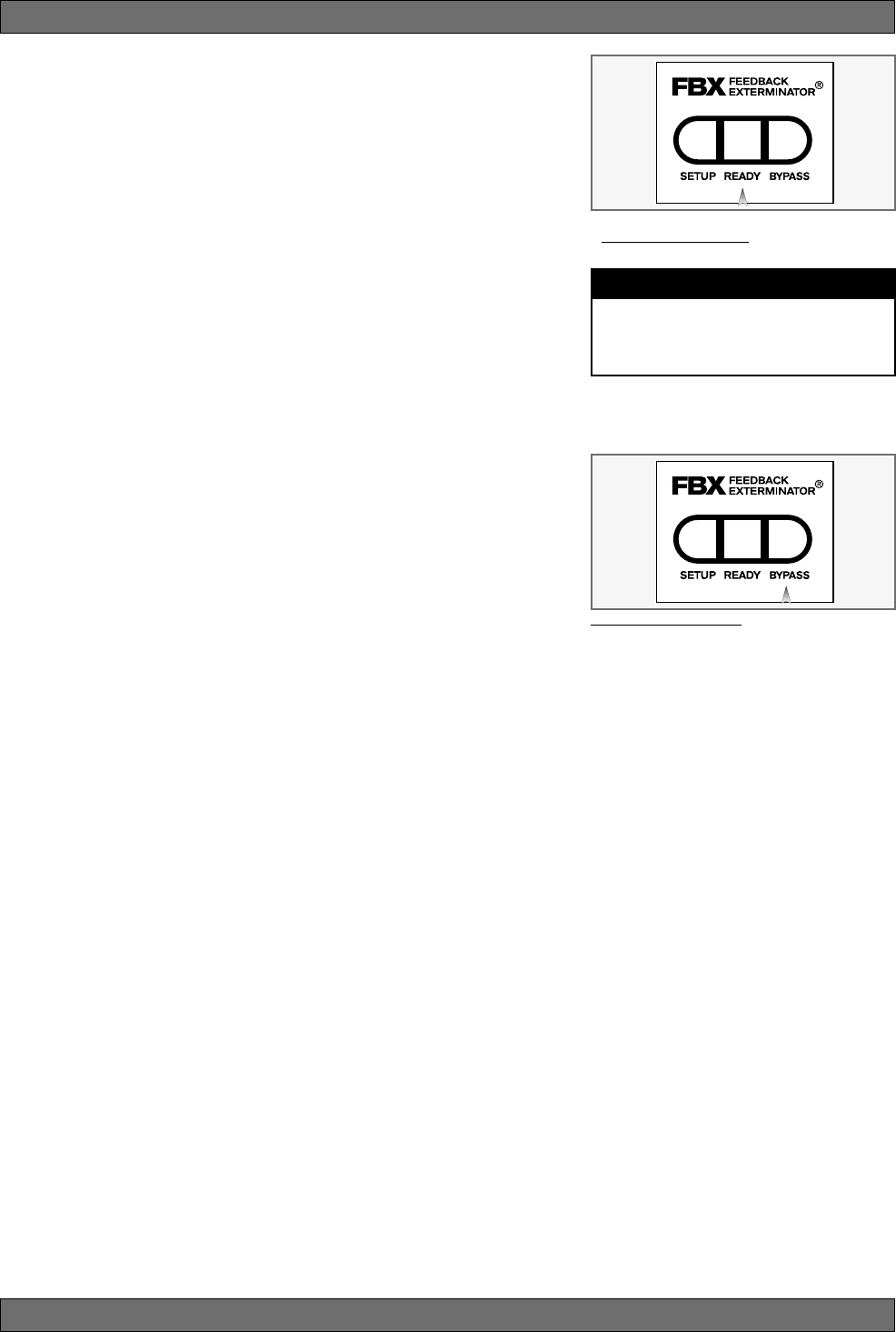
27 Sabine 2.4 GHz Smart Spectrum® Wireless
E-SWM7000-OpGuide-031211.pmd - hto
FBX Feedback Exterminator
Fig. 7c: READY Button
Tech Tip
READY & Locked Fixed
READY = Lock Fixed on other Sabine FBX
products
fully, and your mixer meters show little movement when signal passes through,
then your amplifier will have to work harder to process the weak signal. You
will improve the performance of your sound system and lower system noise
by reducing the gain on your power amp and increasing your mixer gain. FBX
response time will also be better with proper gain structure.
4. First, turn on your receiver and select a clear channel (no RF Signal bars
showing). Then turn on your wireless transmitter or handheld microphone
and select the same channel, Now turn on the mixer (gain low), then any
other accessories, and finally the power amp. If you are using a graphic EQ,
adjust only for the desired tonal qualities, but do not notch for feedback!
5. With the microphone turned on, raise the Output Level of the receiver slowly
until a strong input signal at the mixer is apparent. The microphone should
now be audible.
6. Now you are ready to set FBX filters. Press and hold SETUP (far left button)
on the wireless receiver, until the word SETUP in the channel LCD flashes
4 times, then stops flashing. This will clear any FBX filters already in place.
NOTE: You should do this each time you move your sound system, change
a sound system component, or relocate your microphone. Your Sabine
True Mobility Wireless System will remember its settings from the last time
you turned the unit off.
7. During Setup mode, do not talk into the microphone or pass audio pro-
gram through a transmitter. This may cause the Sabine True Mobility™
system to set inappropriate filters. The only appropriate use of the setup
mode is to create and filter feedback. SETUP must be exited prior to normal
microphone usage. This happens automatically after setting FBX filters, or
you may exit manually by pressing READY at any time.
8. Identify the primary usage positions, and likely feedback-prone locations,
in the potential movement range of the wireless microphone. Take the
microphone to the first of these locations.
Fig. 7d:BYPASS Button
9. Slowly raise the mixer channel gain to the point of feedback — and then slowly beyond, until you hear the chirping tones of
feedback quickly being eliminated by FBX filters setting. Stop raising gain after 2 or 3 feedback tones have chirped and
corresponding FBX filters have set. Rest assured that any feedback that occurs will be at a quiet volume, and very short in
duration.
10. Move the microphone to another area of use and slowly raise gain until FBX eliminates a few more feedback tones (2 or
3). Repeat this step until the word Setup automatically disappears and the word READY appears. This indicates your
unit is ready for operation. The total number of filters available for feedback filtering is 10; in the factory default setting,
your unit will automatically enter READY mode when the eighth filter is set. Alternatively, you may enter READY status with
fewer fixed FBX filters in place, simply by pressing the READY button at any time. NOTE: Be sure that the word READY
appears in the FBX section of your receiver LCD during performance or any normal operation.
Any feedback that occurs after setup will be eliminated by dynamic filters, which remain in reserve to catch surprise
feedback if it occurs during performance/operation.
In most instances you will experience an additional gain of 6-9 dB before feedback when using the Sabine True
MobilityTM System. Precise results will depend on system and acoustical considerations.
All fixed filters in place will remain set until the Setup button is pushed and held as described in step 6. All dynamic filters
will remain in place until new feedback occurs (when they will move to the new frequency), or until the Setup button is
pushed and held. Your True Mobility receiver will remember its FBX (and all other) settings even if the power is turned off.
See Section 14 for a complete discussion of Sabine FBX Feedback Exterminators®.
7.2. FBX Bypass Button
The Bypass button bypasses only the FBX Section, and not the additional signal processing (Parametric Filters, Hi/Lo Cut,
De-essing and Compression) available in the Targeted Input Processing section of the Sabine True Mobility™ Wireless
Receiver.
NOTE: You can easily bypass Compression signal processing by turning the Compressor Ratio knob counterclockwise
until you get to 1:1 ratio, and the De-esser signal processing by turning the De-esser knob clockwise until you get to 0 cut.
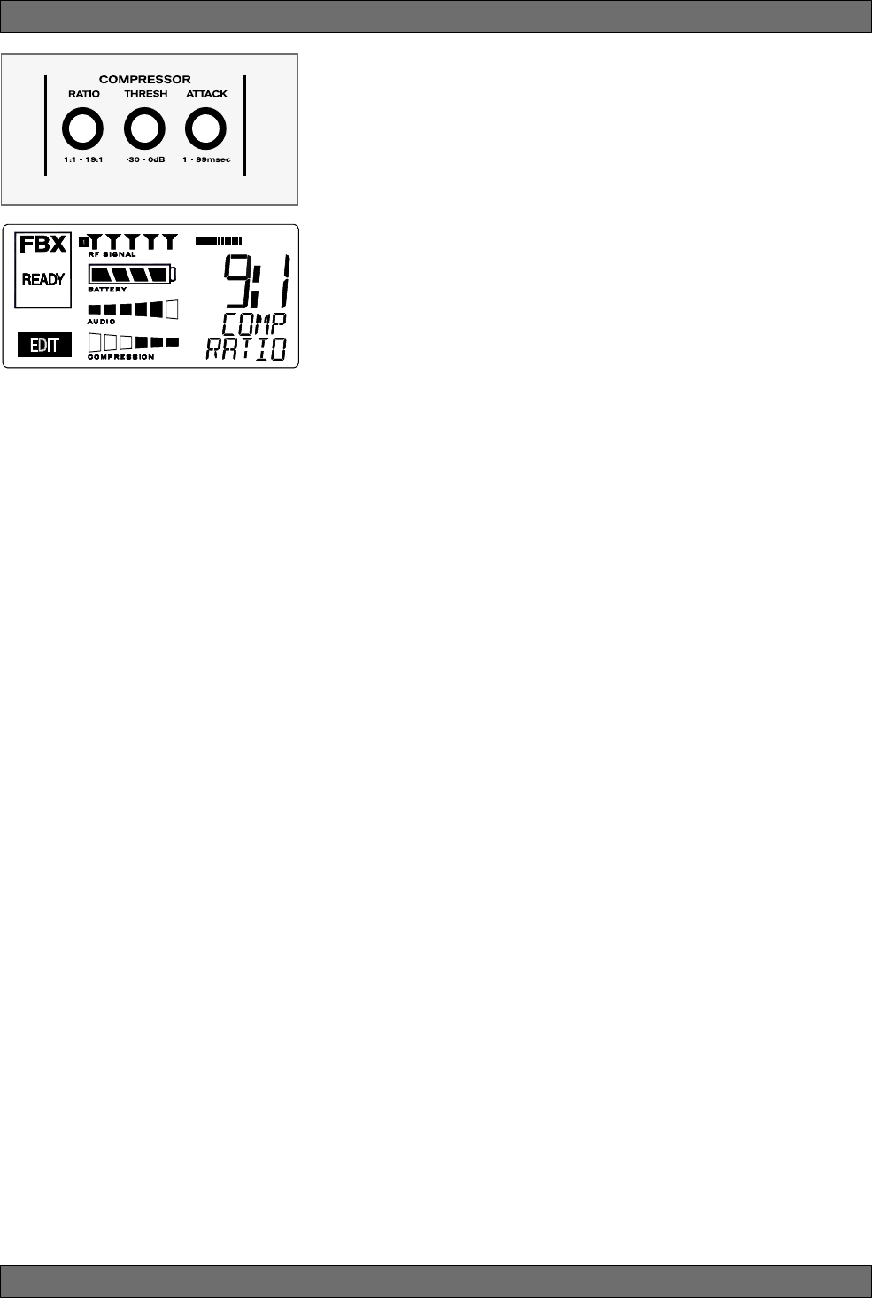
28
Sabine 2.4 GHz Smart Spectrum® Wireless
8. COMPRESSOR/LIMITER OPERATION
8.1. Basics of Compression
The dynamic range (how loud we can hear to how quiet a sound we can detect)
of the human ear is far greater than the capability of sound systems to repro-
duce. Although some of this equipment limitation is at the upper extreme of the
dynamic range (where too loud a signal will produce distortion), much of the
restriction occurs at the low level end, where the signal disappears below the
“noise floor” of the circuitry.
A compressor (or in its most powerful form, a limiter) is the most widely used
tool for controlling dynamic range. In the simplest terms, a compressor is
designed to squeeze the dynamic range of an audio program; i.e., to make
quiet signals louder, and loud signals quieter. A compressor becomes a
limiter when the compression ratio (the ratio of the input gain change to the
output gain change) is so high that the output level effectively won’t rise above
a “brick wall” ceiling, regardless of how much the input gain increases (typi-
cally a ratio of 10:1 and greater).
A compressor acts like an “automatic mix engineer” with a hand on the fader
and an inhumanly fast reaction time. When the input level increases, the
“engineer” drops the fader; when the level decreases, the fader is raised.
When the amount of fader compensation equals the variation in signal level,
the output level of the audio program will sound consistent.
The practical benefits of compression and limiting include:
1. Speaker protection. A compressor will control sudden level peaks and
prevent your speakers from damage. Most often in this type of application,
the compression ratio is high enough to qualify as a limiter.
2. Perceived increase in loudness. Because compressed peak levels are
kept from rising as high as uncompressed signals, you gain headroom for
your audio program and can raise its overall average gain. Compression
is often added to the entire audio mix, both in live sound and recording, to
increase its perceived loudness.
3. Achieving more consistent levels. For expressive instruments or vocals,
which may have a large dynamic range, compression can help maintain
more consistent mix levels. So a speaker who varies from a whisper to a
shout will not disappear or stand out in the mix, relative to other less dy-
namic instruments or vocals. Vocal level variations are also common
when multiple users share a single microphone, due to differences in
voice volumes and mic-to-mouth positions from one user to another. Com-
pression will help even out such variations as well.
8.2. Using the Compressor
Compressor knobs are located immediately to the right of the FBX and De-
Esser controls. The controls consist of standard Ratio, Thresh (threshold) and
Attack knobs, and a horizontal gain ladder in the LED display shows compres-
sor gain reduction.
Ratio: Compression ratio is the ratio of the input gain change to the output
gain change. The compression ratio on your Sabine Wireless ranges
from 1:1 to 19:1, in increments of 1 dB. Set Ratio to 1:1 to bypass
Compressor.
Thresh: Compression threshold sets the input level at which the compressor/
limiter begins to act on the signal. The input level threshold at which
compression is engaged can be adjusted from -30 dBv to 0 dBv, in
increments of 1 dBv.
Attack: Compressor attack time sets the speed with which signal compres-
sion begins once an input signal exceeds the threshold level. The
range may be adjusted from 1 to 99 mS, in 1 mS increments.
Compressor Limiter
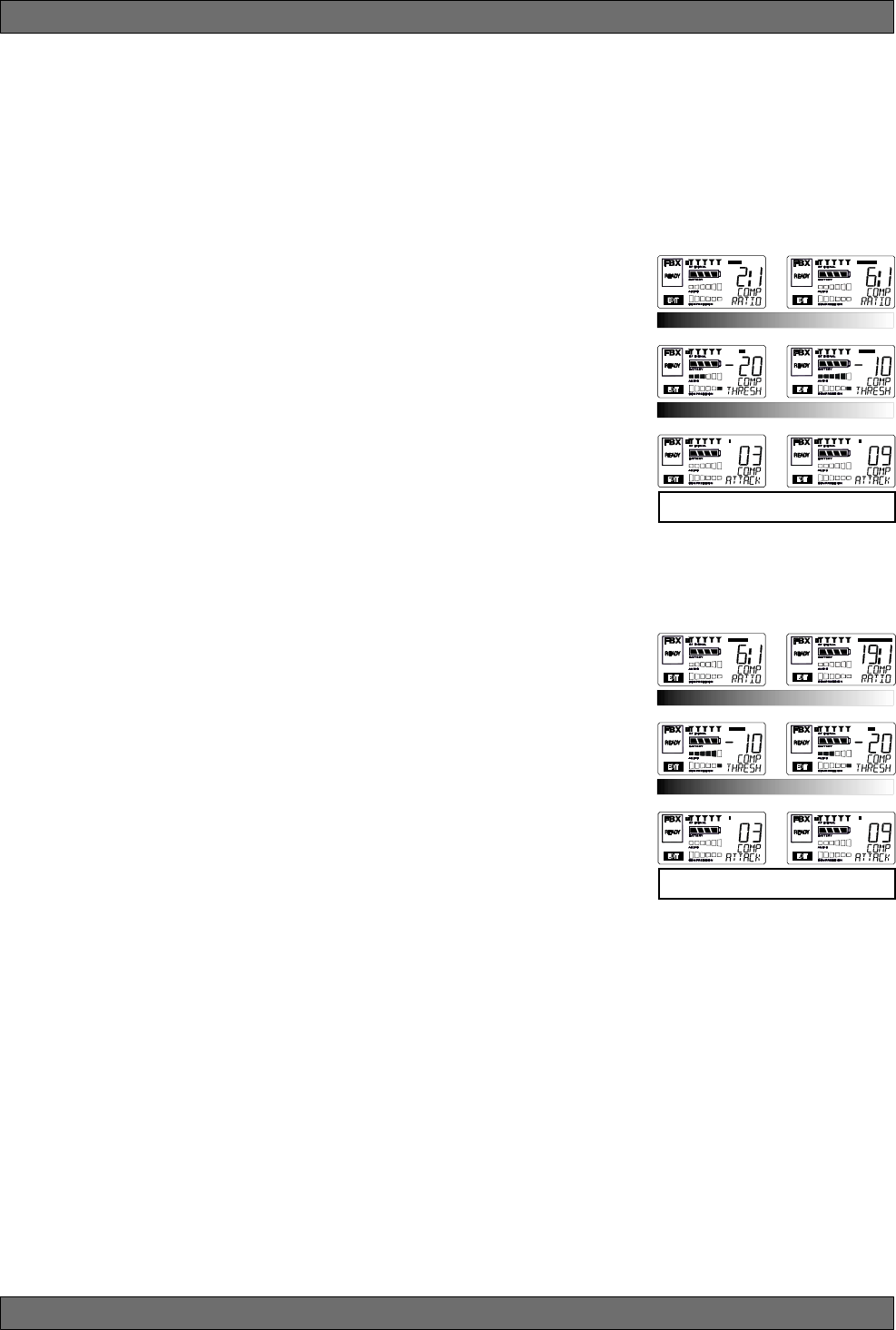
29 Sabine 2.4 GHz Smart Spectrum® Wireless
E-SWM7000-OpGuide-031211.pmd - hto
Compressor Limiter
Gain: (Output Level) Since the output gain is attenuated whenever the input
gain exceeds the compression threshold, the overall output level of a
compressed signal will be reduced. Commonly, this reduced output
gain is compensated for by raising the level of the output signal (the
term is “gain make-up”). Output Level range may be adjusted from
mute (minus infinity) up to +20 dB, in increments of 1 dB (depending
on input).
8.3. Suggested Compression Settings
8.3.1. Vocal Settings
The renowned expressiveness of the human voice is due in large part to its
dynamics. A vocal that varies from a whisper to a scream has a strong
emotional impact, but those same dynamics present a challenge to the
sound engineer. Ideal vocal compression maintains some dynamic range
while keeping the vocal the focal point of the mix.
Ratio: A soft voice might require a ratio of 2:1, whereas a loud voice
might require a ratio setting of 6:1.
Thresh: The higher the threshold setting, the more signal is required to
initiate compression. Ideally this should be set to reign in peak
levels, and allow signals of lower gain to pass uncompressed.
Threshold settings will depend on the nature and variety of the
signal source. Strong vocalists will require a different threshold
than quiet speakers or singers.
Attack: Short attack times usually work well for voice. However, too strong
a compression ratio, too low a threshold, and too fast an attack
may attenuate speech consonants, which provide important in-
telligibility cues to the audience, thus compromising clarity.
8.3.2. Guitar Settings
Ratio: A high compression ratio (with gain makeup) will add sustain to
held notes and chords.
Thresh: Moving the threshold will change the audible thick/thinness of
the guitar tone, but generally you want to compress all the notes
played.
Attack: Be wary of too quick an attack, which may reduce the percussive
attack of the guitar notes.
In general, be wary of too much gain makeup, and too high a compression
ratio, which may make a noisy guitar amplifier more objectionable. Ratio
settings might range from 6 to 20:1, threshold variable, slower attack, soft
knee, output gain boosted slightly to significantly depending on amount of
compression.
8.3.3. Bass Guitar Settings
Bass players use a variety of techniques, often in the same song, that can
benefit from compression. Compressing bass evens out peaks and keeps
the bass level in the mix.
Ratio: Set to 4:1
Thresh: Set to compress peaks only
Attack: Quick attack, medium release, hard knee (try various release
settings, depending on the speed of notes played)
Gain: Output boosted slightly
RATIO
THRESH
ATTACK
RATIO
THRESH
ATTACK
Vocals
Short attack is better for vocals. Be careful not to
over attenuate speech consonants.
Soft voice Loud voice
Soft voice Loud voice
Guitar
Less Sustain More Sustain
Thinner sound Thicker sound
Be wary of too quick an attack, which may reduce the
percussive attack of the guitar notes.