SALUS North America AKL06PRF Zigbee Pump Wiring Centre User Manual
SALUS North America, Inc. Zigbee Pump Wiring Centre
User manual

AKL04PRF Zone Pump Wiring Center
Wiring Guide
AUX XX ZONE1 E/S
TRANSFORMER
L N
GROUND
L N
PUMP2
L N
PUMP3
L N
PUMP4
L N
PRIMARY
PUMP
L N
120 VAC
OUTPUT
MASTER
PRIORITY ON
EXERCISE ON
PRIMARY STATUS DURING PRIORITY ON
PURGE ON
SLAVE
OFF
OFF
OFF
OFF
Group 1 thermostats
G1 (1-2)
120 VAC
120VAC TO PUMP Cables will
be supplied by the installer.
H N
H N
R W C
C1 C2
COMMS
BOILER
FUSE 5A
SLOW BLOW
FUSE 5A
SLOW BLOW
FUSE 5A
SLOW BLOW
FUSE 5A
SLOW BLOW
FUSE 5A
SLOW BLOW
POWER IN GROUND PRIORITY
PUMP1
Group 2 thermostats
G2 (3-4)
ZC N
GND
24V-T-STAT 1
R CW
Domestic Hot Water/Zone
24VAC thermostat
Group 1 thermostats
G1 (1-2)
Group 2 thermostats
G2 (3-4)
120VAC TO PUMP
(Cables to be supplied by installer)
WIRED WIRELESS
External Antenna
INT EXT
Antenna Selection
24VAC Thermostat Connections
R / H 24VAC
W / Call for Heat
C / N 24VAC common
Dry Contacts (rated 120VAC, max.2A)
AUX Auxiliary
XX Active Pump(s)
Zone1 E/S Local Priority
Master/Slave Communication Lines (5V)
C1 Master Priority
C2 Slave Active
GND Communication Ground
120VAC Connections
LAC Line In (max. 20A)
Zone Pump Line Out (max. 1/6 HP)
N AC Neutral
ZC Zone control/Priority Input(120VAC)
Earth Ground
Fuse: 5A slow blow, 5x15mm (2AG)
BOILER
Electrical Connections
FCC/IC Statements and Notices
Changes or modifications not expressly approved by the party responsible for compliance could void the user’s
authority to operate the equipment. This device complies with part 15 of the FCC Rules. Operation is subject
to the following two conditions: (1) This device may not cause harmful interference, and (2) this device must
accept any interference received, including interference that may cause undesired operation. This equipment
has been tested and found to comply with the limits for a Class B digital device, pursuant to Part 15 of the FCC
Rules. These limits are designed to provide reasonable protection against harmful interference in a residential
installation. This equipment generates uses and can radiate radio frequency energy and, if not installed and used
in accordance with the instructions, may cause harmful interference to radio communications. However, there
is no guarantee that interference will not occur in a particular installation. If this equipment does cause harmful
interference to radio or television reception, which can be determined by turning the equipment off and on, the
user is encouraged to try to correct the interference by one or more of the following measures:
• Reorient or relocate the receiving antenna.
• Increase the separation between the equipment and receiver.
• Connect the equipment into an outlet on a circuit different from that to which the receiver is connected.
• Consult the dealer or an experienced radio/TV technician for help.
FCC and Industry Canada
RF Radiation Exposure statement: This equipment complies with FCC and Industry Canada RF radiation exposure
limits set forth for an uncontrolled environment. This equipment should be installed and operated with a
minimum distance of 20 centimeters between the antenna and all persons.
Cet appareil est conforme aux limites d’exposition au rayonnement FR du FCC et d’Industrie Canada pour un
environnement non contrôlé. Cet appareil devrait être installé et devrait fonctionner de sorte qu’il se trouve à
une distance d’au moins 20 cm entre l’antenne et toute personne.
Industry Canada
This device complies with Industry Canada licence-exempt RSS standard(s). Operation is subject to the following
two conditions: (1) this device may not cause interference, and (2) this device must accept any interference,
including interference that may cause undesired operation of the device.
Le présent appareil est conforme aux CNR d’Industrie Canada applicables aux appareils radio exempts de licence.
L’exploitation est autorisée aux deux conditions suivantes : 1) l’appareil ne doit pas produire de brouillage, et (2)
l’utilisateur de l’appareil doit accepter tout brouillage radioélectrique subi, même si le brouillage est susceptible
d’en compromettre le fonctionnement.
Issue Date: Apr 2017
For PDF Installation guide go to
www.salusinc.com Technical Helpline 1-855-557-2587
Warning
This product must be installed by qualified
personnel and the installation must comply
with the codes and regulations applicable to
the municipality where this product is installed.
Failure to do so could lead to injury, death, or
prosecution.
Always disconnect the AC power before
installing or working on AC power components.
AUX XX ZONE1 E/S
TRANSFORMER
L N
GROUND
L N
PUMP2
L N
PUMP3
L N
PUMP4
L N
PUMP5
L N
PUMP6
L N
PRIMARY
PUMP
L N
120 VAC
OUTPUT
24V - T-STAT 1
120 VAC
120VAC TO PUMP Cables will
be supplied by the installer.
H N
H N
R W C
C1 C2
COMMS
BOILER
FUSE 5A
SLOW BLOW
FUSE 5A
SLOW BLOW
FUSE 5A
SLOW BLOW
FUSE 5A
SLOW BLOW
FUSE 5A
SLOW BLOW
FUSE 5A
SLOW BLOW
FUSE 5A
SLOW BLOW
POWER IN GROUND PRIORITY
PUMP1
ZC/ZR
Group 1 thermostats
G1 (1-2)
Group 2 thermostats
G2 (3-6)
AHTR5024 AHTR3024 AHTR3024 AHTR3024 AHTR3024 AHTR3024
MASTER
PRIORITY ON
EXERCISE ON
PRIMARY STATUS DURING PRIORITY ON
PURGE ON
SLAVE
OFF
OFF
OFF
OFF
Wired Wireless
Antenna Selection
INT EXT
POWER PRIORITY
ZONE 1
ZONE 2
ZONE 3
ZONE 4
ZONE 6
G1
G2
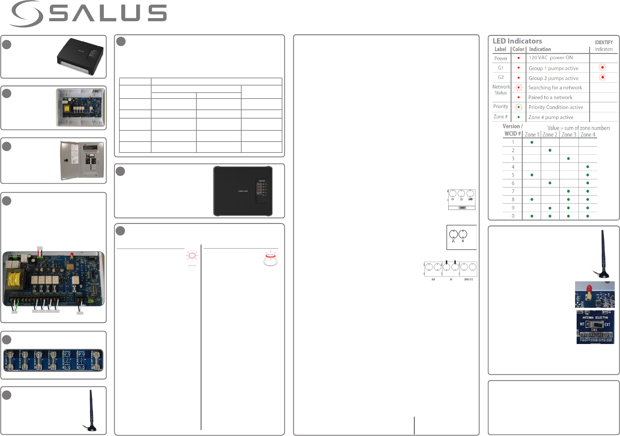
Network Status
•
•
1Remove the
plastic cover by
unscrewing the
4 screws at the
corners.
2 Attach the back
of the device to
the wall at a
suitable location
using the included
hardware.
Make sure that the fuses are each of 5 Amp,
slow blow and in the correct position.
5
AKL04PRF Zone Pump Wiring Center
Installation Guide
4Wire the device to the AC power supply
and zone pumps using wiring appropriate
for 120VAC. Connect other terminals as
appropriate to other devices using proper
wiring. Be sure to thread wiring through
the knock outs and use cable clamps to
fasten the wiring to the device.
3Disconnect the
AC power to the
AC wiring for the
device.
If you know you will need
an external antenna, please
follow the instructions to the
right for External Antenna
Installation.
6
7Use the table below to configure the switches on the device. For
descriptions of the functions, see the Operational Summary to the right.
These switches are only read at power up. If you are using a wired
thermostat, need Priority Zone functionality and/or have a Primary pump
or external antenna, set the switches appropriately now. Any changes will
require AC power to be removed from the device, then restored.
8Re-attach the plastic cover, securing
it with the 4 screws and switch on
the AC power to the unit.
The Power LED will come on and the
Network Status LED will flash red.
The device is now ready to connect to the network. Follow the steps for
the selected type of network to add the device to the network.
Local Only Network using ZigBee Coordinator
1. Plug the Coordinator into a centrally
located outlet in the home if you
have not already done so.
2. Press and hold the button on the
Coordinator until the button flashes red (about
five seconds).
• The Coordinator is now ready to pair and is
looking for devices.
• The Network Status LED on each wiring center
will go steady red when connected to the
Coordinator. One Coordinator can support up to
nine wiring centers.
3. Determine the network ID number for a wiring
center by pressing the Pair button briefly and
adding the numbers associated with the lit
Zone LEDs (see Version / ID# chart under LED
Indicators).
4. Pair and setup the Salus thermostats according
to the thermostat manual, using the wiring
center ID number determined in the previous
step.
5. When all thermostats are setup, press and hold
the button on the Coordinator until the button
is steady red (about five seconds).
Checking System Configuration and Communication
Coordinator to Wiring Centers
Press and hold the coordinator button for one second.
All devices connected to the coordinator will flash. To
stop checking, press and hold the coordinator button
again for one second.
9
Internet Connected Network using Basic Gateway
1. Setup the Basic Gateway as
instructed and associate the
gateway with the wyse.ly
service account.
2. Go to the Add New Equipment page
on the wyse.ly App and press “Scan for
equipment”.
• The gateway ring will flash red indicating
that it is looking for devices.
3. Use the wyse.ly app to add the wiring
centers to your wyse.ly network.
• The Network Status LED on each wiring
center will go steady red when connected to
the Basic Gateway.
4. Use the wyse.ly app to add the Salus
thermostats to your network and associate
them with the desired wiring center and
zone.
5. When all devices are setup, exit the Add
New Equipment function on the wyse.
ly App.
• The gateway ring will turn steady blue to
indicate normal operating mode.
Checking System Configuration and Communication
Gateway to Wiring Centers
Go to the Wyse.ly App and press the Identify button
for the desired wiring center. The desired wiring
center will start flashing the G1 and G2 LEDs. To
stop the identify process, press the Identify button
on the App again.
Operational Summary
Following is a brief summary of the functions available in the AKL04PRF wiring center
to simply and safely connect thermostats and corresponding pumps.
Group Function (available only in Local Only Network)
The wiring center can have four different configurations:
•One standalone thermostat for each zone (4 thermostats in total)
•Two groups: Group 1 (G1), zones 1-2, with a master thermostat and optional
slave thermostat, and Group 2 (G2), zones 3-4, with a master thermostat and
one slave thermostat
•Group 1 with master/slave thermostats and the other zones (3-4) with standalone
thermostats
•Zones 1 and 2 with standalone thermostats and Group 2 with master/slave
thermostats
For wireless thermostats, groups are set on the thermostat during the pairing process.
When "gr” flashes on the thermostat display, press UP/DOWN arrows to select the
group number. Group “_ _” is standalone operation.
Zone Pumps
The Zone Pumps are activated when the associated thermostats call for heat, except
when a Priority Zone call is Active, in which case the pumps are turned off.
Exercise Function
When turned on, the Exercise function will turn ON a pump for 30 seconds after 72
hours of no activity on that pump.
Master/Slave Connections
The three terminals (C1, C2, and GND) can be used to connect up to
4 other wiring centers (5 total). They are wired in parallel (C1 to C1 to
C1, C2 to C2 to C2, etc.) with up to 100 meters from end to end. Only
one wiring center can be the Master, the other wiring centers must be
Slaves, as determined by the position of the MASTER / SLAVE DIP switch.
ZC/N Connector (Master wiring center only)
A Master wiring center without Priority uses the ZC/N terminals to
enable or disable the wiring center, typically from the boiler ZR/ZC
120 VAC contacts. When 120 VAC is applied across the ZC/N terminals,
the wiring center is enabled. When 120 VAC is not applied, the wiring
center is disabled and all pumps are switched OFF.
Dry Contacts (Master wiring center only)
There are three sets of dry contacts in the wiring center.
AUX: Contact closure when any pump is ON and Priority Zone is not active.
XX: Contact closure when any pump is ON, including an active Priority Zone.
Zone1 E/S: Contact closure when Priority Zone is active. Can be used for self regulated pumps or other controls.
Priority Zone Function (Master wiring center only)
The Priority Zone function is usually used to give domestic hot water (DHW) priority for
the boiler output. Activating this function will change the behavior of Zone 1 on the
MASTER wiring center. When Priority is ON and the Zone 1 thermostat calls for heat,
the following occurs as part of an active Priority Zone:
•Zone 1 pump is turned ON and all other pumps, including those on SLAVE wiring
centers, are turned OFF.
•The Zone 1 pump runs for 1 hour, after which all zones resume their normal
operation.
•The Priority Zone function can be canceled early by having the Zone 1 thermostat
end the call for heat.
•Another Priority Zone call after the 1 hour period cannot be initiated until the
Zone 1 thermostat ends the initial call for heat.
Purge Function (Master wiring center only)
When turned on, the Purge function will keep the Zone 1 pump ON for 2 minutes
following the end of a Priority Zone call. All other zones will remain off during
the purge.
Primary Pump Function (Master wiring center only)
The Primary Pump controls the heating system and it switches ON when any zone is ON,
including zones on SLAVE wiring centers, except:
PRIORITY switch is ON,
PRIMARY STATUS DURING PRIORITY switch is OFF,
and Priority Zone is Active,
WHEN: THEN: Primary Pump is OFF
External Antenna Installation
If you need to install an external antenna,
perform the following:
•Disconnect power
•Remove the protective cover from
the External Antenna connector on
the top edge of the board.
•Pass the antenna cable
through the antenna knock
out (and cable clamp) on the
top of the housing and screw
the cable onto the connector.
•Secure the cable using a cable
clamp.
•Change the Antenna Selection
switch from INT to EXT.
•Reconnect power
Factory Default Reset
To restore the device to Factory Default settings, press and
hold the Pair button until both G1 and G2 LEDs go off after
becoming steady red.
Note: Restoring to Factory Default will remove the wiring
center from the network and delete all associated devices.
Definition
DIP Switch
Master
ON OFF
Slave
MASTER/SLAVE
PRIORITY
EXERCISE
PRIMARY STATUS
DURING PRIORITY
PURGE
WIRED/WIRELESS
Zone1 is Priority Zone
Exercise ON for all pumps
Primary Pump ON during
Priority
Zone1 OFF 2 min after end
of Priority
Wired thermostat for Zone1
Zone1 is Pump Zone
Exercise OFF for all pumps
Primary Pump OFF during
Priority
Zone1 OFF at the end of
Priority
Wireless thermostat for
Zone1
IGNORED:
Zone1 is pump zone
Same as Master
IGNORED: Primary
Pump always OFF
IGNORED:
No Priority
Same as Master
The device will now use the external antenna for wireless
communication.
Note: For regulatory compliance, only the Salus A8RFA
antenna (sold separately) can be used with this device.