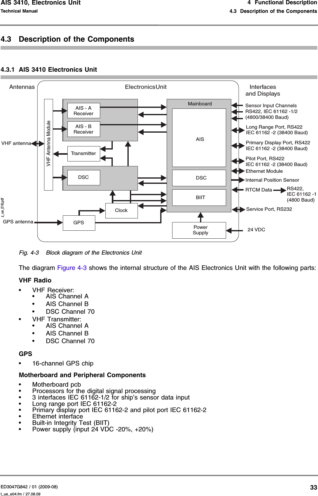
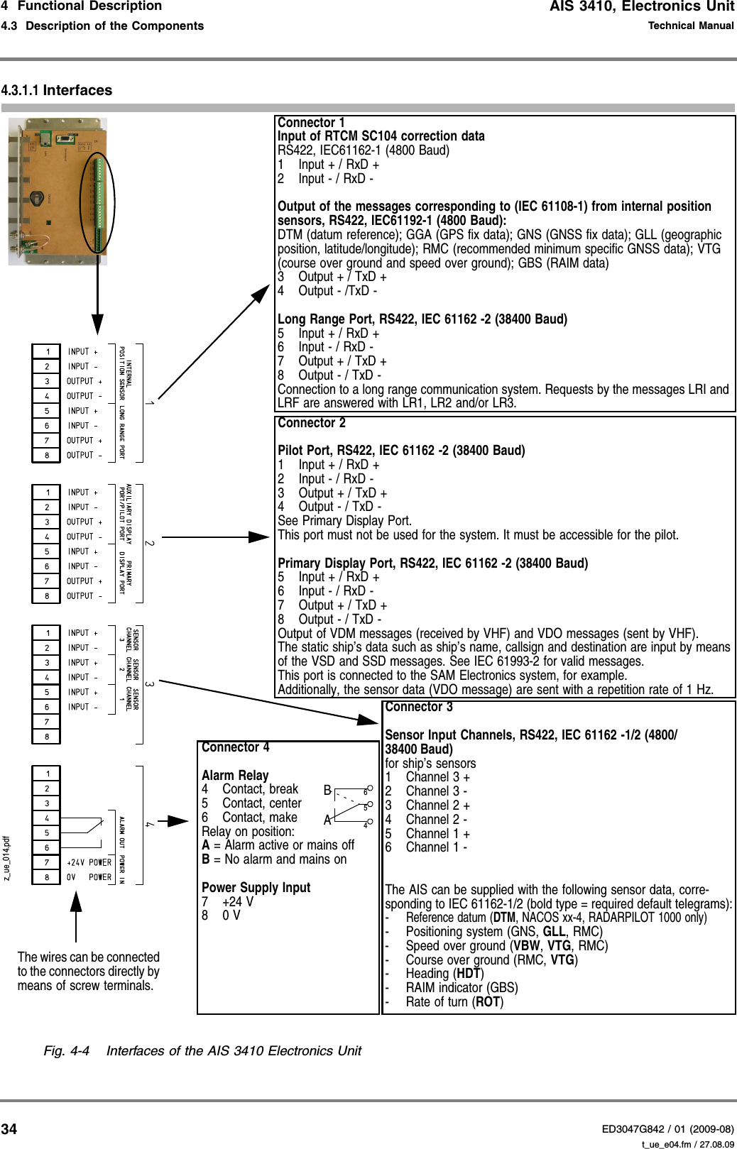
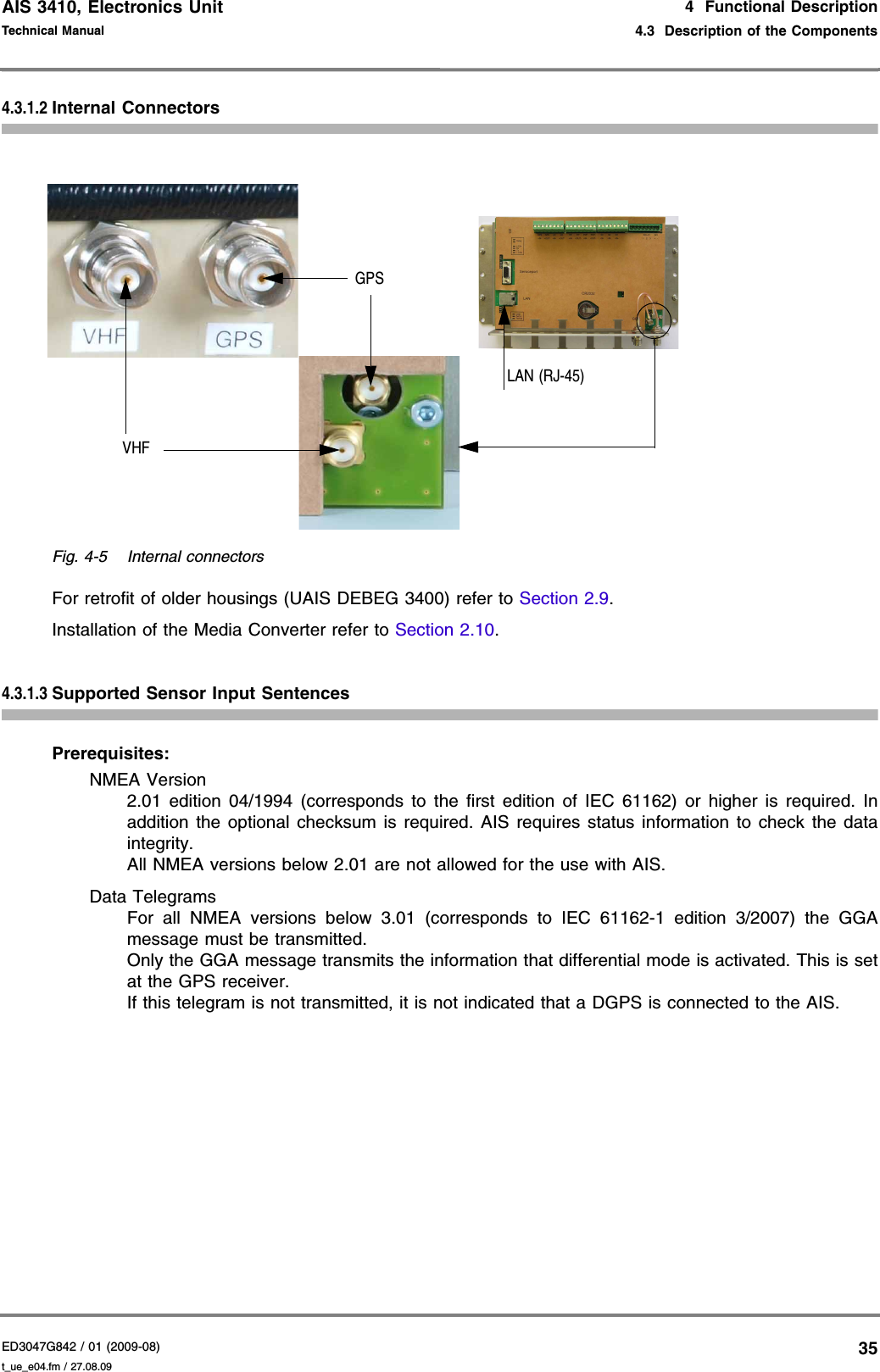
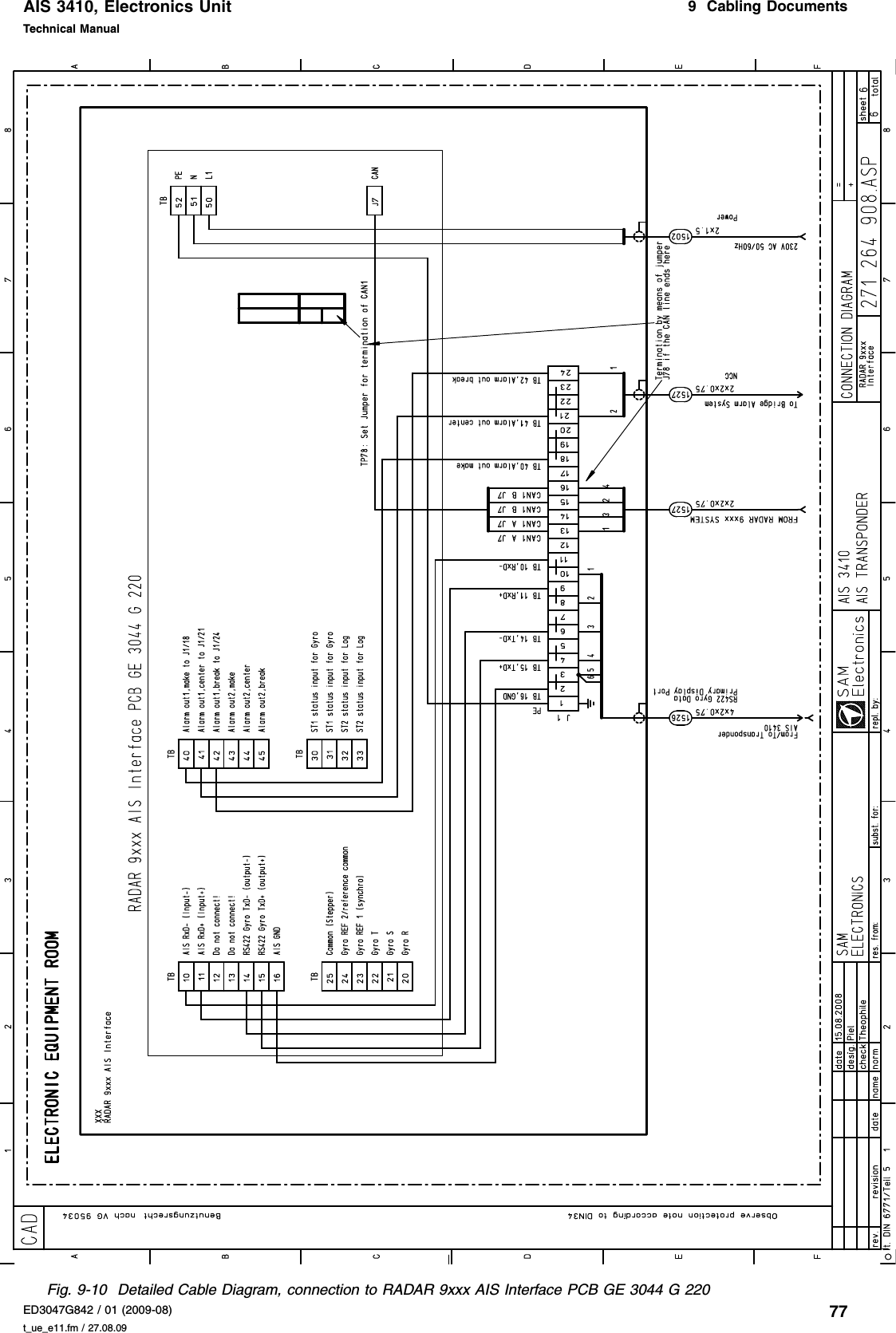
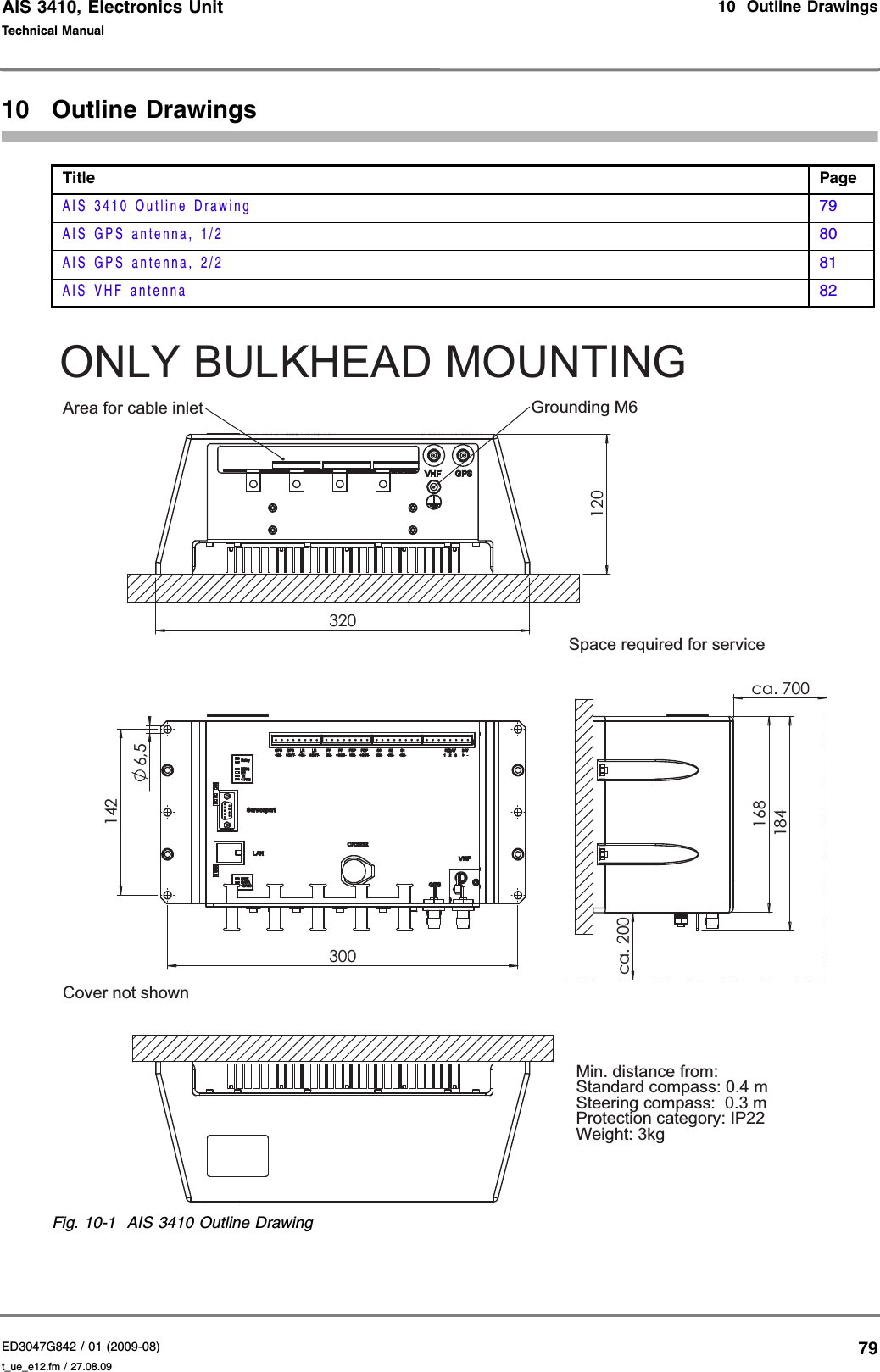
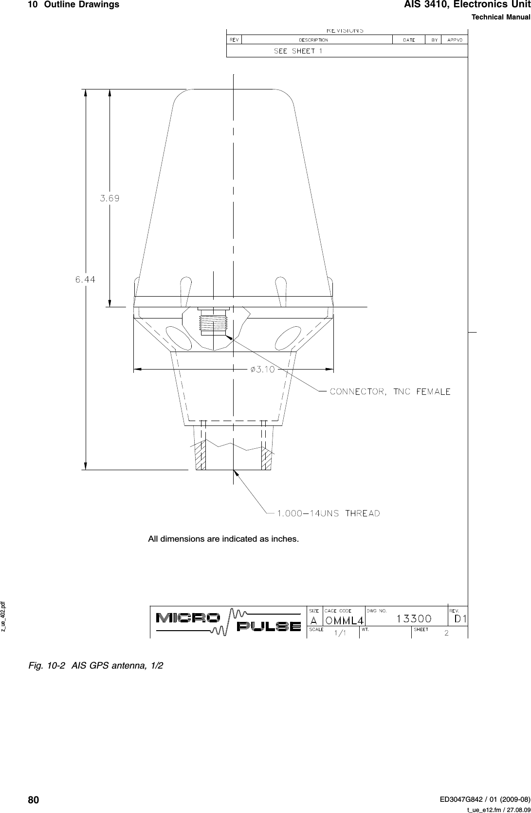
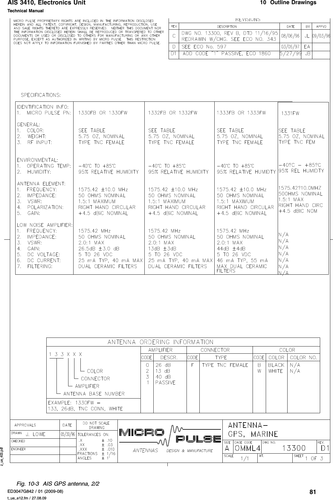
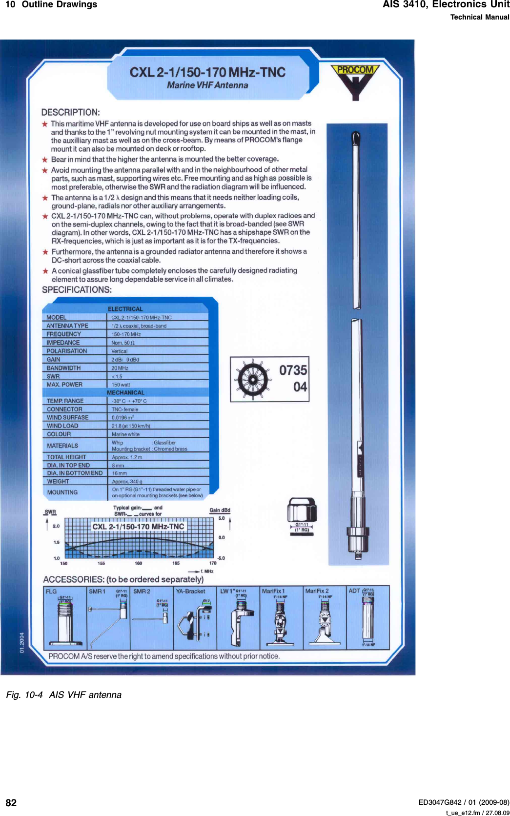
SAM Electronics AIS3410 Maritime AIS Transponder User Manual t ue e
SAM Electronics GmbH Maritime AIS Transponder t ue e
UserManual.wiki
>
SAM Electronics
>
AIS3410 User Manual
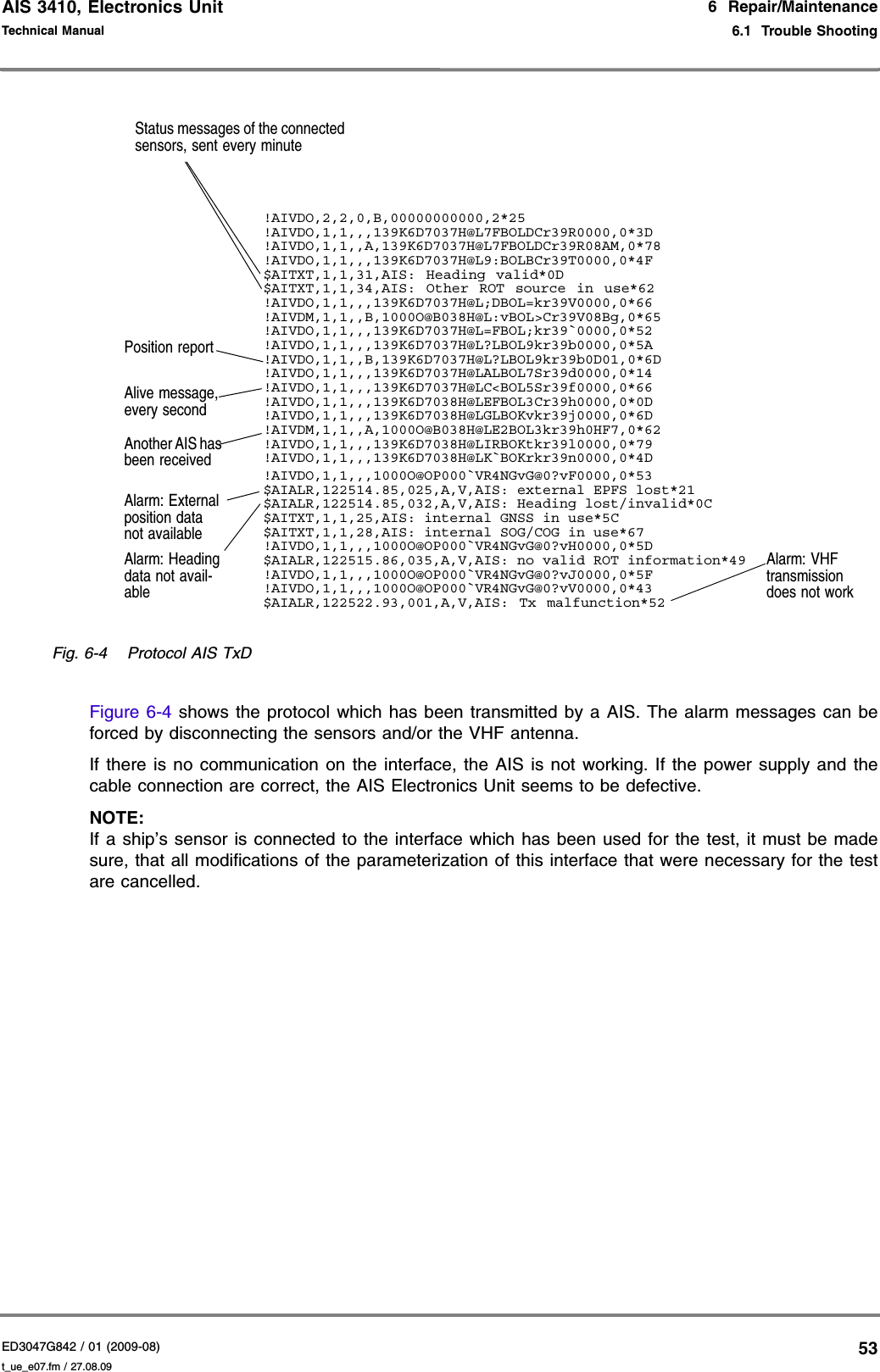
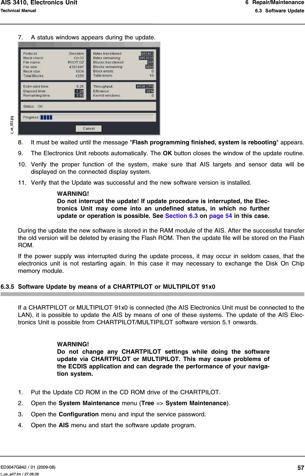
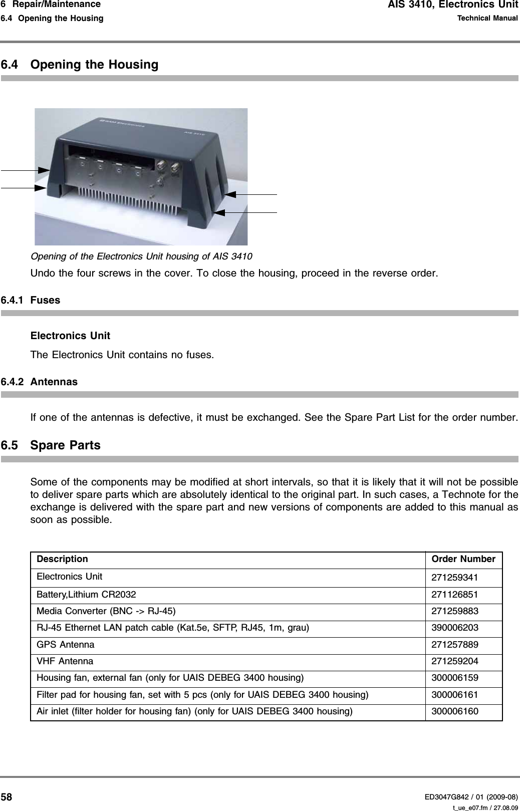
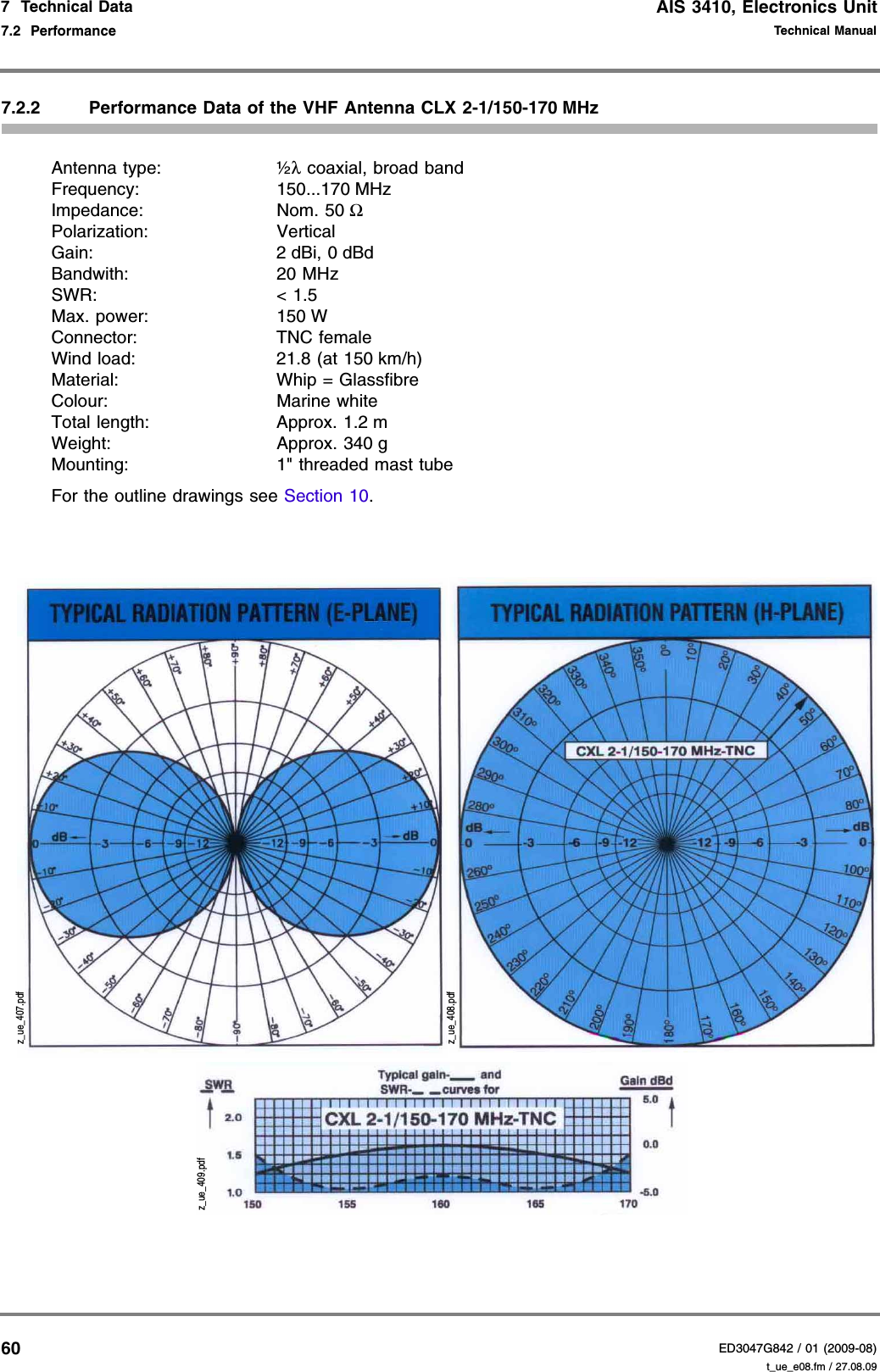
Users Manual
Navigation menu
Upload a User Manual
Namespaces
Wiki Guide
HTML
PDF
Info
Views
User Manual
Discussion / Help
Navigation