SAM Electronics AIS3410 Maritime AIS Transponder User Manual t ue e
SAM Electronics GmbH Maritime AIS Transponder t ue e
Users Manual

Technical Manual
Automatic Identification System
AIS 3410
Electronics Unit
Item No.: ED3047G842 Revision: 01 (2009-08) Order No.: 390007907

t_ue_eti.fm / 27.08.09
© SAM Electronics GmbH 2009
This document is our property for which we reserve all rights, including
those relating to patents or registered designs. It must not be
reproduced or used otherwise or made available to any third party without
our prior permission in writing.
Alterations due to technical progress are reserved.
SAM Electronics GmbH
D - 22763 Hamburg
Service
Customer Support Center
Phone: + 49 (0) 18 03 00 85 53
Fax: + 49 (0) 18 03 00 85 54
E-mail: shipservice@sam-electronics.de

AIS 3410, Electronics Unit
ED3047G842 / 01 (2009-08)
Technical Manual List of Contents
t_ue_eIV.fm / 27.08.09
3
List of Contents
List of Contents 3
List of Figures 5
List of Abbreviations 7
1 General 9
1.1 Software Releases 9
1.2 General Recommendations for Installation, Maintenance and Repair Work 9
1.3 Safety Warnings 9
2Overview 11
2.1 Compatibility with Other Systems 11
2.2 AIS 3410 in RADARPILOT 1000/1100 Systems 12
2.3 AIS 3410 in 1000/1100 Series Systems (NACOS xx-4 and xx-5) 13
2.4 AIS 3410 in CHARTPILOT Stand-alone Systems 14
2.5 AIS 3410 in NACOS xx-3 Systems (Radar 9xxx and CHARTPILOT) 15
2.6 AIS 3410 in Radar 9xxx Systems with RADARPILOT 1000/1100 16
2.7 AIS 3410 in Radar 9xxx Systems 17
2.8 Housing of the 3410 Electronics Unit 18
2.9 Replacement of AIS Electronics Unit 19
2.9.1 Open the Housing of AIS 3410 19
2.9.2 Open the Housing of UAIS DEBEG 3400 19
2.9.3 Merge the AIS 3410 Electronics Unit into the UAIS DEBEG 3400 Housing 20
2.10 Media Converter Installation (necessary for ships with BNC LAN networks) 20
3 Installation Recommendations 21
3.1 General Recommendations 21
3.1.1 Cables 21
3.1.1.1 Maximum Cable Length 22
3.1.1.2 Cable Sets 23
3.1.2 Electronics Units 23
3.2 Specific Recommendations 24
3.2.1 Recommendations Concerning AIS Systems 24
3.2.2 Recommendations Concerning the Installation of the Electronics Unit 25
3.2.3 Recommendations Concerning the Installation of the Antennas 25
3.2.3.1 Recommendations Concerning the Installation of the VHF Antenna 26
3.2.3.2 Recommendations Concerning the Installation of the GPS Antenna 27
3.2.4 Recommendations Concerning Redundancy 28
3.2.5 Recommendations Concerning the Connection of a (D)GPS to AIS 3410 28
3.2.6 Emergency Power Source 28
3.2.7 Pilot Port, Connector/Cable Kits 28
3.2.8 Recommendations Concerning AIS Stand-alone with Radar 9xxx / NACOS xx-2/-3 29
3.2.9 Recommendations Concerning the Connection to a Radar 1000/1100 Series System 29
3.2.10 Recommendations Concerning the Connection to a Radar 1100 Series System 29
4 Functional Description 31
4.1 Block Diagram 31
4.2 Termination 32
4.3 Description of the Components 33
4.3.1 AIS 3410 Electronics Unit 33
4.3.1.1 Interfaces 34
4.3.1.2 Internal Connectors 35
4.3.1.3 Supported Sensor Input Sentences 35
4.3.1.4 Supported Sentences for the AIS Primary Display Port and the Pilot Port 37
4.3.1.5 Supported Sentences for the Long Range Port 38
4.3.1.6 Supported Sentences for the Internal Position Sensor 40
4.3.1.7 IEC 61162 -1/-2 Interfaces, Electrical Characteristics 41
4.3.1.8 Example for the Interconnection 42
4.3.2 VHF Antenna 42

AIS 3410, Electronics Unit
ED3047G842 / 01 (2009-08)
Technical Manual
List of Contents
t_ue_eIV.fm / 27.08.09
4
4.3.3 GPS Antenna 43
4.3.4 Pilot Port 43
5 Setting-to-Work/Configuration 45
5.1 Setting-to-Work 45
5.2 Software Versions 45
5.3 Configuration 45
5.3.1 Configuration with RADARPILOT/CHARTRADAR/MULTIPILOT 1000/1100 - NACOS xx-4/5 Systems 45
5.3.2 Configuration with CHARTPILOT 93xx in NACOS xx-3 Systems 46
5.3.3 Configuration with Radar 9xxx 46
5.4 Testing 46
5.5 LEDs for Ethernet LAN, Alarm, GPS and Telegram 46
6 Repair/Maintenance 47
6.1 Trouble Shooting 47
6.1.1 Hints 47
6.1.2 Fault Tree 48
6.1.3 Trouble Shooting for AIS 3410 connected to a RADARPILOT 1000/1100 49
6.1.3.1 Indication: System Fault Message 3617 Displayed on Indicator 49
6.1.3.2 Indication: System Fault Message 3616 Displayed on Indicator 54
6.2 Test of the Antenna Performance 54
6.3 Software Update 54
6.3.1 Software download from SAM-CMIS 54
6.3.2 Determination of the Current Software Versions 55
6.3.3 Serial Cable Connection 55
6.3.4 Software Update by means of a Laptop 56
6.3.5 Software Update by means of a CHARTPILOT or MULTIPILOT 91x0 57
6.4 Opening the Housing 58
6.4.1 Fuses 58
6.4.2 Antennas 58
6.5 Spare Parts 58
7 Technical Data 59
7.1 Conformity to Standards, Environmental Conditions 59
7.2 Performance 59
7.2.1 Performance Data of the Electronics Unit 59
7.2.2 Performance Data of the VHF Antenna CLX 2-1/150-170 MHz 60
7.2.3 Performance Data of the GPS Antenna 61
7.3 Dimensions and Weights 61
7.4 Compass Safe Distances 61
8 Fault Code List 63
9 Cabling Documents 67
10 Outline Drawings 79
Notes 83

AIS 3410, Electronics Unit
ED3047G842 / 01 (2009-08)
Technical Manual List of Figures
t_ue_eAV.fm / 27.08.09
5
List of Figures
Fig. 2-1 AIS 3410 in RADARPILOT 1000/1100 systems 12
Fig. 2-2 AIS 3410, SAM Electronics 1000/1100 series systems (NACOS xx-4/NACOS xx-5) 13
Fig. 2-3 AIS 3410 with CHARTPILOT stand-alone 14
Fig. 2-4 AIS 3410 in NACOS xx-3 systems 15
Fig. 2-5 AIS 3410 in Radar 9xxx systems with RADARPILOT 1000/1100 16
Fig. 2-6 AIS 3410 in Radar 9xxx systems 17
Fig. 2-7 AIS 3410 Electronics Unit (current version) 18
Fig. 2-8 UAIS DEBEG 3400 Electronics Unit (old versions) 18
Fig. 2-9 AIS 3410 Electronics Unit (without housing) 20
Fig. 3-1 Cable inlet consisting of a hole with brackets 22
Fig. 3-2 Minimum distances for GPS and VHF Antenna 25
Fig. 3-3 Positioning of the VHF Antenna 26
Fig. 3-4 Positioning of the GPS Antenna 27
Fig. 3-5 Minimum distances for the GPS Antenna from a Radar Scanner 27
Fig. 4-1 Block diagram of the AIS System 31
Fig. 4-2 Principle of wiring for Ethernet LAN 32
Fig. 4-3 Block diagram of the Electronics Unit 33
Fig. 4-4 Interfaces of the AIS 3410 Electronics Unit 34
Fig. 4-5 Internal connectors 35
Fig. 4-6 AIS and Gyro Interface 9401 42
Fig. 4-7 Pilot Port, connector assignment, front view (pins) 43
Fig. 5-1 Status LEDs 46
Fig. 6-1 Cable connection for the interface monitoring Radar > AIS 50
Fig. 6-2 Protocol Radar TxD 51
Fig. 6-3 Cable connection for the interface monitoring AIS > Radar 52
Fig. 6-4 Protocol AIS TxD 53
Fig. 6-6 Service Interface 56
Fig. 9-1 Cable Diagram, connection to RADARPILOT 1x00, NACOS xx-4/5 via ... 68
Fig. 9-2 Cable Diagram, connection to CHARTPILOT, NACOS xx-4/5, RADAR /... 69
Fig. 9-3 Cable Diagram, connection to CHARTPILOT stand-alone 70
Fig. 9-4 Cable Diagram, connection to Radar 9xxx via Radar 9xxx AIS Interface (NACOS xx-3) 71
Fig. 9-5 Detailed Cable Diagram, connection to RADARPILOT 1x00, NACOS xx-4/5 via ... 72
Fig. 9-6 Detailed Cable Diagram, Wheelhouse Console 73
Fig. 9-7 Detailed Cable Diagram, connection to NACOS xx-4/5, RADAR / ... 74
Fig. 9-8 Detailed Cable Diagram, connection to CHARTPILOT stand-alone systems 75
Fig. 9-9 Detailed Cable Diagram, connection to RADAR 9xxx AIS Interface 76
Fig. 9-10 Detailed Cable Diagram, connection to RADAR 9xxx AIS Interface PCB GE 3044 G 220 77
Fig. 10-1 AIS 3410 Outline Drawing 79
Fig. 10-2 AIS GPS antenna, 1/2 80
Fig. 10-3 AIS GPS antenna, 2/2 81
Fig. 10-4 AIS VHF antenna 82

AIS 3410, Electronics Unit
ED3047G842 / 01 (2009-08)
Technical Manual
List of Figures
t_ue_eAV.fm / 27.08.09
6

AIS 3410, Electronics Unit
ED3047G842 / 01 (2009-08)
Technical Manual
List of Abbreviations
t_ue_eak.fm / 27.08.09
7
List of Abbreviations
This list also contains abbreviations which are not used in this manual but in additional documentation.
A
AIS Automatic Identification System
B
BIIT Built-In Integrity Test
C
COG Course Over Ground
D
DSC Digital Selective Call
E
ECDIS Electronic Chart Display and Information System
H
HDG Heading
L
LR Long Range
M
MAC Medium Access Control
MKD Minimum Keyboard and Display
MMSI Maritime Mobile Service Identity
P
PDP Primary Display Port (Presentation Interface)
PP Pilot Port (Auxiliary Display Port)
S
SOG Speed Over Ground
U
UAIS =AIS
V
VDL VHF Data Link
VDM Serial output message containing VDL information (IEC 61162-2)
VDO Serial output message containing VDL information (IEC 61162-2) (from own ship)
VSWR Voltage standing wave ratio

AIS 3410, Electronics Unit
ED3047G842 / 01 (2009-08)
Technical Manual
List of Abbreviations
t_ue_eak.fm / 27.08.09
8
AIS 3410, Electronics Unit
ED3047G842 / 01 (2009-08)
Technical Manual
1 General
1.1 Software Releases
t_ue_e01.fm / 27.08.09
9
1 General
This Technical Manual is the technical reference manual for the following components:
- AIS 3410 Electronics Unit
The manual contains further information about the antennas (GPS, VHF).
1.1 Software Releases
This manual is valid for all software versions of the AIS 3410. See also Section 5.2.
1.2 General Recommendations for Installation, Maintenance and Repair Work
SAM Electronics gives advice and recommendations for the arrangement of SAM Electronics equipment
and the installation sites. A prerequisite is that the necessary drawings of the ship should be made avail-
able in good time.
This advice and these recommendations are given on the basis of our up-to-date practical experience
and to the best of our knowledge. However, they are given without any commitment. As far as is permis-
sible, any liability on the part of SAM Electronics for resulting damage is expressly ruled out, regardless
of whether the damage is of a direct or indirect nature.
Unusual shipbuilding shapes, additions or superstructures as well as environmental influences can impair
the functioning of the equipment. We are, of course, willing to help the customer with optimizing solutions
subject to suitable commercial arrangements.
The customer is responsible for ensuring that SAM Electronics equipment is installed properly according
to our instructions and in compliance with the regulations issued by the relevant classification society and
national authorities.
1.3 Safety Warnings
WARNING
This unit contains electrostatic sensitive devices.
Observe precautions for handling.
The discharge of electrostatic energy into a semiconductor can destroy the
semiconductor or change its properties. Before a unit’s housing is opened to remove or touch a board,
the service equipment, Order No. 586-5011, must be used.
1. The mat must be positioned at the workplace.
2. The potential equalization cable must be connected to the snap fastener and the clamp to a suitable
protective earth contact. The cable contains a 1 MΩ resistor which must not be removed.
3. The wrist band must be put on. When the spiral cable is connected to the snap fastener, the
discharge line is established.
4. Thoroughly grounded soldering, measurement and test tools must be used. If these tools are
supplied with power from the 230 VAC mains, this supply must be protected by a fault current plug,
stock No. 593-8099.
AIS 3410, Electronics Unit
ED3047G842 / 01 (2009-08)
Technical Manual
1 General
1.3 Safety Warnings
t_ue_e01.fm / 27.08.09
10
Boards and units that contain ESD-endangered semiconductors are marked with the symbol shown
above.
All assisting persons who might come into contact with the endangered boards must also use the ESD
equipment.
DANGER
It is not permissible to connect the ship’s mains to the
system before setting-to-work by a qualified technician.
The mains must be switched off (e.g. by means of a
common isolating switch or a circuit breaker) in the ship’s
supply or the mains cable must be disconnected until
setting-to-work takes place.
If a synchro is connected to the Analog Interface or Inter-
face Expander, dangerous voltages might be present, even
although all supplies to the system are switched off.
Capacitors and tubes can store dangerous voltages for
several hours, even when they have been disconnected
from the supply voltage.
WARNING
Pay attention to the regulations for the prevention of acci-
dents.
DANGER
Even when the system is switched off, there might be a
dangerous voltage present on exposed contacts. Therefore,
before a unit is opened, it must be ensured that the elec-
trical supply to all units is, and remains, disconnected from
the ship’s mains.

AIS 3410, Electronics Unit
ED3047G842 / 01 (2009-08)
Technical Manual
2 Overview
2.1 Compatibility with Other Systems
t_ue_e02.fm / 27.08.09
11
2Overview
The 3410 is an AIS Electronics Unit which receives data from other vessels by means of a VHF radio
and sends these data to the radar/navigation system. In the opposite direction, the AIS receives data from
the radar/navigation system and the ship’s sensors and transmits these data by means of the VHF radio.
Access to these data and access to the VHF radio for a pilot is prepared by means of an additional pilot
port.
The AIS has a long range port to connect a long distance communication system, for instance a satellite
communication system. In this way, the AIS can be called to send the ship’s data. These data are sent
back via the long range port to the questioner.
The AIS 3410 is equipped with a 16 channel GPS receiver and provides position data according to IEC
61162 Edition 3, so that it is suitable for the use as a position sensor. In areas where the VTS stations
provide differential correction data via VHF link the AIS 3410 switches automatically into DGPS mode.
For further details see Section 4.
2.1 Compatibility with Other Systems
The AIS 3410 can be used in the following system:
- RADARPILOT/CHARTRADAR 1000/1100
-NACOS xx-5
-NACOS xx-4
- CHARTPILOT Stand-alone
- NACOS xx-3 (Radar 9xxx AIS Interface needed for the display of AIS targets at Radar 9xxx indica-
tors and MULTIPILOTs in radar mode)
- mixed systems consisting of Radar 9xxx and RADARPILOT 1000
- Radar 9xxx (with Radar 9xxx AIS Interface)
The AIS might not work with SAM Electronics systems/components which are running with older software
versions. For further information, see the Technical Manuals of these systems or the Software Release
Notes.
It is also possible to use the AIS 3410 within systems from other manufacturers which support the IEC-
defined interfaces.
AIS 3410, Electronics Unit
ED3047G842 / 01 (2009-08)
Technical Manual
2 Overview
2.2 AIS 3410 in RADARPILOT 1000/1100 Systems
t_ue_e02.fm / 27.08.09
12
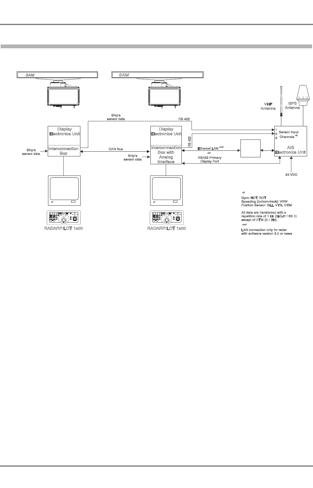
2.2 AIS 3410 in RADARPILOT 1000/1100 Systems
Fig. 2-1 AIS 3410 in RADARPILOT 1000/1100 systems
The AIS 3410 is connected to the Interconnection Box of the RADARPILOT 1000/1100. The ship’s
sensors are connected to the radar(s). The sensor data are transferred from the radar(s) to the AIS (in
dual or multiple installations, from two radars as redundancy, if possible).
The repetition interval of the ship’s sensor data is set automatically if the indicator’s serial interface is
configured as AIS Navigation Data interface.
If the RADARPILOT 1000/1100 has a software of version 3.0 or newer, it is also possible to connect the
AIS by means of the Ethernet LAN.
Interconnection
Box
RADARPILOT 1x00 RADARPILOT 1x00
Interconnection
Box with
Analog
Interface
VHF
Antenna
Ship's
sensor dataShip's
sensor data
Gyro: HDT, ROT
Speedlog (bottom-track): VBW
Position Sensor: GLL, VTG, DTM
All data are transferred with a
repetition rate of 1 Hz (IEC 61162-1)
except of DTM (0.1 Hz)
*
)
LAN connection only for radar
with software version 3.0 or newe
r.
**
)
Ship's
sensor data
CAN Bus
Sensor Input
Channels
*
)
1
2
3
RS422 Primary
Display Port
Ethernet LAN
**
)
or
RS 422
RS 422
Display
Electronics Unit
Display
Electronics Unit
AIS
Electronics Unit
SAM
SAM
24 VDC
GPS
Antenna
Media
Converter
RJ-45
BNC
z_ue_006odcu.pdf
AIS 3410, Electronics Unit
ED3047G842 / 01 (2009-08)
Technical Manual
2 Overview
2.3 AIS 3410 in 1000/1100 Series Systems (NACOS xx-4 and xx-5)
t_ue_e02.fm / 27.08.09
13
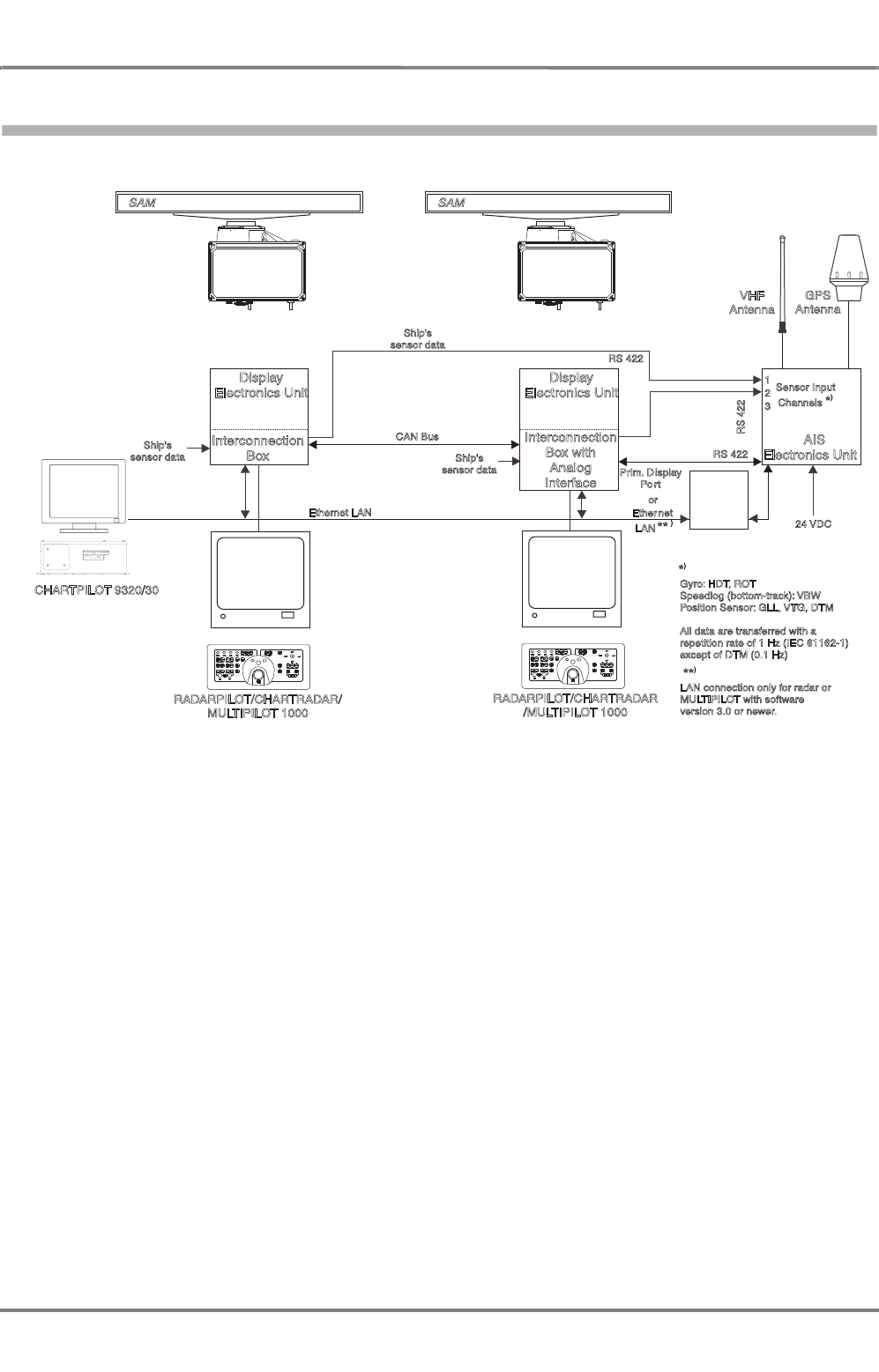
2.3 AIS 3410 in 1000/1100 Series Systems (NACOS xx-4 and xx-5)
Fig. 2-2 AIS 3410, SAM Electronics 1000/1100 series systems (NACOS xx-4/NACOS xx-5)
The AIS 3410 is connected to the Interconnection Box of the RADARPILOT/CHARTRADAR 1000/1100.
The ship’s sensors are connected to the radars. The sensor data are transferred from the radar(s) to the
AIS (in dual or multiple installations, from two radars as redundancy, if possible).
The repetition interval of the ship’s sensor data is set automatically if the indicator’s serial interface is
configured as AIS Navigation Data interface.
If the RADARPILOT 1000 and/or MULTIPILOT 1000 has a software of version 3.0 or newer, it is also
possible to connect the AIS by means of the Ethernet LAN (always possible in 1100 series systems).
All CHARTPILOT systems receive the AIS data via the Ethernet LAN. If the AIS Electronics Unit is not
connected to the LAN, only the activated targets can be displayed at the CHARTPILOT. If the AIS Elec-
tronics Unit is connected to the LAN and a Software Version 5.2 or newer is installed on the CHART-
PILOT, the complete AIS functionality is available at the CHARTPILOT (always fulfilled at CHARTPILOT
1100).
Interconnection
Box
Interconnection
Box with
Analog
Interface
VHF
Antenna
CHARTPILOT 9320/30
RADARPILOT/CHARTRADAR/
MULTIPILOT 1000
RADARPILOT/CHARTRADAR
/MULTIPILOT 1000
Ethernet LAN
Ship's
sensor dataShip's
sensor data
Ship's
sensor data
CAN Bus
RS 422
RS 422
RS 422
Display
Electronics Unit
Display
Electronics Unit
AIS
Electronics Unit
GPS
Antenna
SAM
Prim. Display
Po rt
Ethernet
LAN
**
or
Sensor Input
Channels
*
)
1
2
3
*
)
Gyro: HDT, ROT
Speedlog (bottom-track): VBW
Position Sensor: GLL, VTG, DTM
All data are transferred with a
repetition rate of 1 Hz (IEC 61162-1)
except of DTM (0.1 Hz)
24 VDC
LAN connection only for radar or
MULTIPILOT with software
version 3.0 or newer.
**
)
SAM
/1100 /1100
Media
Converter
RJ-45
BNC
z_ue_007odcu.pdf
AIS 3410, Electronics Unit
ED3047G842 / 01 (2009-08)
Technical Manual
2 Overview
2.4 AIS 3410 in CHARTPILOT Stand-alone Systems
t_ue_e02.fm / 27.08.09
14
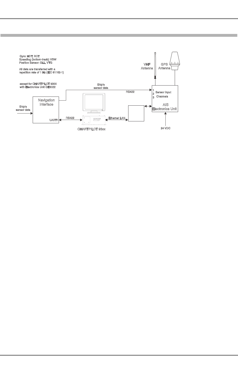
2.4 AIS 3410 in CHARTPILOT Stand-alone Systems
Fig. 2-3 AIS 3410 with CHARTPILOT stand-alone
The AIS 3410 is connected to the CHARTPILOT via Ethernet LAN. The ship’s sensors are connected to
the Navigation Interface. The sensor data are transferred to the CHARTPILOT via an RS422 interface.
NOTE:
If the AIS Electronics Unit receives the ship’s sensor data from Ship’s Interface, the output interfaces of
the Ship’s Interface must be configured as follows:
- Select "IEC 61162-1 edition 3, 04/2007 (NMEA0183 version 3.01)" as driver
- Set a repetition interval of 1 s for the following telegrams:
-GLL
-VTG
- HDT
-ROT
- VBW (if bottom-track log is available)
VHF
Antenna
CHARTPILOT 93xx
Ethernet LAN
Ship's
sensor data
Ship's
sensor data
RS422
RS422
UART1
AIS
Electronics Unit
Navigation
Interface
GPS
Antenna
Sensor Input
Channels
1
2
3
Gyro: HDT, ROT
Speedlog (bottom-track): VBW
Position Sensor: GLL, VTG
All data are transferred with a
repetition rate of 1 Hz (IEC 61162-1)
except for CHARTPILOT 9300
with Electronics Unit GE3022
24 VDC
Media
Converter
RJ-45
BNC
*
*
**
**
z_ue_008odcu.pdf
AIS 3410, Electronics Unit
ED3047G842 / 01 (2009-08)
Technical Manual
2 Overview
2.5 AIS 3410 in NACOS xx-3 Systems (Radar 9xxx and CHARTPILOT)
t_ue_e02.fm / 27.08.09
15
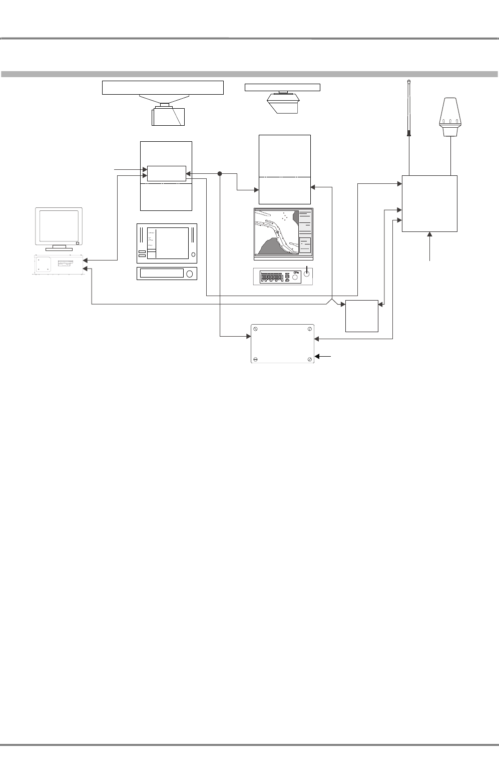
2.5 AIS 3410 in NACOS xx-3 Systems (Radar 9xxx and CHARTPILOT)
Fig. 2-4 AIS 3410 in NACOS xx-3 systems
The AIS 3410 is connected to the CHARTPILOT via Ethernet LAN.
The ship’s sensors are connected to the Ship’s Interface. The sensor data are transferred to the AIS, to
the CHARTPILOT and to other radars or MULTIPILOTs.
If two Ship’s Interfaces are existing because of redundancy purposes, the ship’s sensor output(s) of both
Ship’s Interfaces must be connected to the Electronics Unit.
Without the Radar 9xxx AIS Interface it is not possible to display the AIS data at the Radar 9xxx or at the
MULTIPILOT 91x0 in radar mode. One interface is sufficient for the complete system, regardless of the
number of Radars 9xxx/MULTIPILOTs.
NOTE:
If the AIS Electronics Unit receives the ship’s sensor data from Ship’s Interface, the output interfaces of
the Ship’s Interface must be configured as follows:
- Select "IEC 61162-1 edition 3, 04/2007 (NMEA0183 version 3.01)" as driver
- Set a repetition interval of 1 s for the following telegrams:
-GLL
-VTG
-HDT
-ROT
- VBW (if bottom-track log is available)
z_ue_009.pdf
VHF
Antenna
VHF
Antenna
CHARTPILOT 93xxCHARTPILOT 93xx
MULTIPILOT 910xMULTIPILOT 910x
Radar 9xxxRadar 9xxx
AIS
Electronics Unit
AIS
Electronics Unit
GPS
Antenna
GPS
Antenna
SAMSAM
SAMSAM
Ship's
sensor data
Ship's
sensor dataShip's
sensor data
Ship's
sensor data
Ship's
sensor data
Ship's
sensor data
CAN 1
Ethernet LANEthernet LAN
RS422RS422
RS422RS422
Electronics
Unit
Electronics
Unit
Electronics
Unit
Electronics
Unit
TransceiverTransceiver TransceiverTr ansceiver
Ship's
Interface
Gyro: HDT, ROT
Speedlog (bottom-track): VBW
Position Sensor: GLL, VTG
All data are transferred with a
repetition rate of 1 Hz (IEC 61162-1)
Gyro: HDT, ROT
Speedlog (bottom-track): VBW
Position Sensor: GLL, VTG
All data are transferred with a
repetition rate of 1 Hz (IEC 61162-1)
Sensor Input
Channels
Sensor Input
Channels
1
2
3
except for CHARTPILOT 9300
with Electronics Unit GE3022
except for CHARTPILOT 9300
with Electronics Unit GE3022
24 VDC
Radar 9xxx
AIS
Interface
Radar 9xxx
AIS
Interface Ship's mainsShip's mains
Media
Converter
RJ-45
BNC
*
***
**
AIS 3410, Electronics Unit
ED3047G842 / 01 (2009-08)
Technical Manual
2 Overview
2.6 AIS 3410 in Radar 9xxx Systems with RADARPILOT 1000/1100
t_ue_e02.fm / 27.08.09
16
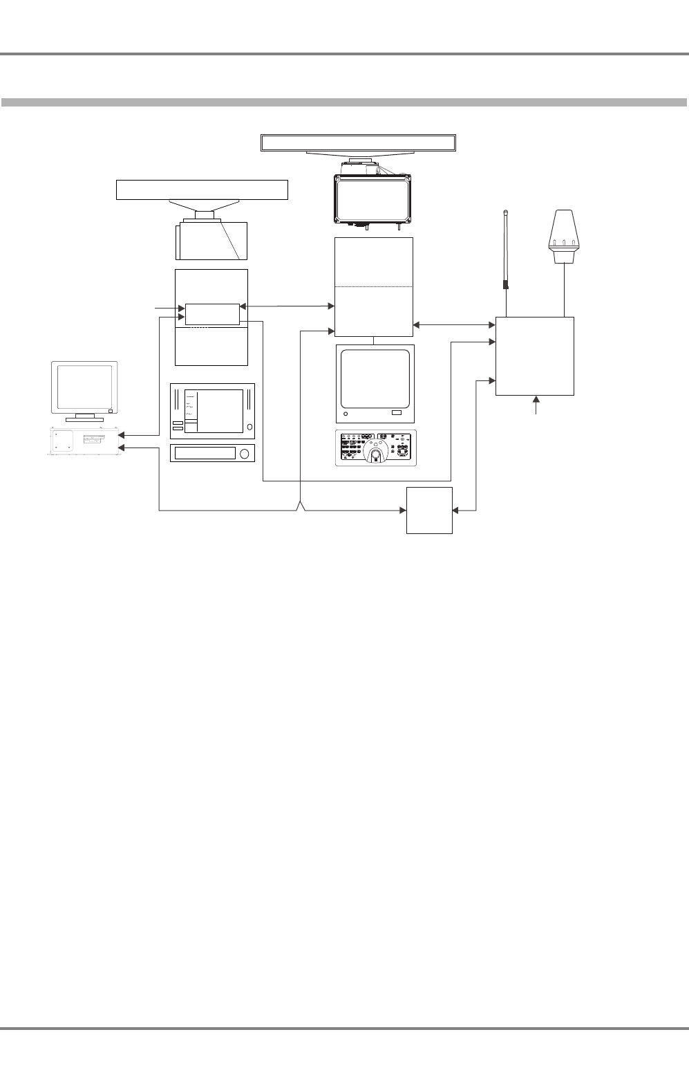
2.6 AIS 3410 in Radar 9xxx Systems with RADARPILOT 1000/1100
Fig. 2-5 AIS 3410 in Radar 9xxx systems with RADARPILOT 1000/1100
The AIS 3410 is connected to the CHARTPILOT via Ethernet LAN and to the Analog Interface of the
RADARPILOT 1000/1100. The RADARPILOT 1000/1100 transfers the AIS data via CAN1, so that the
data can be displayed also at the Radar 9xxx (or at a MULTPILOT 91x0). It is not necessary to install
the Radar 9xxx AIS Interface. If the RADARPILOT 1000/1100 is connected via LAN instead of Primary
Display Port, the AIS data is not available on CAN1 for the Radar 9xxx.
The ship’s sensors are connected to the Ship’s Interface. The sensor data are transferred to the AIS, to
the CHARTPILOT and to a MULTIPILOT.
NOTE:
If the AIS Electronics Unit receives the ship’s sensor data from Ship’s Interface, the output interfaces of
the Ship’s Interface must be configured as follows:
- Select "IEC 61162-1 edition 3, 04/2000 (NMEA0183 version 3.01)" as driver
- Set a repetition interval of 1 s for the following telegrams:
-GLL
-VTG
- HDT
-ROT
- VBW (if bottom-track log is available)
z_ue_010.pdf
VHF
Antenna
VHF
Antenna
RADARPILOT 1000/1100
RADAR 9xxxRADAR 9xxx
AIS
Electronics Unit
AIS
Electronics Unit
GPS
Antenna
GPS
Antenna
SAMSAM
Ship's
sensor data
Ship's
sensor dataShip's
sensor data
Ship's
sensor data
CAN 1
RS422, PrimaryRS422, Primary
Display PortDisplay Port
Ethernet LAN
RS422RS422
RS422RS422
Electronics
Unit
Electronics
Unit
TransceiverTransceiver
Ship's
Interface
Interconnection
Box with
Analog
Interface
Interconnection
Box with
Analog
Interface
Display
Electronics Unit
Display
Electronics Unit
SAMSAM
Sensor Input
Channels
Sensor Input
Channels
1
2
3
Gyro: HDT, ROT
Speedlog (bottom-track): VBW
Position Sensor: GLL, VTG
All data are transferred with a
repetition rate of 1 Hz (IEC 61162-1)
Gyro: HDT, ROT
Speedlog (bottom-track): VBW
Position Sensor: GLL, VTG
All data are transferred with a
repetition rate of 1 Hz (IEC 61162-1)
CHARTPILOT 93xxCHARTPILOT 93xx
except for CHARTPILOT 9300
with Electronics Unit GE3022
except for CHARTPILOT 9300
with Electronics Unit GE3022
24 VDC
Media
Converter
RJ-45
BNC
*
*
**
**
AIS 3410, Electronics Unit
ED3047G842 / 01 (2009-08)
Technical Manual
2 Overview
2.7 AIS 3410 in Radar 9xxx Systems
t_ue_e02.fm / 27.08.09
17
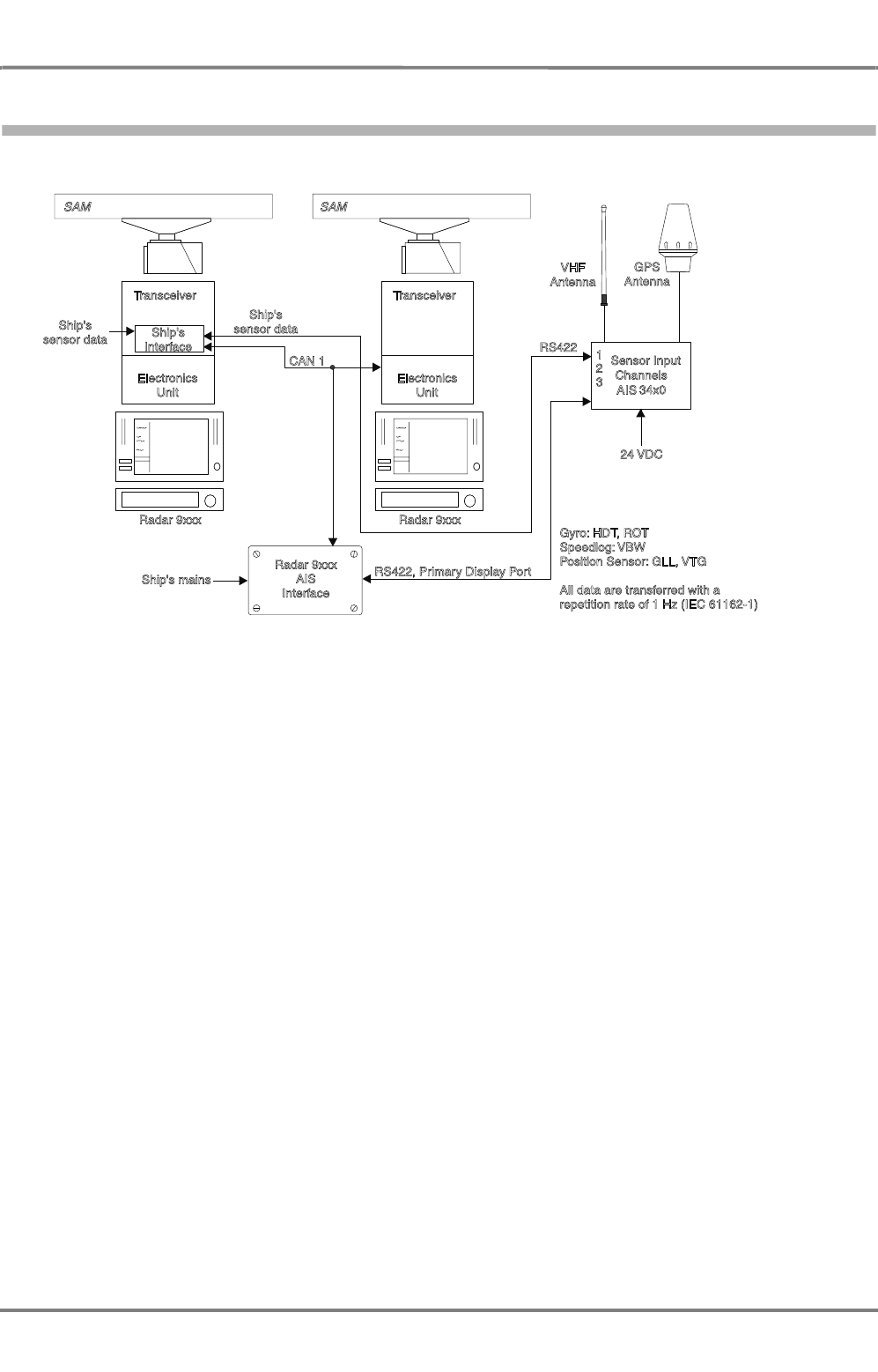
2.7 AIS 3410 in Radar 9xxx Systems
Fig. 2-6 AIS 3410 in Radar 9xxx systems
The AIS 3410 is connected to the Ship’s Interface by means of the additional Radar 9xxx AIS Interface.
For further information see the Technical Manual of the Radar 9xxx AIS Interface. The cabling diagrams
are shown in Section 9.
The ship’s sensors are connected to the Ship’s Interface. The sensor data are transferred to the AIS and
to the radars. If an additional CHARTPILOT is connected, the AIS 3410 is connected to the CHART-
PILOT via Ethernet LAN.
NOTE:
If the AIS Electronics Unit receives the ship’s sensor data from Ship’s Interface, the output interfaces of
the Ship’s Interface must be configured as follows:
- Select "IEC 61162-1 edition 3, 04/2007 (NMEA0183 version 3.01)" as driver
- Set a repetition interval of 1 s for the following telegrams:
-GLL
-VTG
-HDT
-ROT
- VBW (if bottom-track log is available)
z_ue_044odcu.pdf
VHF
Antenna
Radar 9xxx Radar 9xxx
AIS34x0
GPS
Antenna
SAM SAM
Ship's
sensor data
Ship's
sensor data
CAN 1
RS422
Electronics
Unit
Electronics
Unit
Transceiver
Transceiver
Ship's
Interface
Gyro: HDT, ROT
Speedlog: VBW
Position Sensor: GLL, VTG
All data are transferred with a
repetition rate of 1 Hz (IEC 61162-1)
Sensor Input
Channels
1
2
3
24 VDC
RS422, Primary Display Port
Radar 9xxx
AIS
Interface
Ship's mains
*
*
AIS 3410, Electronics Unit
ED3047G842 / 01 (2009-08)
Technical Manual
2 Overview
2.8 Housing of the 3410 Electronics Unit
t_ue_e02.fm / 27.08.09
18
2.8 Housing of the 3410 Electronics Unit
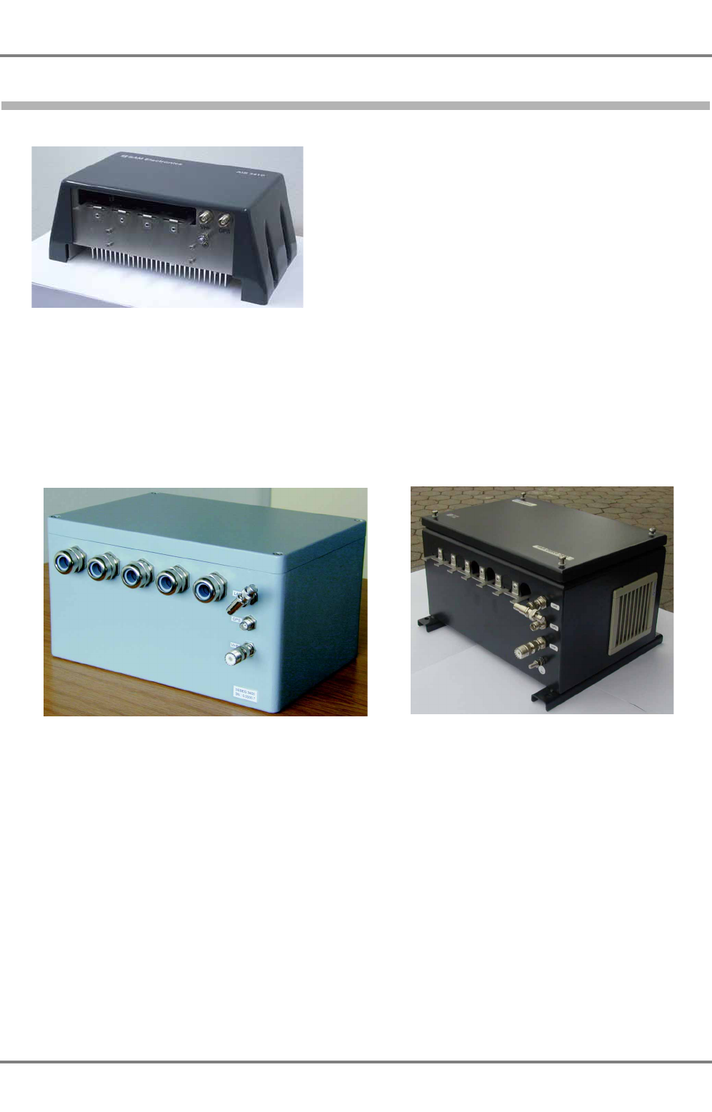
Fig. 2-7 AIS 3410 Electronics Unit (current version)
The plastic housing of the 3410 contains a single Electronics Unit which consists of the controller, the
interfaces, the VHF transmitter/receiver and the GPS receiver. The Electronics Unit has five cable inlets
for ship’s cables and two coaxial connectors for the connection of GPS and VHF antennas. One of the
five cable inlets will be used for the Ethernet LAN (RJ-45) connector, being inside the housing of the Elec-
tronics Unit.
Fig. 2-8 UAIS DEBEG 3400 Electronics Unit (old versions)
The aluminium housing contains a single Electronics Unit which consists of the controller, the interfaces,
the VHF transmitter/receiver and the GPS receiver. The UAIS DEBEG 3400 version of the housing has
five cable glands for ship’s cables and three coaxial connectors for the connection of Ethernet LAN
(BNC), GPS and VHF antennas. The UAIS DEBEG 3400 version (steel housing) has cable inlets instead
of the cable glands.
z_ue_012.tif
z_ue_037.jpg
AIS 3410, Electronics Unit
ED3047G842 / 01 (2009-08)
Technical Manual
2 Overview
2.9 Replacement of AIS Electronics Unit
t_ue_e02.fm / 27.08.09
19
2.9 Replacement of AIS Electronics Unit
In case of replacing the UAIS DEBEG 3400 Electronics Unit with a AIS 3410 Electronics Unit there is no
need to remove the old housing. Therefore proceed as described below. To ensure the correct display of
all data please refer to Technote T-0908-3400-023.
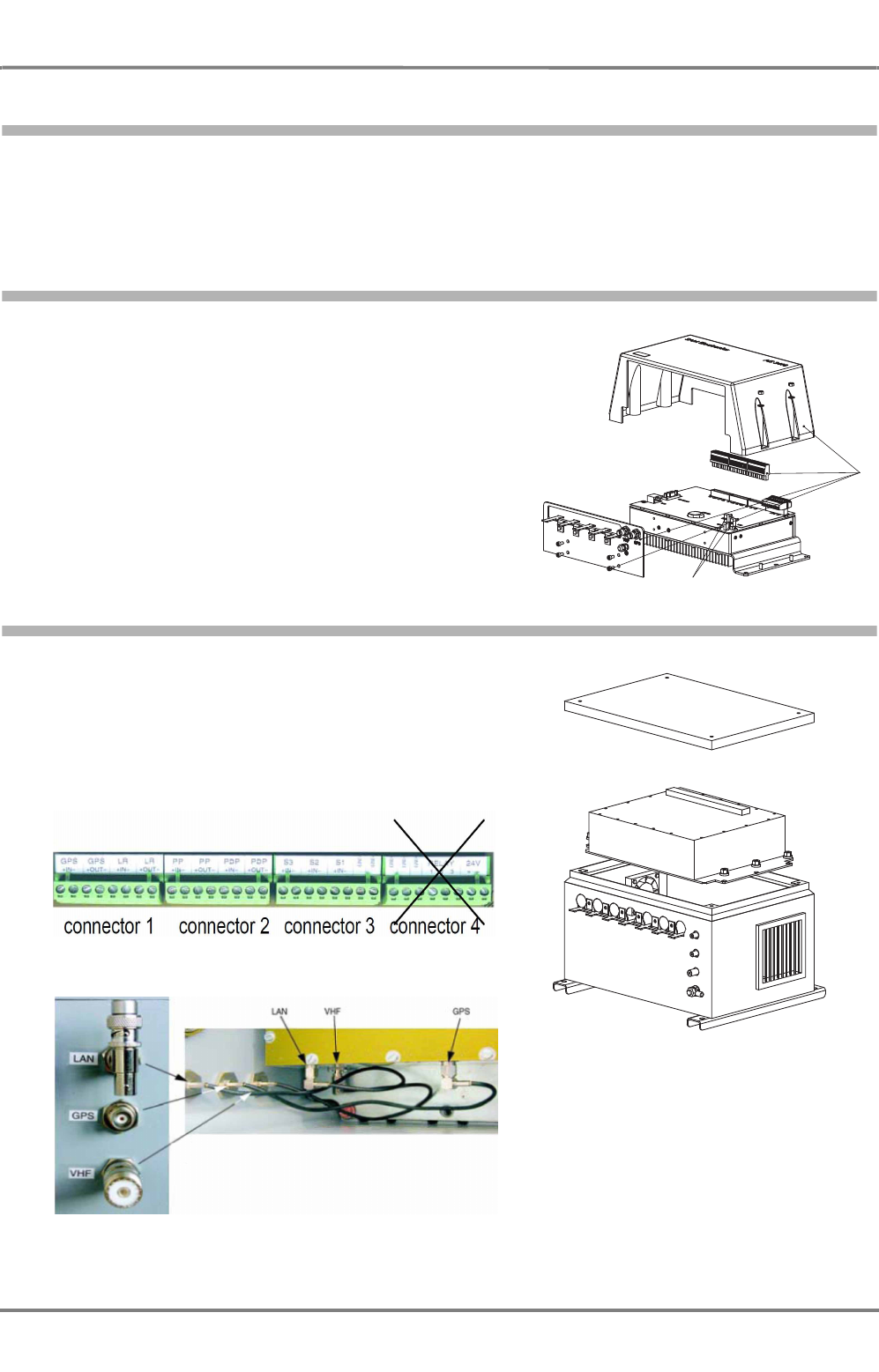
2.9.1 Open the Housing of AIS 3410
1. Remove these parts from the AIS 3410.
2. Disconnect the GPS and the VHF connecting cable.
2.9.2 Open the Housing of UAIS DEBEG 3400
1. Disconnect the UAIS DEBEG 3400 from power
supply.
Undo all ship cables from the bracket.
Disconnect the Phoenix plugs from the Electronics
Unit.
Unplug the cables form the Phoenix plug (connector
4) and remove the Phoenix plug.
2. Disconnect the LAN-, VHF- and GPS connecting
cable from the Electronics Unit.
3. Dismount the Electronics Unit and remove it.
1.
2.
AIS 3410, Electronics Unit
ED3047G842 / 01 (2009-08)
Technical Manual
2 Overview
2.10 Media Converter Installation (necessary for ships with BNC LAN networks)
t_ue_e02.fm / 27.08.09
20
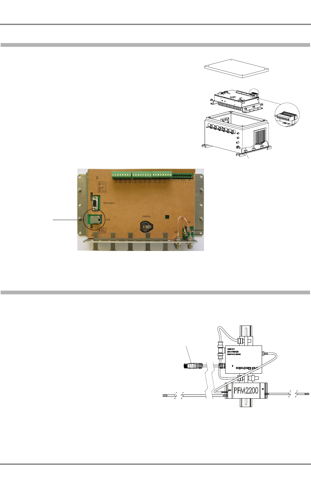
2.9.3 Merge the AIS 3410 Electronics Unit into the UAIS DEBEG 3400 Housing
1. Insert the Electronics Unit from the AIS 3410 and
mount it on the distance bolts with the six M6 nuts.
2. Take the new Phoenix plug (connector 4) and
connect the cables again.
Connect to the 24V interface the cables from24V
power supply, fan and media converter.
3. Connect the GPS- and the VHF connecting cable to
the internal GPS- and VHF-connector.
The LAN network has to be connected via the media
converter.
The coaxial connector of Ethernet LAN, mounted on
the housing, cannot be used any more
(GE4034G010, Mat-Nr.: 271259883).
4. Fasten all ship cables at the bracket again.
Fig. 2-9 AIS 3410 Electronics Unit (without housing)
2.10 Media Converter Installation (necessary for ships with BNC LAN networks)
The media converter has to be installed between the AIS 3410 and the BNC LAN plug of the ship´s
network.
1. Mount the mounting plate including the media
converter on the wall or on the ground near
to the AIS 3410 Electronics Unit.
2. Put the BNC LAN plug of the ship´s network
into the BNC jack of the media converter.
3. Put one side of the Ethernet LAN cable (with
2 RJ-45 plugs) into the RJ-45 jack of the
media converter.
4. Undo the 4 screws of the casing cover of the
AIS 3410 and take the casing cover off.
5. Put the other side of the Ethernet LAN cable
into the LAN jack of the AIS 3410 rear panel
(Figure 2-9).
6. Put the casing cover on and fasten the 4
screws.
distance bolt
new Phoenix plug
GPS
VHF
LAN
to scale
Drawing is not true
RJ-45 (connection to AIS 3410)

AIS 3410, Electronics Unit
ED3047G842 / 01 (2009-08)
Technical Manual
3 Installation Recommendations
3.1 General Recommendations
t_ue_e03.fm / 27.08.09
21
3 Installation Recommendations
3.1 General Recommendations
3.1.1 Cables
Cable types, cable data, maximum cable length, special instructions for cable laying and connection
details are defined in the Cabling Documents of the corresponding equipment (consisting of schematic
diagram, remarks, cable list and connection diagram).
Interface connections should be discussed and agreed with SAM Electronics
In order to ensure proper functioning of the equipment, the cable types should be selected according to
the cable lists.
In general, the following points must be taken into account:
-For the cables inside the units (cabinets), an extra length of 1 metre is necessary at each end. If
the height of the unit exceeds 0.5 metre, an extension by 1 m plus the height of the cabinet is neces-
sary.
- All cables should be kept as short as possible, especially coaxial cables to minimize attenuation of
signal.
In order to fulfil all abovementioned requirements, install cables in two steps:
Install cables and leave extra length of 1 metre or more as described above
Cut cables to correct length in order to reach its terminal, but do not leave extra lengths furled
inside or outside the cabinet
-The cables must be marked by the electrician at both ends with the cable numbers corresponding
to the SAM Electronics cabling documents.
- Where necessary, particular cable glands - marked with letters and/or numbers - are assigned to
the cables.
The identification letters and numbers are stated in the connection diagrams; they are either fixed to
the unit or can be seen from the outline drawings (...BZ or ...MB).
- All connectors installed outdoors (e.g. on coaxial cables) should be waterproof by design to protect
against water penetration into the cable.
- Coaxial cables should be installed in separate signal cable channels/tubes and at least 10 cm away
from power supply cables. Crossing of cables should be done at right angles (90°). Coaxial cables
should not have any to sharp bends, which may lead to a change in the characteristic impedance of
the cable. The minimum bend radius should be 5 times the cable’s outside diameter.
- It must be ensured that all cables - including their screens - are passed into the units in contin-
uous lengths and are not terminated before reaching the destination equipment.
-With multicore cables, it is useful to strip down and lace the single wires according to the terminal
sequence.
- Existing cable grippers in the units must be used.
- All cable connections must be carefully checked after completion of the cable work and all cable
screens must be grounded via the shortest possible connections - if not stated otherwise in the
Cabling Documents/Connection Diagram.
AIS 3410, Electronics Unit
ED3047G842 / 01 (2009-08)
Technical Manual
3 Installation Recommendations
3.1 General Recommendations
t_ue_e03.fm / 27.08.09
22
- All cables must be secured by means of suitable clamps (pull-relief) before entering the units.
- It must be ensured that cables do not block any moving parts within a unit.
-Power leads must be protected by "slow-blow" fuses according to their cross section.
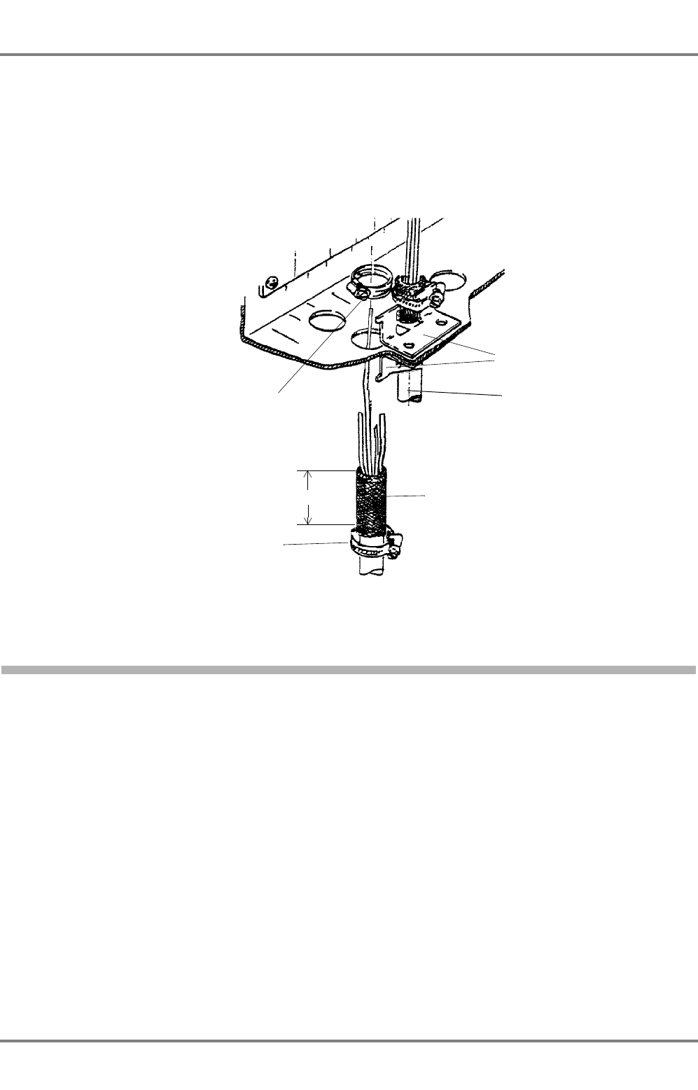
- In the case of a unit whose cable inlet consists of a hole with brackets attached on the inside
and outside, the cable must be dressed as shown in Figure 3-1.
Fig. 3-1 Cable inlet consisting of a hole with brackets
3.1.1.1
Maximum Cable Length
Coaxial Antenna Cable for the VHF Antenna
The maximum length of this cable (LCF 12-50) is 80 m. See Section 9,
Cabling Documents
.
Coaxial Cable for the GPS Antenna
The length of this cable is defined by the cable sets. Prefabricated cables with a length of 20, 30, or 40 m
can be delivered.
If a length of more than 40 m is needed, the cable LCF 12-50 of the VHF antenna must be used in combi-
nation with TNC-N plug adapters. See Section 9,
Cabling Documents
.
Ethernet LAN
The Ethernet LAN thin wire cabling (RG-213/U ship’s cable or RG58) must not exceed a length of 185 m.
Screen braid laid back over outer sheathing;
contact with the brackets via metal clamp
Installation cables
FMGCH, FMKHC MGCH etc.
z_ue_072.gif
Metal clamp inside
Metal clamp outside
35+5
Brackets

AIS 3410, Electronics Unit
ED3047G842 / 01 (2009-08)
Technical Manual
3 Installation Recommendations
3.1 General Recommendations
t_ue_e03.fm / 27.08.09
23
3.1.1.2
Cable Sets
The following cable sets are available:
3.1.2 Electronics Units
Dimensions, weights, spaces required for service and maintenance and special installation instructions
are stated in the outline drawings and installation drawings of the corresponding unit. In general, the
following points also apply:
- The useful life of the components of all Electronics Units (Pulse Generators, Transceivers etc.)
generally decreases with increasing ambient temperature; it is therefore advisable to install such
units in air-conditioned rooms. If there are no such facilities - e.g. deckhouse or space near or below
the water line - these rooms must at least be dry, adequately ventilated and kept at a suitable
temperature in order to prevent the formation of condensation inside these units.
- With most Electronics Units, cooling takes place via the surface of the casing.
The cooling must not be impaired by partial covering of the unit as a result of insulation (if any) of
the room (the wall on which the casing is mounted), or by installation of the unit in a confined
cabinet.
Furthermore, the distance from the ceiling and the floor or from a unit situated underneath must be
at least 300 mm.
- For service purposes, a power socket (AC 220/230 V) and adequate lighting are necessary in the
vicinity of each Electronics Unit.
- In the area of the wheel house, the distance of each Electronics Unit from the magnetic
standard compass or the magnetic steering compass must not be less than the permitted
magnetic protection distance.
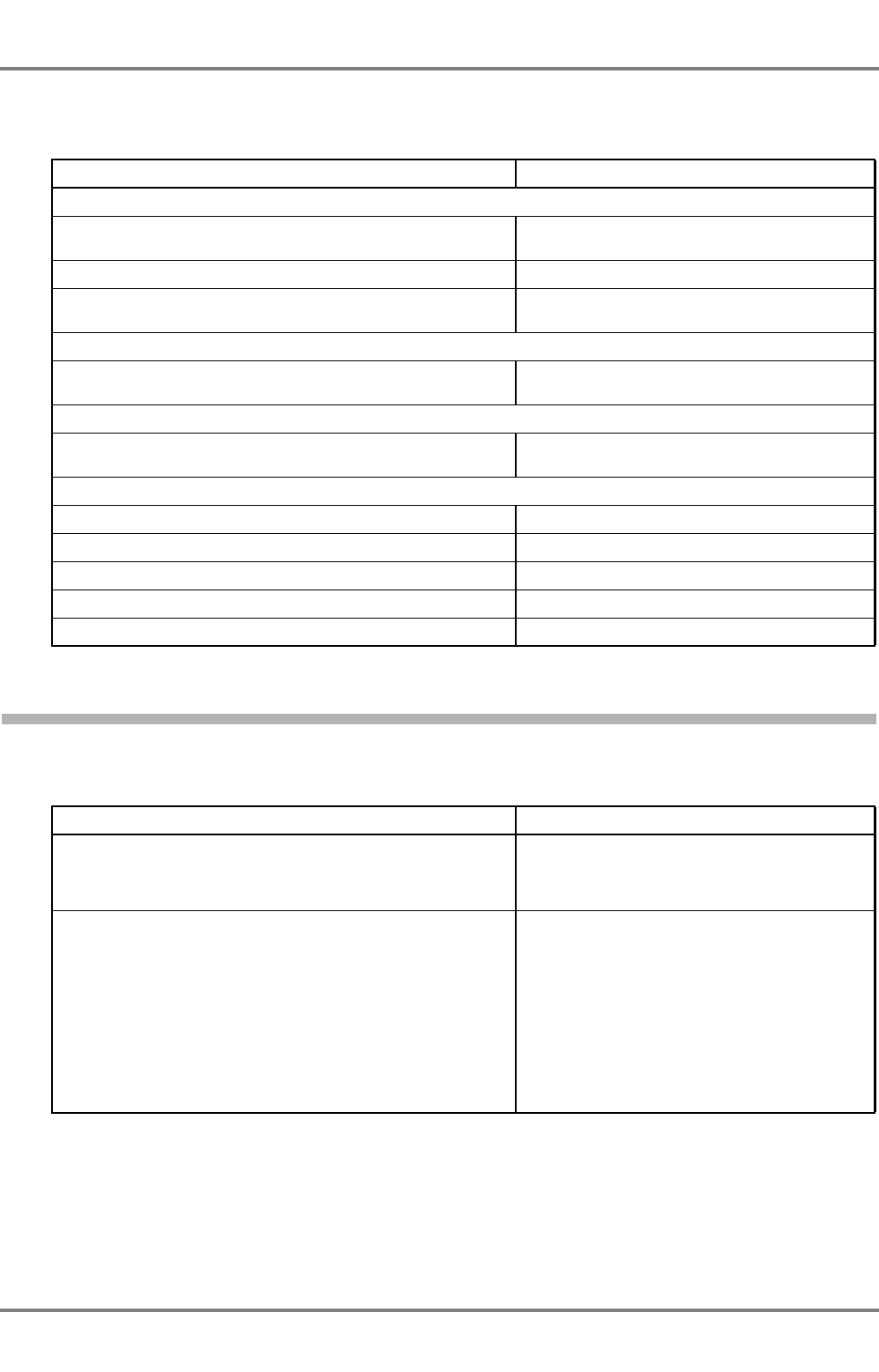
Purpose/Description Quantity/m Order No.
LAN network, cable RG 213/U, 2 BNC
connectors on request 300005394
Connection of the GPS antenna, cable
HF2,3LZ/7,3DZ with 2 plugs 11TNC-50-7-
2C
20 271256324
Connection of the GPS antenna, cable
02Y(ST)C2Y2.7/7.3AF with 2 TNC plugs 30 300005391
Connection of the GPS antenna, cable
02Y(ST)C2Y2.7/7.3AF with 2 TNC plugs 40 300005392
For the connection of the GPS antenna with
cable length >40 m, cable of type Cellflex
LCF 12-50 50 Ω must be used.
on request 271257679
Connection of the VHF antenna, cable
HF2,3LZ/7,3DZ with 2 plugs 11TNC-50-7-
2C
20 271256324
Connection of the VHF antenna, cable
02Y(ST)C2Y2.7/7.3AF with 2 TNC plugs 30 300005391
Connection of the VHF antenna, cable
02Y(ST)C2Y2.7/7.3AF with 2 TNC plugs 40 300005392
For the connection of the VHF antenna with
cable length >40 m, cable of type Cellflex
LCF 12-50 50 Ω must be used.
on request 271257679

AIS 3410, Electronics Unit
ED3047G842 / 01 (2009-08)
Technical Manual
3 Installation Recommendations
3.2 Specific Recommendations
t_ue_e03.fm / 27.08.09
24
This distance is measured from the centre of the magnetic system of the compass to the nearest
point on the corresponding unit concerned.
- Units which are to be used on the bridge wing must be installed inside the "wing control console" -
protected against the weather - if they do not at least correspond to the enclosure type IP 56. In
order to avoid misting of the viewing screen, 25 ... 50 W console-heating (power depending on the
volume) is recommended.
- When selecting the site of a unit, the maximum cable lengths have to be considered according to
the notes in the cabling documents (remarks, cable list).
-The accessibility for maintenance and service (stated in the outline drawings or installation draw-
ings) must be considered.
- The impairment of a digital read-out or a display screen by direct light from lamps or the sun must
be avoided. Rear windows must be blacked out by means of roller blinds or Venetian blinds.
-Disturbing reflections on the screen of a display caused by pilot lamps and illuminated signs must
be prevented by suitable measures (screening or relocating).
- When a unit is being installed, the base, floor or bulkhead must be checked to ensure that it is
flat in order to avoid twisting of the unit when the fixing screws are tightened, because such twisting
would impair mechanical functions. Any unevenness should be compensated for by means of
spacing-washers.
-The grounding screws of the units must be connected to the body of the ship (ground); the wire
used should have a cross sectional area of at least 6 mm.
Aboard fibreglass (GRP) vessels, a "grounding network" with a high conductance - taking into
consideration the working frequencies of the other equipment - must be provided in order to achieve
satisfactory EMC (electromagnetic compatibility).
- In the interests of safety during maintaining or servicing, the shipyard should provide a common
isolating switch or circuit breaker (in conjunction with a contactor, if necessary) for all intercon-
nected equipment.
-Transportation damage, even if apparently insignificant at first glance, must immediately be exam-
ined and be reported to the freight carrier. The moment of setting-to-work of the equipment is too
late, not only for reporting the damage but also for the supply of replacements.
-The equipment should never be switched on by the electricians who did the installation work
- not even just for a moment - never!
This is a job for the authorised SAM Electronics service engineer.
-After hand-over of the equipment in good operating condition to the customer, the Installation
Report (Annex of the Warranty Certificate) should be filled in completely and then forwarded to SAM
Electronics, Hamburg, as proof of such fulfilment. It is important that these requirements be fulfilled
in order to avoid the risk of losing the warranty.
3.2 Specific Recommendations
3.2.1 Recommendations Concerning AIS Systems
Recommendations for the installation of AIS systems are published in the document IMO Circular SN227
"Guidelines for the Installation of a Shipborne Automatic Identification System (AIS)". See this document
for further information. The following sections also contain information which has been taken from this
document.
AIS 3410, Electronics Unit
ED3047G842 / 01 (2009-08)
Technical Manual
3 Installation Recommendations
3.2 Specific Recommendations
t_ue_e03.fm / 27.08.09
25
3.2.2 Recommendations Concerning the Installation of the Electronics Unit
The Electronics Unit should be mounted on a vertical bulkhead. A distance of at least 300 mm from other
devices must be ensured around the housing for sufficient air circulation. See also Section 10,
Outline
Drawings
.
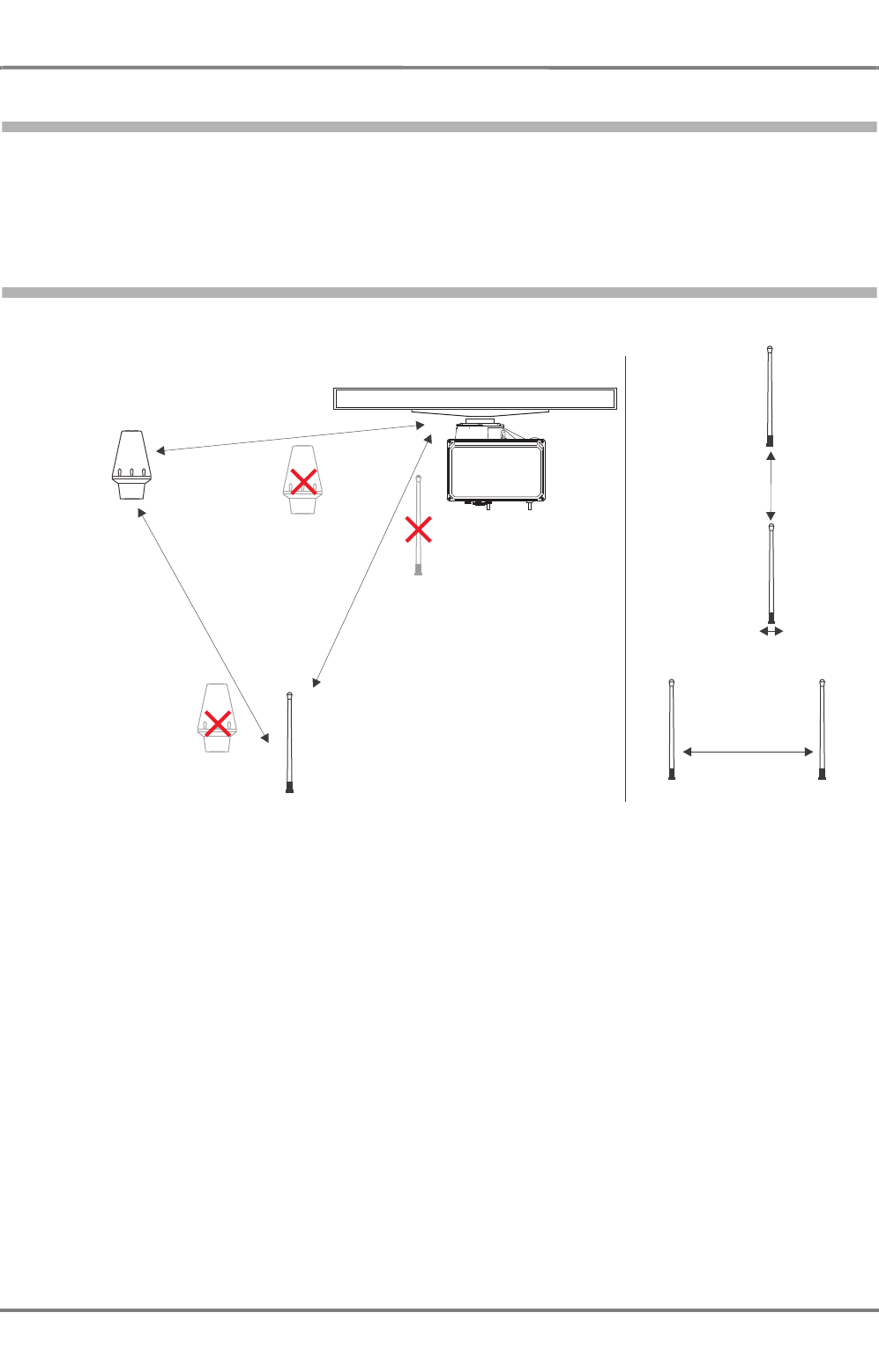
3.2.3 Recommendations Concerning the Installation of the Antennas
Fig. 3-2 Minimum distances for GPS and VHF Antenna
VHF
Antenna
VHF
Antenna
AIS VHF
Antenna
AIS VHF
Antenna
Primary
radiotelephone
VHF Antenna
Primary
radiotelephone
VHF Antenna
Primary
radiotelephone
VHF Antenna
Primary
radiotelephone
VHF Antenna
AIS
VHF Antenna
AIS
VHF Antenna
or
>3 m
>3 m
>2 m
0 m
>10 m
>3 m
GPS
Antenna
GPS
Antenna
SAM
z_ue_040.eps
AIS 3410, Electronics Unit
ED3047G842 / 01 (2009-08)
Technical Manual
3 Installation Recommendations
3.2 Specific Recommendations
t_ue_e03.fm / 27.08.09
26
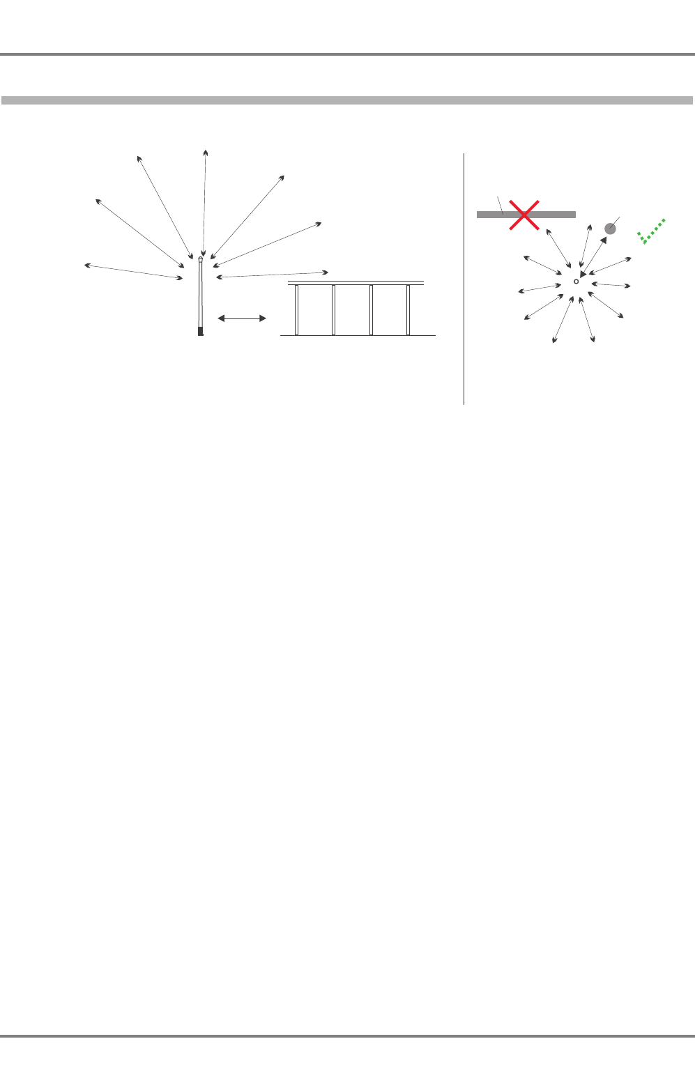
3.2.3.1
Recommendations Concerning the Installation of the VHF Antenna
Fig. 3-3 Positioning of the VHF Antenna
The digital signals of the AIS may occur as a periodic clicking sound on a ship’s radiotelephone. This
effect may become stronger when the VHF antenna of the AIS is located near the VHF radiotelephone
antenna and when the radiotelephone is operating on channels near the AIS operating channels (for
example channels 27, 28, 86).
The antenna should be placed in an elevated position that is as unobstructed as possible, with a
minimum of 2 m in the horizontal direction from any structures made of conductive materials. The
antenna should not be installed close to any large vertical obstruction. The objective for the VHF antenna
is that it should "see" the horizon freely through 360°.
The VHF antenna should be installed safely away from interfering high-power energy sources such as
the radar scanner and other transmitting radio antennas, preferably at least 3 m away from and out of the
transmitting beam.
Ideally there should not be more than one antenna on the same level. The AIS VHF antenna should be
mounted directly above or below the ship’s primary VHF radiotelephone antenna, with no horizontal sepa-
ration and with a minimum of 2 m vertical separation. If it is located on the same level as other antennas,
the distance apart should be at least 10 m.
For further information, see Figure on page 82.
AIS VHF
Antenna
AIS VHF
Antenna
360° view
>2 m
>2 m
Mast, boom, railing
with small diameter
(should be avoided)
Mast, boom, railing
with small diameter
(should be avoided)
Side view Top view
Conductive superstructures
Superstructures,
e.g. deck house,
funnel,
Superstructures,
e.g. deck house,
funnel,
z_ue_041.eps
AIS 3410, Electronics Unit
ED3047G842 / 01 (2009-08)
Technical Manual
3 Installation Recommendations
3.2 Specific Recommendations
t_ue_e03.fm / 27.08.09
27
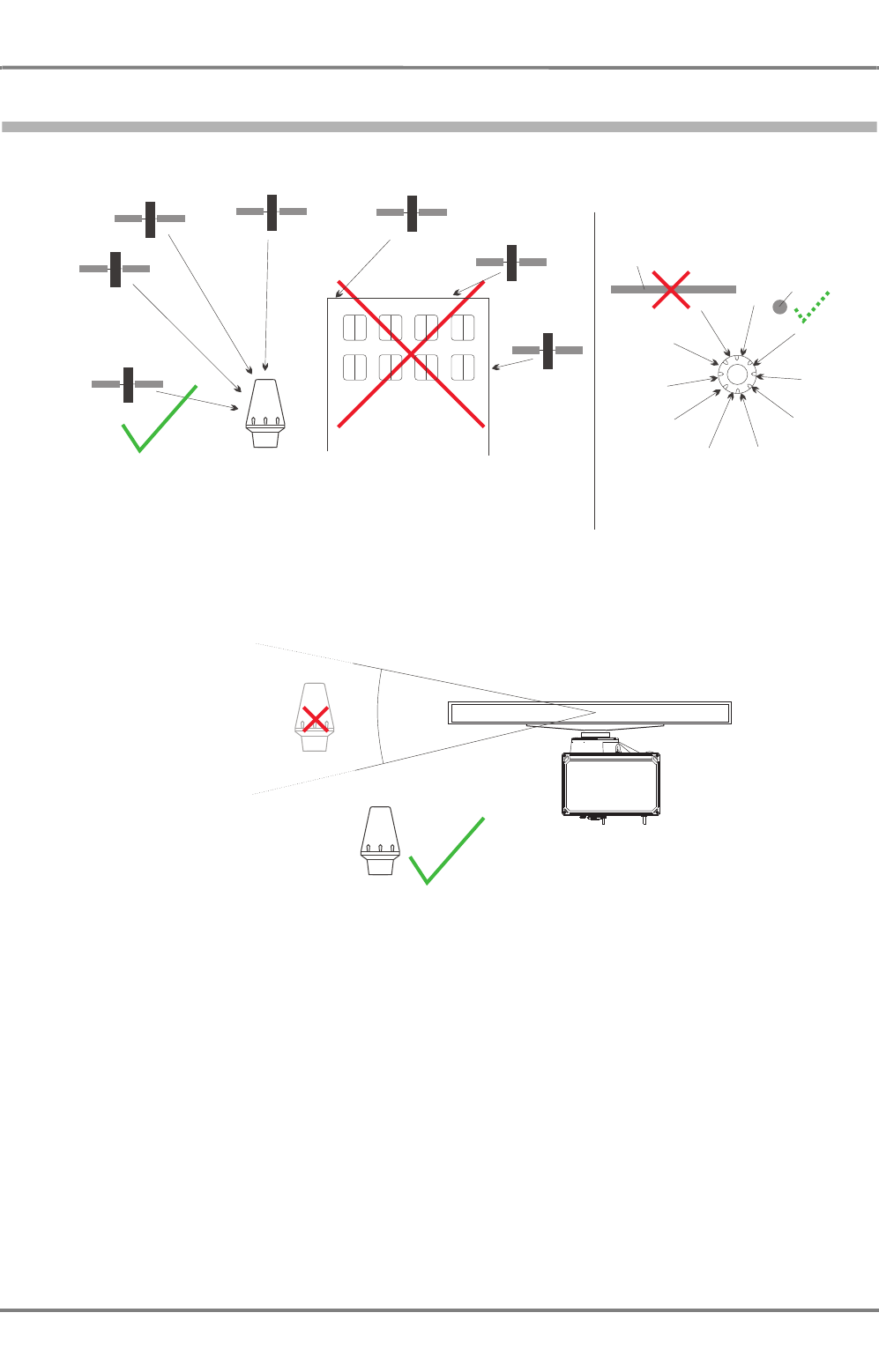
3.2.3.2
Recommendations Concerning the Installation of the GPS Antenna
Fig. 3-4 Positioning of the GPS Antenna
Fig. 3-5 Minimum distances for the GPS Antenna from a Radar Scanner
The GPS antenna should be installed where it has a clear "view" of the sky. The objective is that it should
"see" the horizon freely through 360° with a vertical observation sector of 5...90° above the horizon. Small
diameter obstructions, such as masts and booms, do not seriously degrade signal reception, but such
objects should not eclipse more than a few degrees of any given bearing.
Locate the antenna at least 3 m away from and out of the transmitting beam of high-power transmitters
(S-Band radar and/or Inmarsat systems). This includes the ship’s own AIS VHF antenna.
GPS
Antenna
GPS
Antenna
GPS
Satellites
GPS
Satellites
360° view
Mast, boom
with small diameter
Mast, boom
with small diameter
Side view Top view
Superstructures,
e.g. deck house,
funnel
Superstructures,
e.g. deck house,
funnel
Superstructures,
e.g. deck house,
funnel,
Superstructures,
e.g. deck house,
funnel,
z_ue_043.eps
25°
GPS
Antenna
GPS
Antenna
SAM
z_ue_042.eps

AIS 3410, Electronics Unit
ED3047G842 / 01 (2009-08)
Technical Manual
3 Installation Recommendations
3.2 Specific Recommendations
t_ue_e03.fm / 27.08.09
28
3.2.4 Recommendations Concerning Redundancy
If possible, the Electronics Unit should be supplied with the ship’s sensor data from two different sources,
e.g. in a dual installation with RADARPILOT 1000 or 1100 the AIS can be supplied with sensor data from
both radars.
NACOS xx-3 only:
If two Ship’s Interfaces are existing because of redundancy purposes, the ship’s sensor output(s) of both
Ship’s Interfaces must be connected to the AIS Electronics Unit.
3.2.5 Recommendations Concerning the Connection of a (D)GPS to AIS 3410
For an AIS stand-alone installation with the connection of an external (D)GPS position sensor, the
following prerequisites must be fulfilled:
NMEA Version
NMEA version 2.01 edition 04/1994 or newer is required. In addition to this, the optional checksum is
required. The AIS requires status information to check the data integrity.
All NMEA versions lower than 2.01 are not allowed for the use with AIS. To verify, that the NMEA version
is 2.01 or higher, check the settings of the GPS sensor.
Data Telegrams
For all NMEA versions lower than 2.3 the GGA message must be transmitted. Only the GGA message
transmits the information, that the differential mode is activated. This is set at the GPS receiver. If this
telegram is not transmitted, it is not indicated that a DGPS is connected to the AIS.
To check, that a DGPS is connected correctly, check the AIS State Menu of the connected RADAR-
PILOT/CHARTRADAR.
3.2.6 Emergency Power Source
It is recommended that an emergency power source such as an uninterruptible power supply is used. See
Section 7 for information about the power consumption of the Electronics Unit.
3.2.7 Pilot Port, Connector/Cable Kits
The regulations for AIS systems prescribe a connector for the Pilot Port. This connector is standardized.
The following kits are available:
Kit Consisting of Order No.
Panel mounting Connector 9 pole (male), for panel mounting with 3 m cable
(NG3030G014) 300006056
Free hanging Connector 9 pole "free hanging" (male) with 10 m cable
(NG3030G013) 300006049

AIS 3410, Electronics Unit
ED3047G842 / 01 (2009-08)
Technical Manual
3 Installation Recommendations
3.2 Specific Recommendations
t_ue_e03.fm / 27.08.09
29
3.2.8 Recommendations Concerning AIS Stand-alone with Radar 9xxx / NACOS xx-2/-3
An AIS 3410 can be used with an existing Radar 9xxx installation without any additional software update
if the following prerequisites are fulfilled:
- All necessary ship’s sensors are connected additionally to the AIS Electronics Unit. The sensors
must be connected directly (a Gyro Converter Unit may be necessary). It is not permissible to
connect the output channels of the Ship’s Interface to the AIS Electronics Unit.
or
-Only the heading information may be derived from the Ship’s Interface. For this purpose, at least
one free output channel must be available and the system software must be 039 (or higher) for
NACOS xx-2 or 071 (or higher) for NACOS xx-3.
If the AIS derives it’s position sensor data from the Ship’s Interface, a software update for the complete
navigation system must be performed. The software version must be 096 or higher. Older versions do
not comply to IEC 61162-1 edition 3, 04/2007 (NMEA0183 version 3.01). In these versions source and
status of the position data is not indicated. Such versions must not be used with an AIS.
If the AIS is installed in combination with a MULTIPILOT 91x0 or a CHARTPILOT 9320/9330, the
complete navigation system has to be updated to software version 097A or higher.
NOTE:
CHARTPILOTs with a software version 4.0 or newer require an 8-channel Ship’s Interface.
3.2.9 Recommendations Concerning the Connection to a Radar 1000/1100 Series System
In a single installation, an Analog Interface must be existing to connect the AIS system. In dual or multiple
installations with two Analog Interfaces, the AIS must be connected as follows:
Radar software version ≤ 2.6: Analog Interface No. 1 (usually at Indicator No. 1)
Radar software version ≥ 2.6.1: Analog Interface No. 2 (usually at Indicator No. 2)
The AIS Electronics Unit must not be connected to both Analog Interfaces!
At a radar with software version 3.0 or newer or a MULTIPILOT 1000, the AIS can be connected also by
means of the Ethernet LAN. In this case, an Analog Interface is not necessary (if it is not needed for an
analog gyro).
3.2.10Recommendations Concerning the Connection to a Radar 1100 Series System
In a single installation, an Analog Interface must be existing to connect the AIS system. In dual or multiple
installations with two Analog Interfaces, the AIS must be connected to Analog Interface No. 2 (usually at
Indicator No. 2).
The AIS Electronics Unit must not be connected to both Analog Interfaces!
The AIS can be connected also by means of the Ethernet LAN. In this case, an Analog Interface is not
necessary (if it is not needed for an analog gyro).

AIS 3410, Electronics Unit
ED3047G842 / 01 (2009-08)
Technical Manual
3 Installation Recommendations
3.2 Specific Recommendations
t_ue_e03.fm / 27.08.09
30
AIS 3410, Electronics Unit
ED3047G842 / 01 (2009-08)
Technical Manual
4 Functional Description
4.1 Block Diagram
t_ue_e04.fm / 27.08.09
31
4 Functional Description
The AIS system consists of the following components:
- AIS 3410 Electronics Unit
- GPS antenna 1330FW
- VHF antenna CXL 2-1
The functionality is described in Section 4.1 by means of the block diagram (Figure 4-3).
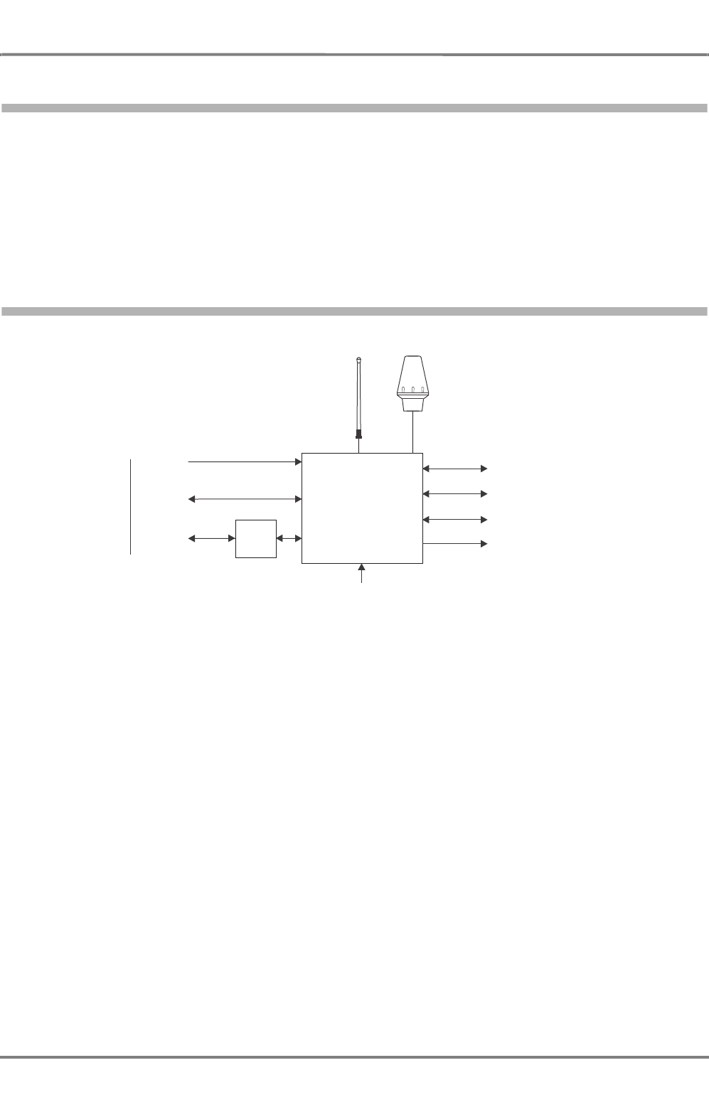
4.1 Block Diagram
Fig. 4-1 Block diagram of the AIS System
The AIS Electronics Unit contains a VHF radio, a GPS receiver and a Mainboard with the interfaces. The
AIS Electronics Unit has three inputs for the essential ship’s sensor data such as position, speed and
heading. These data are supplied by means of the navigation system such, as a RADARPILOT 1000/
1100. The AIS communicates with the navigation system via the primary display port and/or the Ethernet
LAN. In this way the AIS is supplied with additional data such as the ship’s data, administration data and
configuration data.
The ship’s data, the ship’s sensor data and the position data (from external or internal GPS receiver) are
transmitted via VHF.
In the opposite direction, the corresponding data of other ships equipped with AIS systems are received
by means of the VHF receiver.These data are processed and sent to the navigation system via the
primary display port or the Ethernet LAN.
The functions of the pilot port correspond to the functions of the primary display port, but the pilot port
must be made accessible for pilots on the ship’s bridge. It must not be used for other purposes.
The DSC Receiver receives messages from external stations such as VTS. By means of the DSC
messages, specific settings such as a change of the VHF channels can be controlled.
z_ue_015.pdf
VHF
Antenna
Radar /
NACOS system
Pilot Port
Long Range Port
Internal Position Sensor
Alarm relay contacts
Ship's
sensor data
Primary
Display Port
(PDP)
Transfers the
same data as
the PDP
AIS
Electronics Unit
GPS
Antenna
3 x RS422 RS422
RS422
RS422
RS422
and/or
LAN
24 VDC
Media
Converter
RJ-45
BNC
AIS 3410, Electronics Unit
ED3047G842 / 01 (2009-08)
Technical Manual
4 Functional Description
4.2 Termination
t_ue_e04.fm / 27.08.09
32
The VHF transmitter/receiver has a limited range. By means of the connection of a long range commu-
nication system (such as a satellite communication system) to the long range port, this limitation can be
eliminated. In this way, the AIS can be called to send the ship’s data. The requested data are sent via
the long range port and the long range communication system to the questioner. The operator can decide
whether a long range request is answered or not.
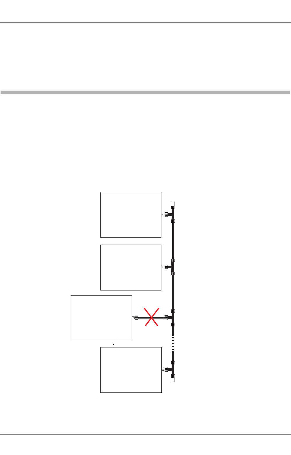
4.2 Termination
The wiring must be done in accordance with Figure 4-2 with 50 Ω coaxial cable (for example inside the
enclosures, RG 58, for ship’s cabling RG 213 / U, see cabling diagrams). The network is a 10 Mbit
network.
The BNC-T plugs must be connected directly into the Ethernet Module. It is not admissible to connect the
T-plug and the network adapter by means of a coaxial cable.
Proper termination with a 50 Ω BNC termination plug at both ends of the Ethernet line is very important.
It is not permissible to use cable with a characteristic impedance different from 50 Ω.
If no cable is connected to the Ethernet connector, it must also be terminated.
Fig. 4-2 Principle of wiring for Ethernet LAN
T
T
z_ue_11.eps
AIS 3410, Electronics Unit
ED3047G842 / 01 (2009-08)
Technical Manual
4 Functional Description
4.3 Description of the Components
t_ue_e04.fm / 27.08.09
33
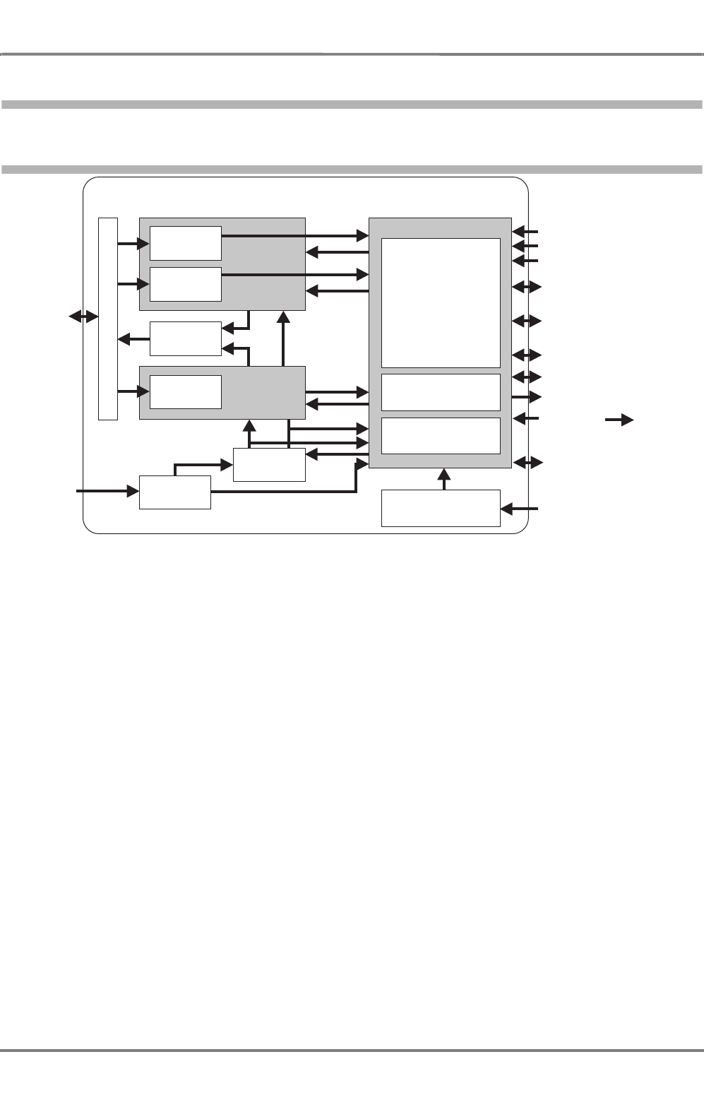
4.3 Description of the Components
4.3.1 AIS 3410 Electronics Unit
Fig. 4-3 Block diagram of the Electronics Unit
The diagram Figure 4-3 shows the internal structure of the AIS Electronics Unit with the following parts:
VHF Radio
• VHF Receiver:
• AIS Channel A
• AIS Channel B
• DSC Channel 70
• VHF Transmitter:
• AIS Channel A
• AIS Channel B
• DSC Channel 70
GPS
• 16-channel GPS chip
Motherboard and Peripheral Components
• Motherboard pcb
• Processors for the digital signal processing
• 3 interfaces IEC 61162-1/2 for ship’s sensor data input
• Long range port IEC 61162-2
• Primary display port IEC 61162-2 and pilot port IEC 61162-2
• Ethernet interface
• Built-in Integrity Test (BIIT)
• Power supply (input 24 VDC -20%, +20%)
Electronics Unit Interfaces
and Displays
Antennas
Mainboard
AIS
DSC
BIIT
Power
Supply
AIS - A
Receiver
AIS - B
Receiver
VHF antenna
Sensor Input Channels
RS422, IEC 61162 -1/2
(4800/38400 Baud)
Long Range Port, RS422
IEC 61162 -2 (38400 Baud)
Primary Display Port, RS422
IEC 61162 -2 (38400 Baud)
Pilot Port, RS422
IEC 61162 -2 (38400 Baud)
Ethernet Module
24 VDC
Internal Position Sensor
GPS antenna
Transmitter
VHF Antenna Module
DSC
Clock
GPS
Service Port, RS232
RTCM DataRS422,
IEC 61162 -1
(4800 Baud)
z_ue_018.pdf
AIS 3410, Electronics Unit
ED3047G842 / 01 (2009-08)
Technical Manual
4 Functional Description
4.3 Description of the Components
t_ue_e04.fm / 27.08.09
34
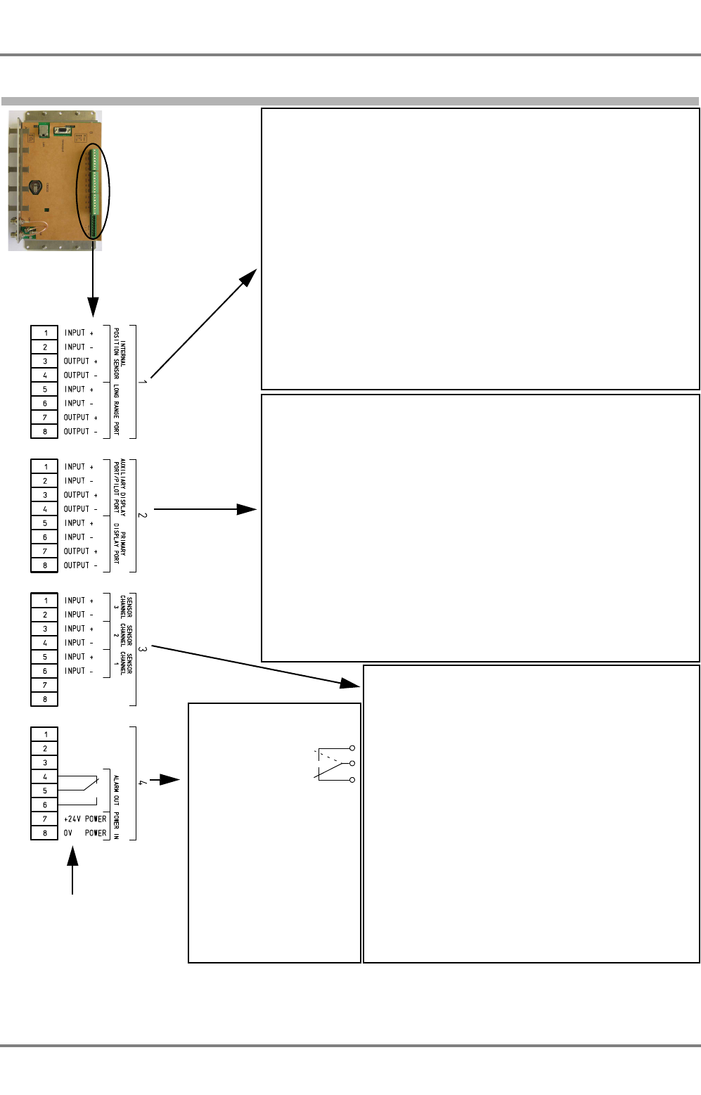
4.3.1.1
Interfaces
Fig. 4-4 Interfaces of the AIS 3410 Electronics Unit
z_ue_014.pdf
Connector 4
Alarm Relay
4 Contact, break
5 Contact, center
6 Contact, make
Relay on position:
A = Alarm active or mains off
B = No alarm and mains on
Power Supply Input
7 +24 V
80 V
A
B
4
5
6
Connector 3
Sensor Input Channels, RS422, IEC 61162 -1/2 (4800/
38400 Baud)
for ship’s sensors
1 Channel 3 +
2 Channel 3 -
3 Channel 2 +
4 Channel 2 -
5 Channel 1 +
6 Channel 1 -
The AIS can be supplied with the following sensor data, corre-
sponding to IEC 61162-1/2 (bold type = required default telegrams):
-
Reference datum (
DTM
, NACOS xx-4, RADARPILOT 1000 only)
- Positioning system (GNS, GLL, RMC)
- Speed over ground (VBW, VTG, RMC)
- Course over ground (RMC, VTG)
- Heading (HDT)
- RAIM indicator (GBS)
- Rate of turn (ROT)
Connector 1
Input of RTCM SC104 correction data
RS422, IEC61162-1 (4800 Baud)
1 Input + / RxD +
2 Input - / RxD -
Output of the messages corresponding to (IEC 61108-1) from internal position
sensors, RS422, IEC61192-1 (4800 Baud):
DTM (datum reference); GGA (GPS fix data); GNS (GNSS fix data); GLL (geographic
position, latitude/longitude); RMC (recommended minimum specific GNSS data); VTG
(course over ground and speed over ground); GBS (RAIM data)
3 Output + / TxD +
4 Output - /TxD -
Long Range Port, RS422, IEC 61162 -2 (38400 Baud)
5 Input + / RxD +
6 Input - / RxD -
7 Output + / TxD +
8 Output - / TxD -
Connection to a long range communication system. Requests by the messages LRI and
LRF are answered with LR1, LR2 and/or LR3.
The wires can be connected
to the connectors directly by
means of screw terminals.
Connector 2
Pilot Port, RS422, IEC 61162 -2 (38400 Baud)
1 Input + / RxD +
2 Input - / RxD -
3 Output + / TxD +
4 Output - / TxD -
See Primary Display Port.
This port must not be used for the system. It must be accessible for the pilot.
Primary Display Port, RS422, IEC 61162 -2 (38400 Baud)
5 Input + / RxD +
6 Input - / RxD -
7 Output + / TxD +
8 Output - / TxD -
Output of VDM messages (received by VHF) and VDO messages (sent by VHF).
The static ship’s data such as ship’s name, callsign and destination are input by means
of the VSD and SSD messages. See IEC 61993-2 for valid messages.
This port is connected to the SAM Electronics system, for example.
Additionally, the sensor data (VDO message) are sent with a repetition rate of 1 Hz.
AIS 3410, Electronics Unit
ED3047G842 / 01 (2009-08)
Technical Manual
4 Functional Description
4.3 Description of the Components
t_ue_e04.fm / 27.08.09
35
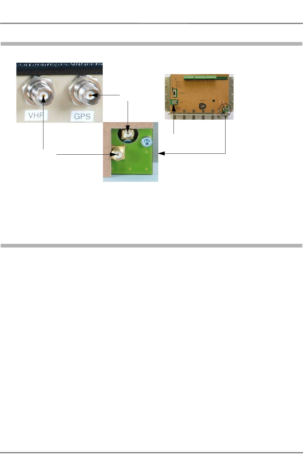
4.3.1.2
Internal Connectors
Fig. 4-5 Internal connectors
For retrofit of older housings (UAIS DEBEG 3400) refer to Section 2.9.
Installation of the Media Converter refer to Section 2.10.
4.3.1.3
Supported Sensor Input Sentences
Prerequisites:
NMEA Version
2.01 edition 04/1994 (corresponds to the first edition of IEC 61162) or higher is required. In
addition the optional checksum is required. AIS requires status information to check the data
integrity.
All NMEA versions below 2.01 are not allowed for the use with AIS.
Data Telegrams
For all NMEA versions below 3.01 (corresponds to IEC 61162-1 edition 3/2007) the GGA
message must be transmitted.
Only the GGA message transmits the information that differential mode is activated. This is set
at the GPS receiver.
If this telegram is not transmitted, it is not indicated that a DGPS is connected to the AIS.
VHF
GPS
LAN (RJ-45)

AIS 3410, Electronics Unit
ED3047G842 / 01 (2009-08)
Technical Manual
4 Functional Description
4.3 Description of the Components
t_ue_e04.fm / 27.08.09
36
Input sentences in compliance with IEC 61162-1/-2
NOTE:
If the AIS Electronics Unit receives the ship’s sensor data from Ship’s Interface, the output interfaces of
the Ship’s Interface must be configured as follows:
- Select "IEC 61162-1 edition 3/2007 (NMEA 3.01)" as driver
- Set a repetition interval of 1 s for the following telegrams: GLL, VTG, HDT, ROT, VBW
Data Required Sentence
(Identifier and Description)
Optional Sentence
(Identifier and Description)
Reference Datum DTM (Datum reference)
Positioning System:
- Time of Position
- Latitude/Longitude
- Position accuracy
- GNS (GNSS fix data)
- GLL (Geographic position latitude/
longitude)
- RMC (Recommended minimum
specific GNSS data)
Speed over Ground (SOG) - VBW (Dual ground/water speed) - VTG (Course over ground and ground
speed)
- RMC (Recommended minimum
specific GNSS data)
Course over Ground (COG) - RMC (Recommended minimum
specific GNSS data)
- VTG (Course over ground and ground
speed)
Heading - HDT (Heading, true)
RAIM indicator - GBS (GNSS satellite fault detection)
Rate of Turn (ROT) - ROT (Rate of turn)

AIS 3410, Electronics Unit
ED3047G842 / 01 (2009-08)
Technical Manual
4 Functional Description
4.3 Description of the Components
t_ue_e04.fm / 27.08.09
37
4.3.1.4
Supported Sentences for the AIS Primary Display Port and the Pilot Port
Input
Input sentences in compliance with IEC 61162-1/-2
Data Sentence Identifier/Description
Normal Access - Parameter Entry
Voyage information:
- Vessel type and cargo category
- Navigational status
- Draught, max. actual static
- Destination
- ETA date and time
- Regional application flags
VSD (Voyage static data)
Station information:
- Vessel name
- Call sign
- Antenna location
- length and beam
SSD (Ship static data)
Initiate VHF Data Link Broadcasts
Safety messages ABM (Addressed binary message)
BBM (Broadcast binary message)
Binary messages ABM (Addressed binary message)
BBM (Broadcast binary message)
Interrogation message AIR (AIS interrogation information)
AIS Equipment - Parameter Entry
AIS VHF channel selection
AIS VHF power setting
AIS VHF channel bandwidth
Transmit/Receive mode control
ACA (AIS channel assignment message)
ACA (AIS channel assignment message)
ACA (AIS channel assignment message)
ACA (AIS channel assignment message)
BIIT Input
Alarm/Indication acknowledgement ACK (Acknowledgement message)
LR acknowledge
Manual LR acknowledge LRF (Long range function)
Proprietary Sentences
AIS Electronics Unit configuration
-MMSI
-IMO number
- Other AIS equipment controls
AISCFG (AIS configuration)
AIS serial input/output configuration AISSIO (AIS serial input/output)
AIS transmitter on/off, acknowledged by AISTXD from the
Electronics Unit
AISTXD (AIS transmitter status)
AIS alive message (every 20 s) AISALV (AIS alive)
Transversal and longitudinal offset of the internal AIS position
sensor relative to the ship’s system position
AISPOF (AIS offset, relative to system position)
Any telegram which is sent by long range function must be
acknowledged by means of AISLRA
AISLRA (AIS long range acknowledgement)
Queries
-Query ACA
- Query PSAEAISTXD
- Query PSAEAISLFS
- Query PSAEAISVER
Q
Query for ACA data
Query for transmitter status
Query for Electronics Unit log file
Query for firmware version
AIS 3410, Electronics Unit
ED3047G842 / 01 (2009-08)
Technical Manual
4 Functional Description
4.3 Description of the Components
t_ue_e04.fm / 27.08.09
38
Output
Output sentences in compliance with IEC 61162-1/-2
4.3.1.5
Supported Sentences for the Long Range Port
Input
Input sentences in compliance with IEC 61162-1/-2, edition 3, 04/2007 (NMEA0183 version 3.01)
Data Sentence Identifier/Description
Prepared by AIS Unit
Notification that a session initiated by the messages ABM,
BBM, AIR is terminated
ABK (Acknowledgement message)
AIS own-ship broadcast data (all transmissions available) VDO (VHF data link own-vessel message)
Channel management data ACA (AIS channel assignment message (using
query mechanism)
Received on VHF Data Link by AIS Unit
All VDL AIS messages received
Broadcast or addressed to own station
VDM (VHF data link message)
Received on LR Communication System
LR interrogation message received LRI (Long range interrogation) and LRF (Long
range function identification)
Proprietary Sentences
AIS Electronics Unit power on AISPWR (AIS power)
Log file data AISLFS (AIS log file send)
Acknowledge to AIS transmitter status on/off AISTXD (acknowledge to AIS transmitter status)
Report on a long range interrogation to the MKD AISLRF (AIS long range function request)
AIS firmware version AISVER (AIS version)
Data Sentence Identifier/Description
Long range interrogation:
- Type of request
- Geographic area request
- AIS unit request
LRI (Long range interrogation)
Long range function identification, Requester MMSI and Name
Request for:
- Ship’s name, call sign, IMO number
- Date and time of message composition
- Position
- Course over ground
- Speed over ground
- Destination and ETA
- Draught
-Ship/Cargo
- Ship’s length, breadth and type
- Number of persons on board
LRF (Long range function identification)

AIS 3410, Electronics Unit
ED3047G842 / 01 (2009-08)
Technical Manual
4 Functional Description
4.3 Description of the Components
t_ue_e04.fm / 27.08.09
39
Output
Output sentences in compliance with IEC 61162-1/-2
Data Sentence Identifier/Description
Long range function identification, MMSI and Name
- Ship’s name, call sign, IMO number
- Date and time of message composition
- Position
- Course over ground
- Speed over ground
- Destination and ETA
- Draught
-Ship/Cargo
- Ship’s length, breadth and type
- Number of persons on board
LRF (Long range function identification)
MMSI of responder
MMSI of requester
Ship’s name
Ship’s call sign
IMO number
LR1 (Long range response, line 1)
MMSI of responder
Date and time of message composition
Position
Course over ground
Speed over ground
LR2 (Long range response, line 2)
MMSI of responder
Destination and ETA
Draught
Ship/Cargo
Ship’s length, breadth and type
Number of persons on board
LR3 (Long range response, line 3)

AIS 3410, Electronics Unit
ED3047G842 / 01 (2009-08)
Technical Manual
4 Functional Description
4.3 Description of the Components
t_ue_e04.fm / 27.08.09
40
4.3.1.6
Supported Sentences for the Internal Position Sensor
Output
Output sentences in compliance to IEC 61162-1, edition 3, 04/2007 (NMEA0183 version 3.01)
Data Sentence Identifier/Description
Datum reference
- Local datum (e.g. WG84)
- Local datum subdivision code (not used)
- Lat offset, min, N/S (not used)
- Lon offset, min, E/W (not used)
- Altitude offset, m (not used)
- Reference datum (e.g. WG84)
DTM (Datum reference)
Global positioning system (GPS) fix data
- UTC (hhmmss.ss)
- Latitude N/S (data and "N" or "S" or empty fields)
- Longitude E/W (data and "E" or "W" or empty fields)
- GPS quality ( 0=fix not available
1=GPS SPS mode
2=Differential mode
3=GPS PSS mode
4=Real Time Kinematic
5=Float RTK
6=Estimated mode
7=Manual input mode
8=Simulator mode)
- Number of satellites (00...12)
- Horizontal dilution (x.x data or empty field)
- Antenna altitude (x.x data or empty field)
- Units of antenna altitude (M or empty field)
- Geoidal separation (x.x data or empty field)
- Units of Geoidal separation (M or empty field)
- Age of diff. GPS data (x.x data or empty field)
- Diff. reference station (xxxx data or empty field)
GGA (Global positioning system)
Geographic position - latitude/longitude
- Latitude N/S (data and "N" or "S" or empty fields)
- Longitude E/W (data and "E" or "W" or empty fields)
- UTC of position (hhmmss.ss)
- Status ("V" or "A")
- Mode indicator ( A=Autonomous mode
D=Differential mode
E=Estimated mode
M=Manual input mode
S=Simulator mode
N=Data not valid
GLL (Geographic position - latitude/longitude)
Global positioning system
- UTC (hhmmss.ss)
- Latitude N/S (data and "N" or "S" or empty fields)
- Longitude E/W (data and "E" or "W" or empty fields)
- Mode indicator ( N=No fix
A=Autonomous
D=Differential
P=Precise
R=Real Time Kinematic
F=Float RTK
E=Estimated
M=Manual input
S=Simulator mode
- Number of satellites (00...99)
- Horizontal dilution (x.x data or empty field)
- Antenna altitude (x.x data or empty field)
- Geoidal separation (x.x data or empty field)
- Age of diff. GPS data (x.x data or empty field)
- Diff. reference station (x.x data or empty field)
GNS (Global positioning system)

AIS 3410, Electronics Unit
ED3047G842 / 01 (2009-08)
Technical Manual
4 Functional Description
4.3 Description of the Components
t_ue_e04.fm / 27.08.09
41
The AIS 3410 is equipped with a 16 channel GPS receiver and provides position data according to IEC
61162, edition 3, 04/2007 (NMEA0183 version 3.01), so that it is suitable for the use as a position sensor.
In areas where the VTS stations provide differential correction data via VHF link the AIS 3410 switches
automatically into DGPS mode.
4.3.1.7
IEC 61162 -1/-2 Interfaces, Electrical Characteristics
The interfaces comply with IEC 61162-1, edition 3, 04/2007 (NMEA0183 version 3.01) and IEC 61162-
2:1998.
The designation "-" in this manual corresponds to the designation "Line A" of IEC 61162 -1/-2.
The designation "+" in this manual corresponds to the designation "Line B" of IEC 61162 -1/-2.
Output Current and Input Load
Maximum output current: 25 mA at 3.0 V
Listener, receiver load: 0.8 mA at 0.3 V differential voltage
1.25 mA at 2.0 V differential voltage
Recommended minimum specific GNSS data
- UTC (hhmmss.ss)
- Status ("V" or "A")
- Latitude, N/S (IIII.II,a)
- Longitude, E/W (YYYYY.YY,a)
- Speed over ground, knots (x.x)
- Course over ground, degrees true (x.x)
- Date; dd/mm/yy (xxxxxx)
- Magnetic variation, degrees, E/W (data and "E" or "W"
or empty fields
- Mode indicator ( A=Autonomous mode
D=Differential mode
E=Estimated mode
M=Manual input mode
S=Simulator mode
N=Data not valid
RMC (Recommended minimum specific GNSS
data)
Course over ground and ground speed
- Course over ground, degrees true (x.x data and "T"
or empty fields)
- Course over ground, degrees magnetic (x.x data and "M"
or empty fields)
- Speed over ground, knots (x.x data and "N" or empty fields)
- Speed over ground, km/h (x.x data and "K" or empty fields)
- Mode indicator ( A=Autonomous mode
D=Differential mode
E=Estimated mode
M=Manual input mode
S=Simulator mode
N=Data not valid
VTG (Course over ground and ground speed)
Time and date
- UTC (hhmmss.ss)
- Day, 01 to 31 (xx)
- Month, 01 to 12 (xx)
- Year (xxxx)
- Local zone hours (xx data or empty field)
- Local zone minutes (xx data or empty field)
ZDA (Time and date)
Data Sentence Identifier/Description
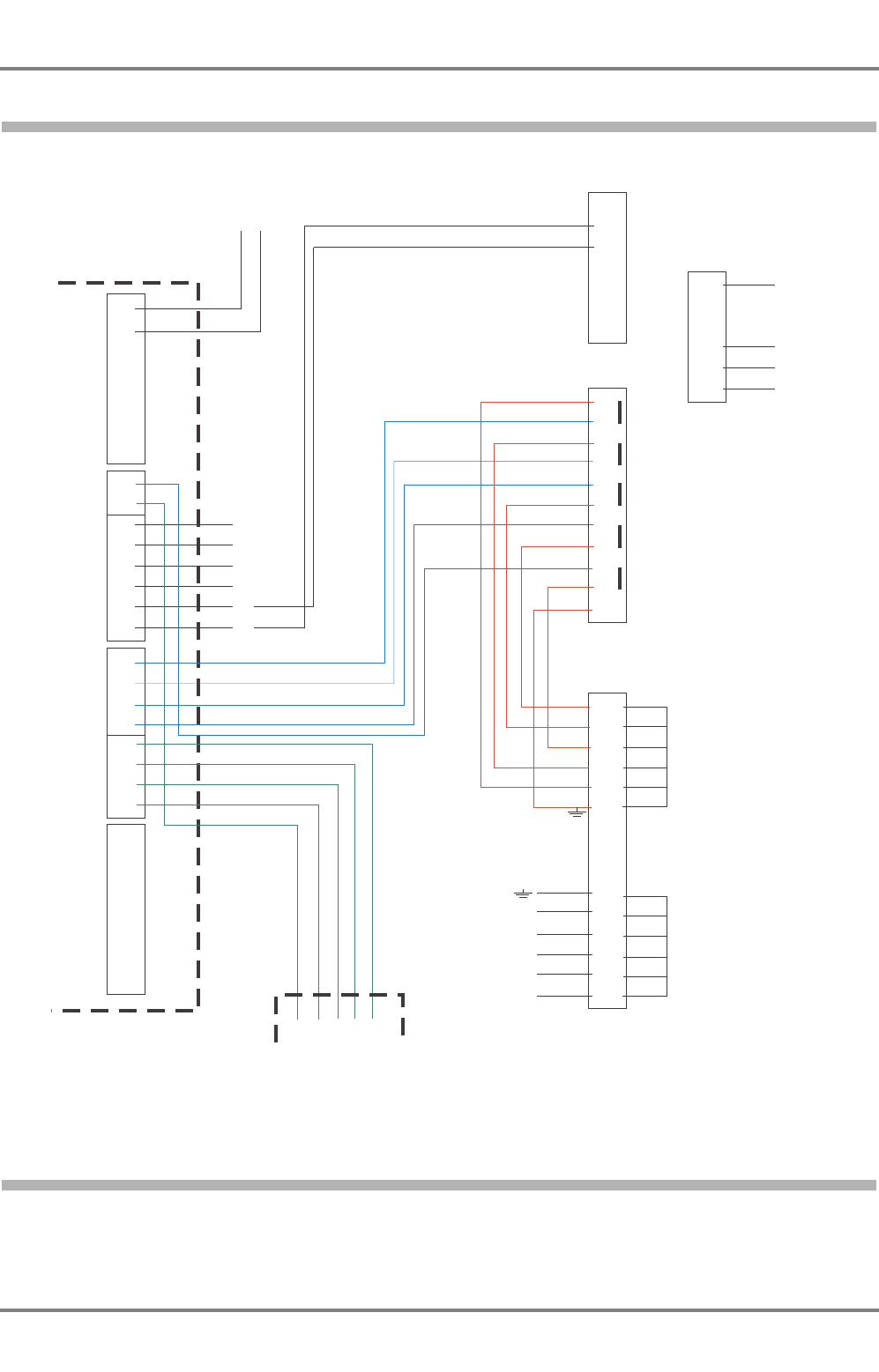
AIS 3410, Electronics Unit
ED3047G842 / 01 (2009-08)
Technical Manual
4 Functional Description
4.3 Description of the Components
t_ue_e04.fm / 27.08.09
42
4.3.1.8
Example for the Interconnection
Fig. 4-6 AIS and Gyro Interface 9401
4.3.2 VHF Antenna
The VHF antenna CXL 2-1 is a ½λ coaxial, broad band antenna with 50 Ω impedance. For the technical
data see Section 7.2.2, for installation instructions see Section 3.
8
7
6
5
4
3
2
1
8
7
6
5
4
3
2
1
8
7
6
5
4
3
2
1
8
7
6
5
4
3
2
1
1
2
3
4J1
AIS Electronics Unit
Gyro Interface 4901
Pilot Plug
+24 V0V
BN
GY
PK
WH
WH
GN
GN
YE
YE
BN
GY
PK
S3
+ 24 V
0V
Alarm break
Alarm center
Alarm make
R
S
T
Common
695
4
1
S2
tupnI rosneSrPmiD.lpsiP.. toliPoPtr
S1
-
-
-
+
+
+
8
9
10
11
7
6
5
4
3
2
1
8
12
9
13
10
14
11
15
7
6
5
4
3
2
1
TB
Te r m i n als
yard supply
TB
16
15
14
13
12
11
10
25
24
23
22
21
20
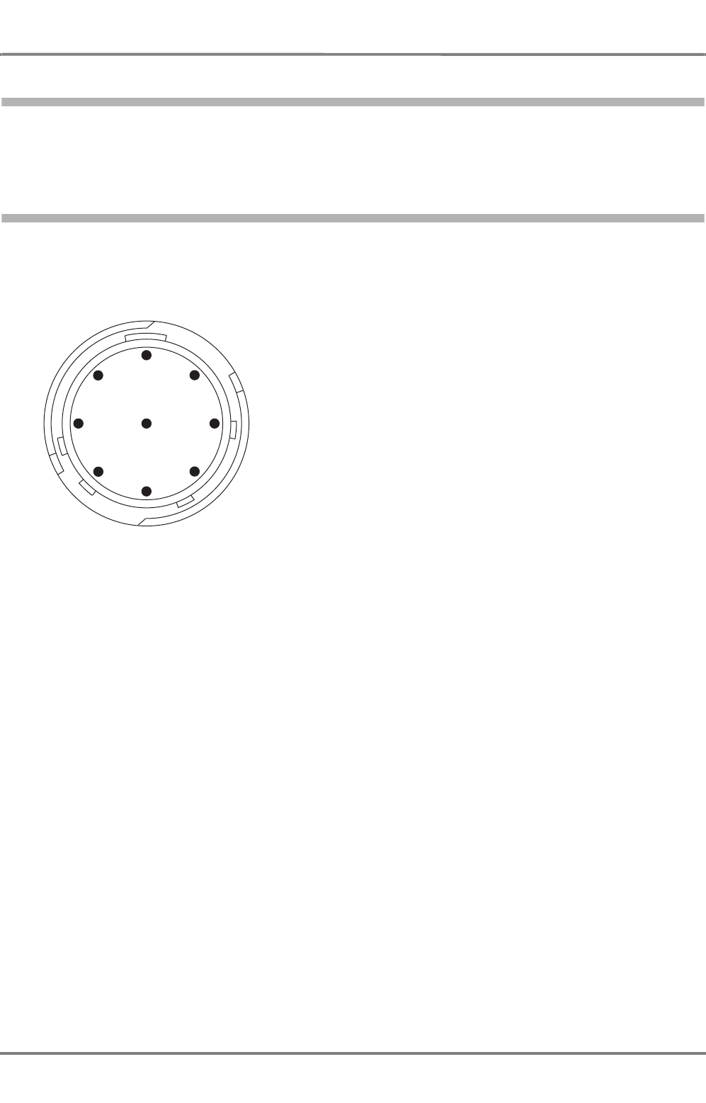
AIS 3410, Electronics Unit
ED3047G842 / 01 (2009-08)
Technical Manual
4 Functional Description
4.3 Description of the Components
t_ue_e04.fm / 27.08.09
43
4.3.3 GPS Antenna
The GPS antenna 1330 is a GPS L1 antenna for a frequency of 1575.42 ±10 MHz with an integrated
amplifier. For the technical data see Section 7.2.3, for installation instructions see Section 3.
4.3.4 Pilot Port
The Pilot Port must be connected as prescribed in the regulations. The connector/cable kits are described
in Section 3.2.7 on page 28. The wires of the cable are marked and must be connected to connector 2,
terminal 1...4.
Fig. 4-7 Pilot Port, connector assignment, front view (pins)
For passages of the Panama Channel a 125 V AC supply (NEMA 5-15) must be available for the pilot.
For ships with 230 V mains, the transformer 271257903 can be ordered from SAM Electronics.
z_ue_030.eps
1
3
2
4
5
6
78
9
Pin Function / Color of wire / Connection at AIS Electronics Unit
1 TxD - (Output -) / white / Connector 2, terminal 4
2 not connected
3 not connected
4 TxD + (Output +) / brown / Connector 2, terminal 3
5 RxD - (Input -) / red / Connector 2, terminal 2
6 RxD + (Input +) / blue / Connector 2, terminal 1
7 not connected
8 not connected
9 GND/shield must be connected to the Electronics Unit housing
and GND terminal
Depending on the position of the pilot plug, the cable must be connected via an additional
terminal row and ship’s cable as described in the cabling documents.
male

AIS 3410, Electronics Unit
ED3047G842 / 01 (2009-08)
Technical Manual
4 Functional Description
4.3 Description of the Components
t_ue_e04.fm / 27.08.09
44
AIS 3410, Electronics Unit
ED3047G842 / 01 (2009-08)
Technical Manual
5 Setting-to-Work/Configuration
5.1 Setting-to-Work
t_ue_e05.fm / 27.08.09
45
5 Setting-to-Work/Configuration
5.1 Setting-to-Work
1. The AIS Electronics Unit and the antennas must be installed as described in Section 3 (
Installation
Recommendations
). For information about the dimensions see Section 10 (
Outline Drawings
).
2. The cabling and connection must be performed corresponding to the Cabling Documents in Section
9.
3. Depending on the system in which the AIS has to be integrated, the configuration has to be
performed as described in Section 5.3.
5.2 Software Versions
The software versions can be downloaded as packages with the software components for all units of the
AIS system. For further information about the download and the update see Section 6.3 on page 54.
5.3 Configuration
No adjustments have to be performed on the antennas. These components are ready for use.
The AIS Electronics Unit must be parameterized via a connected RADARPILOT 1000/1100, CHART-
PILOT 9320/30, MULTIPILOT 1000/1100.
For information in detail, see the corresponding Technical Manuals and the Online Help of these systems.
The following descriptions are an aid for the configuration of the AIS.
NOTE:
Valid for NACOS xx-3 Systems only:
The AIS Electronics Unit is connected to the Ship’s Interface. The output interfaces of the
Ship’s Interface must be configured as follows:
- Select "IEC 61162-1 edition 2/2000 (NMEA 2.3)" as driver
- Set a repetition interval of 1 s for the following telegrams:
-GLL
-VTG
-HDT
-ROT
- VBW (if bottom-track log is available)
NOTE:
The system from which the AIS Electronics Unit has been configured and the AIS itself must be restarted
after any change in the configuration. Otherwise modifications may have no effect.
5.3.1 Configuration with RADARPILOT/CHARTRADAR/MULTIPILOT 1000/1100 - NACOS xx-4/5 Systems
It is necessary to configure the radar and the interfaces. For information in detail see the Technical
Manual of the RADARPILOT/CHARTRADAR 1000/1100 and MULTIPILOT 1000/1100.
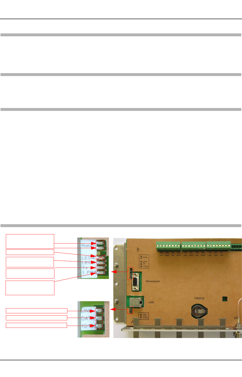
AIS 3410, Electronics Unit
ED3047G842 / 01 (2009-08)
Technical Manual
5 Setting-to-Work/Configuration
5.4 Testing
t_ue_e05.fm / 27.08.09
46
5.3.2 Configuration with CHARTPILOT 93xx in NACOS xx-3 Systems
It is necessary to configure the CHARTPILOT 93xx and the interfaces of the Ship’s Interface. For infor-
mation in detail see the Technical Manual of the CHARTPILOT 93xx.
5.3.3 Configuration with Radar 9xxx
It is necessary to configure the interfaces of the Ship’s Interface. For information in detail see the Service
Manual of the Radar 9xxx Electronics Unit.
5.4 Testing
The Electronics Unit has neither operating elements nor a display. Correct functioning cannot be made
visible directly.
To test the interfaces of the ship’s sensor inputs and the interface to the display unit (which can be the
RADARPILOT 1000/1100, CHARTPILOT 9330 or the MULTIPILOT 1000/1100), set the system in oper-
ation and select the own ship’s symbol. If the own ship AIS data are displayed, the interfaces are working
properly.
The VHF Transceiver can only be tested if a second AIS system is within the range of the Transceiver.
The signals of this AIS must be received and this second AIS must receive the signals of your own AIS.
The pilot port can be tested by means of a PC with a terminal software, a RS422/RS232 converter and
cable with the suitable connector. The connector consists of the following components which can be
purchased from most specialist dealers:
- Plug assembly, AMP part No. 206485-1
- Socket contact, AMP part No. 66569-3
- Cable clamp kit, AMP part No. 182928-1
5.5 LEDs for Ethernet LAN, Alarm, GPS and Telegram
Fig. 5-1 Status LEDs
Alarm relay LEDs:
red: active alarm
green: no active alarm
LED 4 has no function
Telegram sent to HF LED
:
blinks one time
GPS impulse LED:
1 sec on, 1 sec off, blinking
continously
LAN Status LEDs
Link established: shines yellow
Data Transfer: shines green
Data rate 10-100MBit/s: shines red
Telegram received by HF
LED: blinks one time
AIS 3410, Electronics Unit
ED3047G842 / 01 (2009-08)
Technical Manual
6 Repair/Maintenance
6.1 Trouble Shooting
t_ue_e07.fm / 27.08.09
47
6 Repair/Maintenance
GENERAL:
The jumper settings and switch settings on a replacement pcb must be
the same as on the defective pcb. The wire connections must be made
in exactly the same way. Exceptions are explained in this manual.
6.1 Trouble Shooting
6.1.1 Hints
In the case of problems during setting-to-work, the cabling should be checked again. All components
must be supplied with power.
- To get more information about the problem, read the system fault messages on the screen and refer
to Section 8 on page 63.
Watchdog
In various error conditions the internal watchdog of the system causes a reset. During the reset the
message "AIS offline" may be displayed (e.g. CHARTPILOT).
Problems after Software Update
If the Electronics Unit does not restart after a software update, the alarm AIS OFFLINE is displayed and
a repeat of the software update is not possible, the Disk On Module is in an undefined status and must
be exchanged. See Section 6.3.5 on page 57 for further information. This happens in rare cases, when
the supply voltage for the Electronics Unit has been interrupted during the software update.

AIS 3410, Electronics Unit
ED3047G842 / 01 (2009-08)
Technical Manual
6 Repair/Maintenance
6.1 Trouble Shooting
t_ue_e07.fm / 27.08.09
48
6.1.2 Fault Tree
Failure Description Possible Causes Service Measure Spare Part No.
Unusual behaviour of AIS
application
Software hung up Reset Electronics Unit -
Software failure caused e.g.
by external data telegrams Software update (can be downloaded
in LiveLink)
AIS Offline
Software hung up Reset electronics unit -
Power supply off Check power supply 271259234
Software failure caused e.g.
by external data telegrams Software update (can be downloaded
in LiveLink)
Internal fan broken
(only old housing)
Replace internal fan
(only old housing) 271178645
Media Converter defective Replace Media Converter 271259883
Electronics Module defective Replace Electronics Module 271259341
Analog Interface Radar 1000/
1100 broken Replace Analog Interface 300005388
Radar 9xxx AIS Interface
broken
Replace Radar 9xxx AIS
Interface 300005903
RS 422 Interface broken Replace RS422 interface 1877061
Internal Clock lost
GPS antenna defective Replace GPS antenna 271257889
Internal GPS antenna cable
broken
Replace internal GPS
antenna cable 271178666
GPS antenna connector
defective
Replace internal GPS
antenna cable 271178666
External GPS antenna cable
broken
Replace external GPS
antenna cable
Contact service
department
GPS module defective Replace Electronics Module 271259341
No AIS data on Radar
(Software version < 3.0.0) See AIS offline - -
No AIS data on Radar
(Software version > 3.0.0)
If the AIS is connected to
Sensor Interface see "AIS
offline".
- -
If the AIS is connected to
LAN see "No AIS Targets on
ECDIS"
- -
No AIS data on ECDIS
(Chartpilot, MP2 & 3) Software hung up Reset electronics unit -
Power supply off Check power supply 271259234
Software failure caused e.g.
by external data telegrams Software update (can be downloaded
in LiveLink)
Electronics Module defective Replace Electronics Module 271259341
Media Converter defective Replace Media Converter 271259883
Ethernet cable broken Replace Ethernet cable Contact service
department
Ethernet connector ECDIS
defective Replace Ethernet connector -
Ethernet card AIS broken Replace Electronics Module 271259341
Ethernet card ECDIS broken Replace Ethernet card -
Check LAN termination Replace resistor -

AIS 3410, Electronics Unit
ED3047G842 / 01 (2009-08)
Technical Manual
6 Repair/Maintenance
6.1 Trouble Shooting
t_ue_e07.fm / 27.08.09
49
6.1.3 Trouble Shooting for AIS 3410 connected to a RADARPILOT 1000/1100
6.1.3.1
Indication: System Fault Message 3617 Displayed on Indicator
NOTE:
The following instructions are valid only, if the AIS is connected via the Primary Display Port. The
AIS 3410 Electronics Unit can also be connected via the Ethernet LAN (RADARPILOT/CHARTRADAR
1000/1100: with software 3.0 or newer or MULTIPILOT 1000/1100).
Procedure:
1. Check the cabling of the Sensor Input Channels and the Primary Display port. See the Technote
T0211-340x-002 or Section 3.1.1 for further information.
2. Check the correct setting of the S1 and the jumpers of the Interface Assembly SH3014G203. S1
must be set to position 2. No jumpers should be connected to the pins 1...4. See the Technical
Manual of the RADARPILOT 1000/1100 for further information.
If the system fault message is still existing, the communication on the Primary Display Port must be
checked. Proceed as follows:
Test of the RADARPILOT/CHARTRADAR/MULTIPILOT Output
1. Power Down the system
No AIS targets visible but
no alarm messages are
given
VHF antenna broken Replace VHF antenna Replace Elec-
tronics Module
VHF antenna cable broken Replace VHF antenna cable Contact service
department
VHF antenna connector
broken
Replace VHF antenna
connector 271178666
VHF module defective Replace Electronics Module 271259341
Hot Housing Housing fan
(only old housing)
Replace external fan
(only old housing) 300006159
Wrong installation Check installation -
No heading data Gyro Interface DEBEG 4901
defective Replace DEBEG 4901 300005797
Connection to gyro system
broken
Check gyro system and
connection to AIS -
Wrong configuration Check configuration -
Connection to radar system
broken Check connection AIS/radar
No external GNSS data Connection to GPS broken Check GPS and connection
to AIS -
Wrong configuration Check configuration -
Connection to radar system
broken Check connection AIS/radar
Failure Description Possible Causes Service Measure Spare Part No.
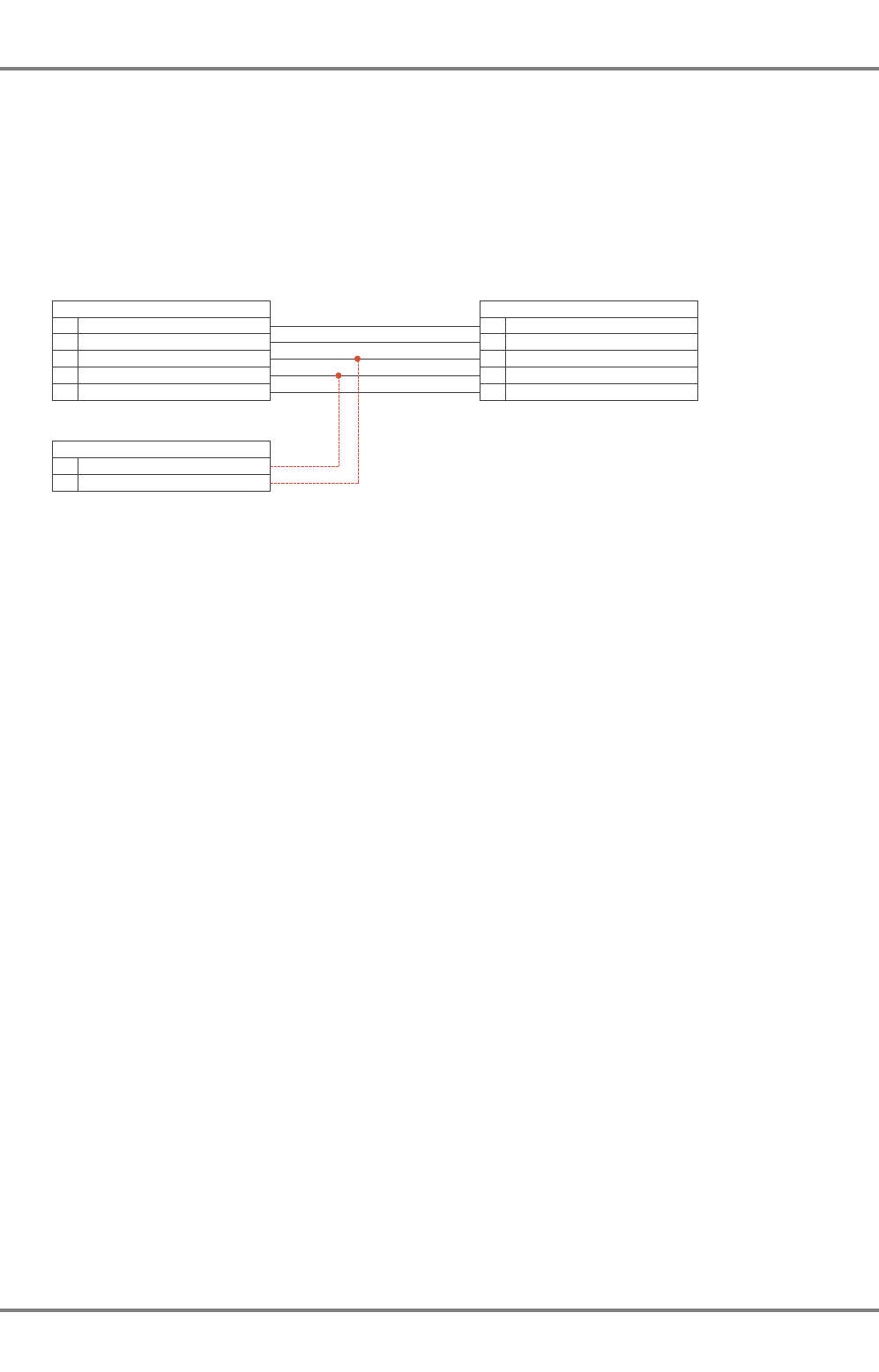
AIS 3410, Electronics Unit
ED3047G842 / 01 (2009-08)
Technical Manual
6 Repair/Maintenance
6.1 Trouble Shooting
t_ue_e07.fm / 27.08.09
50
2. Connect the AIS output TB14 and TB15 of the Analog Interface additionally to an indicator serial
interface (TB1) of the radar. If there is a free input, this one should be used. If all inputs are used,
one of them must be disconnected. Figure 6-1 shows the connection to the serial interface No. 4 as
an example.
Fig. 6-1 Cable connection for the interface monitoring Radar > AIS
3. Power on the radar. Configure the concerned indicator serial interface by means of the System Main-
tenance Manager as follows
Path:
Configure > Radar > Indicator > Indicator x > Serial Interfaces > Serial I/O x
Parameters:
-Driver, set to NMEA183 (IEC 61162-1/2)
-Baud Rate, set to 38400
-Wind, set to Connected (if the interface has been used for a ship’s sensor with NMEA183
(IEC 61162-1/2) protocol beforehand, it is not necessary to modify this parameter.)
4. The Serial I/O Monitor must be started.
Path:
Service > Indicator > Serial I/O Monitor
Select the used interface from the drop down list and mark the check box Rx. Start the monitoring
by clicking on Run. The protocol can be saved on a diskette.
z_ue_025.pdf
Analog Interface
Interconnection Board
RADARPILOT/CHARTRADAR
MULTIPILOT 1000/1100
AIS Electronics Unit
Primary Display Port
810
16
Output -AIS RxD, Input -
RxD4, Input +
Output +AIS RxD, Input +
RxD4, Input -
Input -AISTxD, Output -
Input +
GND
AISTxD, Output +
GND
Connector 2TB
TB1 Indicator Serial Interface 4
614
5
1
15
16
711
17

AIS 3410, Electronics Unit
ED3047G842 / 01 (2009-08)
Technical Manual
6 Repair/Maintenance
6.1 Trouble Shooting
t_ue_e07.fm / 27.08.09
51
Fig. 6-2 Protocol Radar TxD
If the AIS voyage data is modified or safety related messages are sent, the protocol must show tele-
grams corresponding to the telegrams in Figure 6-2. If there is no communication on the interface,
the Analog Interface is defective or has a wrong software version (The software version must be F
or newer. To check the software version, use the Telemonitoring Data menu of the System Main-
tenance manager. The line for the Analog Interface must look as follows: SIR10T GE3044P207 F)
or the configuration of the radar is faulty. See the Technical Manual of the radar for further informa-
tion.
NOTE:
If a ship’s sensor is connected to the interface which has been used for the test, it must be made
sure, that all modifications of the parameterization of this interface that were necessary for the test
are cancelled.
Test of the AIS 3410 Output
1. Power Down the system
2. Connect the AIS Primary Display Port TB7 and TB8 additionally to an indicator serial interface (TB1)
of the radar. If there is a free input, this one should be used. If all inputs are used, one of them must
be disconnected. Figure 6-1 shows the connection to the serial interface No. 4 as an example.
$PSAEAISALV*07
$RAVSD,69,12.0,0,BREMEN,142000.00,06,11,7,0*67
$PSAEAISALV*07
$PSAEAISALV*07
$PSAEAISALV*07
$PSAEAISALV*07
!RABBM,2,1,0,0,14,7B?E>49>7P<1DrkjriqfknhP>P<?>rihpripfinhPGPD9=5r>?FPimPinr,0*6E
!RABBM,2,2,0,0,14,ipPED3P31<<C97>rC1=P>1=5r=He=1B9>5PD5CDP==C9rjiijhoonh,0*79
$PSAEAISALV*07
$PSAEAISALV*07
$PSAEAISALV*07
$PSAEAISALV*07
Alive message, sent every 15 seconds
Voyage Data has been
modified at the Indicator.
Safety related messages
have been sent.
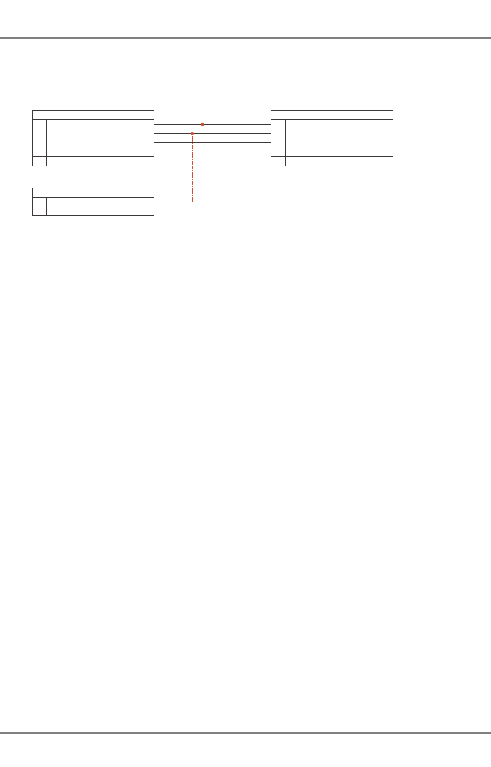
AIS 3410, Electronics Unit
ED3047G842 / 01 (2009-08)
Technical Manual
6 Repair/Maintenance
6.1 Trouble Shooting
t_ue_e07.fm / 27.08.09
52
Fig. 6-3 Cable connection for the interface monitoring AIS > Radar
3. Power on the radar. Configure the concerned indicator serial interface by means of the System Main-
tenance Manager as follows
Path:
Configure > Radar > Indicator > Indicator x > Serial Interfaces > Serial I/O x
Parameters:
-Driver, set to NMEA183 (IEC 61162-1/2)
-Baud Rate, set to 38400
-Wind, set to Connected (if the interface has been used for a ship’s sensor with NMEA183
(IEC 61162-1/2) protocol beforehand, it is not necessary to modify this parameter.)
4. The Serial I/O Monitor must be started.
Path:
Service > Indicator > Serial I/O Monitor
Select the used interface from the drop down list and mark the check box Rx. Start the monitoring
by clicking on Run. The protocol can be saved on a diskette.
z_ue_026.eps
Analog Interface
Interconnection Board
RADARPILOT/CHARTRADAR 1000/1100 AIS Electronics Unit
Primary Display Port
810
16
Output -AIS RxD, Input -
RxD4, Input +
Output +AIS RxD, Input +
RxD4, Input -
Input -AISTxD, Output -
Input +
GND
AISTxD, Output +
GND
Connector 2TB
TB1 Indicator Serial Interface 4
614
5
1
15
16
711
17

AIS 3410, Electronics Unit
ED3047G842 / 01 (2009-08)
Technical Manual
6 Repair/Maintenance
6.1 Trouble Shooting
t_ue_e07.fm / 27.08.09
53
Fig. 6-4 Protocol AIS TxD
Figure 6-4 shows the protocol which has been transmitted by a AIS. The alarm messages can be
forced by disconnecting the sensors and/or the VHF antenna.
If there is no communication on the interface, the AIS is not working. If the power supply and the
cable connection are correct, the AIS Electronics Unit seems to be defective.
NOTE:
If a ship’s sensor is connected to the interface which has been used for the test, it must be made
sure, that all modifications of the parameterization of this interface that were necessary for the test
are cancelled.
!AIVDO,2,2,0,B,00000000000,2*25
!AIVDO,1,1,,,139K6D7037H@L7FBOLDCr39R0000,0*3D
!AIVDO,1,1,,A,139K6D7037H@L7FBOLDCr39R08AM,0*78
!AIVDO,1,1,,,139K6D7037H@L9:BOLBCr39T0000,0*4F
$AITXT,1,1,31,AIS: Heading valid*0D
$AITXT,1,1,34,AIS: Other ROT source in use*62
!AIVDO,1,1,,,139K6D7037H@L;DBOL=kr39V0000,0*66
!AIVDM,1,1,,B,1000O@B038H@L:vBOL>Cr39V08Bg,0*65
!AIVDO,1,1,,,139K6D7037H@L=FBOL;kr39`0000,0*52
!AIVDO,1,1,,,139K6D7037H@L?LBOL9kr39b0000,0*5A
!AIVDO,1,1,,B,139K6D7037H@L?LBOL9kr39b0D01,0*6D
!AIVDO,1,1,,,139K6D7037H@LALBOL7Sr39d0000,0*14
!AIVDO,1,1,,,139K6D7037H@LC<BOL5Sr39f0000,0*66
!AIVDO,1,1,,,139K6D7038H@LEFBOL3Cr39h0000,0*0D
!AIVDO,1,1,,,139K6D7038H@LGLBOKvkr39j0000,0*6D
!AIVDM,1,1,,A,1000O@B038H@LE2BOL3kr39h0HF7,0*62
!AIVDO,1,1,,,139K6D7038H@LIRBOKtkr39l0000,0*79
!AIVDO,1,1,,,139K6D7038H@LK`BOKrkr39n0000,0*4D
!AIVDO,1,1,,,1000O@OP000`VR4NGvG@0?vF0000,0*53
$AIALR,122514.85,025,A,V,AIS: external EPFS lost*21
$AIALR,122514.85,032,A,V,AIS: Heading lost/invalid*0C
$AITXT,1,1,25,AIS: internal GNSS in use*5C
$AITXT,1,1,28,AIS: internal SOG/COG in use*67
!AIVDO,1,1,,,1000O@OP000`VR4NGvG@0?vH0000,0*5D
$AIALR,122515.86,035,A,V,AIS: no valid ROT information*49
!AIVDO,1,1,,,1000O@OP000`VR4NGvG@0?vJ0000,0*5F
!AIVDO,1,1,,,1000O@OP000`VR4NGvG@0?vV0000,0*43
$AIALR,122522.93,001,A,V,AIS: Tx malfunction*52
Status messages of the connected
sensors, sent every minute
Position report
Alive message,
every second
Another AIS has
been received
Alarm: External
position data
not available
Alarm: Heading
data not avail-
able
Alarm: VHF
transmission
does not work

AIS 3410, Electronics Unit
ED3047G842 / 01 (2009-08)
Technical Manual
6 Repair/Maintenance
6.2 Test of the Antenna Performance
t_ue_e07.fm / 27.08.09
54
6.1.3.2
Indication: System Fault Message 3616 Displayed on Indicator
If the system fault message 3616 is displayed, it is likely that the problems are caused by the Analog
Interface if the AIS is connected via the Primary Display Port.
Procedure:
1. Check the configuration of the Analog Interface. See the Technical Manual of the RADARPILOT
1000/1100 for further information.
2. Check the correct setting of the S1 and the jumpers of the Interface Assembly SH3014G203. S1
must be set to position 2. No jumpers should be connected to the pins 1...4. See the Technical
Manual of the RADARPILOT 1000/1100 for further information.
3. Check the software version of the Analog Interface. The software version must be F or newer. To
check the software version, use the Telemonitoring Data menu of the System Maintenance
manager. The line for the Analog Interface must look as follows:
SIR10T GE3044P207 F
6.2 Test of the Antenna Performance
With the AIS 3410 Electronics Unit is possible to measure the voltage standing wave ratio (VSWR) of the
VHF antenna.
The measured values have the following meaning:
- 1.0...1.5: The antenna installation and cabling is good.
- 1.6...2.0: The antenna installation and cabling (cabling laying, antenna position and connectors)
should be checked and improved.
>2.0: Poor antenna installation
6.3 Software Update
A software update can be performed by means of a laptop (or any other PC with Windows 95, 98, XP,
Vista as its operating system), a cable and the service software, which is available in the SAM-CMIS
system (see Section 6.3.1).
If the AIS is connected to a CHARTPILOT or MULTIPILOT, it is also possible to update the software by
means of the CHARTPILOT/MULTIPILOT and the CHARTPILOT Application Software CD. See the Tech-
nical Manuals of the CHARTPILOT or MULTIPILOT for further information.
6.3.1 Software download from SAM-CMIS
The current and previous versions of the software and the documentation for all components of the AIS
system can be downloaded from the internet.
Preconditions:
- Internet Explorer 5.5 (with Virtual Machine) or newer
- "Cookies" must be accepted
Only authorized person have access to SAM-CMIS. To gain access enter the address:
https://www.sam-cmis.de/livelink/llisapi.dll?func=ll&objId=4826402&objAction=browse
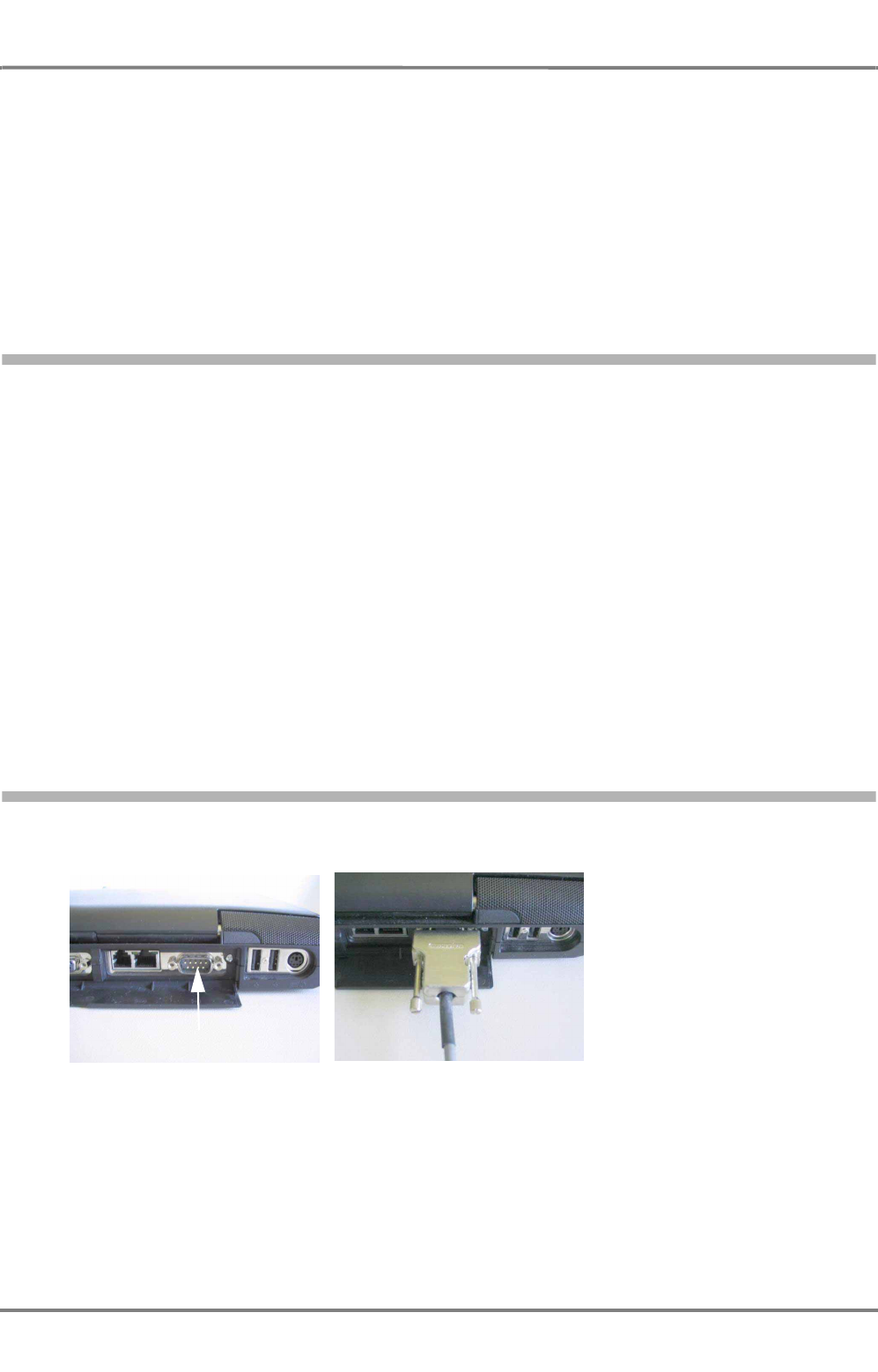
AIS 3410, Electronics Unit
ED3047G842 / 01 (2009-08)
Technical Manual
6 Repair/Maintenance
6.3 Software Update
t_ue_e07.fm / 27.08.09
55
You are now requested to fill in your username and password. Afterwards you are redirected to the
folder with the newest zip file containing the software for all components of the AIS system. The
unpacked zip file can be saved on a CD ROM.
It is not permissible to modify any settings in the SAM-CMIS system. To leave the system click on Tools
-> Log-out.
Overview/Hints
A table of the software versions, their compatibility and the corresponding versions of the manuals is
shown in a README-file which is part of the downloaded zip file.
6.3.2 Determination of the Current Software Versions
AIS 3410 with RADAR/CHARTRADAR/MULTIOPILOT 1000/1100
Open the System Maintenance Manager by clicking Menu -> Utilities -> Maintenance. Select the
register card Telemonitoring Data and click on the Version button at the lower left.
The software versions of the radar and of connected systems are displayed. Use the scrollbar to
search for the AIS software versions.
AIS 3410 with RADAR 9x00 and MULTIPILOT 910x (Radar Mode):
Press the Menu button. Select Utilities -> Self Check -> Version.
Use the CANCEL/MORE button to toggle through the pages until the AIS page is reached.
AIS 3410 with MULTIPILOT 910x (ECDIS Mode):
Open the tree structure by clicking the Tree button.
Click on System Maintenance -> Version... to display the software versions of the MULTIPILOT
and all connected systems.
6.3.3 Serial Cable Connection
Connection at the PC/Laptop
The serial cable must be
connected to COM 1 of the PC/
Laptop.
Fig. 6-5 Connection to the Laptop
COM 1
z_ue_050.jpg
z_ue_051.jpg
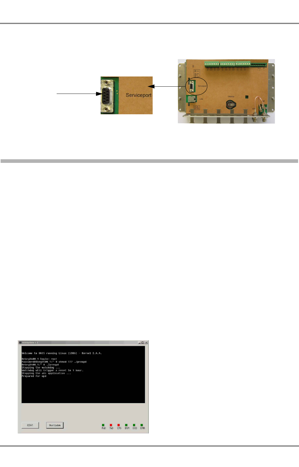
AIS 3410, Electronics Unit
ED3047G842 / 01 (2009-08)
Technical Manual
6 Repair/Maintenance
6.3 Software Update
t_ue_e07.fm / 27.08.09
56
Connection at the Electronics Unit
The cable must be connected to the serial service interface of the computer and to the connector on the
top of the Electronics Unit’s port
Fig. 6-6 Service Interface
6.3.4 Software Update by means of a Laptop
1. Disconnect the Electronics Unit from the power supply for about 5 s.
2. Connect the power supply and wait about 2 minutes until the Electronics Unit has been restarted.
3. Connect the update cable before the update software is started.
4. Download the update from the SAM-CMIS system (see Section 6.3.1), unzip the file and save the
unzipped directory structure to the hard disk or on a CD ROM.
5. To start the update software open the directory of the software version which shall be installed
(usually the newest version; for details see the readme file)
DOS command line:
CD X:\AIS\ElectronicsUnit3410\BuildNNN_YYYYMMDD\root
(DRIVE X name of the drive, NNN = release of the software, YYYY=year, MM=month, DD=day)
Type aisupdate.exe to start the software.
Type aisupdate.exe on the command line to start the program.
Windows Explorer:
Open the Windows Explorer and select the drive with the update directory.
Select the following path by clicking twice on the directory names: AIS -> ElectronicsUnit3410
-> BuildNNN_YYYY_MM_DD -> root
Start the program aisupdate.exe by clicking twice on the corresponding icon.
6. Click the Start Update button.
If a failure message appears, press the COM 1 button to switch the serial port used by the program
to COM 2.
Service Interface
z_ue_052.jpg
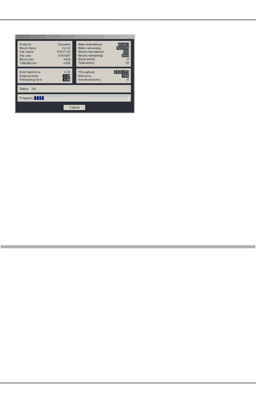
AIS 3410, Electronics Unit
ED3047G842 / 01 (2009-08)
Technical Manual
6 Repair/Maintenance
6.3 Software Update
t_ue_e07.fm / 27.08.09
57
7. A status windows appears during the update.
8. It must be waited until the message "Flash programming finished, system is rebooting" appears.
9. The Electronics Unit reboots automatically. The OK button closes the window of the update routine.
10. Verify the proper function of the system, make sure that AIS targets and sensor data will be
displayed on the connected display system.
11. Verify that the Update was successful and the new software version is installed.
WARNING!
Do not interrupt the update! If update procedure is interrupted, the Elec-
tronics Unit may come into an undefined status, in which no further
update or operation is possible. See Section 6.3 on page 54 in this case.
During the update the new software is stored in the RAM module of the AIS. After the successful transfer
the old version will be deleted by erasing the Flash ROM. Then the update file will be stored on the Flash
ROM.
If the power supply was interrupted during the update process, it may occur in seldom cases, that the
electronics unit is not restarting again. In this case it may necessary to exchange the Disk On Chip
memory module.
6.3.5 Software Update by means of a CHARTPILOT or MULTIPILOT 91x0
If a CHARTPILOT or MULTIPILOT 91x0 is connected (the AIS Electronics Unit must be connected to the
LAN), it is possible to update the AIS by means of one of these systems. The update of the AIS Elec-
tronics Unit is possible from CHARTPILOT/MULTIPILOT software version 5.1 onwards.
WARNING!
Do not change any CHARTPILOT settings while doing the software
update via CHARTPILOT or MULTIPILOT. This may cause problems of
the ECDIS application and can degrade the performance of your naviga-
tion system.
1. Put the Update CD ROM in the CD ROM drive of the CHARTPILOT.
2. Open the System Maintenance menu (Tree => System Maintenance).
3. Open the Configuration menu and input the service password.
4. Open the AIS menu and start the software update program.
z_ue_053.jpg
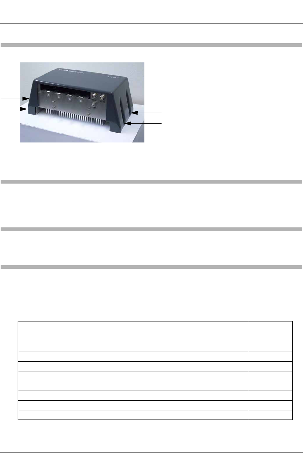
AIS 3410, Electronics Unit
ED3047G842 / 01 (2009-08)
Technical Manual
6 Repair/Maintenance
6.4 Opening the Housing
t_ue_e07.fm / 27.08.09
58
6.4 Opening the Housing
Opening of the Electronics Unit housing of AIS 3410
Undo the four screws in the cover. To close the housing, proceed in the reverse order.
6.4.1 Fuses
Electronics Unit
The Electronics Unit contains no fuses.
6.4.2 Antennas
If one of the antennas is defective, it must be exchanged. See the Spare Part List for the order number.
6.5 Spare Parts
Some of the components may be modified at short intervals, so that it is likely that it will not be possible
to deliver spare parts which are absolutely identical to the original part. In such cases, a Technote for the
exchange is delivered with the spare part and new versions of components are added to this manual as
soon as possible.
Description Order Number
Electronics Unit 271259341
Battery,Lithium CR2032 271126851
Media Converter (BNC -> RJ-45) 271259883
RJ-45 Ethernet LAN patch cable (Kat.5e, SFTP, RJ45, 1m, grau) 390006203
GPS Antenna 271257889
VHF Antenna 271259204
Housing fan, external fan (only for UAIS DEBEG 3400 housing) 300006159
Filter pad for housing fan, set with 5 pcs (only for UAIS DEBEG 3400 housing) 300006161
Air inlet (filter holder for housing fan) (only for UAIS DEBEG 3400 housing) 300006160

AIS 3410, Electronics Unit
ED3047G842 / 01 (2009-08)
Technical Manual
7 Technical Data
7.1 Conformity to Standards, Environmental Conditions
t_ue_e08.fm / 27.08.09
59
7 Technical Data
7.1 Conformity to Standards, Environmental Conditions
The AIS 3410 Electronics Unit is complient with DIN EN 60945 (Maritime navigation and radiocommuni-
cation equipment and systems - General requirements - Methods of testing and required test results).
The Electronics Unit belongs to the category "protected from the weather".
The antennas belong to the category "exposed to the weather".
The AIS 3410 complies with EN 61993-2:2002.
The interfaces of the AIS 3410 comply with IEC 61162-1:2007 (3rd Edition) and IEC 61162-2:1998.
7.2 Performance
7.2.1 Performance Data of the Electronics Unit
General
Housing: IP22
Operating temperature: -15...+55°C (DIN EN 60945)
Humidity: Max. 95% at 40°C (DIN EN 60945)
DC voltage (supply): 24 VDC ±20%
DC current (consumption): Typ. 0.76 A at 24 V, max. 2.5 A (momentarily during transmission)
GPS Receiver
Receiver architecture: Single board receiver
Channels: 16, parallel
Time to first fix: Hot start 3.5 s
Warm start 33 s
Cold start 36 s
Navigation modes: 3-D and 2-D, depending on the number of tracked satellites.
Accuracy: Position 2.5m CEP
VHF Transceiver
The Transceiver corresponds to EN 61993-2:2002, chapter 15
Transmitting power: 2 W / 12.5 W / ≤1 W
Input sensitivity: -107 dBm (AIS and DSC)
Low Power mode for Tanker
Tanker Normal
high 12.5 W 12.5 W
low ≤1 W 2 W
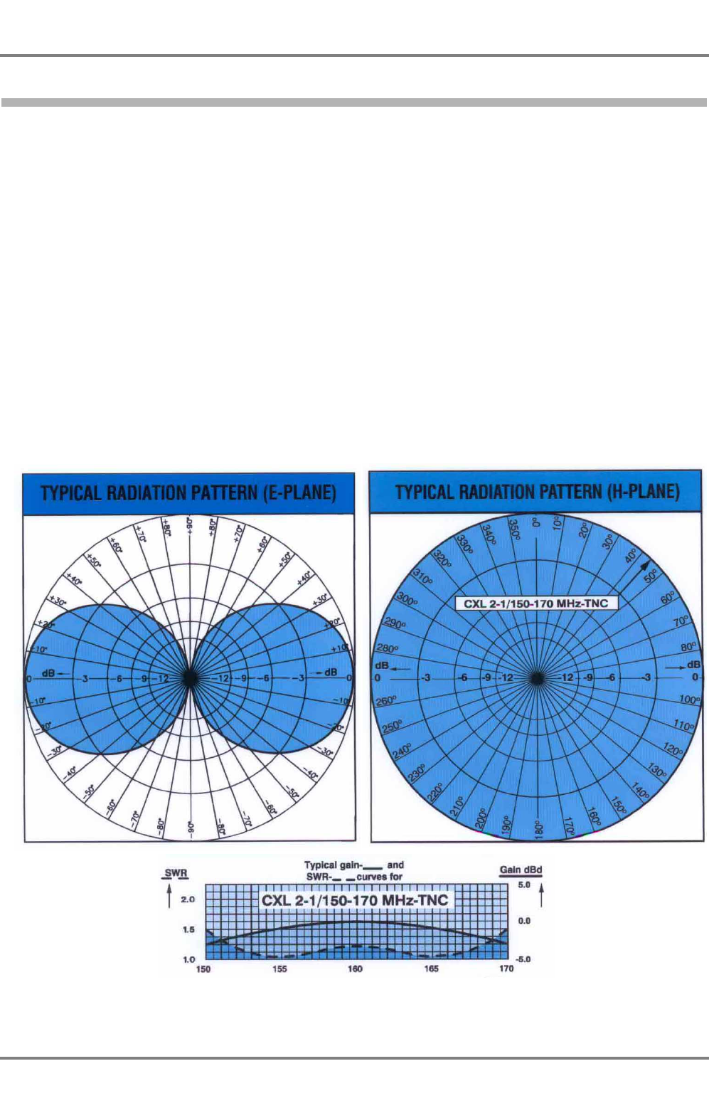
AIS 3410, Electronics Unit
ED3047G842 / 01 (2009-08)
Technical Manual
7 Technical Data
7.2 Performance
t_ue_e08.fm / 27.08.09
60
7.2.2 Performance Data of the VHF Antenna CLX 2-1/150-170 MHz
Antenna type: ½λ coaxial, broad band
Frequency: 150...170 MHz
Impedance: Nom. 50 Ω
Polarization: Vertical
Gain: 2 dBi, 0 dBd
Bandwith: 20 MHz
SWR: < 1.5
Max. power: 150 W
Connector: TNC female
Wind load: 21.8 (at 150 km/h)
Material: Whip = Glassfibre
Colour: Marine white
Total length: Approx. 1.2 m
Weight: Approx. 340 g
Mounting: 1" threaded mast tube
For the outline drawings see Section 10.
z_ue_407.pdf
z_ue_408.pdf
z_ue_409.pdf

AIS 3410, Electronics Unit
ED3047G842 / 01 (2009-08)
Technical Manual
7 Technical Data
7.3 Dimensions and Weights
t_ue_e08.fm / 27.08.09
61
7.2.3 Performance Data of the GPS Antenna
General:
Color: White
Weight: 163 g
Nominal RF input: TNC female
Operating temperature: -40...+85°C
Humidity: 95% relative humidity
Antenna Element:
Frequency: 1575.42 ±10.0 MHz
Impedance: 50 Ω
Nominal VSWR: 1.5:1 max.
Polarization: Right hand circular
Gain: +4.5 dBiC nom.
Low Noise Amplifier:
Frequency: 1575.42 ±10 MHz (GPS L1)
Impedance: 50 Ω
Nominal output VSWR: 2.0:1
Max. gain: 26.5 ±3 dB
DC voltage (supply): 5...26 VDC through connector
DC current (consumption): 25 mA typ., 40 mA max.
Filtering: Dual ceramic filter
7.3 Dimensions and Weights
For dimensions and weights, see the technical drawings. The drawings are shown in Section 10.
7.4 Compass Safe Distances
Standard
compass
Steering
compass
Standard
compass reduced
Steering compass
reduced
Electronics Unit
3410 0.4 m 0.3 m 0.3 m 0.3 m
VHF Antenna CXL 2-1 0.3 m 0.3 m 0.3 m 0.3 m
GPS Antenna 1330FB 0.3 m 0.3 m 0.3 m 0.3 m

AIS 3410, Electronics Unit
ED3047G842 / 01 (2009-08)
Technical Manual
7 Technical Data
7.4 Compass Safe Distances
t_ue_e08.fm / 27.08.09
62

AIS 3410, Electronics Unit
ED3047G842 / 01 (2009-08)
Technical Manual
8 Fault Code List
t_ue_e09.fm / 27.08.09
63
8 Fault Code List
The following fault codes (integrity alarm conditions) can be displayed at the connected display unit (for
example a RADARPILOT 1000/1100). See also Section 6 from page 47 on for further information.
Fault
Messages at Error Message generated by,
Possible Cause/Source,
Reaction of the System,
Remedy
1000/1100 Series,
CHARTPILOT,
MULTIPLOT 910x
(Chart Mode)
Radar 9xxx, MULTIP-
ILOT 910x (Radar
Mode)
001 AIS: Tx malfunction AIS TX MALFUNCTION
Generated by: AIS Electronics Unit
Cause/Source: VHF Antenna, cabling
Reaction: The Electronics Unit stops the transmission.
Remedy: Check of the antenna and the antenna cabling
(short circuit or missing contact at the connectors)
002
AIS: Antenna
VSWR exceeds limit
(VSWR = Voltage
Standing Wave
Ratio)
AIS VSWR LIMIT
Generated by: AIS Electronics Unit
Cause/Source: VHF antenna, installation
Reaction: The Electronics Unit continues operation.
Remedy: Check of the antenna and the antenna cabling
(75 Ω cable instead of 50 Ω cable)
003 AIS: Rx channel 1
malfunction AIS RX CH1 FAULT Generated by: AIS Electronics Unit
Cause/Source: Internal error
Reaction: The Electronics Unit stops the transmission on the
affected channel.
Remedy: The Electronics Unit must be exchanged.
004 AIS: Rx channel 2
malfunction AIS RX CH2 FAULT
005 AIS: Rx channel 70
malfunction AIS RX CH70 FAULT
006 AIS: General failure AIS GENERAL FAULT
Generated by: AIS Electronics Unit
Cause/Source: Internal error
Reaction: The Electronics Unit stops the transmission.
Remedy: The Electronics Unit must be exchanged.
008
AIS: MKD connec-
tion lost (MKD =
Minimum Keyboard
Display)
AIS CONNECTION
Generated by: AIS Electronics Unit
Cause/Source: No Operating/Display Unit connected
Reaction: The Electronics Unit continues operation.
Remedy: The Display Unit (for example a RADARPILOT
1x00) does not communicate with the Electronics Unit. Check
the cabling/connection of the Primary Display Port. Check if
the Display Unit is working.
025
AIS: External EPFS
lost
(EPFS = Electronic
Position Fixing
System such as
GPS)
AIS EXTERNAL EPFS
Generated by: AIS Electronics Unit
Cause/Source: No valid position data at interface S1, S2, S3
Reaction: The Electronics Unit continues operation with the
position data of the internal position sensor. If there is no
valid position data available from the internal position sensor,
additionally error 026 is displayed.
Remedy: The telegrams GLL, GNS, GGA, RMC can not be
received. Check the sensor and the cabling; Check if the
system that delivers the data is working (RADARPILOT
1x00); Check the baud rate settings of the sensor inputs.
026 AIS: No sensor
position in use AIS NO POSITION
Generated by: AIS Electronics Unit
Cause/Source: No valid position from internal position sensor
Reaction: The Electronics Unit continues operation.
Remedy: Check the cabling and the antenna of the internal
GPS sensor.

AIS 3410, Electronics Unit
ED3047G842 / 01 (2009-08)
Technical Manual
8 Fault Code List
t_ue_e09.fm / 27.08.09
64
029 AIS: No valid SOG
information AIS NO SOG
Generated by: AIS Electronics Unit
Cause/Source: No data from external sensor and from
internal position sensor
Reaction: The Electronics Unit continues operation.
Remedy: The telegrams VBW, VTG, RMC can not be
received. Check the sensor and the cabling; Check if the
system that transmits the data is working (RADARPILOT
1x00); Check the baud rate settings of the sensor inputs.
030 AIS: No valid COG
information AIS NO COG
Generated by: AIS Electronics Unit
Cause/Source: No data from external sensor and from
internal position sensor
Reaction: The Electronics Unit continues operation.
Remedy: The telegrams VTG, RMC can not be received.
Check the sensor and the cabling; Check if the system that
transmits the data is working (RADARPILOT 1x00); Check
the baud rate settings of the sensor inputs.
032 AIS: Heading lost/
invalid AIS NO HEADING
Generated by: AIS Electronics Unit
Cause/Source: No data from external sensor
Reaction: The Electronics Unit continues operation.
Remedy: The telegrams HDT can not be received. Check the
sensor and the cabling; Check if the system that transmits
the data is working (RADARPILOT 1x00); Check the baud
rate settings of the sensor inputs.
035 AIS: No valid ROT
information AIS NO ROT
Generated by: AIS Electronics Unit
Cause/Source: No data from external sensor
Reaction: The Electronics Unit continues operation.
Remedy: The telegrams ROT can not be received. Check the
sensor and the cabling; Check if the system that transmits
the data is working (RADARPILOT 1x00); Check the baud
rate settings of the sensor inputs.
051
AIS: Channel
management infor-
mation not accepted
AIS SET CHANNELS
Generated by: AIS Electronics Unit
Cause/Source: E.g. overlapping with an existing area
Reaction: The Electronics Unit continues operation.
Remedy: Check the channel management information.
052 AIS: GPS receiver
fault AIS GPS RECEIVER
Generated by: AIS Electronics Unit
Cause/Source: Internal GPS receiver malfunction
Reaction: The Electronics Unit continues operation without
internal GPS data and without direct GPS time synchroniza-
tion.
Remedy: The Electronics Unit must be exchanged.
053
AIS: GPS antenna
not connected or
defective
Generated by: AIS Electronics Unit.
Cause/Source: No connection with the GPS antenna
Reaction: The AIS Electronics Unit continues operation
without direct GPS syncronisation.
Remedy: Renew proper connection with the GPS antenna
and/or substitute the defective GPS antenna.
Fault
Messages at Error Message generated by,
Possible Cause/Source,
Reaction of the System,
Remedy
1000/1100 Series,
CHARTPILOT,
MULTIPLOT 910x
(Chart Mode)
Radar 9xxx, MULTIP-
ILOT 910x (Radar
Mode)

AIS 3410, Electronics Unit
ED3047G842 / 01 (2009-08)
Technical Manual
8 Fault Code List
t_ue_e09.fm / 27.08.09
65
054 AIS: GPS antenna
short circuit
Generated by: AIS Electronics Unit.
CauseSource: Short circuit in the cable/connectors or within
the GPS antenna.
Reaction: The AIS Electronics Unit continues operation
without direct GPS syncronisation.
Remedy: Renew proper connection with the GPS antenna
and/or substitute the defective GPS antenna. Restart the AIS
Electronics Unit.
0204 AIS: offline AIS OFFLINE
Generated by: AIS Electronics Unit
Cause/Source: No connection between Display and Elec-
tronics Unit, no valid IEC 61162 data or reset caused by the
watchdog
Reaction: The Electronics Unit continues operation.
Remedy: The cabling must be checked. It might be possible
to eliminate the fault by switching the voltage supply to the
AIS electronics unit off and then on again at the ship's mains.
Reaction: The message was displayed for a short time during
a reset of the system that was caused by the internal
watchdog. The Electronics Unit continues operation.
-AIS Transmitter Off AIS TRANSM. OFF
Generated by: AIS Electronics Unit
Cause/Source: The transmitter has been switched off
completely by the operator, the MMSI number has not been
configured in the Configuration menu or an error appeared
which caused a stop of transmission (time out of 7 minutes).
Reaction: The Electronics Unit continues operation.
Remedy: The transmitter must be switched on or the MMSI
number must be configured. If it has not been configured
beforehand, it is set to 0 and no data is transmitted.
Remedy: Check other error messages to find the reason for
the alarm. If there are no further messages, restart the Elec-
tronics Unit by disconnecting the mains supply.
Fault
Messages at Error Message generated by,
Possible Cause/Source,
Reaction of the System,
Remedy
1000/1100 Series,
CHARTPILOT,
MULTIPLOT 910x
(Chart Mode)
Radar 9xxx, MULTIP-
ILOT 910x (Radar
Mode)

AIS 3410, Electronics Unit
ED3047G842 / 01 (2009-08)
Technical Manual
8 Fault Code List
t_ue_e09.fm / 27.08.09
66
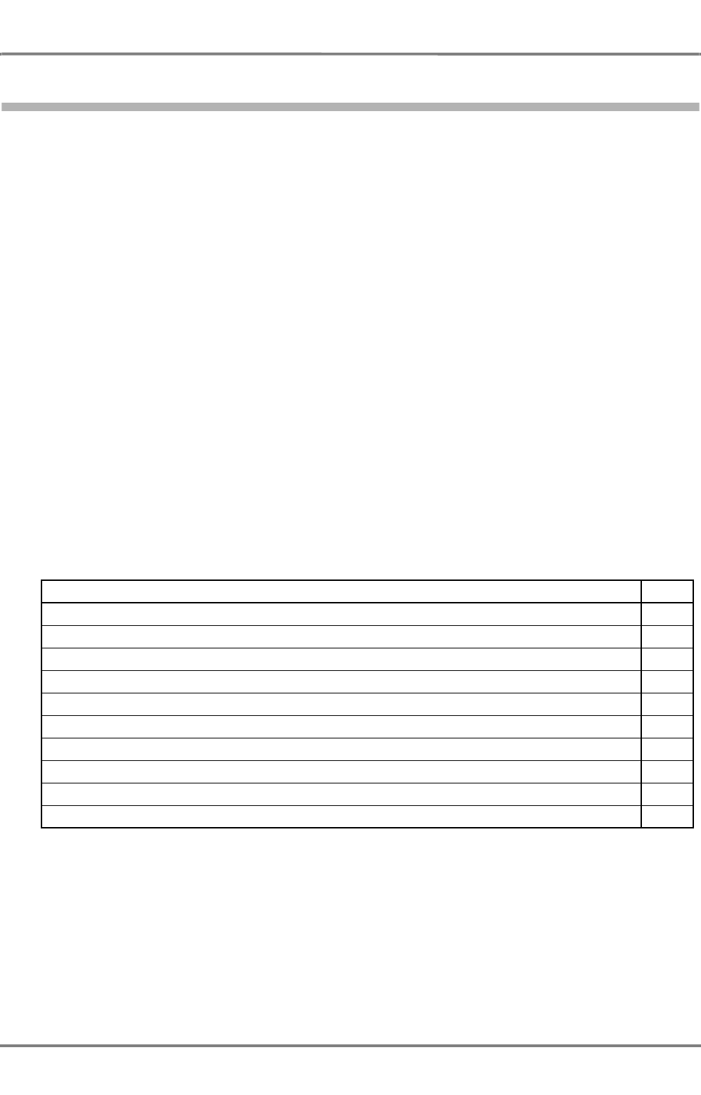
AIS 3410, Electronics Unit
ED3047G842 / 01 (2009-08)
Technical Manual
9 Cabling Documents
t_ue_e11.fm / 27.08.09
67
9 Cabling Documents
Grounding
All components of the system have contacts such as bolts or terminals for grounding. Grounding is impor-
tant for EMC purposes as well as for protecting people’s lives. Both purposes are covered by the
standard grounding of the system’s housings to the ship’s metallic structure (bolted or welded). Regard-
less of the type of ship’s grounding (e.g. star pattern or ground plane pattern), no potential difference
should be measurable between two different ground connectors. Potential differences cause compensa-
tion currents on the cable shields. If the ship has no metallic structure, all conductively connected metallic
parts form an artificial ground.
All ground connections should be as short as possible. If possible, different units should be connected to
individual ground connectors. Whenever possible, metallic housings should be screwed or welded directly
to the ship’s metallic structure. If a safe grounding contact is not ensured, additional conductors are
necessary. Furthermore, all ground connections should have a low RF-impedance, and should be
resistant against vibration and corrosion. Grounding conductors on an open-air deck must be made of
corrosion-protected steel, and inside the ship they must be made of copper.
The grounding should be done in such a way that the connection can be inspected in a convenient
manner.
EMC Purposes
The shields of all cables must be connected at both ends if no other instructions are given.
Protective Ground
All removable metallic parts of the housings are grounded by means of separate, flexible cables to the
main structure of the housing. It is important to connect this ground-cable after parts have been
dismounted or exchanged.
Title Page
Cable Diagram, connection to RADARPILOT 1x00, NACOS xx-4/5 via Primary Display Port
68
Cable Diagram, connection to CHARTPILOT, NACOS xx-4/5, RADAR / MULTIPILOT 1x00 via LAN
69
Cable Diagram, connection to CHARTPILOT stand-alone
70
Cable Diagram, connection to Radar 9xxx via Radar 9xxx AIS Interface (NACOS xx-3)
71
Detailed Cable Diagram, connection to RADARPILOT 1x00, NACOS xx-4/5 via Primary Display Port
72
Detailed Cable Diagram, Wheelhouse Console
73
Detailed Cable Diagram, connection to NACOS xx-4/5, RADAR / MULTIPILOT 1x00 via LAN
74
Detailed Cable Diagram, connection to CHARTPILOT stand-alone systems
75
Detailed Cable Diagram, connection to RADAR 9xxx AIS Interface
76
Detailed Cable Diagram, connection to RADAR 9xxx AIS Interface PCB GE 3044 G 220
77
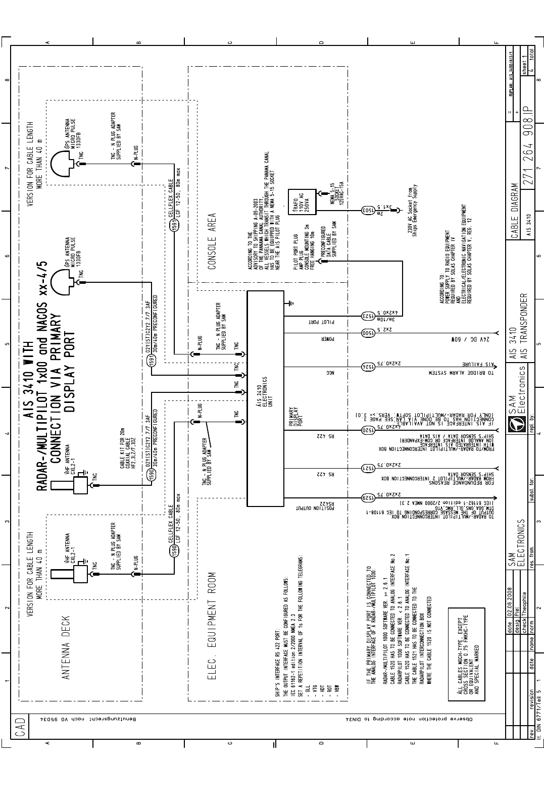
AIS 3410, Electronics Unit
ED3047G842 / 01 (2009-08)
Technical Manual
9 Cabling Documents
t_ue_e11.fm / 27.08.09
68
Fig. 9-1 Cable Diagram, connection to RADARPILOT 1x00, NACOS xx-4/5 via Primary Display Port
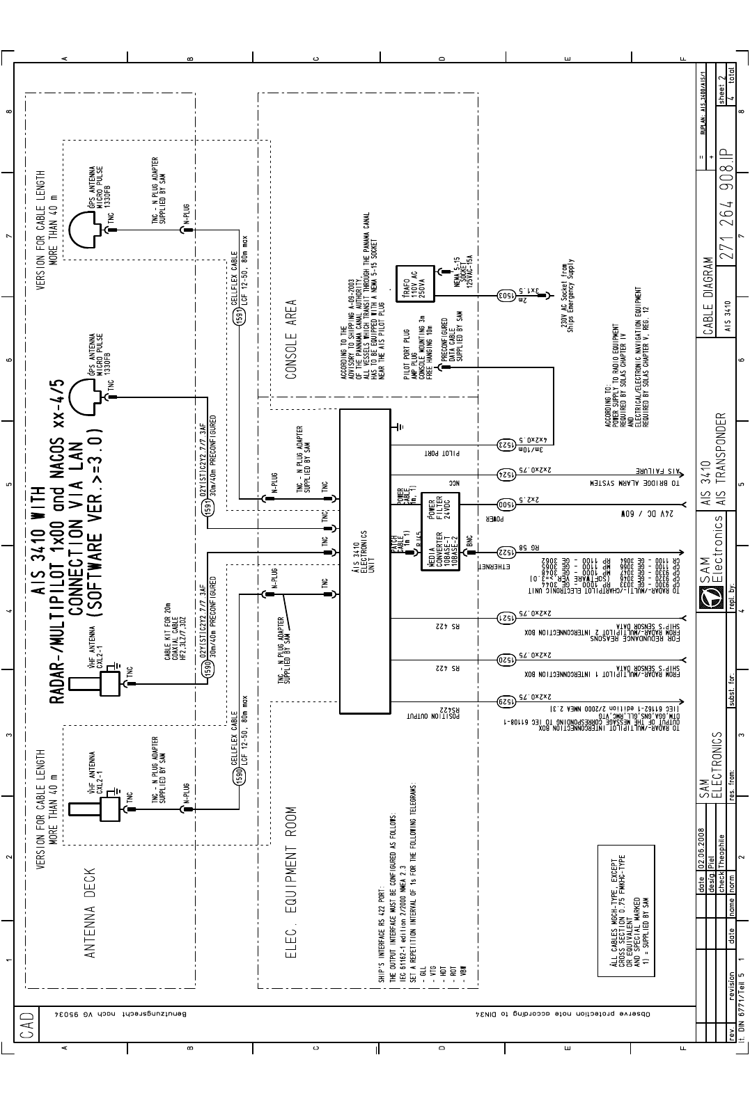
AIS 3410, Electronics Unit
ED3047G842 / 01 (2009-08)
Technical Manual
9 Cabling Documents
t_ue_e11.fm / 27.08.09
69
Fig. 9-2 Cable Diagram, connection to CHARTPILOT, NACOS xx-4/5, RADAR / MULTIPILOT 1x00 via LAN
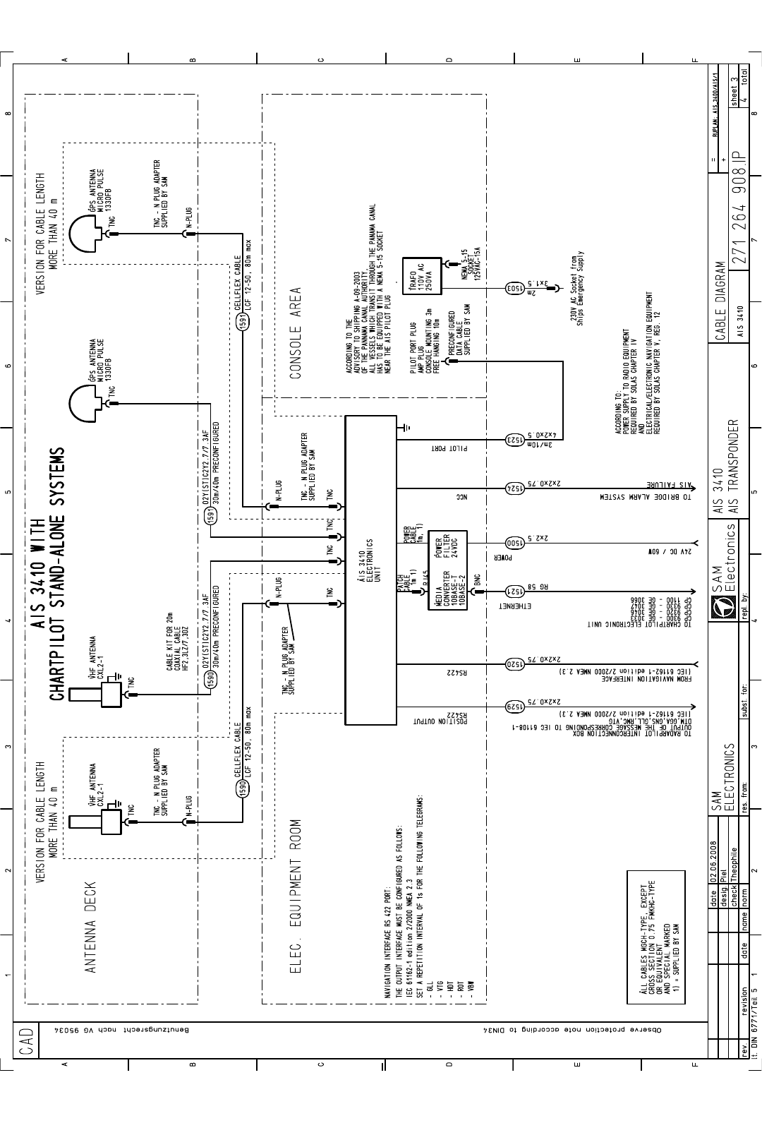
AIS 3410, Electronics Unit
ED3047G842 / 01 (2009-08)
Technical Manual
9 Cabling Documents
t_ue_e11.fm / 27.08.09
70
Fig. 9-3 Cable Diagram, connection to CHARTPILOT stand-alone
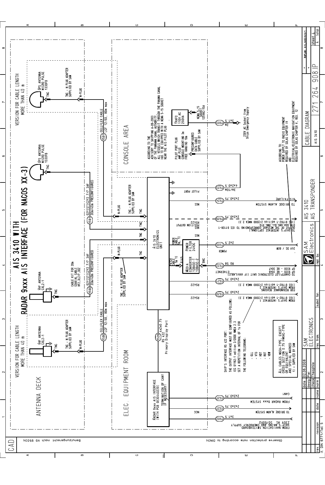
AIS 3410, Electronics Unit
ED3047G842 / 01 (2009-08)
Technical Manual
9 Cabling Documents
t_ue_e11.fm / 27.08.09
71
Fig. 9-4 Cable Diagram, connection to Radar 9xxx via Radar 9xxx AIS Interface (NACOS xx-3)
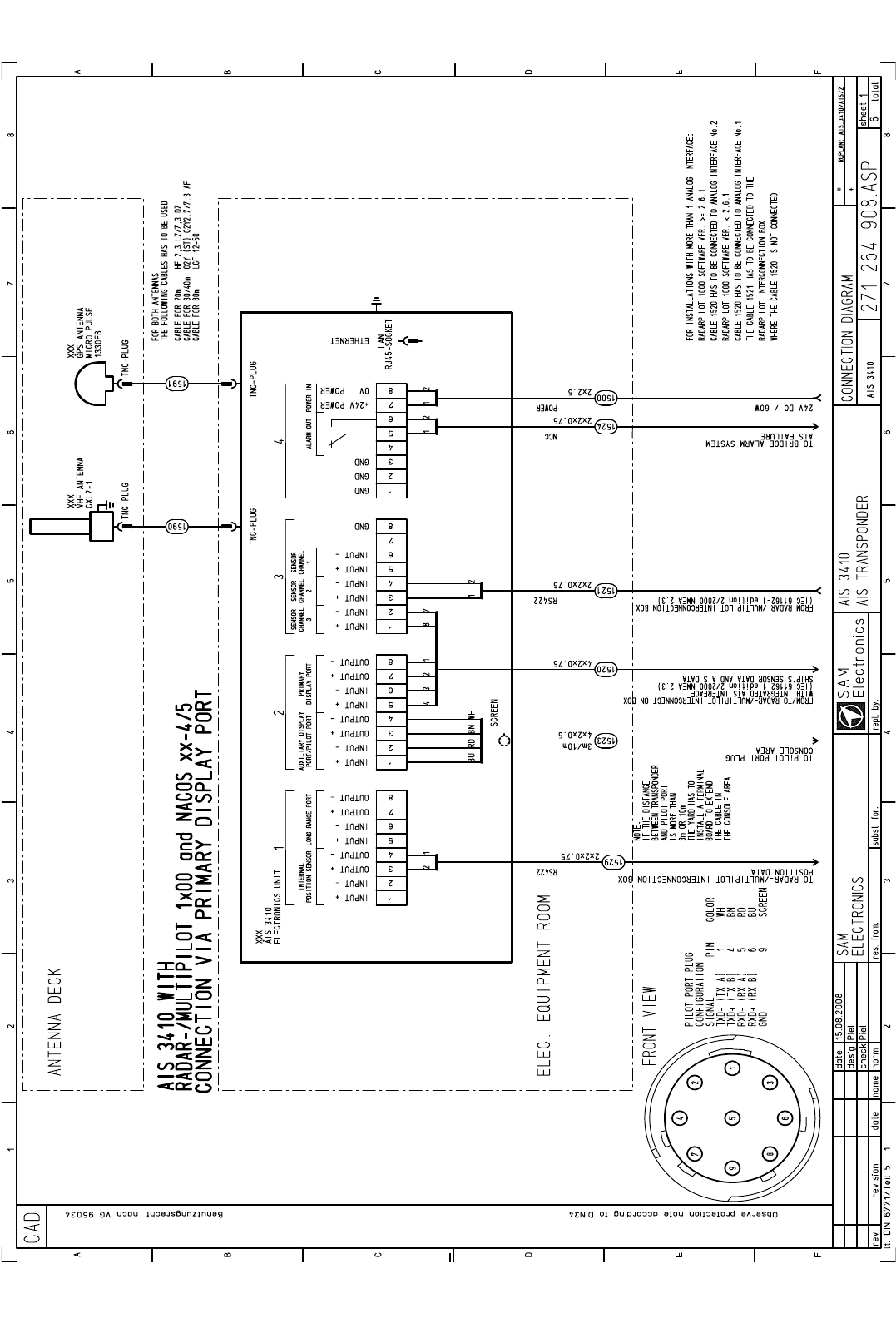
AIS 3410, Electronics Unit
ED3047G842 / 01 (2009-08)
Technical Manual
9 Cabling Documents
t_ue_e11.fm / 27.08.09
72
Fig. 9-5 Detailed Cable Diagram, connection to RADARPILOT 1x00, NACOS xx-4/5 via Primary Display Port
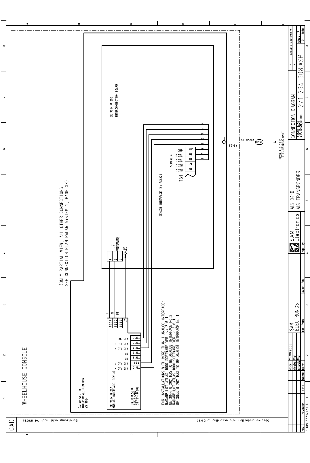
AIS 3410, Electronics Unit
ED3047G842 / 01 (2009-08)
Technical Manual
9 Cabling Documents
t_ue_e11.fm / 27.08.09
73
Fig. 9-6 Detailed Cable Diagram, Wheelhouse Console
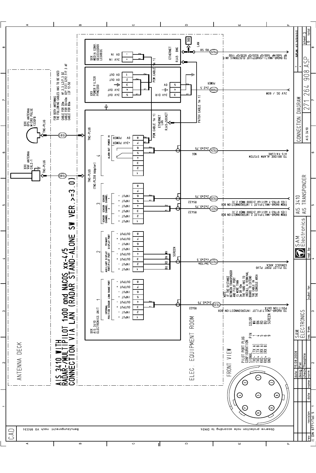
AIS 3410, Electronics Unit
ED3047G842 / 01 (2009-08)
Technical Manual
9 Cabling Documents
t_ue_e11.fm / 27.08.09
74
Fig. 9-7 Detailed Cable Diagram, connection to NACOS xx-4/5, RADAR / MULTIPILOT 1x00 via LAN
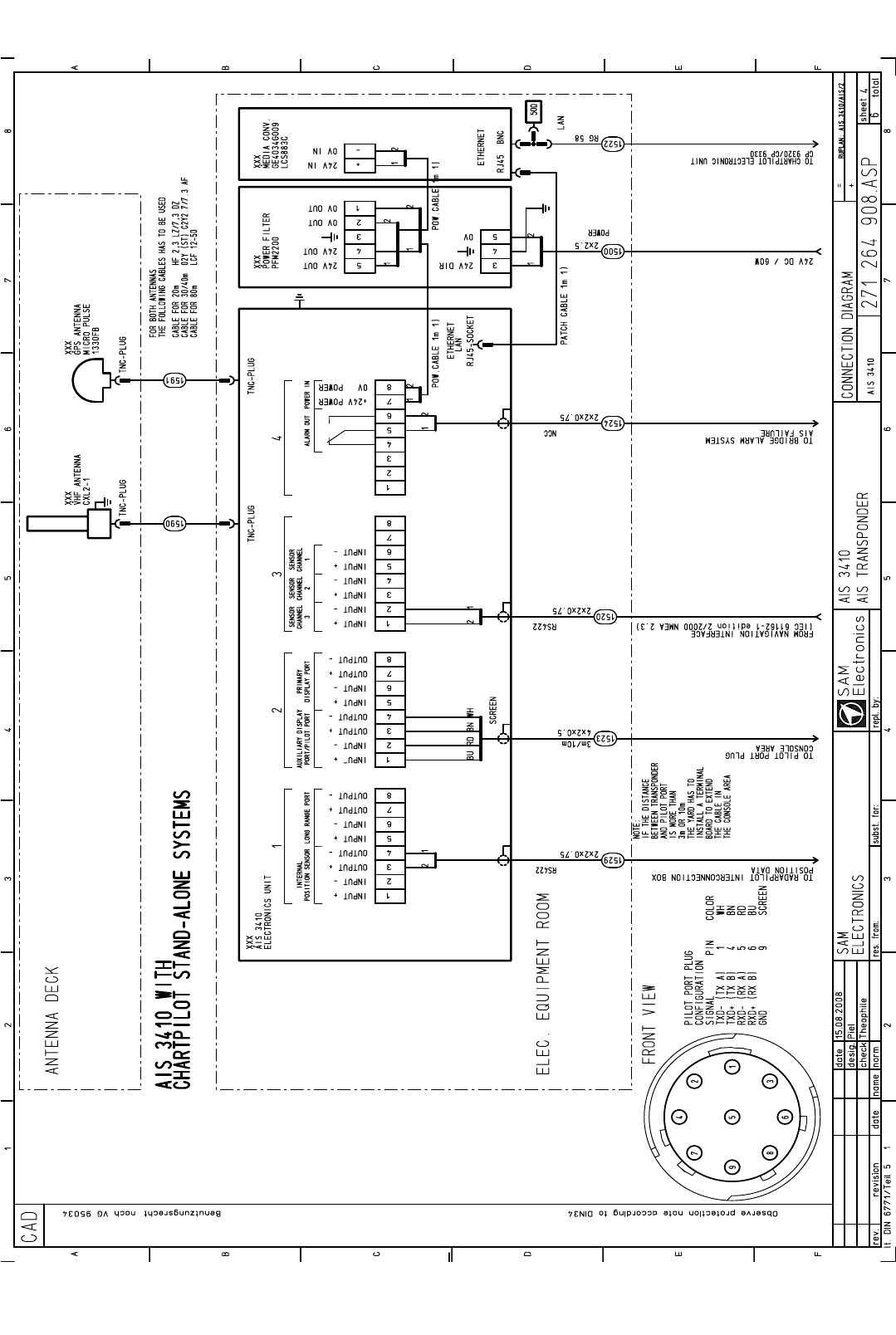
AIS 3410, Electronics Unit
ED3047G842 / 01 (2009-08)
Technical Manual
9 Cabling Documents
t_ue_e11.fm / 27.08.09
75
Fig. 9-8 Detailed Cable Diagram, connection to CHARTPILOT stand-alone systems
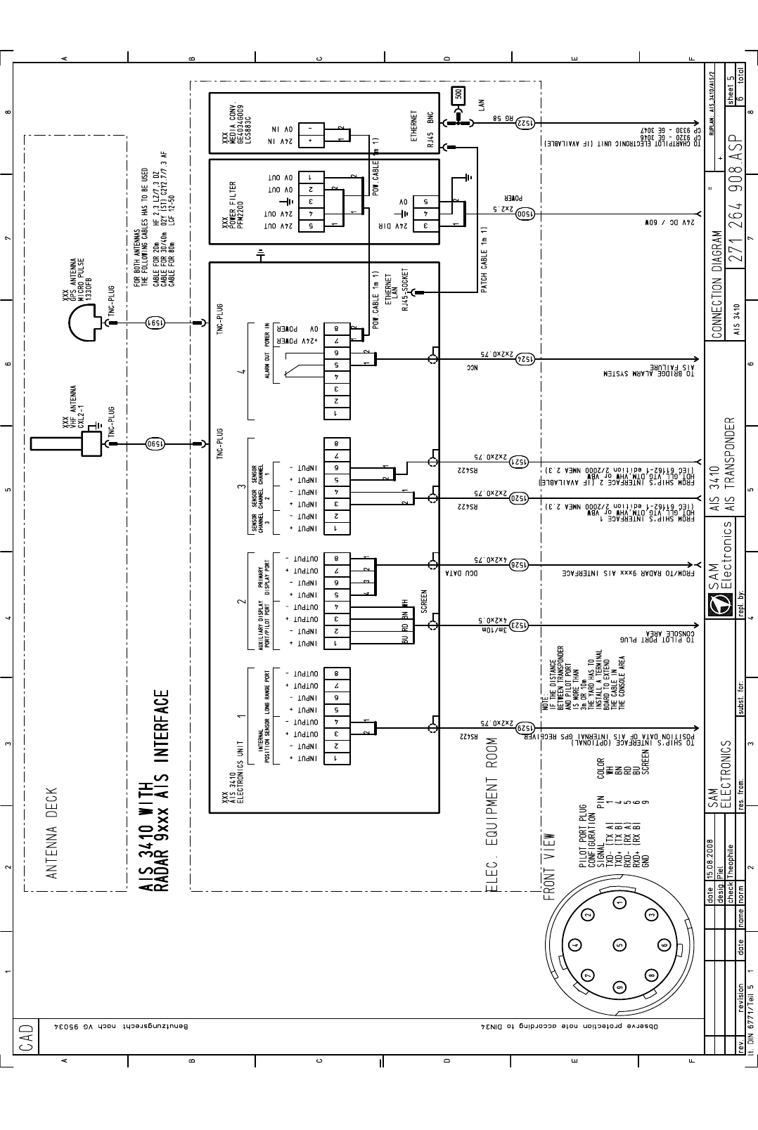
AIS 3410, Electronics Unit
ED3047G842 / 01 (2009-08)
Technical Manual
9 Cabling Documents
t_ue_e11.fm / 27.08.09
76
Fig. 9-9 Detailed Cable Diagram, connection to RADAR 9xxx AIS Interface
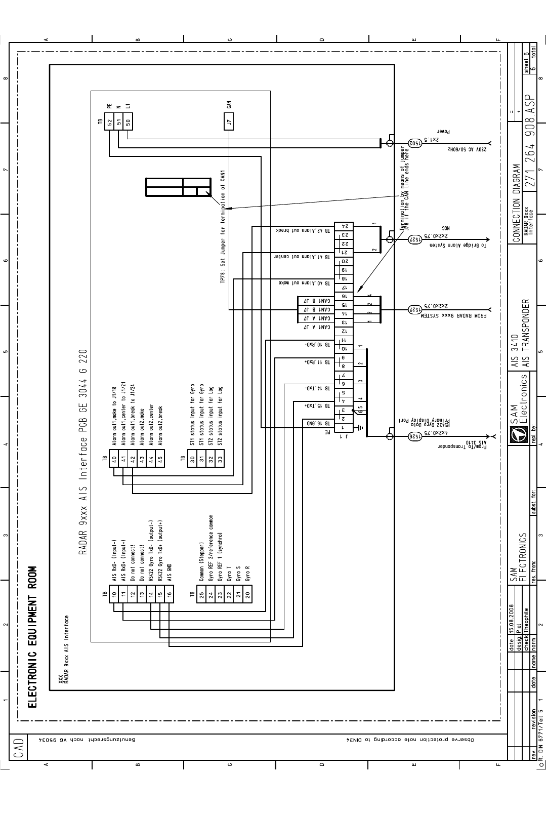
AIS 3410, Electronics Unit
ED3047G842 / 01 (2009-08)
Technical Manual
9 Cabling Documents
t_ue_e11.fm / 27.08.09
77
Fig. 9-10 Detailed Cable Diagram, connection to RADAR 9xxx AIS Interface PCB GE 3044 G 220

AIS 3410, Electronics Unit
ED3047G842 / 01 (2009-08)
Technical Manual
9 Cabling Documents
t_ue_e11.fm / 27.08.09
78
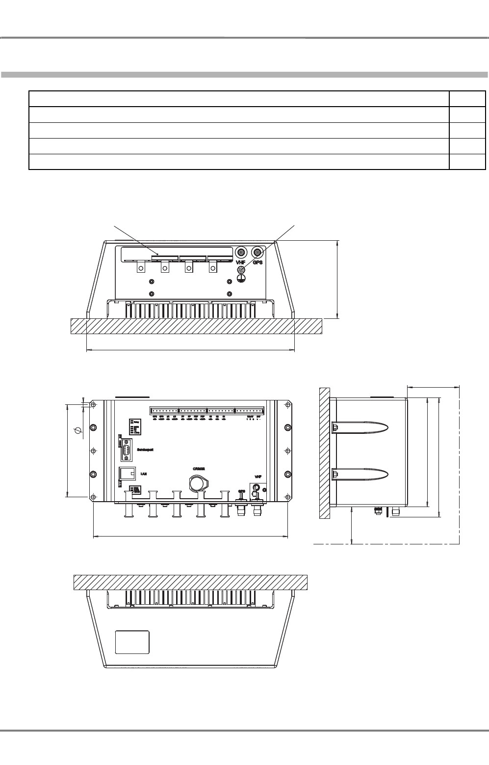
AIS 3410, Electronics Unit
ED3047G842 / 01 (2009-08)
Technical Manual
10 Outline Drawings
t_ue_e12.fm / 27.08.09
79
10 Outline Drawings
Fig. 10-1 AIS 3410 Outline Drawing
Title Page
AIS 3410 Outline Drawing
79
AIS GPS antenna, 1/2
80
AIS GPS antenna, 2/2
81
AIS VHF antenna
82
120
ca. 200
ca. 700
Area for cable inlet Grounding M6
320
Space required for service
168
184
Cover not shown
142
6,5
300
Weight: 3kg
Steering compass: 0.3 m
Protection category: IP22
Min. distance from:
Standard compass: 0.4 m
ONLY BULKHEAD MOUNTING
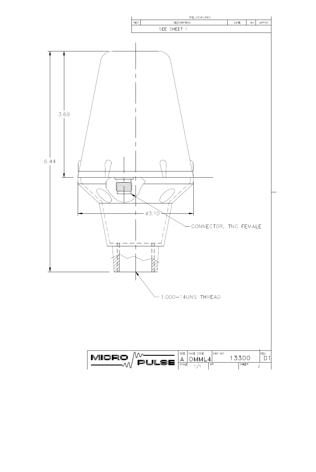
AIS 3410, Electronics Unit
ED3047G842 / 01 (2009-08)
Technical Manual
10 Outline Drawings
t_ue_e12.fm / 27.08.09
80
Fig. 10-2 AIS GPS antenna, 1/2
A
ll dimensions are indicated as inches.
z_ue_402.pdf
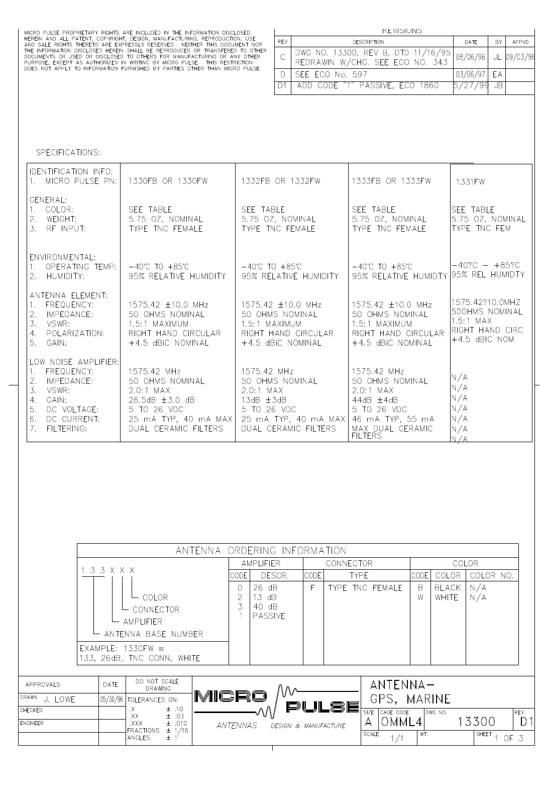
AIS 3410, Electronics Unit
ED3047G842 / 01 (2009-08)
Technical Manual
10 Outline Drawings
t_ue_e12.fm / 27.08.09
81
Fig. 10-3 AIS GPS antenna, 2/2
z_ue_403.pdf

AIS 3410, Electronics Unit
ED3047G842 / 01 (2009-08)
Technical Manual
10 Outline Drawings
t_ue_e12.fm / 27.08.09
82
Fig. 10-4 AIS VHF antenna

AIS 3410, Electronics Unit
ED3047G842 / 01 (2009-08)
Technical Manual
Notes
t_ue_eno.fm / 27.08.09
83
Notes
Space for your notes.

AIS 3410, Electronics Unit
ED3047G842 / 01 (2009-08)
Technical Manual
Notes
t_ue_eno.fm / 27.08.09
84