SAMYUNG ENC SMR-3700 LCD Color Marine Radar System User Manual 7
SAMYUNG ENC Co., Ltd LCD Color Marine Radar System 7
UserManual.wiki
>
SAMYUNG ENC
>
SMR 3700 User Manual
Users Manual
Navigation menu
Upload a User Manual
Namespaces
Wiki Guide
HTML
PDF
Info
Views
User Manual
Discussion / Help
Navigation
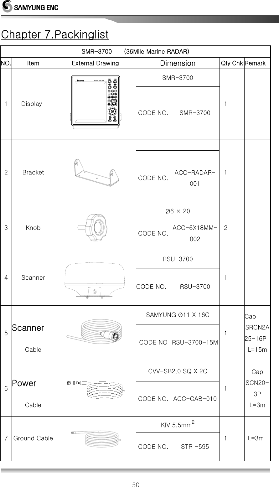
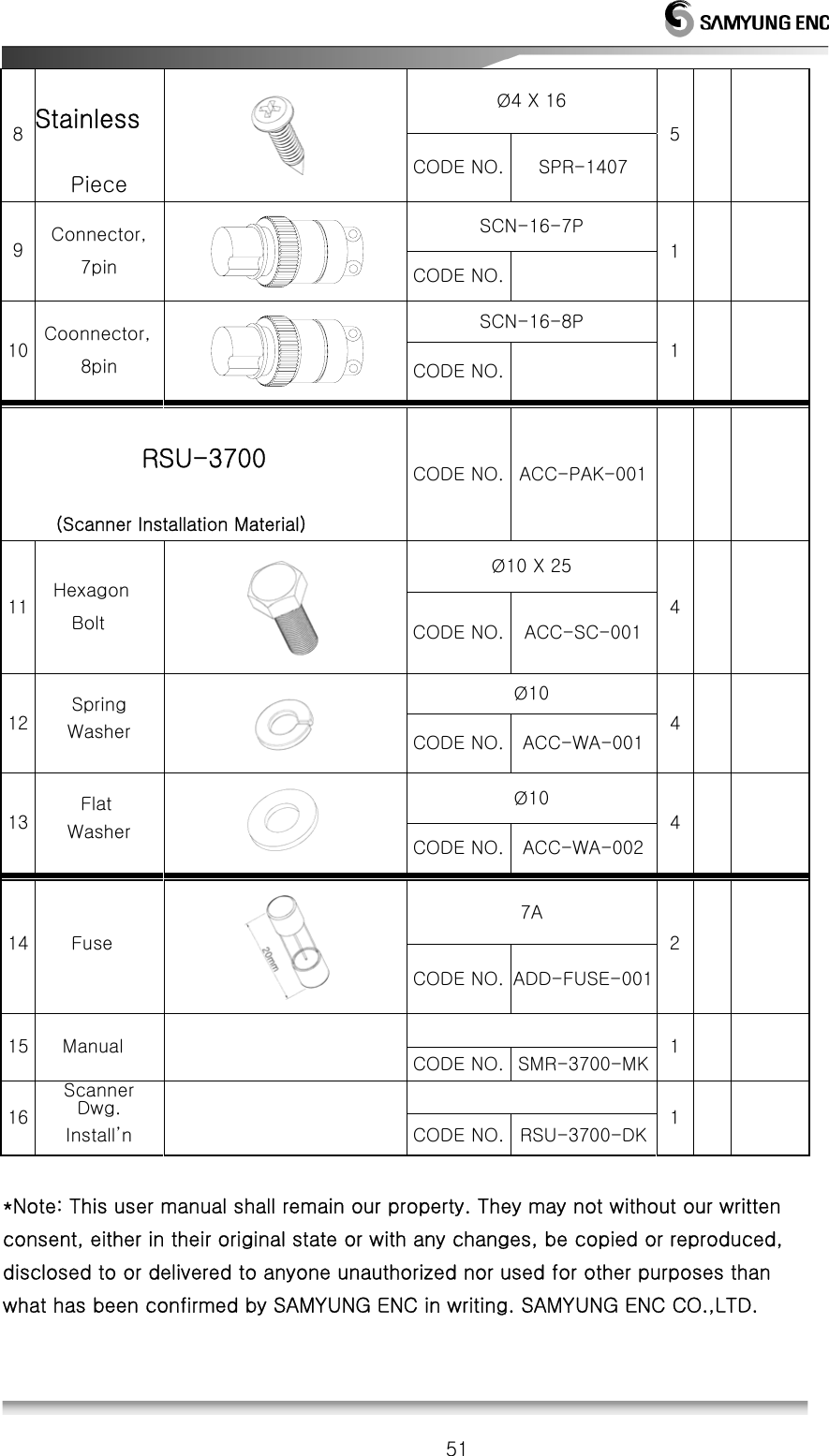
![5 Components Description Q’y Samyung CODE Remark Manual 1 SMR-3700-MK SCANNER-DISPLAY CABLE 1 RSU-3700-15M 15m POWER CABLE 1 ACC-CAB-010 3m SURGE CABLE 1 STR-595 3m 1.4 Construction 1504-M 1015020600274 [Pic. 1.1] RSU-3700 External Diagram](https://usermanual.wiki/SAMYUNG-ENC/SMR-3700/User-Guide-2036113-Page-5.png)
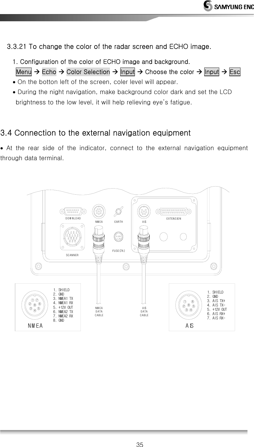
![6 140138 138SCANNER265133 133258POW ERDOW NLOADNMEAFUSE(7A)EARTH AISEXTENSIO N67322303307293 254-M 6194[Pic.1.2] SMR-3700 External diagram of Display](https://usermanual.wiki/SAMYUNG-ENC/SMR-3700/User-Guide-2036113-Page-6.png)
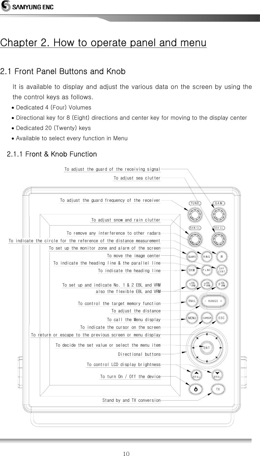
![11[Picture 2-1] Front Knob & othe Fron Button 2.1.2 Directional Key Tey are used to move the cursor, turn the EBL, change the VRM size and move to any of the sub-menu. They are used to operate the following functions. To set up the center movement pointTo set up the distance & bearing between parallel linesTo set up the alarm zoneTo move to the sub-menuTo set up EBL/VRMMENU2VRMEBLFVRMEBLTo move the cursorCENTOFF1EBLVRM Following is how to operate the exclusive keys. 2.1.3 Display Description Description Position Display Characters ALARM Right, Top ALM1, ALM2 Interferance Right, Top IR0, IR1, IR2 Sector Blank Right, Top BLANK Auto Tunning Right, Top TUNE AUTO Manual Tunning Right, Top TUNE MAN Target Zoom-In Left, Top EXT1, EXT2 Waypoint Memory Left, Top W1, W2, W3, W4 Heading Display Mode Left, Top H-UP, N-UP, C-UP Screen Zoom-In Left, Top ZOOM Heading Bearing Middle, Top HDG Gain Middle, Bottom GAIN Rain & Snow Clearing Middle, Bottom RAIN CL Sea Clutter Clearing Middle, Bottom SEA CL Auto Gain Right, Bottom GAIN-A Auto Rain & Snow Clearing Right, Bottom RAIN-A Auto Sea Clutter Clearing Right, Bottom SEA-A](https://usermanual.wiki/SAMYUNG-ENC/SMR-3700/User-Guide-2036113-Page-11.png)
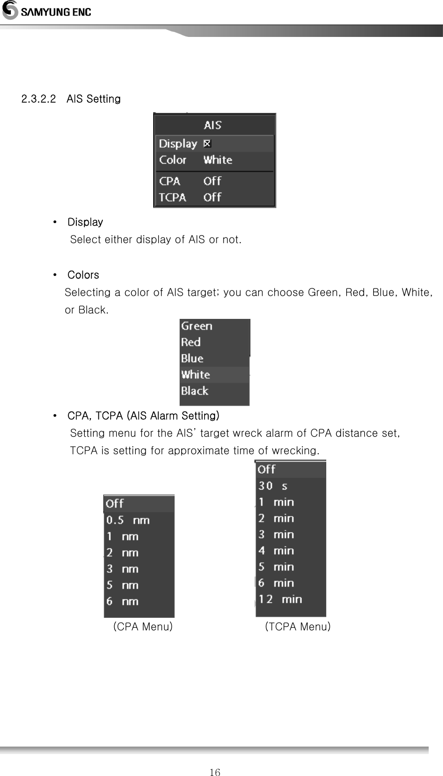
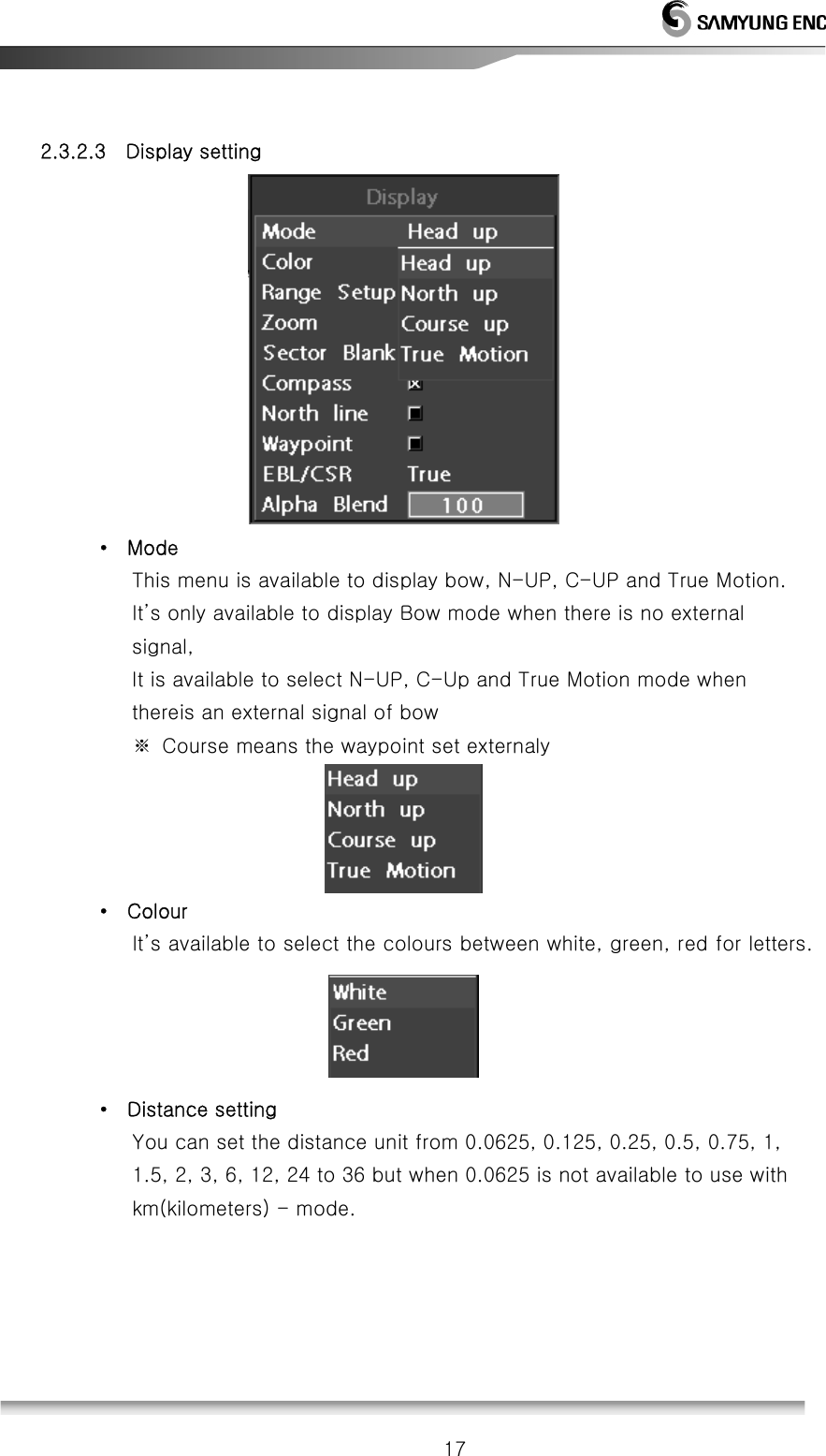
![13 2.3 Menu Functions In addition to the functions used by the front panel keys, SMR-3700 has the functions to enable user to control with menu. 2.3.1 Menu Composition It is available to converse the display language to Korean, English and other languages. Press MENU and select any wishful setup menu by using direction button. There are total of five (5) different menus and each menu function explained as following; ◎ Echo Menu : Menu setting for the target display ◎ AIS Menu : Menu setting for the AIS display ◎ Display Menu : Menu setting for the display colors and other functions. ◎ Comms (Communication) Menu : Menu setting for external devices and communication speed or usage. ◎ System Menu : Sets languages and equipment’s initial setting menu [Echo Menu] [AIS Menu]](https://usermanual.wiki/SAMYUNG-ENC/SMR-3700/User-Guide-2036113-Page-13.png)
![14 [Display Menu] [Communication Menu] [System Menu] [Initial Display]](https://usermanual.wiki/SAMYUNG-ENC/SMR-3700/User-Guide-2036113-Page-14.png)
![21 Chapter 3. How to operate the unit 3.1 General Idea 3.1.1 Power input and Operation 1. Power input • To power on, press POWER button. • Afte power on, Count Down Timer is displayed on SAMYUNG Logo screen, it is converted to the stand-by in 1 min. 30 secs. • As the TX time is consolidated and displayed, user can judge the ideal time for repair.. • It indicates the version of the program.. [Refer] When it is not available to power off due to programme is down, please push OFF switch for 10 seconds so that you can turn it off by force. 2. TX • Press button to enable the transmission at the stand-by status.. • Press button again to convert the TX status to the stand-by status. 3.1.2 Tuning control It is required to control the tuning of the unit both manually and automatically. The conversion is selectable in the setup of MENU. For the automatica tuning,“Auto Tuning” is displayed next to the tuning bar. 1. Change tuning mode • Menu Æ System Æ Tuning Æ Auto / Manual Æ Input Æ Return 2. Control tuning volume • In case of tha manual tuning mode, turn the volume to adjust the image biggest. • Adjust the movement of the tuning bar biggest.. • In case of the automatic tuning mode, it is needless to turn the volume. • If any image doesn’t appear, adjust the volume again or turn the volume of / (rain/snow) removal. 3.1.3 Image control the volume of the tuning/gain of (sea clutter), (rain/snow), removal to display the optimum image.](https://usermanual.wiki/SAMYUNG-ENC/SMR-3700/User-Guide-2036113-Page-21.png)
![22 3.1.4 Power off 1. Stop transmission(TX). • Push T X key to be ready to transmit . 2. Turn off the Power. • Push POWER key for 3 seconds then power will be turned off. ex) The parts for power on are operating while power is offed so please disconnect power completely if you don’t use this equipment for long. 3.2 Stand by for processing 3.2.1 Brightness change • Press brightness key. Push ▲ key to brighten the screen, push ▼ key to darken the screen. There are 10 levels you can adjust. 3.2.2 Language Selection • Menu Æ Æ System Æ Languange Æ Select user’s language Æ Input Æ Return Select language what user wants to use. 3.3 Basic Operation 3.3.1 TX • Press T X button, it will be converted to TX from the stand-by status. 3.3.2 TX Stop • Press T X button again at the TX, it will be the stand-by status. 3.3.3 Tuning Control • Please refer to [3.1.2 Tuning Control].](https://usermanual.wiki/SAMYUNG-ENC/SMR-3700/User-Guide-2036113-Page-22.png)
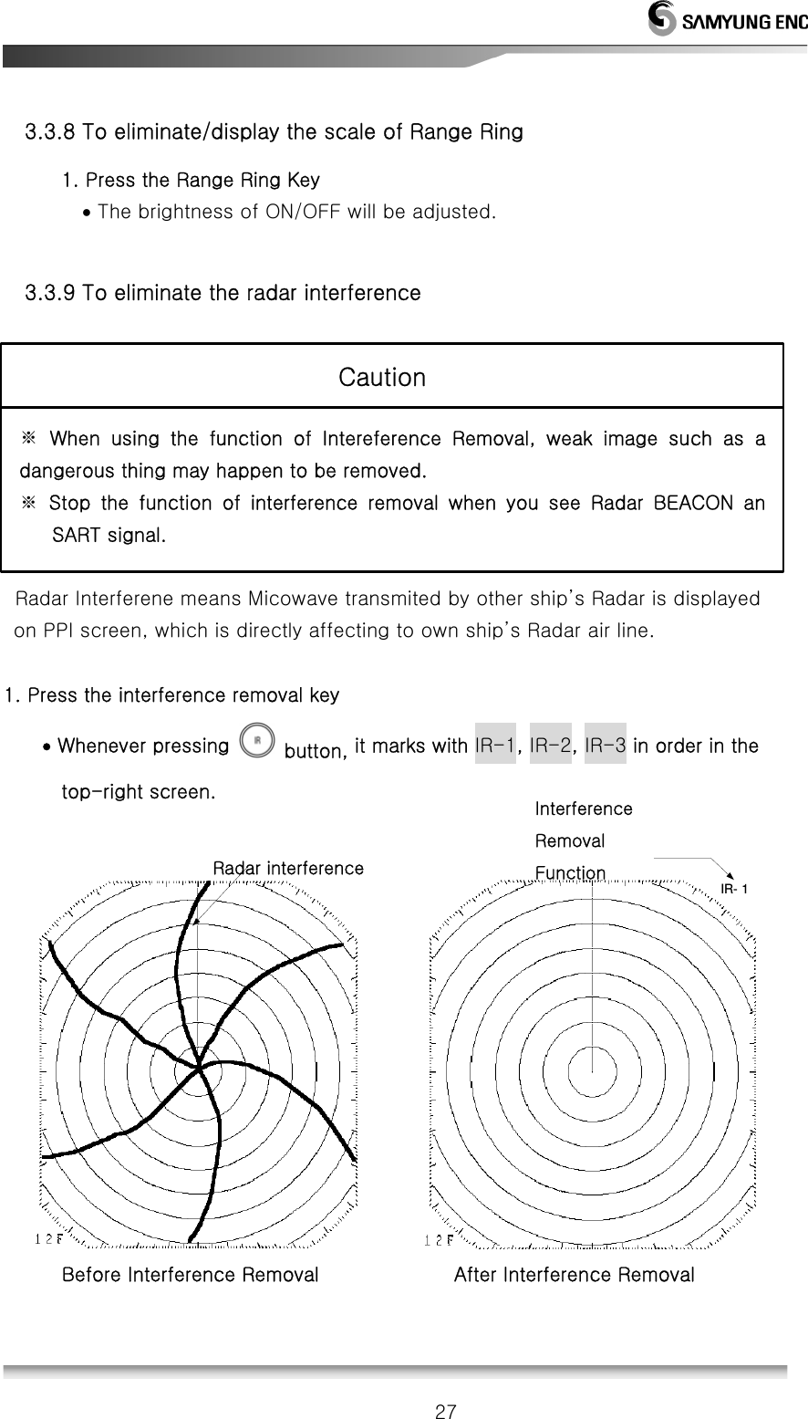
![26 3.3.7 To operate the alert function • Set the guide zone in order to use the alert. • Guard Zone means [Zone] to be set on PPI screen 1. Guard Zone Setting • Locate the cursor where you want to move • Press the Alert key • POP-UP Menu will be appeared to set up two different guide zones on the screen • Select incursion or separation of guide zone. • Incursion means the target enters into the zone and sepatation means the target come out of the zone. In each case, the alert sound will come outt • Select Ring or Fan Ring function will create ring-shaped guide zone and Fan function will create Fan-shaped guide zone. • Press Adjust and then move the cursor to set up the guide zone. • Press the input key. • After a desired guide zone is done then exit 2. Occurrence and Stoppage of the alert sound • After setting up the guide zone, the alert sound will come out once the target enther into the zone. • To stop the alert sound, press any key on the device. 3. Termination of the alert • To terminate the alert status, press the alert key and then select the alert zone off.](https://usermanual.wiki/SAMYUNG-ENC/SMR-3700/User-Guide-2036113-Page-26.png)
![29 3. Measurement of the distance and bearing by using F EBL/VRM • Press the F EBL/VRM key. • EBL/VRM will appear on the radar screen. • Once the cursor is appeared, move to the desired position. • By pressing Center Movement key, the center of F EBL/VRM will be shifted and will be back to the original position by repressing the key. • By pressing cursor, cursor will be disappeared and then use the direction key to move EBL/VRM to the desired position. • The value of distance and bearing will appear on the bottom end of the screen.. • To exit, press the esc key. [Ref] F EBL/VRM can be used to indicate EBL/VRM on the specified position. 4. Measurement of the distance and bearing by using Cursor • By using Cursor, cross shaped cursor will be appeared on the radar screen. • The value of distance and bearing will appear at the bottom end of the screen,where the cursor is located. 3.3.14 To change the distance uni 1. NM (Nautical Mile) Menu Æ System Æ Distance unit Æ Input Æ NM Æ Input Æ Esc • Cursor, VRM, Distance of parallel line represents NM. 2. Mile Menu Æ Sytem Æ Distance unit Æ Input Æ Mi Æ Input Æ Esc • Cursor, VRM, Distance of parallel line represents Mi 3. Kilometer (Km) Menu Æ System Æ Distance unit Æ Input Æ KM Æ Input Æ Esc • Cursor, VRM, Distance of parallel line represents KM.](https://usermanual.wiki/SAMYUNG-ENC/SMR-3700/User-Guide-2036113-Page-29.png)
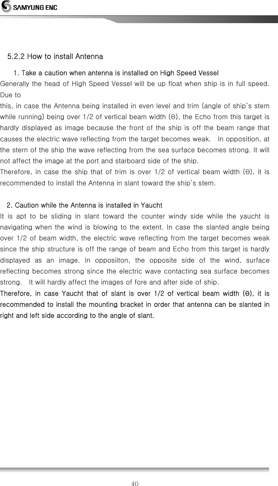
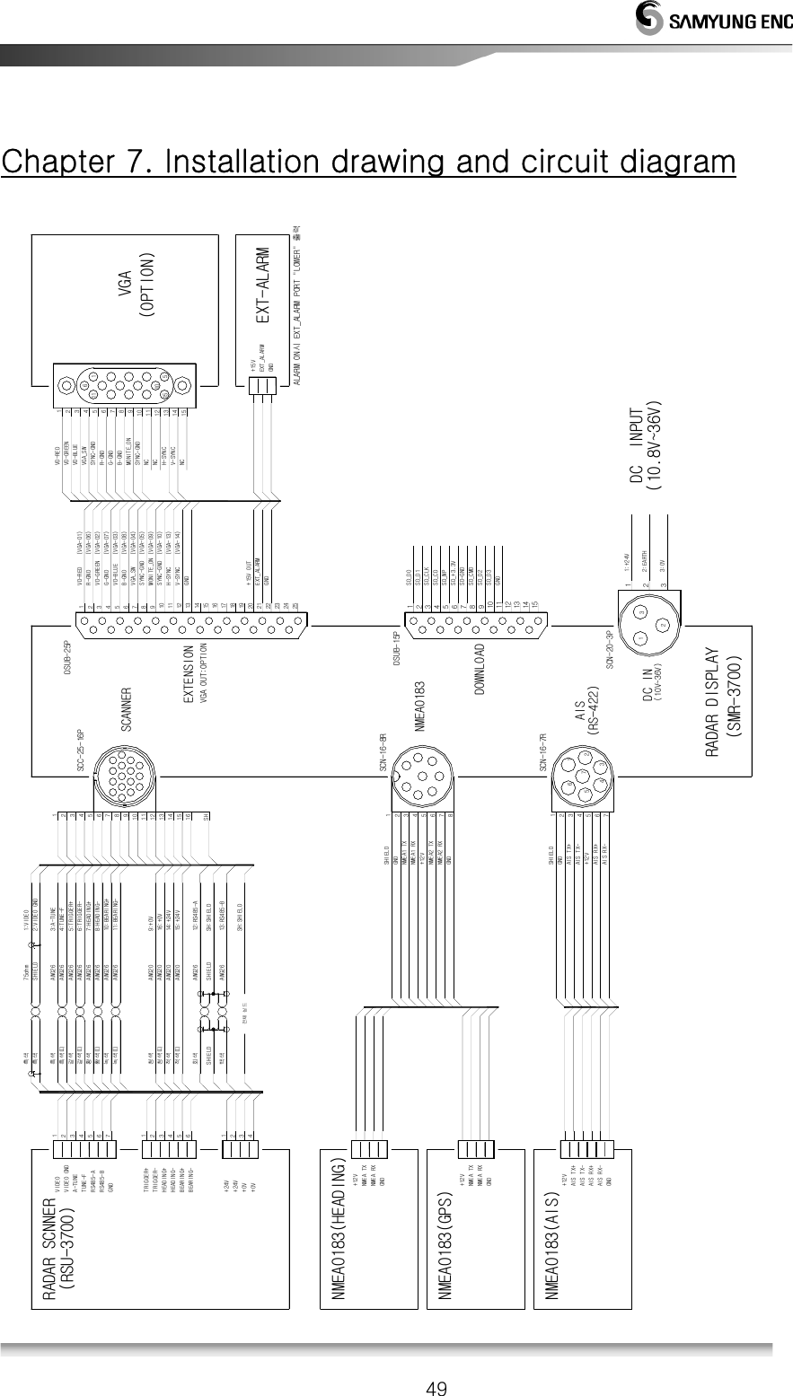
![43 5.3. DISPLAY SET-UP 5.3.1. Location for installation • Select the location for easy-investigation and maintenance. 5.3.2 How to Install (1) Install the display according to the Block Diagram. (2) Refer to the installation diagram. 5.3.3. Power Cable connection (1) Connect a Power cable to [POWER] of the back-pannel. (2) Connect an Aireal-cable to [SCANNER] of the back-pannel. (3) Connect an earth cable to [EARTH] of the back-pannel. 5.4. Installation check • After installation, check weather the condition is O.K based on the instruction. The serious check points are the cable connection, tight connection of each units, aireal-cable, the connection of cable shield. 5.5. Operation check (1) Before the operation check, it needs to check if the internal voltage is in an acceptable voltage range. (2) Check all parts of the radar in detail after operation check. (3) Readjustment should be according to the manual even though the operation check is O.K. ※ A display must be installed far away over than 1 meter from a magnet compass. ※ It may be harmful to the magnet compass in case of closer installation. ATTENTION](https://usermanual.wiki/SAMYUNG-ENC/SMR-3700/User-Guide-2036113-Page-43.png)
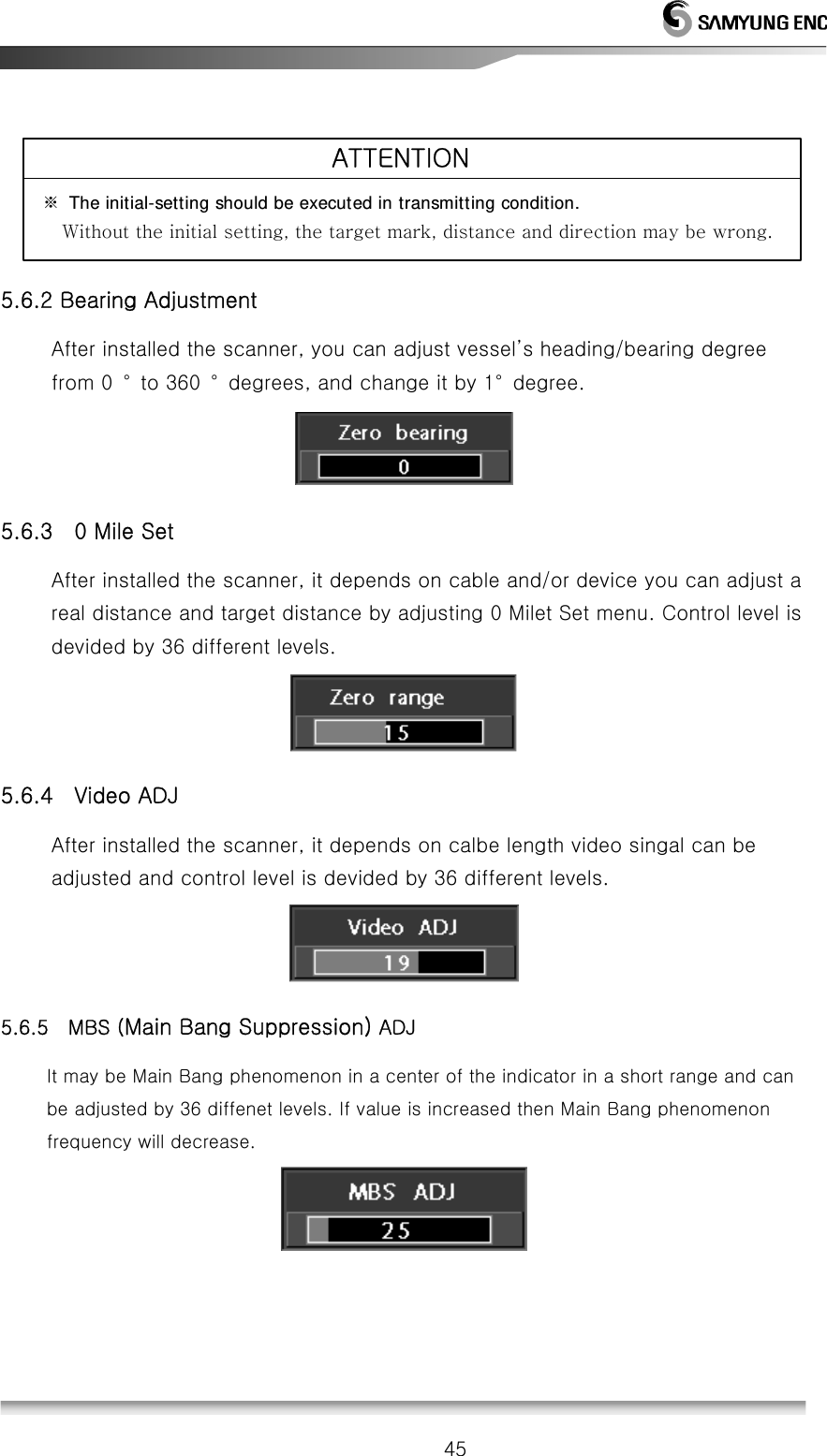
![44 5.6. Initial Installation • In case of a first time, it must be executed an initial adjustment. 5.6.1 Initial Installation Following is how to go to Initial setup menu Menu Æ SystemÆ Int. Set Æ Enter after press these keys will show following display. ※ Installation menu activate procdure: At Menu in System list, press Cursor 중심이동 Cursor 중심이동 keys within 5 seconds then following screen will show: [Screen before activation of installation menu] [Screen after activation of installation menu]](https://usermanual.wiki/SAMYUNG-ENC/SMR-3700/User-Guide-2036113-Page-44.png)
![46!5.6.6 Tune ADJ On the front, there is key control knob for Tunning and can be adjusted by 64 different levels. For setting procudre, make Tune VR to the center and set target object and Tune knob to the maximum. 5.6.7 MT-RPM ADJ This is how to set for the scanner’s motor RPM. Motor rotartion will display with RPM measurement, normal operatiing rotate per minute is 24 RPM. ATTENTION) When you operating in high speed then targeting object accuracy will decrease and system speed can be decrease. 5.6.8 Software Upgrade This menu will upgrade previouse software program. 5.6.9 Default manufacturing Setting This menu will reset the default manufacturing settings. ATTENTION) This menu is limited to use by end-users. 5.6.10 Default basic manufactreing set-up This menu will reset devise to basic set up from the manufacuter. ] ATTENTIODevice came out with fully adjusted. For resetting for default basic manufacture is limited to end-users. Not recomannding for adjusted by end-users all the time.](https://usermanual.wiki/SAMYUNG-ENC/SMR-3700/User-Guide-2036113-Page-46.png)