SAMYUNG ENC SMR-3700 LCD Color Marine Radar System User Manual 7
SAMYUNG ENC Co., Ltd LCD Color Marine Radar System 7
Users Manual

1
Contents
Chapter 1. Overview
1.1 Function ∙∙∙∙∙∙∙∙∙∙∙∙∙∙∙∙∙∙∙∙∙∙∙∙∙∙∙∙∙∙∙∙∙∙∙∙∙∙∙∙∙∙∙∙∙∙∙∙∙∙∙∙∙∙∙∙∙∙∙∙∙∙∙∙∙∙∙∙∙∙∙∙∙∙∙∙∙∙∙∙∙∙∙∙∙∙∙∙∙∙∙∙∙∙∙∙∙∙∙∙∙∙∙∙∙∙∙∙∙∙∙∙∙ 4
1.2 Feature ∙∙∙∙∙∙∙∙∙∙∙∙∙∙∙∙∙∙∙∙∙∙∙∙∙∙∙∙∙∙∙∙∙∙∙∙∙∙∙∙∙∙∙∙∙∙∙∙∙∙∙∙∙∙∙∙∙∙∙∙∙∙∙∙∙∙∙∙∙∙∙∙∙∙∙∙∙∙∙∙∙∙∙∙∙∙∙∙∙∙∙∙∙∙∙∙∙∙∙∙∙∙∙∙∙∙∙∙∙∙∙∙∙ 4
1.3 Composition ∙∙∙∙∙∙∙∙∙∙∙∙∙∙∙∙∙∙∙∙∙∙∙∙∙∙∙∙∙∙∙∙∙∙∙∙∙∙∙∙∙∙∙∙∙∙∙∙∙∙∙∙∙∙∙∙∙∙∙∙∙∙∙∙∙∙∙∙∙∙∙∙∙∙∙∙∙∙∙∙∙∙∙∙∙∙∙∙∙∙∙∙∙∙∙∙∙∙∙∙∙∙∙∙∙∙∙∙∙∙∙∙∙ 4
1.4 Construction ∙∙∙∙∙∙∙∙∙∙∙∙∙∙∙∙∙∙∙∙∙∙∙∙∙∙∙∙∙∙∙∙∙∙∙∙∙∙∙∙∙∙∙∙∙∙∙∙∙∙∙∙∙∙∙∙∙∙∙∙∙∙∙∙∙∙∙∙∙∙∙∙∙∙∙∙∙∙∙∙∙∙∙∙∙∙∙∙∙∙∙∙∙∙∙∙∙∙∙∙∙∙∙∙∙∙∙∙∙∙∙∙∙ 5
1.5 Specifications ∙∙∙∙∙∙∙∙∙∙∙∙∙∙∙∙∙∙∙∙∙∙∙∙∙∙∙∙∙∙∙∙∙∙∙∙∙∙∙∙∙∙∙∙∙∙∙∙∙∙∙∙∙∙∙∙∙∙∙∙∙∙∙∙∙∙∙∙∙∙∙∙∙∙∙∙∙∙∙∙∙∙∙∙∙∙∙∙∙∙∙∙∙∙∙∙∙∙∙∙∙∙∙∙∙∙∙∙∙∙∙∙∙ 7
1.5.1 General ∙∙∙∙∙∙∙∙∙∙∙∙∙∙∙∙∙∙∙∙∙∙∙∙∙∙∙∙∙∙∙∙∙∙∙∙∙∙∙∙∙∙∙∙∙∙∙∙∙∙∙∙∙∙∙∙∙∙∙∙∙∙∙∙∙∙∙∙∙∙∙∙∙∙∙∙∙∙∙∙∙∙∙∙∙∙∙∙∙∙∙∙∙∙∙ 7
1.5.2 Scanner (RSU-3700) ∙∙∙∙∙∙∙∙∙∙∙∙∙∙∙∙∙∙∙∙∙∙∙∙∙∙∙∙∙∙∙∙∙∙∙∙∙∙∙∙∙∙∙∙∙∙∙∙∙∙∙∙∙∙∙∙∙∙∙∙∙∙∙∙∙∙∙∙∙∙∙∙∙∙∙∙∙∙∙∙ 7
1.5.3 Display Unit (SMR-3700) ∙∙∙∙∙∙∙∙∙∙∙∙∙∙∙∙∙∙∙∙∙∙∙∙∙∙∙∙∙∙∙∙∙∙∙∙∙∙∙∙∙∙∙∙∙∙∙∙∙∙∙∙∙∙∙∙∙∙∙∙∙∙∙∙∙∙∙∙∙∙∙∙∙∙∙∙∙∙∙∙ 8
1.5.4 Connection Cable ∙∙∙∙∙∙∙∙∙∙∙∙∙∙∙∙∙∙∙∙∙∙∙∙∙∙∙∙∙∙∙∙∙∙∙∙∙∙∙∙∙∙∙∙∙∙∙∙∙∙∙∙∙∙∙∙∙∙∙∙∙∙∙∙∙∙∙∙∙∙∙∙∙∙∙∙∙∙∙∙∙∙∙∙∙∙∙∙∙∙∙∙∙ 9
Chapter 2. How to operate panel and menu
2.1 Front Panel Buttons and Knob ∙∙∙∙∙∙∙∙∙∙∙∙∙∙∙∙∙∙∙∙∙∙∙∙∙∙∙∙∙∙∙∙∙∙∙∙∙∙∙∙∙∙∙∙∙∙∙∙∙∙∙∙∙∙∙∙∙∙∙∙∙∙∙∙∙∙∙∙∙∙∙∙∙∙∙∙∙∙∙∙∙ 10
2.1.1 Front Function ∙∙∙∙∙∙∙∙∙∙∙∙∙∙∙∙∙∙∙∙∙∙∙∙∙∙∙∙∙∙∙∙∙∙∙∙∙∙∙∙∙∙∙∙∙∙∙∙∙∙∙∙∙∙∙∙∙∙∙∙∙∙∙∙∙∙∙∙∙∙∙∙∙∙∙∙∙∙∙∙∙∙∙ 10
2.1.2 Directional Key ∙∙∙∙∙∙∙∙∙∙∙∙∙∙∙∙∙∙∙∙∙∙∙∙∙∙∙∙∙∙∙∙∙∙∙∙∙∙∙∙∙∙∙∙∙∙∙∙∙∙∙∙∙∙∙∙∙∙∙∙∙∙∙∙∙∙∙∙∙∙∙∙∙∙∙∙∙∙∙ 11
2.1.3 Display Characters ∙∙∙∙∙∙∙∙∙∙∙∙∙∙∙∙∙∙∙∙∙∙∙∙∙∙∙∙∙∙∙∙∙∙∙∙∙∙∙∙∙∙∙∙∙∙∙∙∙∙∙∙∙∙∙∙∙∙∙∙∙∙∙∙∙∙∙∙∙∙∙∙∙∙∙∙∙∙∙∙∙∙∙∙∙∙∙ 11
2.2. Display Description ∙∙∙∙∙∙∙∙∙∙∙∙∙∙∙∙∙∙∙∙∙∙∙∙∙∙∙∙∙∙∙∙∙∙∙∙∙∙∙∙∙∙∙∙∙∙∙∙∙∙∙∙∙∙∙∙∙∙∙∙∙∙∙∙∙∙∙∙∙∙∙∙∙∙∙∙∙∙∙∙∙∙∙∙∙∙∙∙∙∙∙∙∙∙∙∙∙∙∙∙∙∙∙ 12
2.3. Menu Functions ∙∙∙∙∙∙∙∙∙∙∙∙∙∙∙∙∙∙∙∙∙∙∙∙∙∙∙∙∙∙∙∙∙∙∙∙∙∙∙∙∙∙∙∙∙∙∙∙∙∙∙∙∙∙∙∙∙∙∙∙∙∙∙∙∙∙∙∙∙∙∙∙∙∙∙∙∙∙∙∙∙∙∙ 13
2.3.1 Menu Composition ∙∙∙∙∙∙∙∙∙∙∙∙∙∙∙∙∙∙∙∙∙∙∙∙∙∙∙∙∙∙∙∙∙∙∙∙∙∙∙∙∙∙∙∙∙∙∙∙∙∙∙∙∙∙∙∙∙∙∙∙∙∙∙∙∙∙∙∙∙∙∙∙∙∙∙∙∙∙∙∙∙∙∙∙∙∙∙∙∙∙∙∙∙∙∙ 13
2.3.2 MENU Functions ∙∙∙∙∙∙∙∙∙∙∙∙∙∙∙∙∙∙∙∙∙∙∙∙∙∙∙∙∙∙∙∙∙∙∙∙∙∙∙∙∙∙∙∙∙∙∙∙∙∙∙∙∙∙∙∙∙∙∙∙∙∙∙∙∙∙∙∙∙∙∙∙∙∙∙∙∙∙∙∙∙∙∙∙∙∙∙∙∙ 16
Chapter 3.
How to operate the unit
3.1 General Idea ∙∙∙∙∙∙∙∙∙∙∙∙∙∙∙∙∙∙∙∙∙∙∙∙∙∙∙∙∙∙∙∙∙∙∙∙∙∙∙∙∙∙∙∙∙∙∙∙∙∙∙∙∙∙∙∙∙∙∙∙∙∙∙∙∙∙∙∙∙∙∙∙∙∙∙∙∙∙∙∙∙∙∙∙∙∙∙∙∙∙∙∙∙∙∙∙∙∙∙∙∙∙∙ 21
3.1.1 Power Input and Operation ∙∙∙∙∙∙∙∙∙∙∙∙∙∙∙∙∙∙∙∙∙∙∙∙∙∙∙∙∙∙∙∙∙∙∙∙∙∙∙∙∙∙∙∙∙∙∙∙∙∙∙∙∙∙∙∙∙∙∙∙∙∙∙∙∙∙∙∙∙∙∙∙∙∙∙∙∙∙∙∙∙ 21
3.1.2 Tuning Control ∙∙∙∙∙∙∙∙∙∙∙∙∙∙∙∙∙∙∙∙∙∙∙∙∙∙∙∙∙∙∙∙∙∙∙∙∙∙∙∙∙∙∙∙∙∙∙∙∙∙∙∙∙∙∙∙∙∙∙∙∙∙∙∙∙∙∙∙∙∙∙∙∙∙∙∙∙∙∙∙∙∙∙∙∙∙∙∙∙∙∙∙∙∙∙ 21
3.1.3 Image Control ∙∙∙∙∙∙∙∙∙∙∙∙∙∙∙∙∙∙∙∙∙∙∙∙∙∙∙∙∙∙∙∙∙∙∙∙∙∙∙∙∙∙∙∙∙∙∙∙∙∙∙∙∙∙∙∙∙∙∙∙∙∙∙∙∙∙∙∙∙∙∙∙∙∙∙∙∙∙∙∙∙∙∙∙∙∙∙∙∙∙∙∙∙∙∙ 21
3.1.4 Power Off ∙∙∙∙∙∙∙∙∙∙∙∙∙∙∙∙∙∙∙∙∙∙∙∙∙∙∙∙∙∙∙∙∙∙∙∙∙∙∙∙∙∙∙∙∙∙∙∙∙∙∙∙∙∙∙∙∙∙∙∙∙∙∙∙∙∙∙∙∙∙∙∙∙∙∙∙∙∙∙∙∙ 22
3.2 Stand-by for Processing∙∙∙∙∙∙∙∙∙∙∙∙∙∙∙∙∙∙∙∙∙∙∙∙∙∙∙∙∙∙∙∙∙∙∙∙∙∙∙ 22
3.2.1 Brightness Change ∙∙∙∙∙∙∙∙∙∙∙∙∙∙∙∙∙∙∙∙∙∙∙∙∙∙∙∙∙∙∙∙∙∙∙∙∙∙∙∙∙∙∙∙∙∙∙∙∙∙∙∙∙∙∙ 22
3.2.2 Language Selection ∙∙∙∙∙∙∙∙∙∙∙∙∙∙∙∙∙∙∙∙∙∙∙∙∙∙∙∙∙∙∙∙∙∙∙∙∙∙∙∙∙∙∙∙∙∙∙∙∙∙∙∙∙∙∙∙∙∙∙∙∙∙∙∙∙∙∙∙∙ 22
3.3 Basic Operation ∙∙∙∙∙∙∙∙∙∙∙∙∙∙∙∙∙∙∙∙∙∙∙∙∙∙∙∙∙∙∙∙∙∙∙∙∙∙∙∙∙∙∙∙∙∙∙∙∙∙∙∙∙∙∙∙∙∙∙∙∙∙∙∙∙∙∙∙∙∙∙∙∙∙∙∙∙∙∙∙∙∙∙∙∙∙∙∙∙∙∙∙∙∙∙∙∙∙∙∙∙∙∙∙∙∙∙ 22
3.3.1 TX ∙∙∙∙∙∙∙∙∙∙∙∙∙∙∙∙∙∙∙∙∙∙∙∙∙∙∙∙∙∙∙∙∙∙∙∙∙∙∙∙∙∙∙∙∙∙∙∙∙∙∙∙∙∙∙∙∙∙∙∙∙∙∙∙∙∙∙∙∙∙∙∙∙∙∙∙∙∙∙∙∙∙∙ 22
3.3.2 TX Stop ∙∙∙∙∙∙∙∙∙∙∙∙∙∙∙∙∙∙∙∙∙∙∙∙∙∙∙∙∙∙∙∙∙∙∙∙∙∙∙∙∙∙∙∙∙∙∙∙∙∙∙∙∙∙∙∙∙∙∙∙∙∙∙∙∙∙∙∙∙ 22
3.3.3 Tuning Control ∙∙∙∙∙∙∙∙∙∙∙∙∙∙∙∙∙∙∙∙∙∙∙∙∙∙∙∙∙∙∙∙∙∙∙∙∙∙∙∙∙∙∙∙∙∙∙∙∙∙∙∙∙∙∙∙∙∙∙∙∙∙∙∙∙∙∙∙∙ 22

2
3.3.4 Gain Control ∙∙∙∙∙∙∙∙∙∙∙∙∙∙∙∙∙∙∙∙∙∙∙∙∙∙∙∙∙∙∙∙∙∙∙∙∙∙∙∙∙∙∙∙∙∙∙∙∙∙∙∙∙∙∙∙∙∙∙∙∙∙∙∙∙∙∙ 23
3.3.5 Rain/Snow Removal ∙∙∙∙∙∙∙∙∙∙∙∙∙∙∙∙∙∙∙∙∙∙∙∙∙∙∙∙∙∙∙∙∙∙∙∙∙∙∙∙∙∙ 24
3.3.6
To remove the interference of Sea Level Wave caused by the Sea Wave
∙∙∙∙∙∙∙∙∙∙∙∙ 25
3.3.7 To operate the alert function ∙∙∙∙∙∙∙∙∙∙∙∙∙∙∙∙∙∙∙∙∙∙∙∙∙∙∙∙∙∙∙∙∙∙∙∙∙∙∙∙∙∙∙∙∙∙∙∙∙∙∙∙∙∙∙∙∙∙∙ 26
3.3.8 To eliminate/display the scale of Range Ring ∙∙∙∙∙∙∙∙∙∙∙∙∙∙∙∙∙∙∙∙∙∙∙∙∙∙∙∙∙∙∙∙∙∙∙∙∙∙∙∙∙∙∙∙∙∙ 26
3.3.9 To remove the Radar Interference ∙∙∙∙∙∙∙∙∙∙∙∙∙∙∙∙∙∙∙∙∙∙∙∙∙∙∙∙∙∙∙∙∙∙∙∙∙∙∙∙∙∙∙∙∙∙∙∙∙∙∙∙∙∙∙∙∙ 27
3.3.10 To eleminate the Ship’s Heading Line ∙∙∙∙∙∙∙∙∙∙∙∙∙∙∙∙∙∙∙∙∙∙∙∙∙∙∙∙∙∙∙∙∙∙∙∙∙∙∙∙∙∙∙∙∙∙∙∙∙∙∙∙∙∙∙∙∙∙∙∙∙ 27
3.3.11 To use the parallel line ∙∙∙∙∙∙∙∙∙∙∙∙∙∙∙∙∙∙∙∙∙∙∙∙∙∙∙∙∙∙∙∙∙∙∙∙∙∙∙∙∙∙∙∙∙∙∙∙∙∙∙∙∙∙∙∙∙∙∙∙∙∙∙ 28
3.3.12 To move the center of own ship ∙∙∙∙∙∙∙∙∙∙∙∙∙∙∙∙∙∙∙∙∙∙∙∙∙∙∙∙∙∙∙∙∙∙∙∙∙∙∙∙∙∙∙∙∙∙∙∙∙∙∙∙∙ 28
3.3.13 To measure the distance and bearing to the Target ∙∙∙∙∙∙∙∙∙∙∙∙∙∙∙∙∙∙∙∙∙∙∙∙∙∙∙∙∙ 28
3.3.14 To change distance unit ∙∙∙∙∙∙∙∙∙∙∙∙∙∙∙∙∙∙∙∙∙∙∙∙∙∙∙∙∙∙∙∙∙∙∙∙∙∙∙∙∙∙∙∙∙∙∙∙∙∙∙∙∙∙∙∙∙ 29
3.3.15 To change the way of direction symbol ∙∙∙∙∙∙∙∙∙∙∙∙∙∙∙∙∙∙∙∙∙∙∙∙∙∙∙∙∙∙∙∙∙ 30
3.3.16 To change the way of bearing display ∙∙∙∙∙∙∙∙∙∙∙∙∙∙∙∙∙∙∙∙∙∙∙∙∙∙∙∙∙∙∙∙∙∙∙∙∙∙∙∙∙∙∙∙∙∙∙ 33
3.3.17 To change the way of displaying bearing ine/cursor ∙∙∙∙∙∙∙∙∙∙∙∙∙∙∙∙∙∙∙∙∙∙∙∙∙∙∙∙∙∙∙∙∙∙∙ 33
3.3.18 To compensate the magnetic ∙∙∙∙∙∙∙∙∙∙∙∙∙∙∙∙∙∙∙∙∙∙∙∙∙∙∙∙∙∙∙∙∙∙∙∙∙∙∙∙∙∙∙∙∙∙∙∙∙∙∙∙∙∙∙∙∙∙∙∙∙∙∙∙∙∙ 33
3.3.19 To measure the time to the target ∙∙∙∙∙∙∙∙∙∙∙∙∙∙∙∙∙∙∙∙∙∙∙∙∙∙∙∙∙∙∙∙∙∙∙∙∙∙∙∙∙∙∙∙∙∙∙∙∙∙∙∙∙∙∙∙∙∙∙∙∙∙∙∙ 34
3.3.20 To display the Waypoint ……∙∙∙∙∙∙∙∙∙∙∙∙∙∙∙∙∙∙∙∙∙∙∙∙∙ 34
3.3.21 To display the other ship’s track line ∙∙∙∙∙∙∙∙∙∙∙∙∙∙∙∙∙∙∙ 34
3.5 Connection to the external navigation equipment ∙∙∙∙∙∙∙∙∙∙∙∙∙∙∙∙∙∙∙∙∙∙∙∙∙∙∙∙∙∙∙∙∙∙∙∙ 35
Chapter 4. Screen view
4.1 The distance from the target to the height of target ∙∙∙∙∙∙∙∙∙∙∙∙∙∙∙∙∙∙∙∙∙∙∙∙∙∙∙∙∙∙∙∙∙∙∙∙∙∙∙∙∙∙∙∙∙∙∙ 36
4.2 Reflection from the target ∙∙∙∙∙∙∙∙∙∙∙∙∙∙∙∙∙∙∙∙∙∙∙∙∙∙∙∙∙∙∙∙∙∙∙∙∙∙∙∙∙∙∙∙∙∙∙∙∙∙∙∙∙∙∙∙∙∙∙∙∙∙∙∙∙∙∙∙∙∙∙∙∙∙∙∙∙∙∙∙∙∙∙∙∙∙∙∙∙∙∙∙∙ 37
4.3 Wave Path ∙∙∙∙∙∙∙∙∙∙∙∙∙∙∙∙∙∙∙∙∙∙∙∙∙∙∙∙∙∙∙∙∙∙∙∙∙∙∙∙∙∙∙∙∙∙∙∙∙∙∙∙∙∙∙∙∙∙∙∙∙∙∙∙∙∙∙∙∙∙∙∙∙∙∙∙∙∙∙∙∙∙∙∙∙∙∙∙ 37
4.3.1 Reflection of sea level∙∙∙∙∙∙∙∙∙∙∙∙∙∙∙∙∙∙∙∙∙∙∙∙∙∙∙∙∙∙∙∙∙∙∙∙∙∙∙∙∙∙∙∙∙∙∙∙∙∙∙∙∙∙∙∙∙∙∙∙∙∙∙∙∙∙∙∙∙∙∙∙∙∙∙∙∙∙∙∙∙∙∙∙ 37
4.3.2 False Image∙∙∙∙∙∙∙∙∙∙∙∙∙∙∙∙∙∙∙∙∙∙∙∙∙∙∙∙∙∙∙∙∙∙∙∙∙∙∙∙∙∙∙∙∙∙∙∙∙∙∙∙∙∙∙∙∙∙∙∙∙∙∙∙∙∙∙∙∙∙∙∙∙∙∙∙∙∙∙∙∙∙∙∙∙∙∙∙∙∙∙∙∙∙∙∙∙∙∙∙∙∙∙∙∙∙∙∙∙∙∙∙∙∙ 38
Chapter 5. Installation
5.1 Overview ∙∙∙∙∙∙∙∙∙∙∙∙∙∙∙∙∙∙∙∙∙∙∙∙∙∙∙∙∙∙∙∙∙∙∙∙∙∙∙∙∙∙∙∙∙∙∙∙∙∙∙∙∙∙∙∙∙∙∙∙∙∙∙∙∙∙∙∙∙∙∙∙∙∙∙∙∙∙∙∙∙∙∙∙∙∙∙∙∙∙∙∙∙∙∙∙∙∙∙∙∙∙∙∙∙∙∙∙∙∙∙∙∙∙∙∙∙∙∙∙∙∙∙∙∙∙ 39
5.2 Installation of Scanner∙∙∙∙∙∙∙∙∙∙∙∙∙∙∙∙∙∙∙∙∙∙∙∙∙∙∙∙∙∙∙∙∙∙∙∙∙∙∙∙∙∙∙∙∙∙∙∙∙∙∙∙∙∙∙∙∙∙∙∙∙∙∙∙∙∙∙∙∙∙∙∙∙∙∙∙∙∙∙∙∙∙∙∙∙∙∙∙∙∙∙∙∙∙∙∙∙ 39
5.2.1 Selection of the installation place ∙∙∙∙∙∙∙∙∙∙∙∙∙∙∙∙∙∙∙∙∙∙∙∙∙∙∙∙∙∙∙∙∙∙∙∙∙∙∙∙∙∙∙∙∙∙∙∙∙∙∙∙∙∙∙∙∙∙∙∙∙∙∙∙∙∙ 39
5.2.2 How to install Antenna ∙∙∙∙∙∙∙∙∙∙∙∙∙∙∙∙∙∙∙∙∙∙∙∙∙∙∙∙∙∙∙∙∙∙∙∙∙∙∙∙∙∙∙∙∙∙∙∙∙∙∙∙∙∙∙∙∙∙∙∙∙∙∙∙∙∙∙∙∙∙∙∙∙∙∙∙∙∙∙∙∙∙∙∙∙∙∙∙∙∙∙ 40
5.2.3 Connection to Equipment cable ∙∙∙∙∙∙∙∙∙∙∙∙∙∙∙∙∙∙∙∙∙∙∙∙∙∙∙∙∙∙∙∙∙∙∙∙∙∙∙∙∙∙∙∙∙∙∙∙∙∙∙∙∙∙∙∙∙∙∙∙∙∙∙∙∙∙∙∙∙∙∙∙∙ 41
5.3 DISPLAY SET-UP ∙∙∙∙∙∙∙∙∙∙∙∙∙∙∙∙∙∙∙∙∙∙∙∙∙∙∙∙∙∙∙∙∙∙∙∙∙∙∙∙∙∙∙∙∙∙∙∙∙∙∙∙∙∙∙∙∙∙∙∙∙∙∙∙∙∙∙∙∙∙∙∙∙∙∙∙∙∙∙∙∙∙∙∙∙∙∙∙∙∙∙∙∙∙∙∙∙∙∙∙∙∙ 43
5.3.1 Location for installation ∙∙∙∙∙∙∙∙∙∙∙∙∙∙∙∙∙∙∙∙∙∙∙∙∙∙∙∙∙∙∙∙∙∙∙∙∙∙∙∙∙∙∙∙∙∙∙∙∙∙∙∙∙∙∙∙∙∙∙∙∙∙∙∙∙∙∙∙∙∙∙∙∙∙∙∙∙∙∙∙∙∙∙∙∙∙∙∙∙ 43
5.3.2 How to Install ∙∙∙∙∙∙∙∙∙∙∙∙∙∙∙∙∙∙∙∙∙∙∙∙∙∙∙∙∙∙∙∙∙∙∙∙∙∙∙∙∙∙∙∙∙∙∙∙∙∙∙∙∙∙∙∙∙∙∙∙∙∙∙∙∙∙∙∙∙∙∙∙∙∙∙∙∙∙∙∙∙∙∙∙∙∙∙∙∙∙∙∙∙∙∙∙∙∙∙∙∙∙∙ 43
5.3.3 Power Cable connection ∙∙∙∙∙∙∙∙∙∙∙∙∙∙∙∙∙∙∙∙∙∙∙∙∙∙∙∙∙∙∙∙∙∙∙∙∙∙∙∙∙∙∙∙∙∙∙∙∙∙∙∙∙∙∙∙∙∙∙∙∙∙∙∙∙∙∙∙∙∙∙∙∙∙∙∙∙∙∙∙∙∙∙∙∙ 43
5.4 Installation check ∙∙∙∙∙∙∙∙∙∙∙∙∙∙∙∙∙∙∙∙∙∙∙∙∙∙∙∙∙∙∙∙∙∙∙∙∙∙∙∙∙∙∙∙∙∙∙∙∙∙∙∙∙∙∙∙∙∙∙∙∙∙∙∙∙∙∙∙∙∙∙∙∙∙∙∙∙∙∙∙∙∙∙∙∙∙∙∙∙∙∙∙∙∙∙∙∙∙∙∙∙∙∙∙∙∙∙ 43

3
5.5 Operation check ∙∙∙∙∙∙∙∙∙∙∙∙∙∙∙∙∙∙∙∙∙∙∙∙∙∙∙∙∙∙∙∙∙∙∙∙∙∙∙∙∙∙∙∙∙∙∙∙∙∙∙∙∙∙∙∙∙∙∙∙∙∙∙∙∙∙∙∙∙∙∙∙∙∙∙∙∙∙∙∙∙∙∙∙∙∙∙∙∙∙∙∙∙∙∙∙∙∙∙∙∙∙∙∙∙∙∙ 43
5.6 Initial Installation ∙∙∙∙∙∙∙∙∙∙∙∙∙∙∙∙∙∙∙∙∙∙∙∙∙∙∙∙∙∙∙∙∙∙∙∙∙∙∙∙∙∙∙∙∙∙∙∙∙∙∙∙∙∙∙∙∙∙∙∙∙∙∙∙∙∙∙∙∙∙∙∙∙∙∙∙∙ 44
5.6.1 Initial Installation ∙∙∙∙∙∙∙∙∙∙∙∙∙∙∙∙∙∙∙∙∙∙∙∙∙∙∙∙∙∙∙∙∙∙∙∙∙∙∙∙∙∙∙∙∙∙∙∙∙∙∙∙∙∙∙∙∙∙∙∙∙∙∙∙∙∙∙∙∙∙∙∙∙∙∙∙∙∙∙∙∙∙∙∙∙∙∙∙∙∙∙∙∙ 44
5.6.2 TUNE-R SET (Tuning Set)∙∙∙∙∙∙∙∙∙∙∙∙∙∙∙∙∙∙∙∙∙∙∙∙∙∙∙∙∙∙∙∙∙∙∙∙∙∙∙∙∙∙∙∙∙∙∙∙∙∙∙∙∙∙∙∙∙∙∙∙∙∙∙∙∙∙∙∙∙∙∙∙∙∙∙∙∙∙∙∙∙∙∙∙∙∙∙∙ 45
5.6.3 TUNE SET (Tune Level Set)∙∙∙∙∙∙∙∙∙∙∙∙∙∙∙∙∙∙∙∙∙∙∙∙∙∙∙∙∙∙∙∙∙∙∙∙∙∙∙∙∙∙∙∙∙∙∙∙∙∙∙∙∙∙∙∙∙∙∙∙∙∙∙∙∙∙∙∙∙∙∙∙∙∙∙∙∙∙∙∙∙∙∙∙∙ 45
5.6.4 Video ADJ ∙∙∙∙∙∙∙∙∙∙∙∙∙∙∙∙∙∙∙∙∙∙∙∙∙∙∙∙∙∙∙∙∙∙∙∙∙∙∙∙∙∙∙∙∙∙∙∙∙∙∙∙∙∙∙∙∙∙∙∙∙∙∙∙∙∙∙∙∙∙∙∙ 45
5.6.5 MBS ADJ ∙∙∙∙∙∙∙∙∙∙∙∙∙∙∙∙∙∙∙∙∙∙∙∙∙∙∙∙∙∙∙∙∙∙∙∙∙∙∙∙∙∙∙∙∙∙∙∙∙∙∙∙∙∙∙∙∙∙∙∙∙∙∙∙∙∙∙∙∙∙∙∙∙∙∙∙∙∙∙ 45
5.6.6 Tune ADJ ∙∙∙∙∙∙∙∙∙∙∙∙∙∙∙∙∙∙∙∙∙∙∙∙∙∙∙∙∙∙∙∙∙∙∙∙∙∙∙∙∙∙∙∙∙∙∙∙∙∙∙∙∙∙∙∙∙∙∙∙∙∙∙∙∙∙∙∙∙∙∙∙∙∙∙∙∙∙∙∙∙∙ 45
5.6.7 MT-RPM ADJ ∙∙∙∙∙∙∙∙∙∙∙∙∙∙∙∙∙∙∙∙∙∙∙∙∙∙∙∙∙∙∙∙∙∙∙∙∙∙∙∙∙∙∙∙∙∙∙∙∙∙∙∙∙∙∙∙∙∙∙∙∙∙∙∙ 46
5.6.8 Upgrading software ∙∙∙∙∙∙∙∙∙∙∙∙∙∙∙∙∙∙∙∙∙∙∙∙∙∙∙∙∙∙∙∙∙∙∙∙∙∙∙∙∙∙∙∙∙∙∙∙∙∙∙∙∙∙∙∙∙∙∙∙∙∙∙∙∙∙∙∙∙∙∙∙∙∙∙∙∙ 46
5.6.9 Setting ∙∙∙∙∙∙∙∙∙∙∙∙∙∙∙∙∙∙∙∙∙∙∙∙∙∙∙∙∙∙∙∙∙∙∙∙∙∙∙∙∙∙∙∙∙∙∙∙∙∙∙∙∙∙∙∙∙∙∙∙∙∙∙∙∙∙∙∙∙∙∙ 46
5.6.10 Factory defult set ∙∙∙∙∙∙∙∙∙∙∙∙∙∙∙∙∙∙∙∙∙∙∙∙∙∙∙∙∙∙∙∙∙∙∙∙∙∙∙∙∙∙∙∙∙∙∙∙∙∙∙∙∙∙∙∙∙∙∙∙∙∙∙∙∙∙∙∙∙∙∙∙∙∙∙∙∙∙∙∙∙∙∙∙∙∙∙ 46
Chapter 6. Maintenance
6.1 General Maintenance ∙∙∙∙∙∙∙∙∙∙∙∙∙∙∙∙∙∙∙∙∙∙∙∙∙∙∙∙∙∙∙∙∙∙∙∙∙∙∙∙∙∙∙∙∙∙∙∙∙∙∙∙∙∙∙∙∙∙∙∙∙∙∙∙∙∙∙∙∙∙∙∙∙∙∙∙∙∙∙∙∙∙∙∙∙∙∙∙∙∙∙∙∙∙∙∙∙∙∙∙∙∙∙∙ 47
6.1.1 Cleaning ∙∙∙∙∙∙∙∙∙∙∙∙∙∙∙∙∙∙∙∙∙∙∙∙∙∙∙∙∙∙∙∙∙∙∙∙∙∙∙∙∙∙∙∙∙∙∙∙∙∙∙∙∙∙∙∙∙∙∙∙∙∙∙∙∙∙∙∙∙∙∙∙∙∙∙∙∙∙∙∙∙∙∙∙∙∙∙∙∙∙∙∙∙∙∙∙∙∙∙ 47
6.1.2 Chect out the tightness of screw, bolt ∙∙∙∙∙∙∙∙∙∙∙∙∙∙∙∙∙∙∙∙∙∙∙∙∙∙∙∙∙∙∙∙∙∙∙∙∙∙∙∙∙∙∙∙∙∙∙∙∙∙∙∙∙∙∙∙∙∙∙∙∙∙∙∙ 47
6.1.3 Check the cabling ∙∙∙∙∙∙∙∙∙∙∙∙∙∙∙∙∙∙∙∙∙∙∙∙∙∙∙∙∙∙∙∙∙∙∙∙∙∙∙∙∙∙∙∙∙∙∙∙∙∙∙∙∙∙∙∙∙∙∙∙∙∙∙∙∙∙∙∙∙∙∙∙∙∙∙∙∙∙∙∙∙∙∙∙∙∙∙∙∙∙∙∙∙∙∙∙∙∙∙ 47
6.2 Scanner ∙∙∙∙∙∙∙∙∙∙∙∙∙∙∙∙∙∙∙∙∙∙∙∙∙∙∙∙∙∙∙∙∙∙∙∙∙∙∙∙∙∙∙∙∙∙∙∙∙∙∙∙∙∙∙∙∙∙∙∙∙∙∙∙∙∙∙∙∙∙∙∙∙∙∙∙∙∙∙∙∙∙∙∙∙∙∙∙∙∙∙∙∙∙∙∙∙∙∙∙∙∙∙∙∙∙∙∙∙∙∙∙∙∙∙∙∙ 47
6.2.1 Radom ∙∙∙∙∙∙∙∙∙∙∙∙∙∙∙∙∙∙∙∙∙∙∙∙∙∙∙∙∙∙∙∙∙∙∙∙∙∙∙∙∙∙∙∙∙∙∙∙∙∙∙∙∙∙∙∙∙∙∙∙∙∙∙∙∙∙∙∙∙∙∙∙∙∙∙∙∙∙∙∙∙∙∙∙∙∙∙∙∙∙∙∙∙∙∙∙∙∙∙∙∙∙∙∙∙∙∙∙∙ 47
6.2.2 Bracket ∙∙∙∙∙∙∙∙∙∙∙∙∙∙∙∙∙∙∙∙∙∙∙∙∙∙∙∙∙∙∙∙∙∙∙∙∙∙∙∙∙∙∙∙∙∙∙∙∙∙∙∙∙∙∙∙∙∙∙∙∙∙∙∙∙∙∙∙∙∙∙∙∙∙∙∙∙∙∙∙∙∙∙∙∙∙∙∙∙∙∙∙∙∙∙∙∙∙∙∙∙∙∙∙∙∙∙∙∙ 48
6.3 Display ∙∙∙∙∙∙∙∙∙∙∙∙∙∙∙∙∙∙∙∙∙∙∙∙∙∙∙∙∙∙∙∙∙∙∙∙∙∙∙∙∙∙∙∙∙∙∙∙∙∙∙∙∙∙∙∙∙∙∙∙∙∙∙∙∙∙∙∙∙∙∙∙∙∙∙∙∙∙∙∙∙∙∙∙∙∙∙∙∙∙∙∙∙∙∙∙∙∙∙∙∙∙∙∙∙∙∙∙∙∙∙∙∙∙∙∙∙ 48
6.3.1 Cleaning of a Display Screen∙∙∙∙∙∙∙∙∙∙∙∙∙∙∙∙∙∙∙∙∙∙∙∙∙∙∙∙∙∙∙∙∙∙∙∙∙∙∙∙∙∙∙∙∙∙∙∙∙∙∙∙∙∙∙∙∙∙∙∙∙∙∙∙∙∙∙∙∙∙∙∙∙∙∙∙∙∙∙∙∙ 48
Chapter 7. Installation drawing and circuit diagram

4
Chapter 1. Overview
1.1 Function
This equipment is a small-sized raster scanning Radar, which composes Radom
type transceiver with 4 KW Transmitting power and 10.4 inch color TFT LCD
monitor.
This equipment is radar which complies with the regulation of frequency law.
1.2 Feature
Scanner Unit
It emits the miscrowave toward targets by 4(four)-step pulse widths according
to the radar scale and transfers the image signals to the monitor that are made
by converting the reflected signals to 2(two)-step receiver band.
•
Transmission Output
: 4KW
•
Max. Range
: 36NM
Display Unit
SMR-3600 monitor is designed to receive the input signal from Scanner and
displays the optimum conditions on the TFT LCD screen, based on the
SAMYUNG’s best digital signaling technology.
• 10.4 “ color TFT LCD, High Resolution of 640 X 480
•
One-touch keys dedicated to every function
•
10 (ten)-step LCD brightness adjustments
•
The input of the external navigational devices such as Gyro or NMEA 0183 enables it
to display the own ship position and the destination
1.3
Composition
Composition and Power Supply
Model Scanner unit Display unit Power supply
SMR-3700 RSU-3700 SMR-3700 DC 12V / 24V
The models are named in English as follows
Scanner : SCANNER UNIT
Display : DISPLAY UNIT
5
Components
Description Q’y Samyung CODE Remark
Manual 1 SMR-3700-MK
SCANNER-DISPLAY CABLE
1 RSU-3700-15M 15m
POWER CABLE
1 ACC-CAB-010 3m
SURGE CABLE
1 STR-595 3m
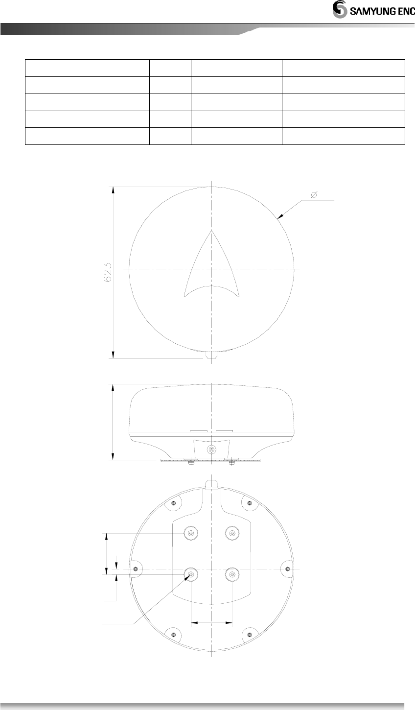
1.4 Construction
150
4-M 10
150
20
600
274
[Pic. 1.1] RSU-3700 External Diagram
6
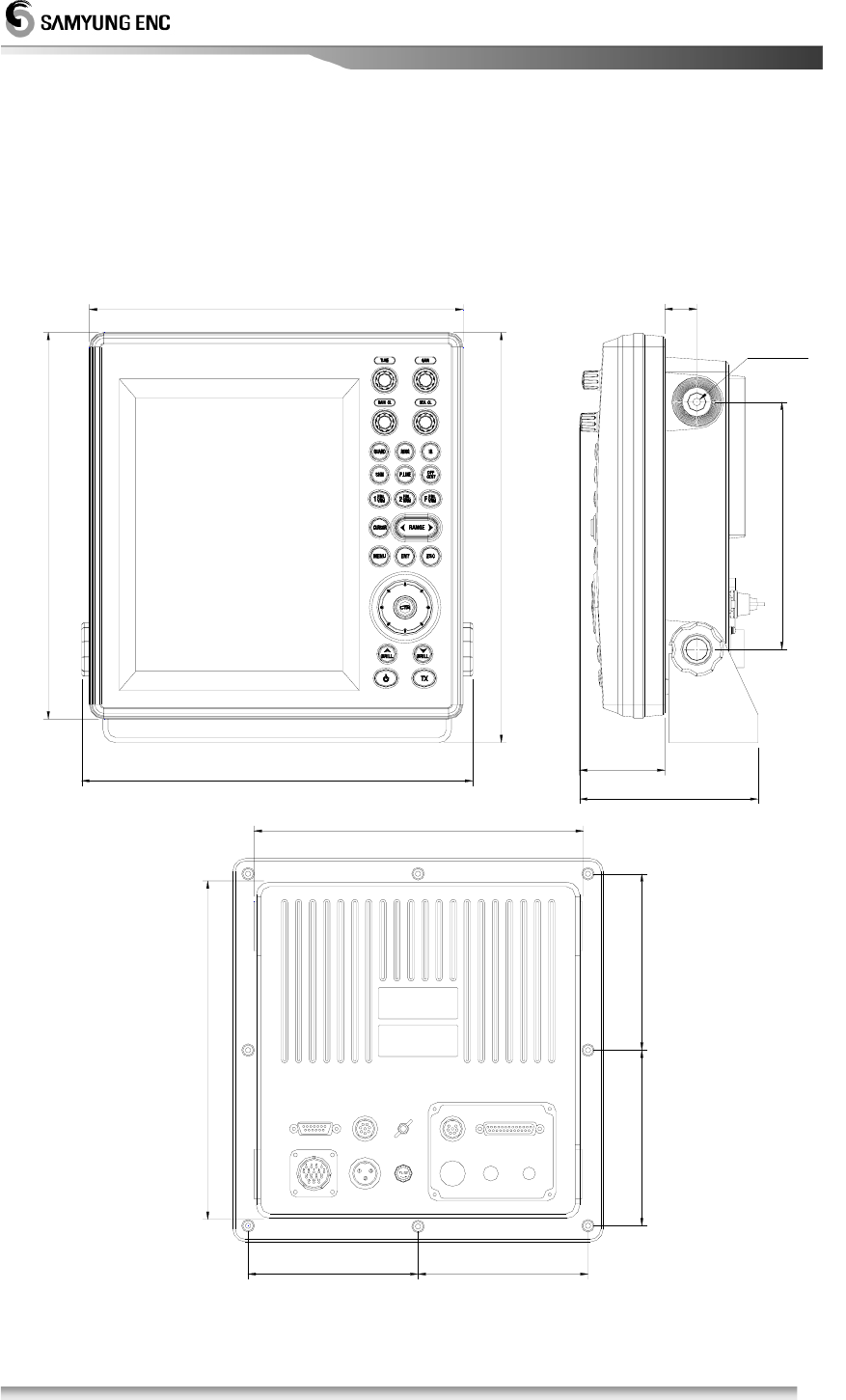
140
138 138
SCANNER
265
133 133
258
POW ER
DOW NLOAD
NMEA
FUSE(7A)
EARTH AIS
EXTENSIO N
67
322
303
307
293 25
4-M 6
194
[Pic.1.2] SMR-3700 External diagram of Display

7
1.5 Specification
1.5.1. General
• Display Type : RASTER SCAN type
• Display Screen : 10.4” Color TFT LCD, Vertical Display
• Display Color : GREEN, YELLOW, RED,WHITE, COLOUR
• Display Range : 0.0625, 0.125, 0.25, 0.5, 0.75, 1, 1.5, 2, 3, 6,
12, 24, 36NM
• Distance Resolution : within 30m
• Min. Detection Range : within 25m
• Bearing Accuracy : ±1°
• Bearing Resolution : 4.2°
• Bearing Input : True Bearing / Magnetic Bearing
• Environmental Condition
1) Temperature : Scanner -25℃ ~ +55℃
: Display -15℃ ~ +55℃
2) Relative Humidity : Scanner - below 95% on 35℃
: Display - below 95% on 35℃
3) Relative Wind Speed : 51.5m/sec (100knots)
• Power Consumption : 78W
• DC Power : DC12V / DC 24V
• Preheating Time : 90 Sec.
• Preaction : within 3 Sec.
1.5.2. Scanner(RSU-3700)
• Dimensions
1) Diameter : 600mm
2) Height : 274mm
• Weight : 9.0Kg (without cable)
• Plane of Polarization : Horizonal Target Wave
• Polar Pattern
1) Horizontal Beam Width : 4.0°
2) Vertical Beam Width : 25°
3) Side Lobe Level : Below -21dB
• Revolution : Approx. 24 R/Min
• TX Frequency : 9410±30MHZ
• Emission Type : P0N

8
• Peal Power : 4KW
• Transmission Bulb : Magnetron JRC MAF1421BY
• Pulse Width Setup
1) 0.1 µsec / 2100Hz - 0.0625, 0.125, 0.25, 0.5, 0.75, 1NM
2) 0.3 µsec / 1650Hz – 1.5, 2, 3NM
3) 0.5 µsec / 1200Hz - 6NM
4) 0.9 µsec / 600Hz - 12, 24, 36NM
1.5.3. Display Unit (SMR-3700)
• Dimensions
1) Width : 307mm
2) Height : 332mm
3) Depth : 140mm
• Construction : Desk Type
• Weight : 4.7kg
• Display Screen : 10.4” Color TFT LCD
• Scale Zoom-In : Less than the bigger one - 1% of used range or 70m
• VRM : .000 ~ 36.0 NM Digital Display
• EBL : .000° ~ 359° Digital Display
• Sync. Type : Manual/Automatic Switchable
• Bearing Scale : 1° scale, 360°
• Bearing Display : Electronic Type
• Front Panel
1) Tune : Knob
2) Gain : Knob / Switch
3) Rain/Snow Removal : Knob / Switch
4)
Sea Cluter Removal : Knob
/
Switch
5)
Guard : Switch
6)
Distance Circle : Switch
7)
Interference Rejection : Switch
8)
Heading Line : Switch
9)
Parallel Line : Switch
10)
Center Movement : Switch
11)
1 EBL/VRM : Switch

9
12) 2 EBL/VRM :
Switch
13) F EBL/VRM :
Switch
14) TEAIL
:
Switch
15) Distance Circle : Switch
16) Menu : Switch
17) Cursor : Switch
18) ESC : Switch
19) Enter : Switch
20) Direction Button : Switch
21) Brightness
: Switch
23) Power : Switch
24) Transmission : Switch
• Menu Type
: POP-UP Type
1.5.4. Connection Cable
• SCANNER Cable Length : Standard 15m / Max 30m
• Power Cable Length : 3m
10
Chapter 2. How to operate panel and menu
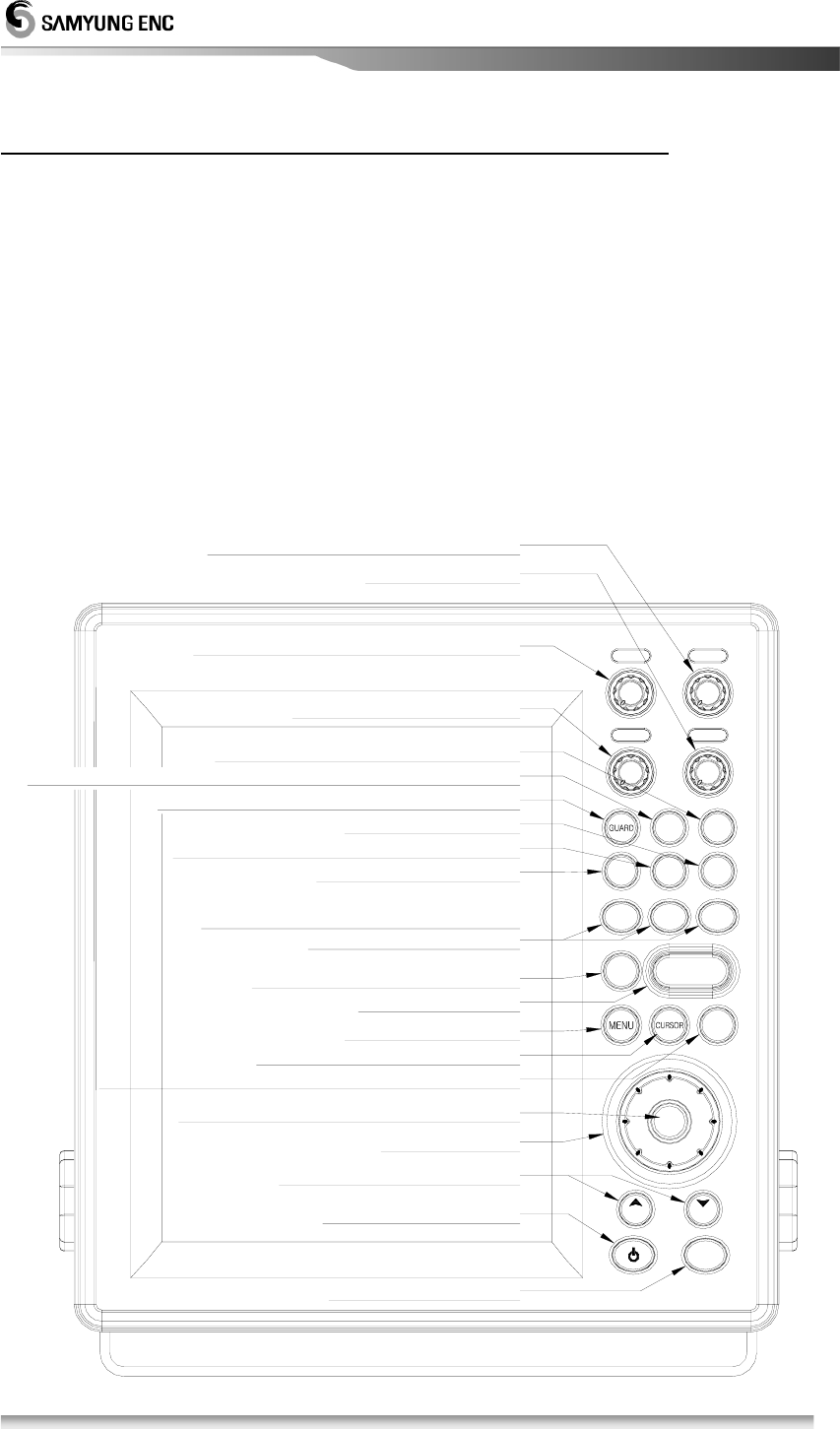
2.1 Front Panel Buttons and Knob
It is available to display and adjust the various data on the screen by using the
the control keys as follows.
• Dedicated 4 (Four) Volumes
• Directional key for 8 (Eight) directions and center key for moving to the display center
• Dedicated 20 (Twenty) keys
• Available to select every function in Menu
2.1.1 Front & Knob Function
Stand by and TX conversion
EBL
VRM
TRAIL
RAIN CL
TU N E
BRILL
SHM
To set up and indicate No. 1 & 2 EBL and VRM
To decide the set value or select the menu item
To return or escape to the previous screen or menu display
To indicate the cursor on the screen
To control the target memory function
To indicate the heading line & the parallel line
To set up the monitor zone and alarm of the screen
To indicate the circle for the reference of the distance measurement
To remove any interference to other radars
To adjust the guard frequency of the receiver
also the flexible EBL and VRM
To turn On / Off the device
To control LCD display brightness
Directional buttons
To call the Menu display
To adjust the distance
To indicate the heading line
To move the image center
To adjust snow and rain clutter
1
To adjust the guard of the receiving signal
To adjust sea clutter
BRILL
ENT
TX
- RANG E +
ESC
OFF
CENT
IR
F
EBL
VRM
2
P.LINE
RING
EBL
VRM
SEA C L
GAIN
11
[Picture 2-1] Front Knob & othe Fron Button
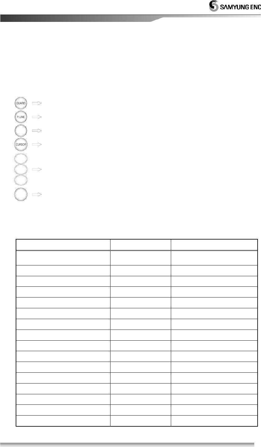
2.1.2 Directional Key
Tey are used to move the cursor, turn the EBL, change the VRM size and move
to any of the sub-menu. They are used to operate the following functions.
To set up the center movement point
To set up the distance & bearing between parallel lines
To set up the alarm zone
To move to the sub-menu
To set up EBL/VRM
MENU
2
VRM
EBL
F
VRM
EBL
To move the cursor
CENT
OFF
1
EBL
VRM
Following is how to operate the exclusive keys.
2.1.3 Display Description
Description Position Display Characters
ALARM Right, Top
ALM1, ALM2
Interferance
Right, Top IR0, IR1, IR2
Sector Blank Right, Top BLANK
Auto Tunning Right, Top TUNE AUTO
Manual Tunning Right, Top TUNE MAN
Target Zoom-In Left, Top EXT1, EXT2
Waypoint Memory Left, Top W1, W2, W3, W4
Heading Display Mode Left, Top H-UP, N-UP, C-UP
Screen Zoom-In Left, Top ZOOM
Heading Bearing
Middle, Top HDG
Gain Middle, Bottom GAIN
Rain & Snow Clearing Middle, Bottom RAIN CL
Sea Clutter Clearing Middle, Bottom SEA CL
Auto Gain Right, Bottom GAIN-A
Auto Rain & Snow Clearing Right, Bottom RAIN-A
Auto Sea Clutter Clearing Right, Bottom SEA-A
12
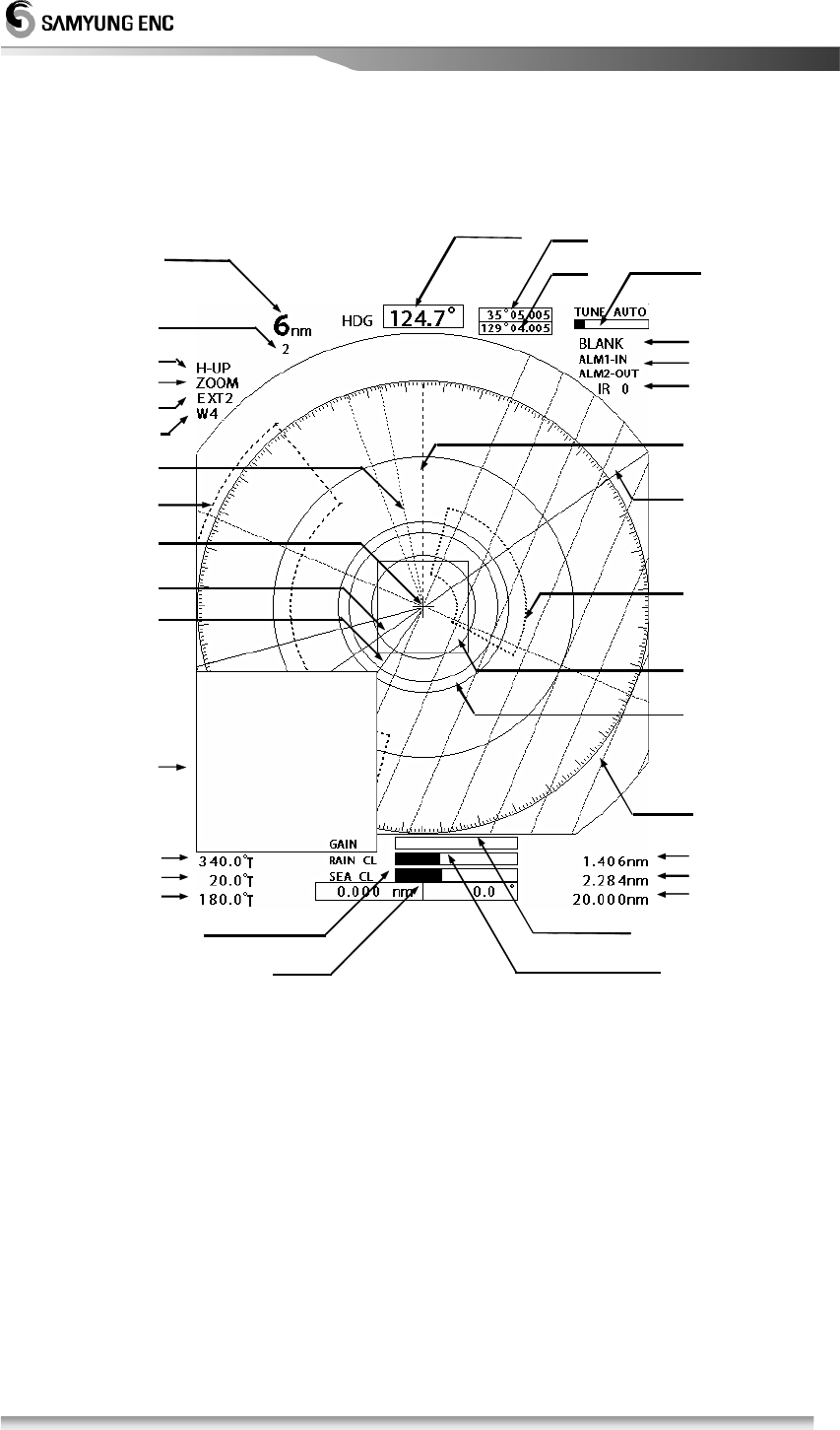
2.2 Display Description
Lo n gitude
Latitude
A u to T u n in g
Blank
Sector
Alarm Set
In te rfe re n c e
C learing
H eading Bearing
R ange
Cursor
Zoom -In Display Sector
H eading Display
Target Zoom -In
Waypoint m em ory
1 EBL
Zoom -In Display
2 EBL
F EBL
1 VR M
2 VR M
F VRM
Gain control d isplay
S now & Rain clearing control d isplay
Sea clutter control d isplay
C u rs o r P o s itio n
Parallel L ine
F EBL
G uard Zone 1
1 VRM
2 VRM
Alarm 2 Zone
2 EBL
1 EBL
H eading Line
Blank SectorZone
D istance betw een range ring
• The bearing, speed, latitude, longitude on the top of the screen and the destination
setup on the right bottom of the screen are displayed only when the signal from Gyro
and GPS is input data port.
13
2.3 Menu Functions
In addition to the functions used by the front panel keys, SMR-3700 has the
functions to enable user to control with menu.
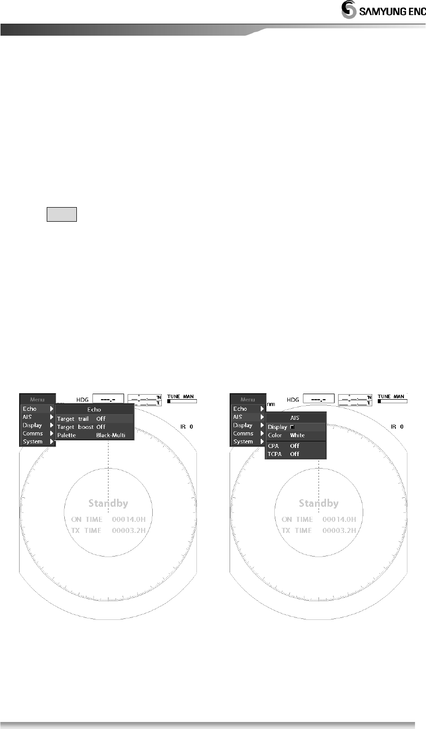
2.3.1 Menu Composition
It is available to converse the display language to Korean, English and other
languages.
Press MENU and select any wishful setup menu by using direction button.
There are total of five (5) different menus and each menu function explained
as following;
◎ Echo Menu : Menu setting for the target display
◎ AIS Menu : Menu setting for the AIS display
◎ Display Menu : Menu setting for the display colors and other functions.
◎ Comms (Communication) Menu : Menu setting for external devices and c
ommunication speed or usage.
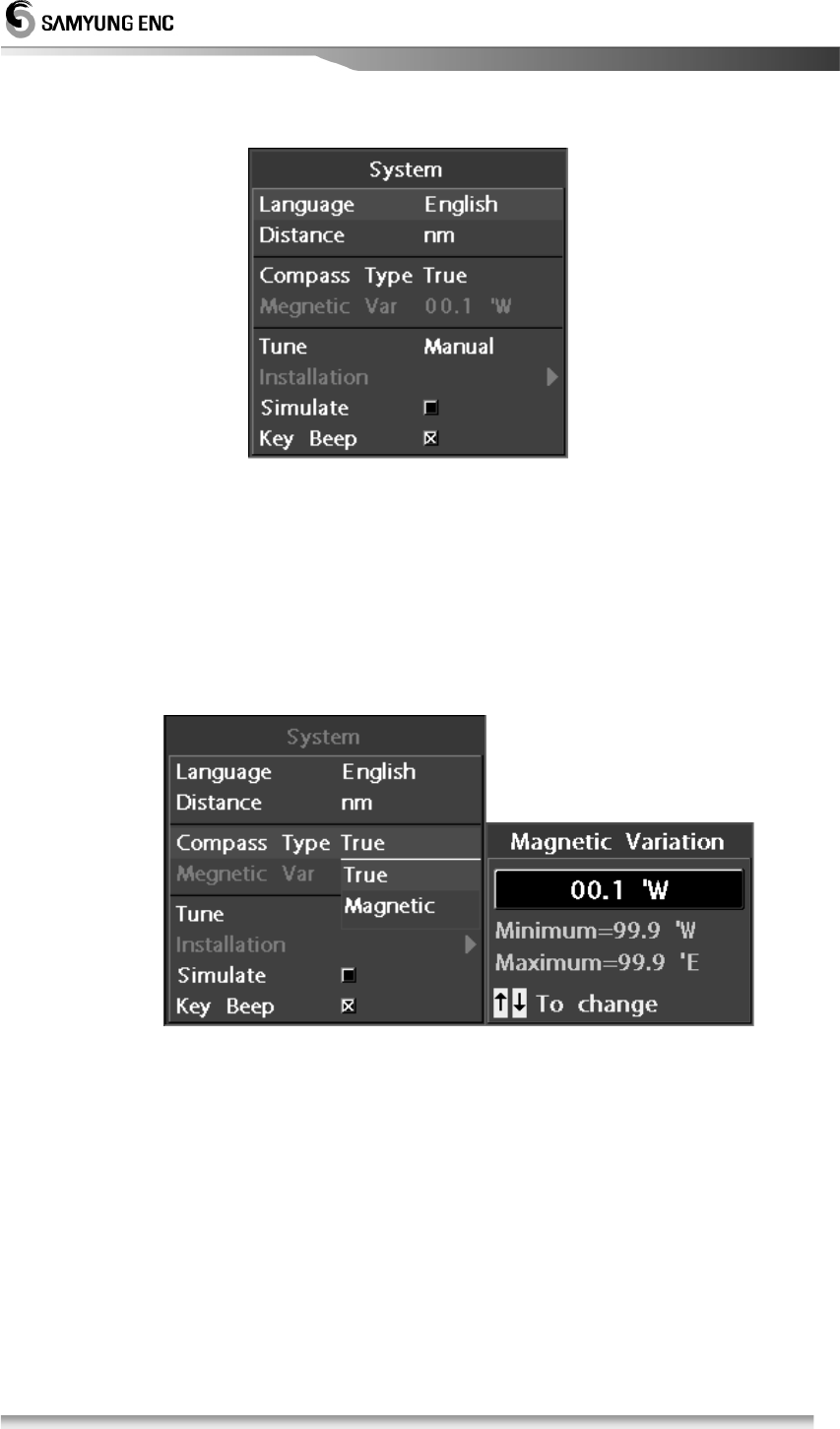
◎ System Menu : Sets languages and equipment’s initial setting menu
[Echo Menu] [AIS Menu]
14
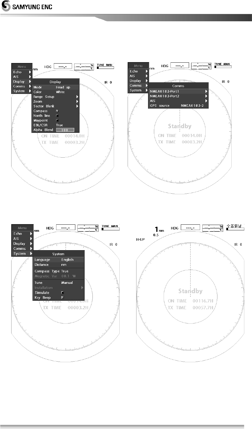
[Display Menu] [Communication Menu]
[System Menu] [Initial Display]
15
2.3.2 Menu fucntions
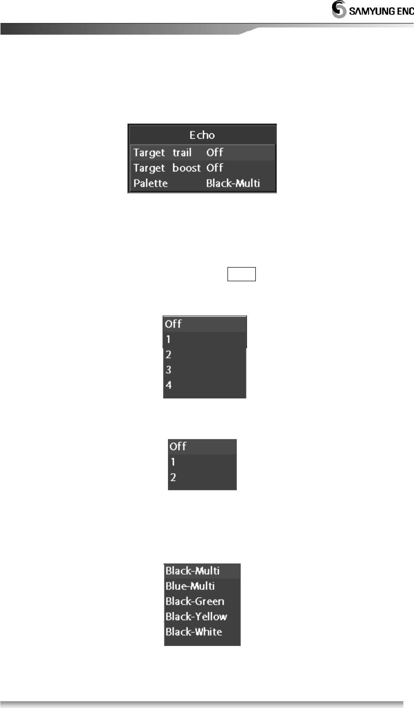
2.3.2.1 Echo Settings
• Target trail
Traget trail can be display by setting of the revolution number, and it can
be display target’s moving status with different colors.
This function will operate by press TRAIL. Revoluation can be adjusted
from Off status then 1
st
to 4
th
revoulouation. Current setting status will be
disply on the left upper screen cornor.
• Target boost
Set and adjust the target boost size with two (2) different levels.
• Palette Color Selection
User can select a favorite color from one of five (5) different colors of the
target.
Example) Black-Multi: Black background color with any color of target.
16
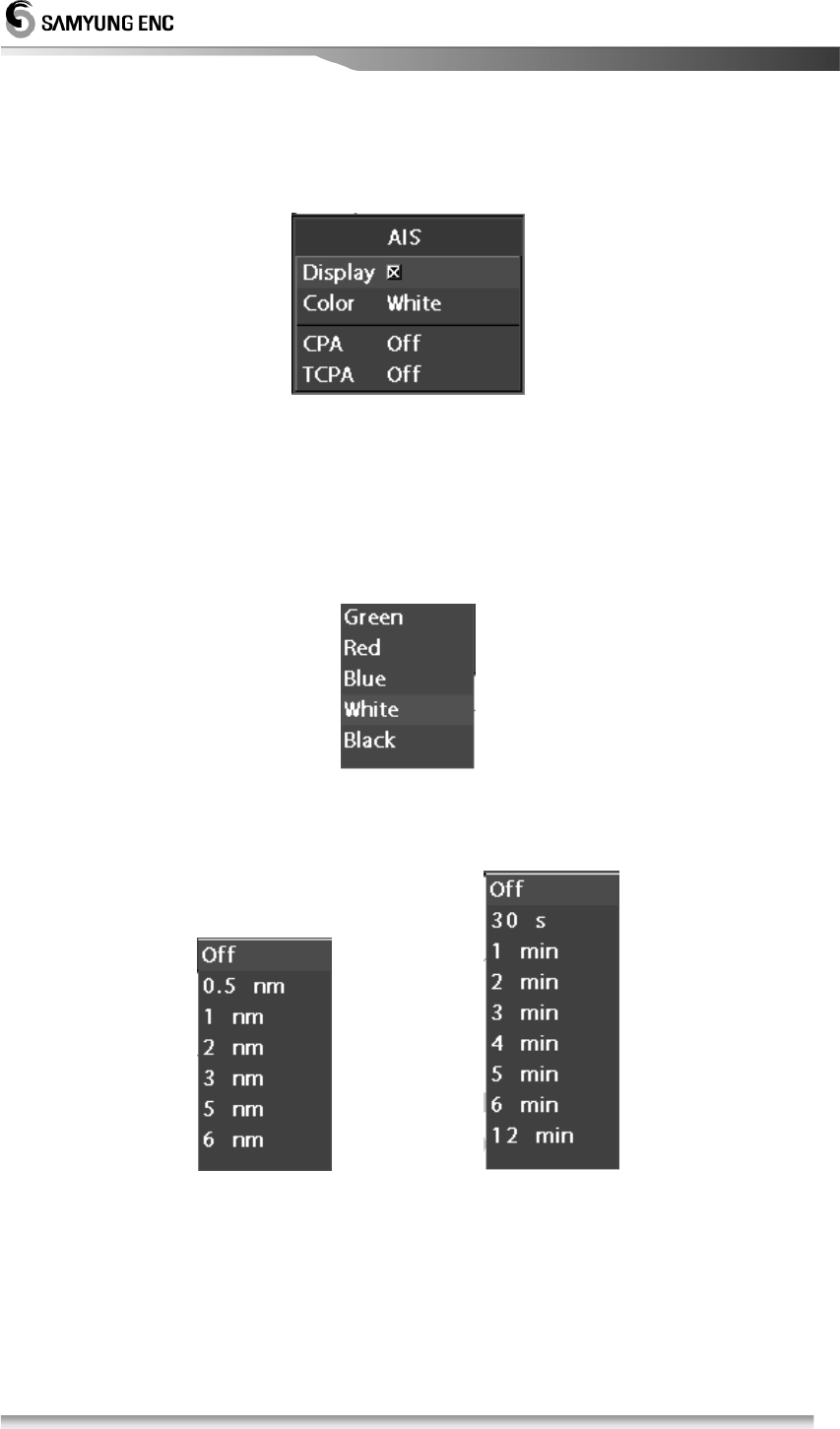
2.3.2.2 AIS Setting
• Display
Select either display of AIS or not.
• Colors
Selecting a color of AIS target; you can choose Green, Red, Blue, White,
or Black.
• CPA, TCPA (AIS Alarm Setting)
Setting menu for the AIS’ target wreck alarm of CPA distance set,
TCPA is setting for approximate time of wrecking.
(CPA Menu) (TCPA Menu)
17
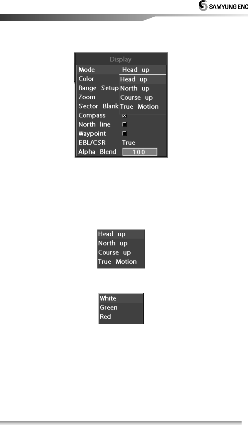
2.3.2.3 Display setting
• Mode
This menu is available to display bow, N-UP, C-UP and True Motion.
It’s only available to display Bow mode when there is no external
signal,
It is available to select N-UP, C-Up and True Motion mode when
thereis an external signal of bow
※ Course means the waypoint set externaly
• Colour
It’s available to select the colours between white, green, red for letters.
• Distance setting
You can set the distance unit from 0.0625, 0.125, 0.25, 0.5, 0.75, 1,
1.5, 2, 3, 6, 12, 24 to 36 but when 0.0625 is not available to use with
km(kilometers) - mode.
18
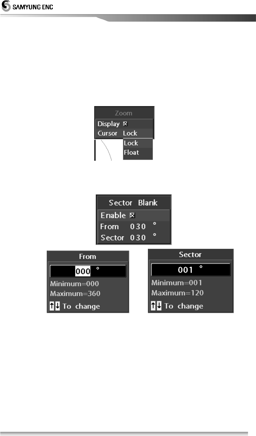
• Zoom
This function is to zoom up and it’s available to zoom up x 2 and
display the left or right conner in the bottom of the display
There are two display functions, Cursor Lock and Cursor Float
Cursor Lock : Move cursor where you want to see and zoom up
aroundthe cursor.
Cursor Float : Zoom up the the cursor is.
• Sector Blank
You can set Sector Blank in the radius 360˚ by 1 degree..
It will be displayed with blue broken lines.
• Compass
You can turn on/off the compass function in the screen.
• North line
You can turn on/ff the North line in the screen.
• Way point
You can turn on/off the way points from other equipment.
• EBL/CSR
You can select EBL/CSR to be Relative or True.
• Alpha Blend
You can set transparency of POP-UP menu between 50 to 100.
19
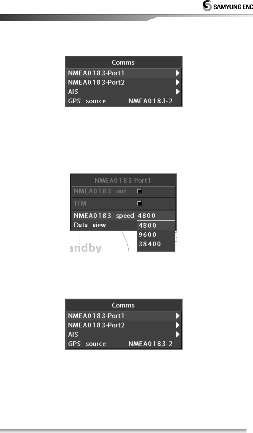
2.3.2.4 Communication setting
• NMEA0183-Port
This is a menu to set NMEA0183 port, you can check the transmission
speed and communication status. It provides Communication speed at
4800, 9600 and 38400.
You can check the communication status of receiving signal from
other equipment.
• AIS
A function to check the communicate condition to other equipment.
• GPS Input
A function to select GPS input port.
20
2.3.2.4 System setting
• Language setting
Select a language what you use.
• Distance measure
You can choose among nm, mi, km
• Compass Type
You can select radar image with true heading or self heading.
Self adjustment is to adjust information of self heading.
• Tuning
You can set Auto/Manual a way of setting TX and RX.
• Installation Setting
A function to set a equipment, please refer 5.6 article.
※ It’s not operated in the beginning, please refer 5.6.1 Initial setting
menu to use this function.
• Simulation
A function to check operation without scanner.
• Key beep
You can turn on/off button beep.
21
Chapter 3. How to operate the unit
3.1 General Idea
3.1.1 Power input and Operation
1. Power input
• To power on, press POWER button.
• Afte power on, Count Down Timer is displayed on SAMYUNG Logo screen,
it is converted to the stand-by in 1 min. 30 secs.
• As the TX time is consolidated and displayed, user can judge the ideal time
for repair..
• It indicates the version of the program..
[Refer] When it is not available to power off due to programme is down,
please push OFF switch for 10 seconds so that you can turn it off by force.
2. TX
•
Press button to enable the transmission at the stand-by status.
.
• Press button again to convert the TX status to the stand-by status.
3.1.2 Tuning control
It is required to control the tuning of the unit both manually and automatically.
The conversion is selectable in the setup of MENU.
For the automatica tuning,“Auto Tuning” is displayed next to the tuning bar.
1. Change tuning mode
• Menu Æ System Æ Tuning Æ Auto / Manual Æ Input Æ Return
2. Control tuning volume
• In case of tha manual tuning mode, turn the volume to adjust the image
biggest.
• Adjust the movement of the tuning bar biggest..
• In case of the automatic tuning mode, it is needless to turn the volume.
• If any image doesn’t appear, adjust the volume again or turn the volume of
/ (rain/snow) removal.
3.1.3 Image control
the volume of the tuning/gain of (sea clutter),
(rain/snow), removal to display the optimum image.
22
3.1.4 Power off
1. Stop transmission(TX).
• Push T X key to be ready to transmit .
2. Turn off the Power.
• Push POWER key for 3 seconds then power will be turned off.
ex) The parts for power on are operating while power is offed so please
disconnect power completely if you don’t use this equipment for long.
3.2 Stand by for processing
3.2.1 Brightness change
• Press brightness key.
Push ▲ key to brighten the screen, push ▼ key to darken the screen.
There are 10 levels you can adjust.
3.2.2 Language Selection
• Menu Æ Æ System Æ Languange Æ Select user’s language Æ Input Æ Return
Select language what user wants to use.
3.3 Basic Operation
3.3.1 TX
• Press T X button, it will be converted to TX from the stand-by status.
3.3.2 TX Stop
• Press T X button again at the TX, it will be the stand-by status.
3.3.3 Tuning Control
• Please refer to [3.1.2 Tuning Control].
23
3.3.4 Gain control
• Turn gain key.
When you turn to left, decreasing the gain, when you turn to right,
Increasing the gain.
• To adjust the optimum gain
It’s the maximum size of ECHO image by object, by object very closed, It’s
not contacted to ECHO image.
.감도가 낮아 영상이 작다 .감도가 최적이다 2감도가 높아 개의
.영상이 붙었다
• Auto gain setting
When you push the switch in the gain volume, it will be displayed AUTO in
the centre of bottom of the screen, it will be displayed GAIN-A in the right
corner of the bottom of the screen.
This function is set the optimum environment without adjusting gain but there
isa possibility to be some noise up to the environment.
ATTENTION
※ It should be always observed by adjusting the optimum conditions.
※ If the gain is too low, the targets may not be displayed.
※ If too high, it may be an obstade in observation due to the noise increase on the display.
Small image by low gain Optimum gain 2 Images contact by
high gain
24
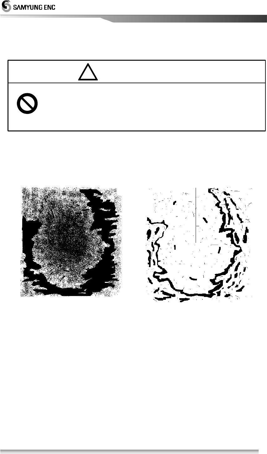
3.3.5 In order to remove the interference of rain/snow
!
• If much rain/snow, it is difficult to analyze the wishful target image as the echo
by rain/snow clutter appears on the display.
• Turn Rain CL to the right to remove the echo image by snow and rain.
Reflected wave of rain/snow Removed rain/snow
(Target is restricted, too.)
• Auto setting rain/snow
When you push the switch in the volume for removal rain/snow, it will be
displayed AUTO in Rain CL in the middle of bottom of screen, it’ll be displayed
RAIN-A in the right conner of bottom of screen.
This function is to make a best display setting without managing the removal
snow/rain volume but please don’t use this function when it doesn’t need to
manage removal rain/snow because this fuction makes target smaller than
usual.
※ Too much adjustment of rain/snow removal will restrain the target of shipsor
hazards as well as any images by rain/snow. This can be the cause of image
analysis.
※ In case of use of rain/snow removal, the optimum conditions shoud alwaysset
up
ATTENTION
25
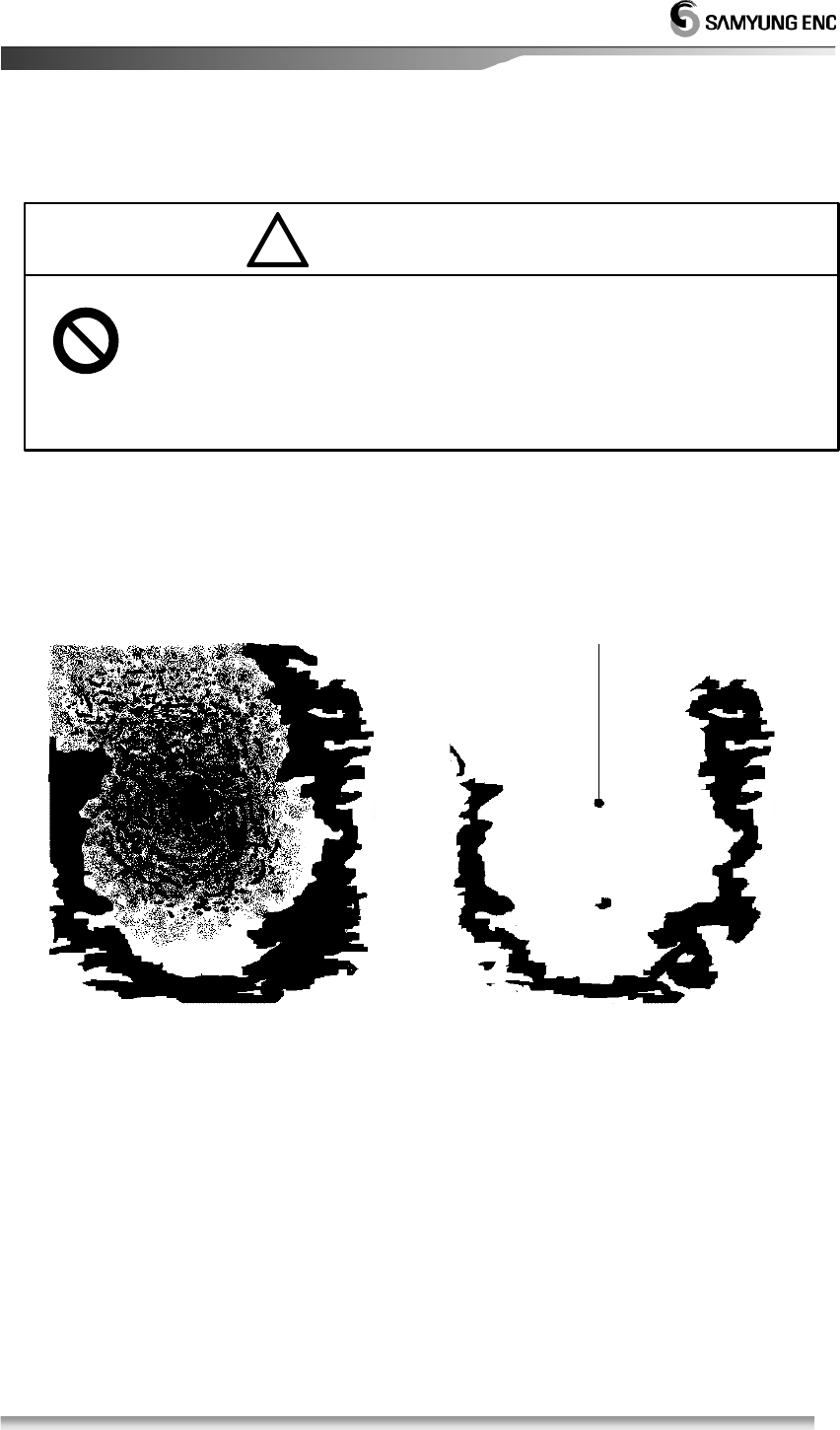
3.3.6 To remove the interference of Sea Level Wave caused by the Sea Wave
!
• When the wave becomes high due to heavy wind, the ECHO(Sea clutter)
due to the wave is displayed on the screen, then it will be difficult to detect
the image of the target.
• Turn Sea Clutter key to the right to remove the echo image by wave.
The status that shows Sea Level Reflection The status that shows Sea Level Reflection
is strong due to Wave. is being suppressed.
(The target is also suppressed)
• Auto Sea Clutter removal setting
When you switch on Sea Clutter remove, it will be displayed AUTO in the
Centre of bottom of screen, it will displayed SEA-A in the right corner of
bottom of the screen.
This function is automatically set the optimum function for display.
But it is not necessary to set this function when you don’t need to remove
Sea Clutter because the target will be small.
ATTENTION
※ If you set the removal function of Sea Level Wave up to removal of all Sea Level
Reflection at short distance, it causes intereference in detecting images due to the
target of vessel and dangerous things as well as the wave images being suppressed.
※ When you use the removal function of Sea Level Wave, you make sure it should be the
optimistic set of suppreession
26
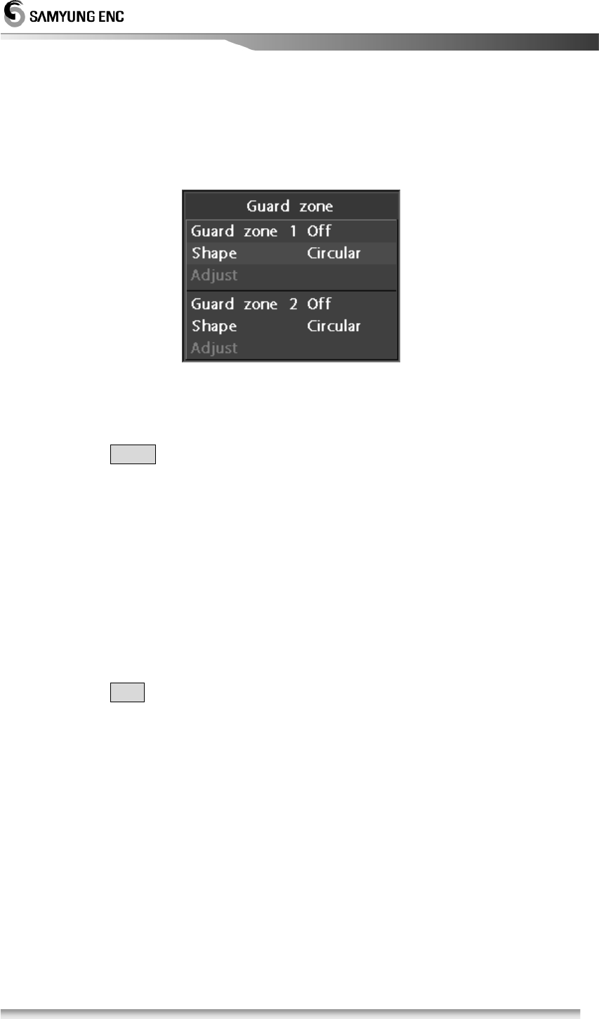
3.3.7 To operate the alert function
•
Set
the guide zone in order to use the alert.
• Guard Zone means [Zone] to be set on PPI screen
1. Guard Zone Setting
• Locate the cursor where you want to move
• Press the Alert key
• POP-UP Menu will be appeared to set up two different guide zones on the
screen
• Select incursion or separation of guide zone.
• Incursion means the target enters into the zone and sepatation means the
target come out of the zone. In each case, the alert sound will come outt
• Select Ring or Fan
Ring function will create ring-shaped guide zone and Fan function will create
Fan-shaped guide zone.
• Press Adjust and then move the cursor to set up the guide zone.
• Press the input key.
• After a desired guide zone is done then exit
2. Occurrence and Stoppage of the alert sound
• After setting up the guide zone, the alert sound will come out once the target
enther into the zone.
• To stop the alert sound, press any key on the device.
3. Termination of the alert
• To terminate the alert status, press the alert key and then select the alert zone
off.
27
3.3.8 To eliminate/display the scale of Range Ring
1. Press the Range Ring Key
• The brightness of ON/OFF will be adjusted.
3.3.9 To eliminate the radar interference
Radar Interferene means Micowave transmited by other ship’s Radar is displayed
on PPI screen, which is directly affecting to own ship’s Radar air line.
1. Press the interference removal key
• Whenever pressing button,
it marks with IR-1, IR-2, IR-3 in order in the
top-right screen.
IR- 1
Before Interference Removal After Interference Removal
※ When using the function of Intereference Removal, weak image such as a
dangerous thing may happen to be removed.
※ Stop the function of interference removal when you see Radar BEACON an
SART signal.
Caution
Radar interference
Interference
Removal
Function
28
3.3.10 To change the color of the ship’s heading line.
1. Press the ship’s heading line key
• Ship’s heading line is indicating own ship’s heading direction.
• When the key is pressed, the brightness will be adjusted in 3 different
degrees.
3.3.11 To use the parallel line
1. Press the parallel line key
2. To adjust the distance and the bearing, use the diagonal key as follows;
• key can adjust the bearing of the parallel line.
• key can adjust the distance of the parallel line.
3.3.12 To move the center of own ship
It can use for securing the wider sight to the specific direction from the center of own
ship.
1. Move the curor to a desirable position.
2. The center of own ship moves to the position of the cursor by pressing centrer
movement.
• It can be moved up to 60 percent of the screen.
3. Once center movement key is pressed, it will turn back to the original position.
3.3.13 To measure the distance and bearing to the target.
Method 1. By using EBL/VRM, the distance and bearing of target can be
measured.
EBL means Electronic Bearing Line.
VRM means Variable Range Maker.
Method 2. By using cursor, the distance and bearing of the target can be
measured.
1. Measurement of the distance and bearing by using 1 EBL/VRM
• Press the 1 EBL/VRM key.
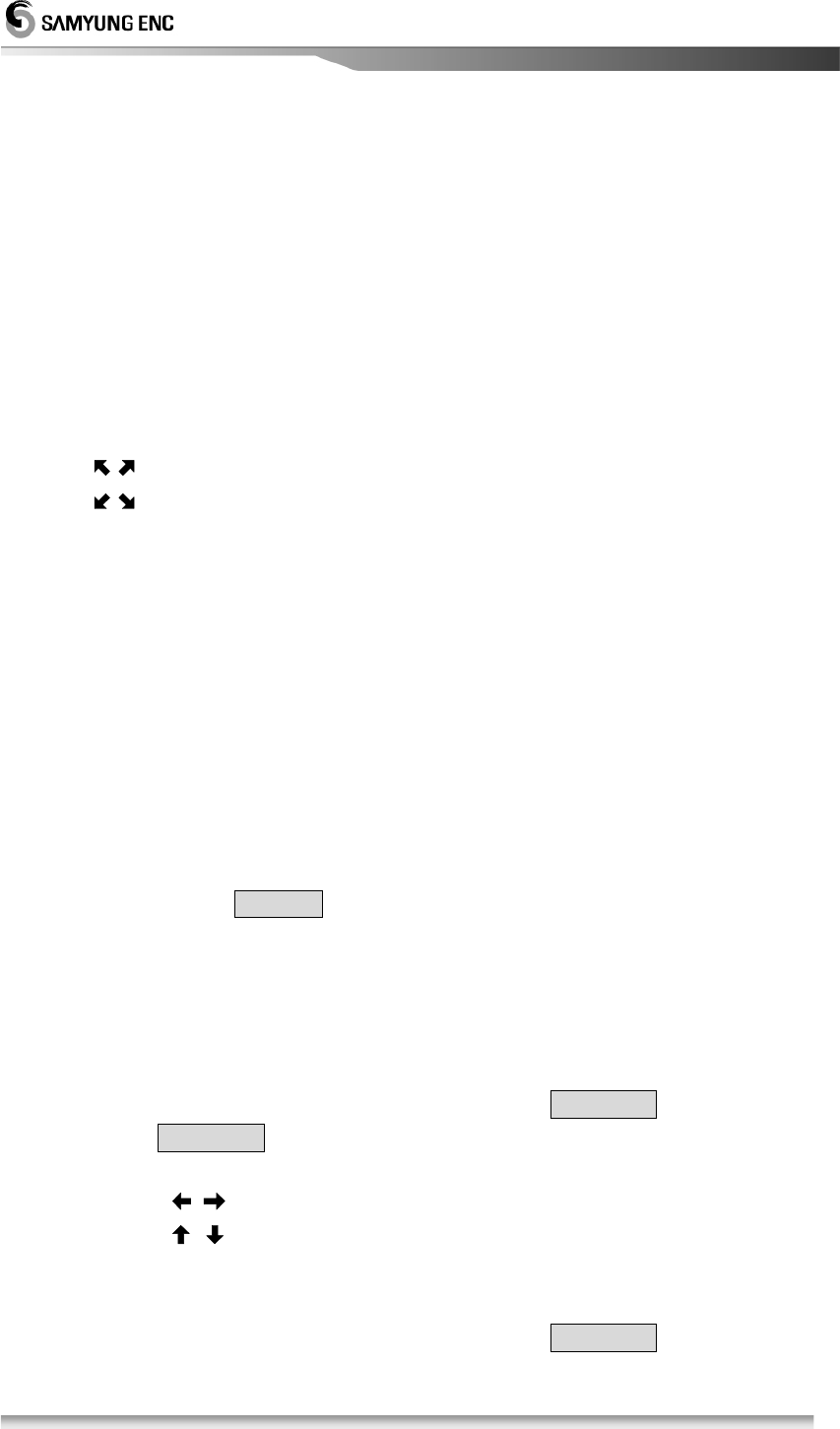
•
VRM & EBL are shown at the center of the screen
• By pressing , it can move the EBL.
• By pressing , it can move the VRM.
• Distance/Bearing value appears on the bottom of the screen.
• To exit, press ESC key.
2. Measurement of the distance and bearing by using 2 EBL/VRM
• The method will be same as 1 EBL/VRM.
29
3. Measurement of the distance and bearing by using F EBL/VRM
• Press the F EBL/VRM key.
• EBL/VRM will appear on the radar screen.
• Once the cursor is appeared, move to the desired position.
• By pressing Center Movement key, the center of F EBL/VRM will be shifted and
will be back to the original position by repressing the key.
• By pressing cursor, cursor will be disappeared and then use the direction key
to move EBL/VRM to the desired position.
• The value of distance and bearing will appear on the bottom end of the
screen..
• To exit, press the esc key.
[Ref] F EBL/VRM can be used to indicate EBL/VRM on the specified position.
4. Measurement of the distance and bearing by using Cursor
• By using Cursor, cross shaped cursor will be appeared on the radar screen.
• The value of distance and bearing will appear at the bottom end of the
screen,where the cursor is located.
3.3.14 To change the distance uni
1. NM (Nautical Mile)
Menu Æ System Æ Distance unit Æ Input Æ NM Æ Input Æ Esc
• Cursor, VRM, Distance of parallel line represents NM.
2. Mile
Menu Æ Sytem Æ Distance unit Æ Input Æ Mi Æ Input Æ Esc
• Cursor, VRM, Distance of parallel line represents Mi
3. Kilometer (Km)
Menu Æ System Æ Distance unit Æ Input Æ KM Æ Input Æ Esc
• Cursor, VRM, Distance of parallel line represents KM.
30
3.3.15 To change the way of direction symbol
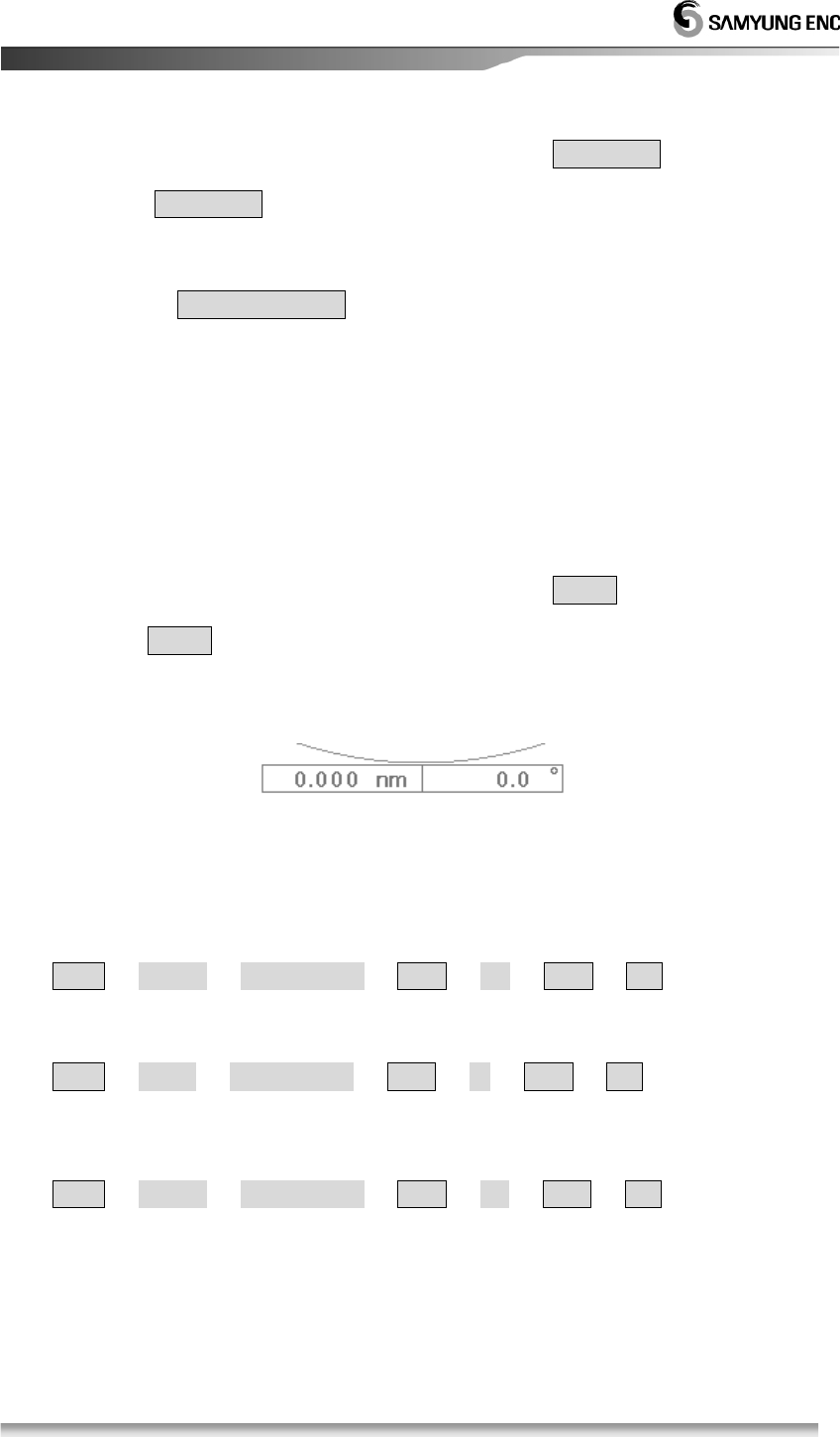
1. Indication of ship’s head line (H-UP)
Menu Æ Indication Æ Mode Æ Input Æ Head Æ Input Æ Esc
• Ship’s head is displayed to the HEAD UP.
• If ship’s head is changed, ECHO image bearing on the screen is also
changed.
• If you could not obtain bearing reference from external navigation
equipment like Gyro Compass, it sets out with this bearing display.
Image moves to the left.
When the own ship turn right to
45 degree
31
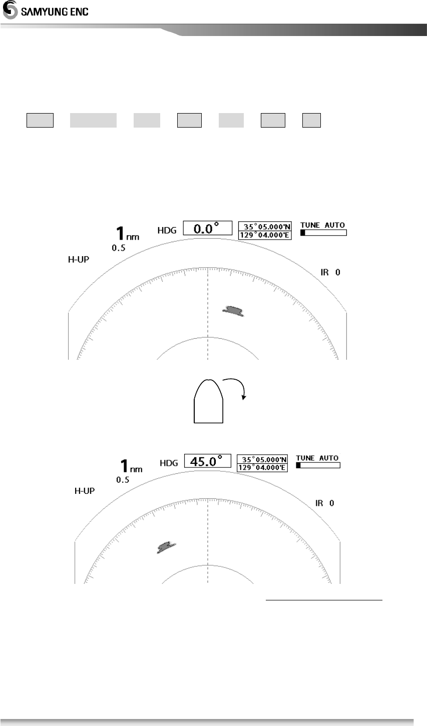
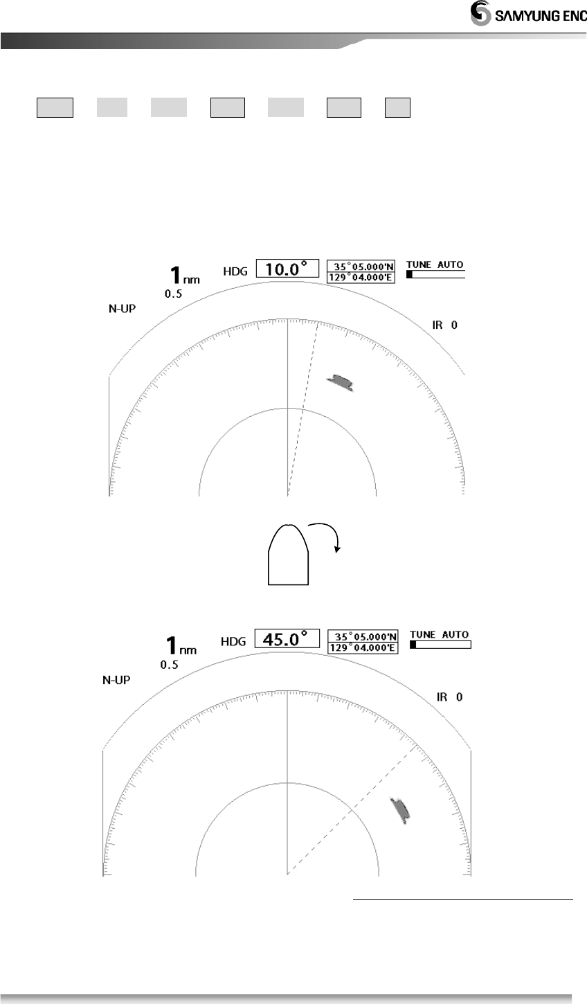
2. Indication of North direction
Menu Æ View Æ Mode Æ Input Æ North Æ Input Æ Esc
• The vertical line will indicate the direction of the North, the line to 10 degree
indicates the ship’s heading line.
• The angle of bearing will be changed based on the North direction on the
screen.
• It requires the equipment like GYRO COMPASS to obtain bearing information.
Ship’s headling moves to the right.
When the own ship turn right to
35 degree.
32
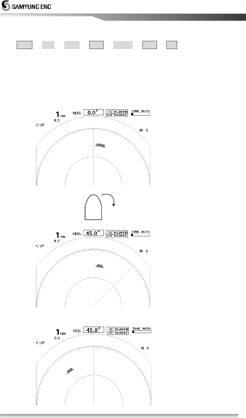
3. Indication of course-up (C-UP)
Menu Æ View Æ Mode Æ Input Æ Course Æ Input Æ Esc
• Make the ship’s head line on the screen when the course-up is excuted.
• Even though ship’s head direction is changed, Echo image bearing moves as
much as the variation of ship’s heading bearing.
• When you change the track widely, set the course up again from the MENU.
• It requires the equipment like GYRO COMPASS to obtain bearing information.
Head Line moves to the right.
When the course up is reset
When the own ship turn right
to 45 degree
33
3.3.16 To change the way of bearing display
1. True Bearing
Menu Æ System Æ Bearing Display Æ Input Æ True Bearing Æ Input Æ Esc
• True bearing indication is set based on true north with scale 0.
• It requires the equipment like GYRO COMPASS.
2. Magnetic Bearing
Menu Æ System Æ Bearing Display Æ Input Æ Magnetic Bearing Æ Input Æ Esc
• Magnetic Bearing indication is set based on Magnetic North with Scale 0.
• MAGNET COMPASS is needed.
3.3.17 To change the way of displaying bearing line/cursor.
When you display the value of EBL bearing, select between the own ship and
True North as a base.
1. ‘Relative’ Indication
Menu Æ View Æ EBL/Cursor Æ Input Æ Relative Æ Input Æ Esc
• Make the cursor, and the bearing value of EBL indicate based on ship’s
heading line (Ship’s head line is 0)
4. True North Indication
Menu Æ View Æ EBL/Cursor Æ Input Æ True North Æ Input Æ Esc
• Make the cursor, the bearing value of EBL indicate based on True North
(True North is “0”)
3.3.18 To compensate the magnetic
Enter the value of compensation because Magnetic North Bearing is slightly
different according to the navigation zone.
Menu Æ System Æ Magnetic Compensation Æ Input Æ Enter the value by cursor
Æ Input Æ Esc
• Enter the value manually.
• Enter the value using direction key.(99.9 ‘W ~ 99.9 ’E)
• Direction key will shifted by ±0.1 with ↑ ↓ and ± 1.0 with ← →.
34
3.3.19 To display the trace of the target.
• It can ascertain the other ship’s movement in track line distance and
directionand it facilitates to avoid collision of the ship.
• The longer target track line ls displayed, the faster the other ship’s speed is
and vice versa.
• The length of the track line is displayed ranging from 1 to 4 cycles.
1. Activation of the target trace
Menu Æ Echo Æ Target trace Æ Input Æ 1~4 Æ Input Æ Esc or TRAIL
• The revolution of the scanner will be displayed from 1 to 4 cycles.
• The color of the tarket track line will be changed in each cycle.
• On the upper left side of the screen, the status (W1~W4) will be displayed.
2. Deactivation of the target trace
Menu Æ Echo Æ Target Trace Æ Input Æ OFF Æ Input Æ Esc or TRAIL
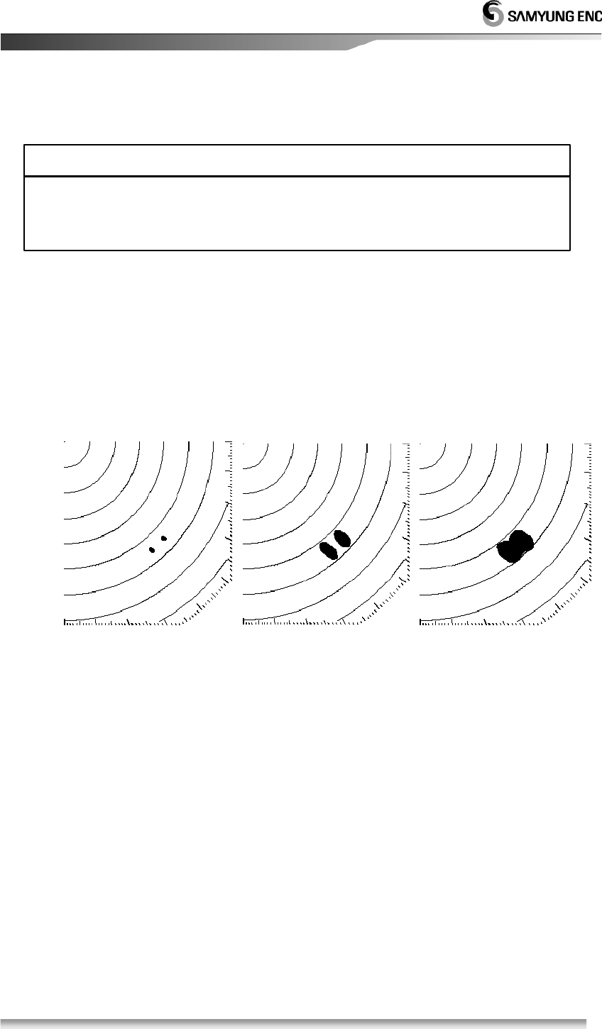
3.3.20 To display ECHO image wider on the radar screen.
To expand the ECHO image, use the following steps
• Use the function of the target expansion.
• Set the width of TX Pulse long.
1. Activation of the target expansion
Menu Æ Echo Æ Target Expansion Æ Input Æ 1~2 Æ Input Æ Esc
• The size of the target on the screen will be doubled.
2. Deactivation of the target expansion
Menu Æ Echo Æ Target Expansion Æ Input Æ OFF Æ Input Æ Esc
• It will turn back to the original status,
※
When designating the target magnification and wider transmit pulse width, the
imagesover two targets accessed from fore and after direction and angle
direction.
Caution
35
3.3.21 To change the color of the radar screen and ECHO image.
1. Configuration of the color of ECHO image and background.
Menu Æ Echo Æ Color Selection Æ Input Æ Choose the color Æ Input Æ Esc
• On the botton left of the screen, coler level will appear.
• During the night navigation, make background color dark and set the LCD
brightness to the low level, it will help relieving eye’s fatigue.
3.4 Connection to the external navigation equipment
• At the rear side of the indicator, connect to the external navigation equipment
through data terminal.
EARTH
FUSE(7A)
SCANNER
2
NMEA
6. NMEA2 TX
8. GND
7. NMEA2 RX CABLE
8
45
6
7
1
3
5. +12V OUT
2. GND
1. SHIELD
3. NMEA1 TX
4. NMEA1 RX
DATA
NMEA
DOW NLOAD
NMEA
5. +12V OUT
2. GND
4. AIS TX-
6. AIS RX+
7. AIS RX-
3. AIS TX+
1. SHIELD
CABLE
AIS
AIS
DATA
4
3
8
2
1
5
6
EXTENSION
AIS
36
Chapter 4. Screen view
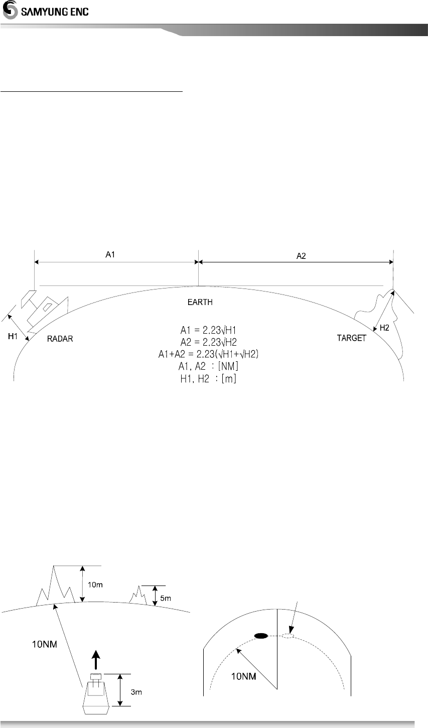
4.1 The distance from the target to the height of target
The longest distance observable to the target is depending on the height of target,
the distance to the target and the height of antenna other than the matter of
performance like Tx power, Antenna beam width and receiving sensitivity. Radar
signal is linear nature that is not affected by a round
earth.
For example, when the height of antenna is 3 meters above sea level, the ECHO
image of island of 10 meters’ height and 10 miles away from the antenna can be
displayed on Screen but the 5 meter’s height with same distance is not displayed on
screen since Radar signal transmitted does not reach.
But, these are of theoretical value and would not be constant due to environmental
condition. In theory, the target 10 miles away from the antenna requires 7.6 meters’
height, if it is lower than 7.6 meter, ECHO image would not appear for which you
must keep in mind.
The island, which is not displayed on Screen
37
4.2 Reflection from the target
• The strength of reflection from the target is related to not only the size of the target
but the shape of the materials composed of it, therefore the strength of reflection is
not considered to be relative to the size of the target.
• Especially it is dependant to the geographical condition in coastal line. If the
coastal line is flat slide, the only mountain summit is displayed on the screen as an
image, you should pay attention to the calculation of distance upto the coastal line.
• The ECHO reflected from flat land is so weak that it is unlikely to observe such
land.
4.3 Wave Path
•
In case there is an obstruction in the course of wave path like Mountain, Rain and Snow,
the target behind of them may not be observed.
우설과 산으로 가려져 물표가
나타나지 않음
4.3.1
Reflection of sea level
• On the sea surface where are made, white and broad images are displayed on the
screen center. This is a reflection created from the sea level and occurs as a
different image mainly depending on the size of save, range and the direction of
wind.
The tar
g
et does not a
pp
ear due to
SNOW and Mountain.
Coastal line
Mountain
Coastal line
Mountain

38
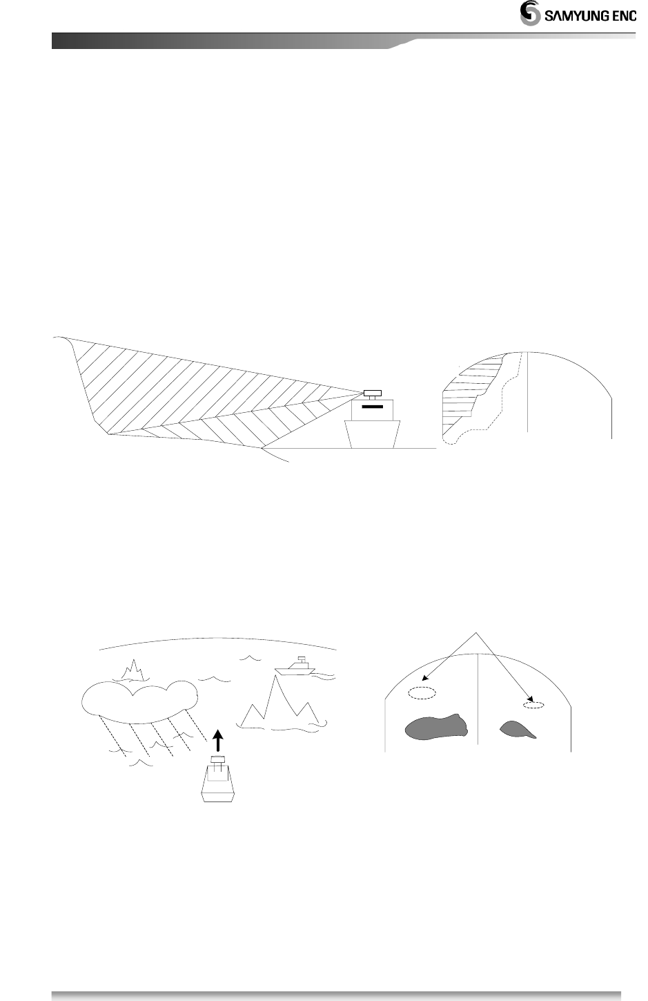
4.3.2 False Image
There is a possibility that non-existing targets may be shown or any existing
targets may not be shown through the image. This image is called ‘virtual image’.
What mainly causes such false image as follows;
1. Shadow
Dipending on the installation position of antenna, the reflection may come back
after colliding against the funnel or mast, which may create ‘shadow’ causing
the virtual image on PPI screen. In this case, the targets that are located at the
shodow direction may not be shown on the screen.
The existence of such a ‘shadow’ can be figured out by checking if there is any
dim image or any unseen part, based on the reflection of sea level.
If the ‘shadow’ occurs, the user needs to memorize the direction in order to
observe the targets with care.
2. Side echo
There may be an image of arc wave line in the same distance from target image
on the screen. This is caused by the side lobe of which beam is radiated from
the antenna.
For this phase, it is easy to make a judgment when targets are fixed.
3. Secondary reflection
Fake images may be displayed as their directions are changed through being
reflected against the funnel or mast, which create shadow.
In this case, the images of targets are located at the mast direction that reflects
the radar wave.
4. Multi-reflection image
Where there are any structures or big-sized vessels that are hidden behind
gigantic vertical line, multiple images by multi-reflection appear.
These images come out at intervals of every lamp line and among the lines, the
closest line to the own ship is the actual image of target.
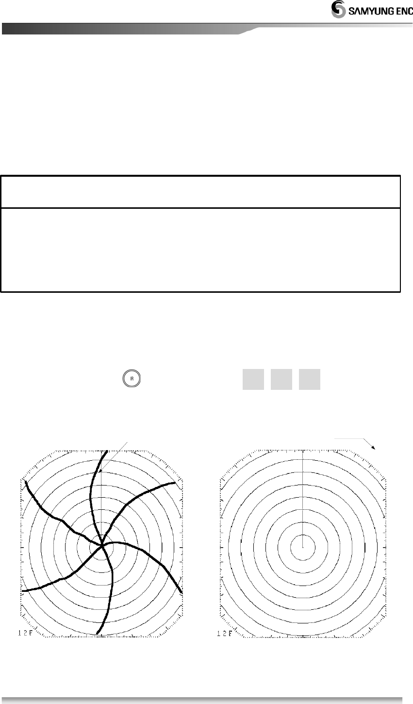
5. Radar interference
If there is any radars closely located that uses the same frequency, the
interference image by the radar appears on PPI screen. This interference turns
into various spots and appear in forms of many images but as the interference
does not appear in the same place, it can be distinguished from target image.
For the radar interference(‘ ’ button), select『ON』in the function to diminish or
get rid of it
39
Chapter 5. Installation
!
5.1 Overview
• Proper installation of Radar ensures the performance and safety of it during
operation and facilitates the maintenance and repair of it, you should carefully pay
attention to the proper of installation accoding to the instruction.
• Antenna should be installed as high as possible after considering its weight.
• Indicator should be installed inside Wheel House in order make observation
efficiently.
• 15m standard cable should be used between Antenna and Indicator.
5.2 Installation of Antenna
5.2.1 Selection of the installation place
!
*The specialist from Head Office or Local distributor should carry out installation work.
* Installation works carried out by unauthorized person can cause out of order,
performance failure Electric shock.
CAUTION
※ The place where there is no big obstructions on the level of ship’s fore and afterside.
※ If there is a obstacle on the same level of Antenna, it may cause a virtual image.
※ Especially when the virtural image appears on ship’s fore and after side, it will be
difficult to observe and hardly forecast the danger.
※ The place where there is a near Funnel can cause the decrease in performance, the
defect dueto haet, therefore it should be installed away from such Funnel as far as
possible.
※ Please keep in mind that Direction finding Antenna and VHF antenna should be far
away from Radar Antenna.
(Please avoid the situation from tying up said cables with Radar one)
Caution

40
5.2.2 How to install Antenna
1. Take a caution when antenna is installed on High Speed Vessel
Generally the head of High Speed Vessel will be up float when ship is in full speed.
Due to
this, in case the Antenna being installed in even level and trim (angle of ship’s stem
while running) being over 1/2 of vertical beam width (θ), the Echo from this target is
hardly displayed as image because the front of the ship is off the beam range that
causes the electric wave reflecting from the target becomes weak. In opposition, at
the stern of the ship the wave reflecting from the sea surface becomes strong. It will
not affect the image at the port and starboard side of the ship.
Therefore, in case the ship that of trim is over 1/2 of vertical beam width (θ), it is
recommended to install the Antenna in slant toward the ship’s stem.
2. Caution while the Antenna is installed in Yaucht
It is apt to be sliding in slant toward the counter windy side while the yaucht is
navigating when the wind is blowing to the extent. In case the slanted angle being
over 1/2 of beam width, the electric wave reflecting from the target becomes weak
since the ship structure is off the range of beam and Echo from this target is hardly
displayed as an image. In opposiiton, the opposite side of the wind, surface
reflecting becomes strong since the electric wave contacting sea surface becomes
strong. It will hardly affect the images of fore and after side of ship.
Therefore, in case Yaucht that of slant is over 1/2 of vertical beam width (θ), it is
recommended to install the mounting bracket in order that antenna can be slanted in
right and left side according to the angle of slant.
41
5.2.3 Connection to Equipment Cable
1. Scanner (RSU-3700)
※ Don’t bend the connector too much when input the cable into the Radome for preventing
from the damage
Caution
42
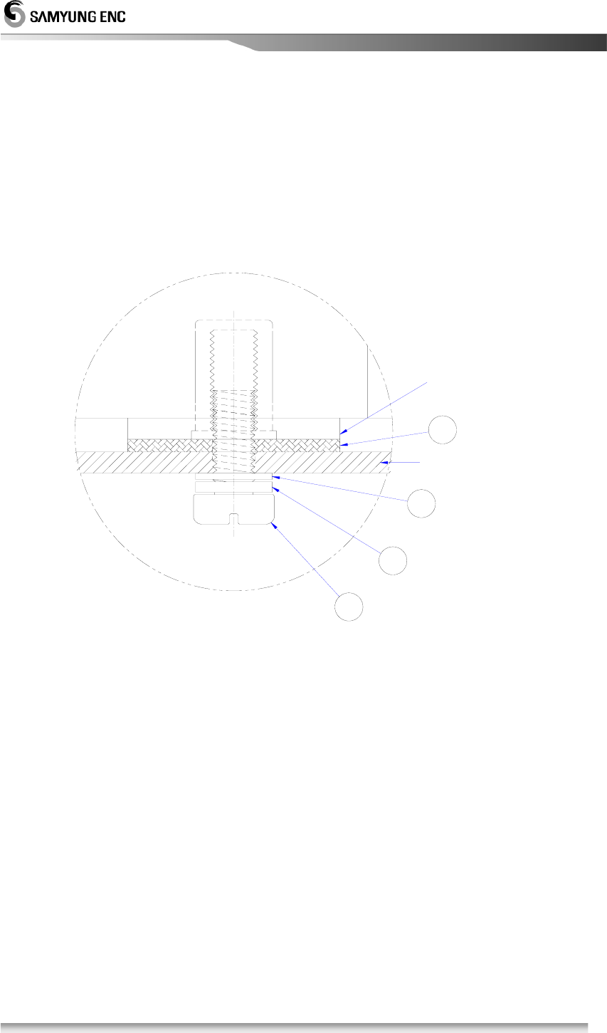
1
2
3
4
① Hexagonal Bolt ( Φ10 X 25mm )
② Spring Washer ( Φ10 )
③ Plain Wahser ( Φ10 )
④ Rubber Pad for fix-up a radome
Refer to No.1: Use less than 5mm in a radome fix-up panel.
In case of over 5mm, hexagonal bolt should be changed for installation.
Bottom of Scanner
Refer to No.1
43
5.3. DISPLAY SET-UP
5.3.1. Location for installation
• Select the location for easy-investigation and maintenance.
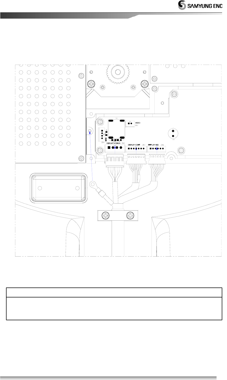
5.3.2 How to Install
(1) Install the display according to the Block Diagram.
(2) Refer to the installation diagram.
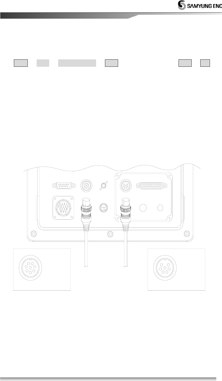
5.3.3. Power Cable connection
(1) Connect a Power cable to [POWER] of the back-pannel.
(2) Connect an Aireal-cable to [SCANNER] of the back-pannel.
(3) Connect an earth cable to [EARTH] of the back-pannel.
5.4. Installation check
• After installation, check weather the condition is O.K based on the instruction. The serious
check points are the cable connection, tight connection of each units, aireal-cable, the
connection of cable shield.
5.5. Operation check
(1) Before the operation check, it needs to check if the internal voltage is in an acceptable
voltage range.
(2) Check all parts of the radar in detail after operation check.
(3) Readjustment should be according to the manual even though the operation check is
O.K.
※ A display must be installed far away over than 1 meter from a magnet compass.
※ It may be harmful to the magnet compass in case of closer installation.
ATTENTION
44
5.6. Initial Installation
• In case of a first time, it must be executed an initial adjustment.
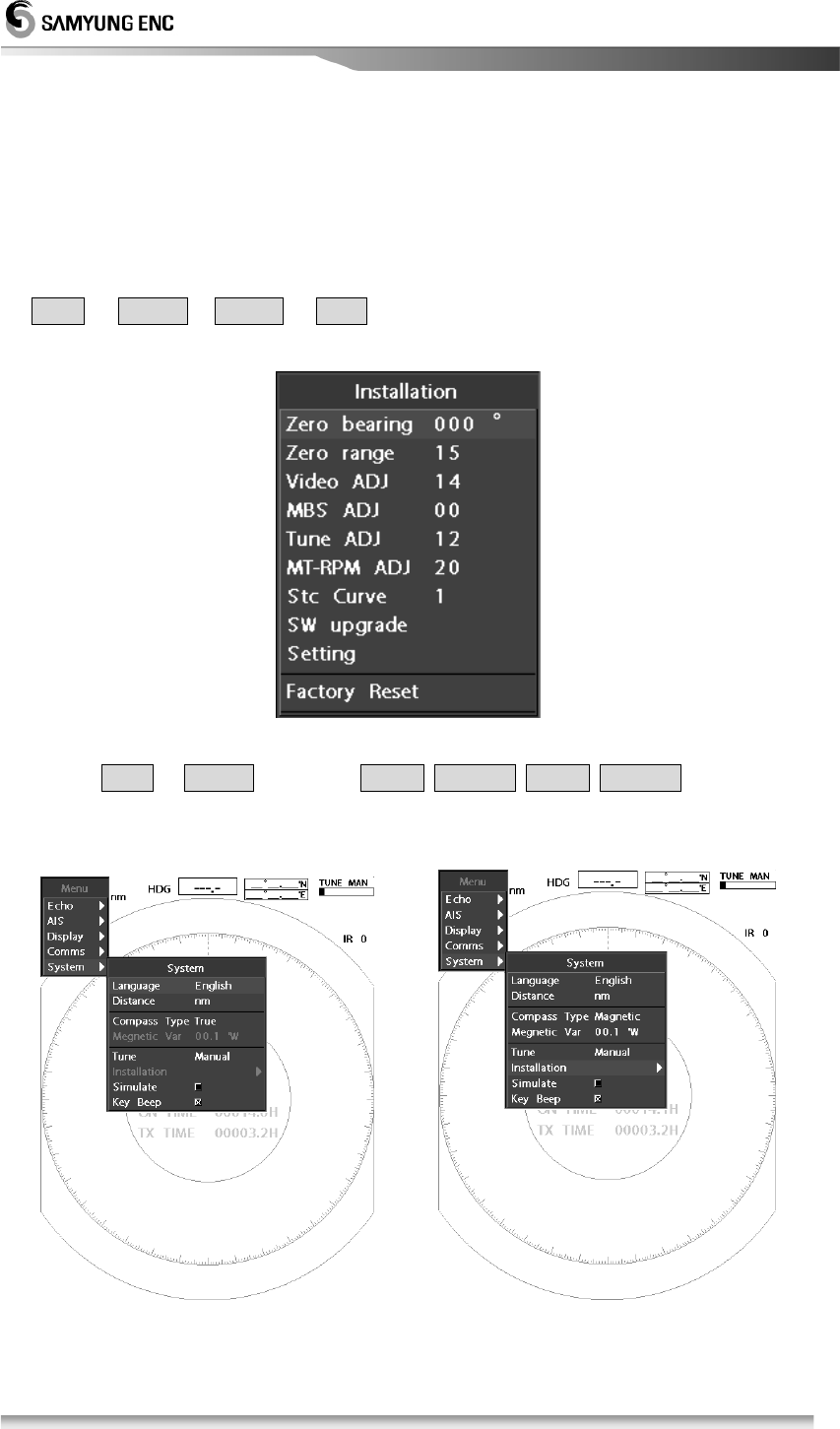
5.6.1 Initial Installation
Following is how to go to Initial setup menu
Menu Æ SystemÆ Int. Set Æ Enter after press these keys will show following
display.
※
Installation menu activate procdure:
At Menu in System list, press Cursor 중심이동 Cursor 중심이동 keys within 5
seconds then following screen will show:
[Screen before activation of installation menu] [Screen after activation of installation menu]
45
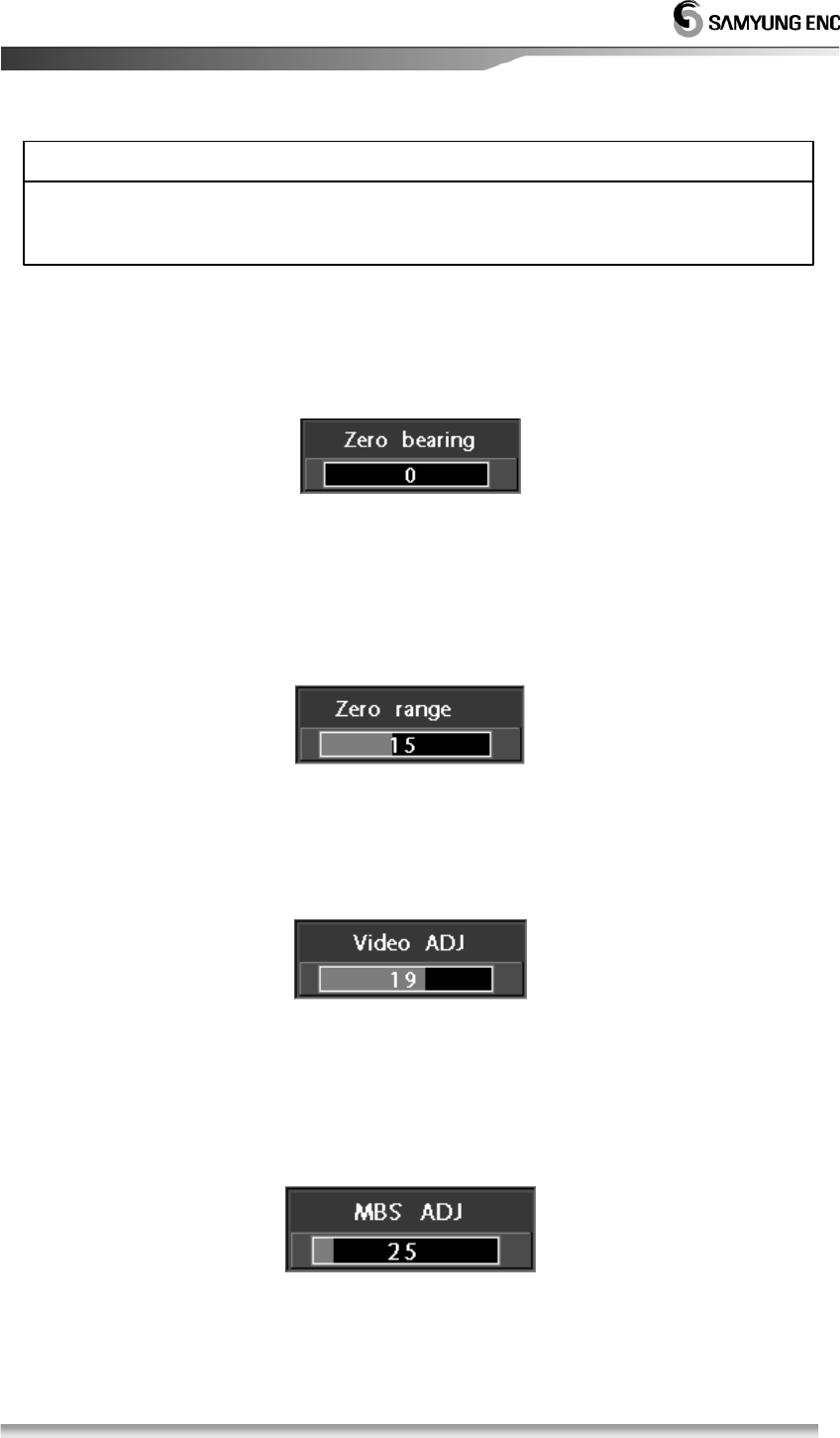
5.6.2 Bearing Adjustment
After installed the scanner, you can adjust vessel’s heading/bearing degree
from 0 ° to 360 ° degrees, and change it by 1° degree.
5.6.3 0 Mile Set
After installed the scanner, it depends on cable and/or device you can adjust a
real distance and target distance by adjusting 0 Milet Set menu. Control level is
devided by 36 different levels.
5.6.4 Video ADJ
After installed the scanner, it depends on calbe length video singal can be
adjusted and control level is devided by 36 different levels.
5.6.5 MBS (
Main Bang Suppression)
ADJ
It may be Main Bang phenomenon in a center of the indicator in a short range and can
be adjusted by 36 diffenet levels. If value is increased then Main Bang phenomenon
frequency will decrease.
※ The initial-setting should be executed in transmitting condition.
Without the initial setting, the target mark, distance and direction may be wrong.
ATTENTION
46
!
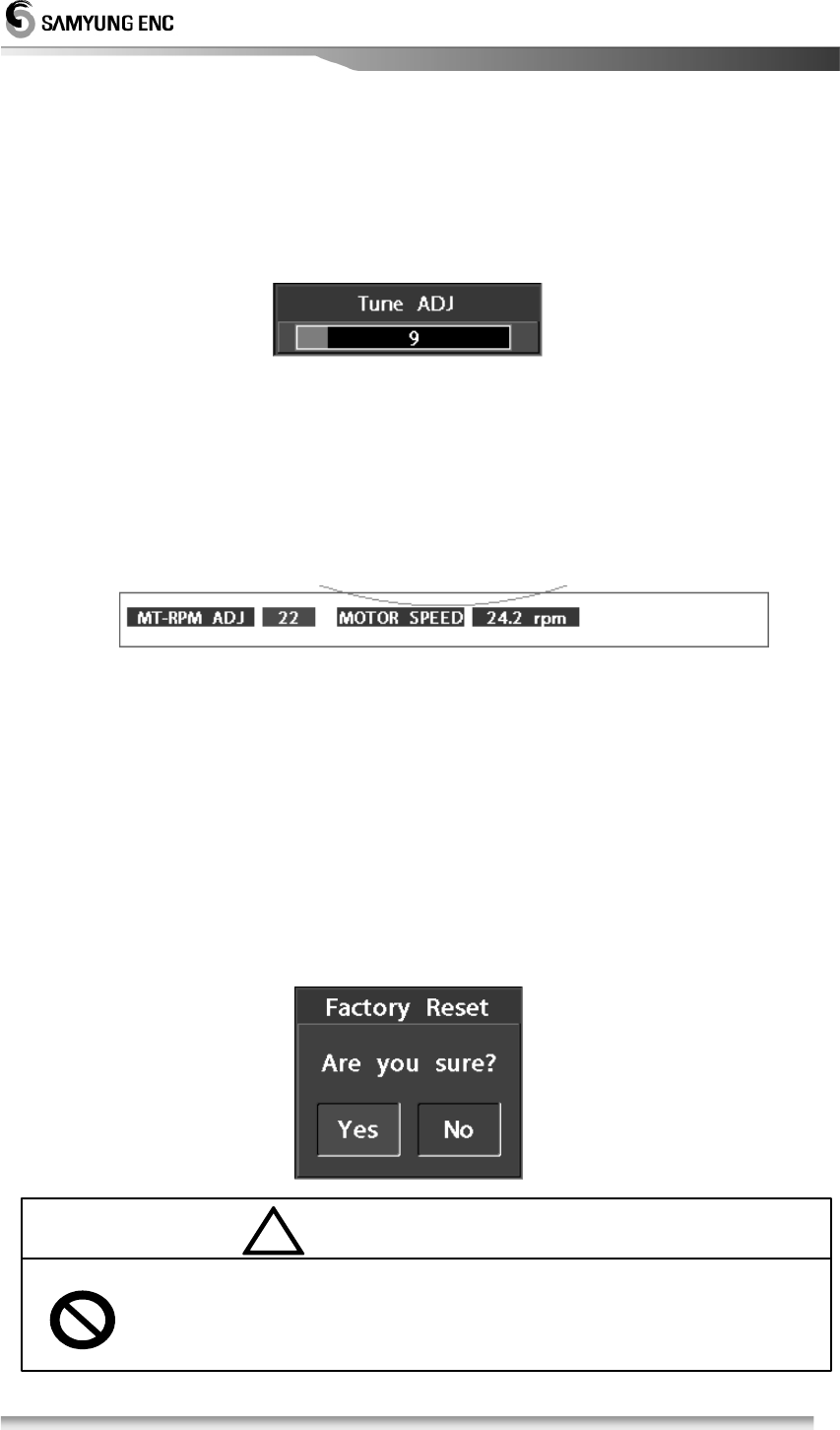
5.6.6 Tune ADJ
On the front, there is key control knob for Tunning and can be adjusted by 64
different levels.
For setting procudre, make Tune VR to the center and set target object and
Tune knob to the maximum.
5.6.7 MT-RPM ADJ
This is how to set for the scanner’s motor RPM.
Motor rotartion will display with RPM measurement, normal operatiing rotate
per minute is 24 RPM.
ATTENTION) When you operating in high speed then targeting object accuracy
will decrease and system speed can be decrease.
5.6.8 Software Upgrade
This menu will upgrade previouse software program.
5.6.9 Default manufacturing Setting
This menu will reset the default manufacturing settings.
ATTENTION) This menu is limited to use by end-users.
5.6.10 Default basic manufactreing set-up
This menu will reset devise to basic set up from the manufacuter.
]
ATTENTIO
Device came out with fully adjusted. For resetting for default basic
manufacture is limited to end-users. Not recomannding for adjusted by
end-users all the time.

47
Chapter 6. Maintenance
6.1. General Maintenance
(1) In order to get Radar performed in good order, a periodical maintenance should be done
properly.
(2) The unexpected troubles would be less by paying proper attention to timely maintenance.
(3) A common maintenance for each component is as follows.
6.1.1. Cleaning
(1) Do cleaning out the dust, salt water adhered to the unit.
(2) Cleaning with dry cloth.
6.1.2. Chect out the tightness of screw, bolt
• Check the tightness of screw or bolt, which attached on the unit.6
6.1.3. Check the cabling
• Check and maintanin the cabling between units periodically. (Scanner-Display, Display-
Power, Display-Option).
6.2. Scanner
• When maintained a wireline, cut off the power of monitor and then protect the power
supplied into the wireline. Don’t place watch or electronic card to the area of modulation,
which equips with Magnetron.
6.2.1. Radom
(1) In case Radome surface being contaminated by dust, paint, it may arise the attenuation
or reflection of electric wave and cause to decrease the performance of Radar, it should be
cleaned out by a soft cloth with alcohol to keep it cleaned at all times.
※ In case of the check of units, please make sure to turn off the power to protect from electric
shocking.
※ In case of using rectifier, cut off the power on monitor because it is still excited even Radar stopped.
ATTENTION

48
(2)
Check periodically the tightness of the attached bolts.
6.2.2. Bracket
• Check the mounting of scanner and do painting every half-year to prevent from being
rusted.
6.3. Display
6.3.1. Cleaning of a Display Screen
(1) In case a stain adhered to LCD screen, it deteriorates the transparency of LCD screen.
(2) Do cleaning with a soft cloth (100% cotton).
(3) Use antistatic agent but don’t rub it strongly.
※
Don’t use Benzene, Gasoline, Tricrene,
Keltone and any solvents other than alcohol.
CAUTION
49
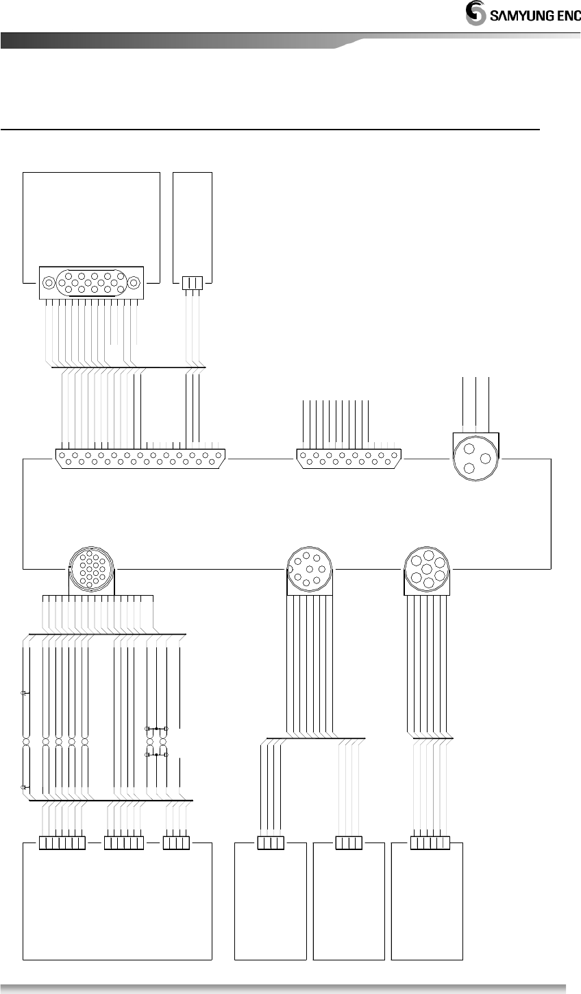
Chapter 7. Installation drawing and circuit diagram
1
(RSU-3700)
NMEA0183(HEADING)
RADAR SCNNER
15:+24VAWG20적색띠
5
갈색
3
VIDEO GND
VIDEO 1
2
흑색
흑색
흑색띠
흑색
RS485-A
RS485-B
TUNE-F
A-TUNE
GND
6
4
5
7
HEADING+
HEADING-
TRIGGER-
TRIGGER+
2
1
3
4
황색띠
황색
갈색띠
녹색띠
녹색
청색
청색띠
적색
5:TRIGGER+AWG26
SHIELD
75ohm
AWG26
AWG26
2:VIDEO GND
1:VIDEO
4:TUNE-F
3:A-TUNE
AWG26
AWG26
AWG26
AWG26
AWG26
AWG20
AWG20
AWG20
8:HEADING-
6:TRIGGER-
7:HEADING+
10:BEARING+
11:BEARING-
9:+0V
14:+24V
16:+0V
2
BEARING-
BEARING+
+24V
6
1
+0V
+24V
+0V
3
4
회색
백색
SHIELD
GND
NMEA RX
NMEA TX
+12V
AWG26
SHIELD
AWG26
전체 실드
12:RS485-A
SH:SHIELD
13:RS485-B
SH:SHIELD
SHIELD
V-SYNC
H-SYNC
SYNC-GND
SYNC-GND
B-GND
G-GND
R-GND
VGA_SW
MONITE_ON
VD-BLUE
VD-RED
VD-GREEN
V-SYNC (VGA-14)
12
15
DSUB-25P
3
1
2
SCC-25-16P
9
6
4
5
7
8
12
11
10
14
13
SCANNER
H-SYNC (VGA-13)
SYNC-GND (VGA-10)
MONITE_ON (VGA-09)
B-GND (VGA-08)
SYNC-GND (VGA-05)
VGA_SW (VGA-04)
G-GND (VGA-07)
VD-BLUE (VGA-03)
R-GND (VGA-06)
VD-GREEN (VGA-02)
VD-RED (VGA-01)
6
3
1
2
4
5
9
7
8
10
11
NC
NC
EXTENSION
VGA OUT:OPTION
SH
16
SCN-16-8R
24
18
15
13
14
16
17
GND
21
19
20
22
23
EXT_ALARM
+15V OUT
GND
NC
25
14
(OPTION)
1
2
8
4
3
5
7
6
6
11 1
11
10
9
13
12
15
10
5
VGA
ALARM ON시 EXT_ALARM PORT "LOWER" 출력
EXT-ALARM
EXT_ALARM
15
+15V
GND
NMEA2 RX
NMEA2 TX
NMEA1 RX
NMEA1 TX
NMEA0183(AIS)
NMEA0183(GPS)
AIS RX- AIS RX-
GND
NMEA RX
NMEA TX
+12V
+12V
AIS RX+
AIS TX-
AIS TX+
GND
+12V
GND
SHIELD
AIS TX-
GND
AIS TX+
+12V
AIS RX+
GND
DC INPUT
(10.8V~36V)
34
DOWNLOAD
DSUB-15P
7
4
3
2
6
5
8
NMEA0183
SCN-16-7R
2
1
3
5
4
6
61
572
(RS-422)
AIS
GND
11
SD_WP
5
2
1
3
4
SD_D1
SD_D0
SD_CD
SD_CLK
8
6
7
9
10
SD_CMD
SD_+3.3V
SD-GND
SD_D2
SD_D3
14
12
13
15
RADAR DISPLAY
SCN-20-3P
7
(10V~36V)
DC IN
(SMR-3700)
2:EARTH
13
1:+24V
1
2
2
3
3:0V
50
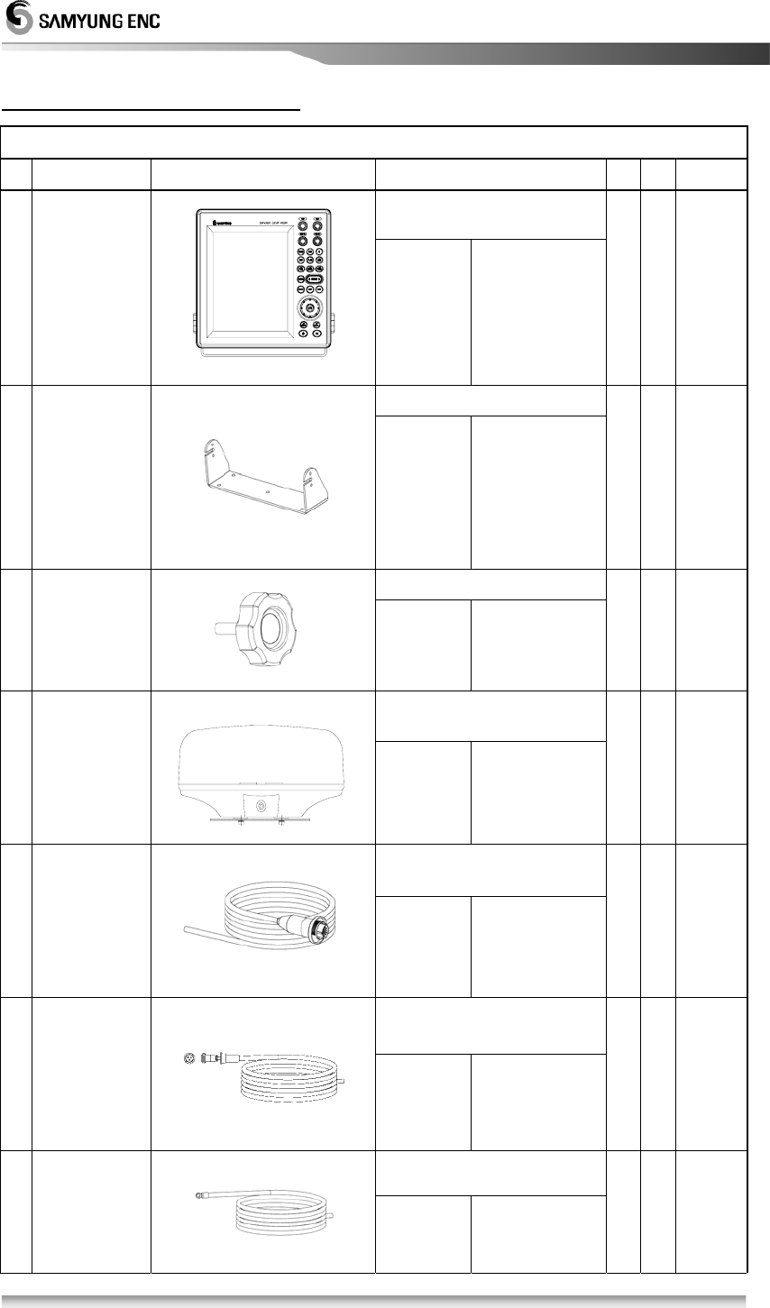
Chapter 7.Packinglist
SMR-3700 (36Mile Marine RADAR)
NO. Item External Drawing Dimension Qty Chk Remark
SMR-3700
1 Display
CODE NO. SMR-3700
1
2 Bracket
CODE NO. ACC-RADAR-
001
1
Ø6 × 20
3 Knob
CODE NO. ACC-6X18MM-
002
2
RSU-3700
4 Scanner
CODE NO. RSU-3700
1
SAMYUNG Ø11 X 16C
5
Scanner
Cable
CODE NO RSU-3700-15M
1
Cap
SRCN2A
25-16P
L=15m
CVV-SB2.0 SQ X 2C
6
Power
Cable
CODE NO. ACC-CAB-010
1
Cap
SCN20-
3P
L=3m
KIV 5.5mm2
7 Ground Cable
CODE NO. STR -595
1 L=3m
51
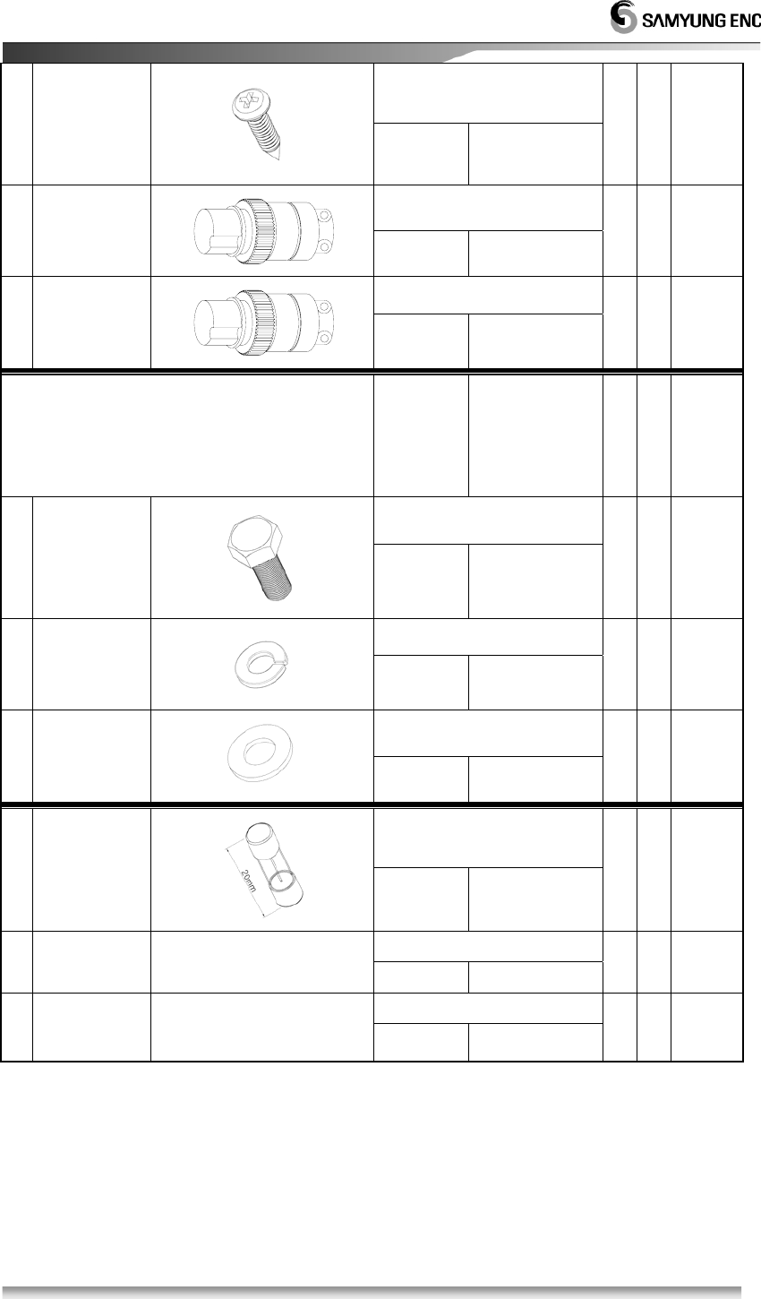
Ø4 X 16
8
Stainless
Piece
CODE NO. SPR-1407
5
SCN-16-7P
9 Connector,
7pin
CODE NO.
1
SCN-16-8P
10 Coonnector,
8pin
CODE NO.
1
RSU-3700
(Scanner Installation Material)
CODE NO. ACC-PAK-001
Ø10 X 25
11 Hexagon
Bolt
CODE NO. ACC-SC-001
4
Ø10
12
Spring
Washer
CODE NO. ACC-WA-001
4
Ø10
13
Flat
Washer
CODE NO. ACC-WA-002
4
7A
14 Fuse
CODE NO. ADD-FUSE-001
2
15 Manual
CODE NO. SMR-3700-MK 1
16
Scanner
Dwg.
Install’n
CODE NO. RSU-3700-DK
1
*Note: This user manual shall remain our property. They may not without our written
consent, either in their original state or with any changes, be copied or reproduced,
disclosed to or delivered to anyone unauthorized nor used for other purposes than
what has been confirmed by SAMYUNG ENC in writing. SAMYUNG ENC CO.,LTD.

52
Note: This equipment has been tested and found to comply with the limits for a Class
A digital device, pursuant to part 15 of the FCC Rules. These limits are designed to
provide reasonable protection against harmful interference when the equipment is
operated in a commercial environment. This equipment generates, uses, and can
radiate radio frequency energy and, if not installed and used in accordance with the
instruction manual, may cause harmful interference to radio communications.
Operation of this equipment in a residential area is likely to cause harmful interference
in which case the user will be required to correct the interference at his own expense.