SDG Systems IOT180 Media digital player box User Manual Manual
SDG Systems, LLC Media digital player box Manual
Manual
Shenzhen Smart Device Technology Co.,Ltd
Web: www.smdt.com.cn Tel: 0755-61662980 Fax:0755-26992201
IOT-180 V1.1
Digital Signage Board
Specification
Doc. Modification History
Version
Description
Date
V1.1
Creation
2016-11-29

Shenzhen Smart Device Technology Co.,Ltd
Web: www.smdt.com.cn Tel: 0755-61662980 Fax:0755-26992201
Catalogue
Chapter 1 Production General Description ................................... 错误!未定义书签。
1.1 General Description ............................................... 3
1.2 Features ......................................... 错误!未定义书签。
1.3 Appearance And Interface Sketch .................................. 4
Chapter 2 Basic Function List ............................................................................................. 6
Chapter 3 PCB Measurement And Interface Layout ..................................................... 8
3.1 PCB Measurement Chart ........................................... 8
3.2 Infterface Parameter Definition ..................................... 9
Chapter 4 Electric Performance ....................................................................................... 20
Chapter 5 Assembly Using Notice................................................................................... 21

Shenzhen Smart Device Technology Co.,Ltd
Web: www.smdt.com.cn Tel: 0755-61662980 Fax:0755-26992201
Chapter 1. Production General Description
1.1 Scope of Application
IOT180 belongs to commercial display smart mainboard ,
generally applicable to:advertising machine、digital signage、smart
self-service terminal、smart retail terminal、O2O smart device etc.
1.2 General Description
IOT180 uses Allwinner R18 Cortex-A53 quad core 64bit CPU,
carries Android 6.0 system,main frequency 1.5GHz,outstanding
Properties,affordable pricing,it is the most cost performance for
quad core.Using Mali400MP2 dual core super high performance
GPU,support HDMI 4K output,it is the best choice for your
advertising machine、smart terminal、industrial projects.
1.3 Features
◆ Quad core 64 bit CPU carries Android 6.0 system,it is the most
cost performance quad core board at present.
◆ Support HDMI 4K drive screen,support 4K video decoding,
bring the real sense of ultra clear visual enjoyment.
◆ Support HDMI and LVDS double screen same display、double

Shenzhen Smart Device Technology Co.,Ltd
Web: www.smdt.com.cn Tel: 0755-61662980 Fax:0755-26992201
screen different display,horizontal and vertical screen free
switch.
◆ Support EMMC 5.0,experience the most rapid storage speed.
◆ Support Android system customization,provide system debug
interface API reference code,perfect support customers upper
application APP development.
◆ Support remote、SD card/TF card、PC etc variety of upgrade
mode,SD card/TF card configure screen parameter,plug and
bright,perfect support each size and each resolution LVDS
display screen.
◆ Ample extended interfaces.5 USB ports(3 sockets,2 standard
USB ports),2 extensible TTL serial port,3 channels 232 serial
port,GPIO/ADC interface,satisfying requirement of variable
peripherals in the market.
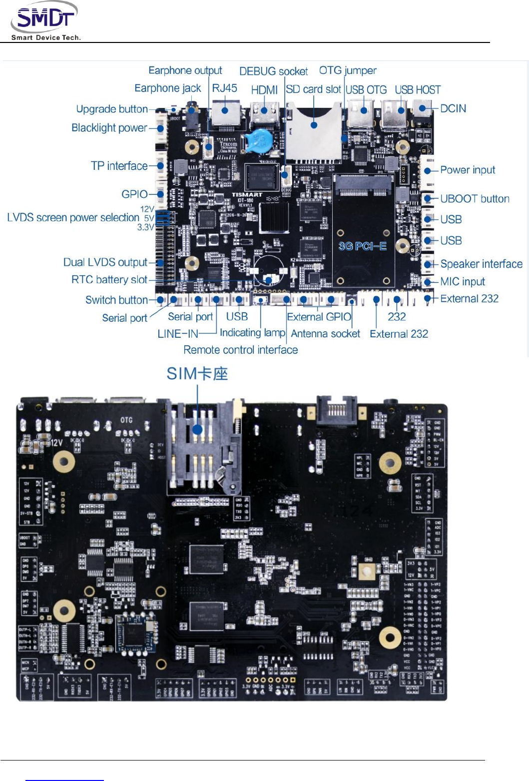
1.4 Appearance and Interface Sketch
Front/back:
Shenzhen Smart Device Technology Co.,Ltd
Web: www.smdt.com.cn Tel: 0755-61662980 Fax:0755-26992201

Shenzhen Smart Device Technology Co.,Ltd
Web: www.smdt.com.cn Tel: 0755-61662980 Fax:0755-26992201
Chapter 2. Basic Function List
Main Hardware Index
CPU
R18,quad core,main frequency 1.5GHz
Internal
Memory
LPDDR3 1G/2G (4 pcs 8 bit DDR3)
Built-in
Memory
EMMC 5.0 4/8/16/32G(optional)
Built-in ROM
4KB EEPROM
Decoding
Definition
Maximum support 4k 3840*2160
Operating
System
Android 6.0
Play Mode
Support loop, timing, inter-cut and variable play modes
Network
Support
Ethernet、support WiFi
wireless peripheral
extension
Video Playing
Support wmv、avi、flv、rm、rmvb、mpeg 、ts、mp4 etc.
Image Format
Support BMP、JPEG、PNG、GIF
USB2.0 Ports
3 USB HOST sockets、2 USB A type socket(including 1
OTG)
Serial Port
2 TTL serial port sockets,3 232 serial port sockets
Shenzhen Smart Device Technology Co.,Ltd
Web: www.smdt.com.cn Tel: 0755-61662980 Fax:0755-26992201
GPS
External GPS(optional)
WIFI
Built-in WIFI
Ethernet
1,10M/100M self-adapting Ethernet
SD Card
SD Card
LVDS Output
1 single/double channel,can drive 50/60Hz LCD panel
directly
HDMI Output
1,support 4K output
Audio And
Video Output
Support left and right channels output, built-in dual
4R/20W,8R/10W amplifier
RTC Real Time
Clock
Support
Timing Switch
Support
System
Upgrade
Support local SD,USB upgrade
Shenzhen Smart Device Technology Co.,Ltd
Web: www.smdt.com.cn Tel: 0755-61662980 Fax:0755-26992201
Chapter 3 PCB Measurement And Interface
Layout
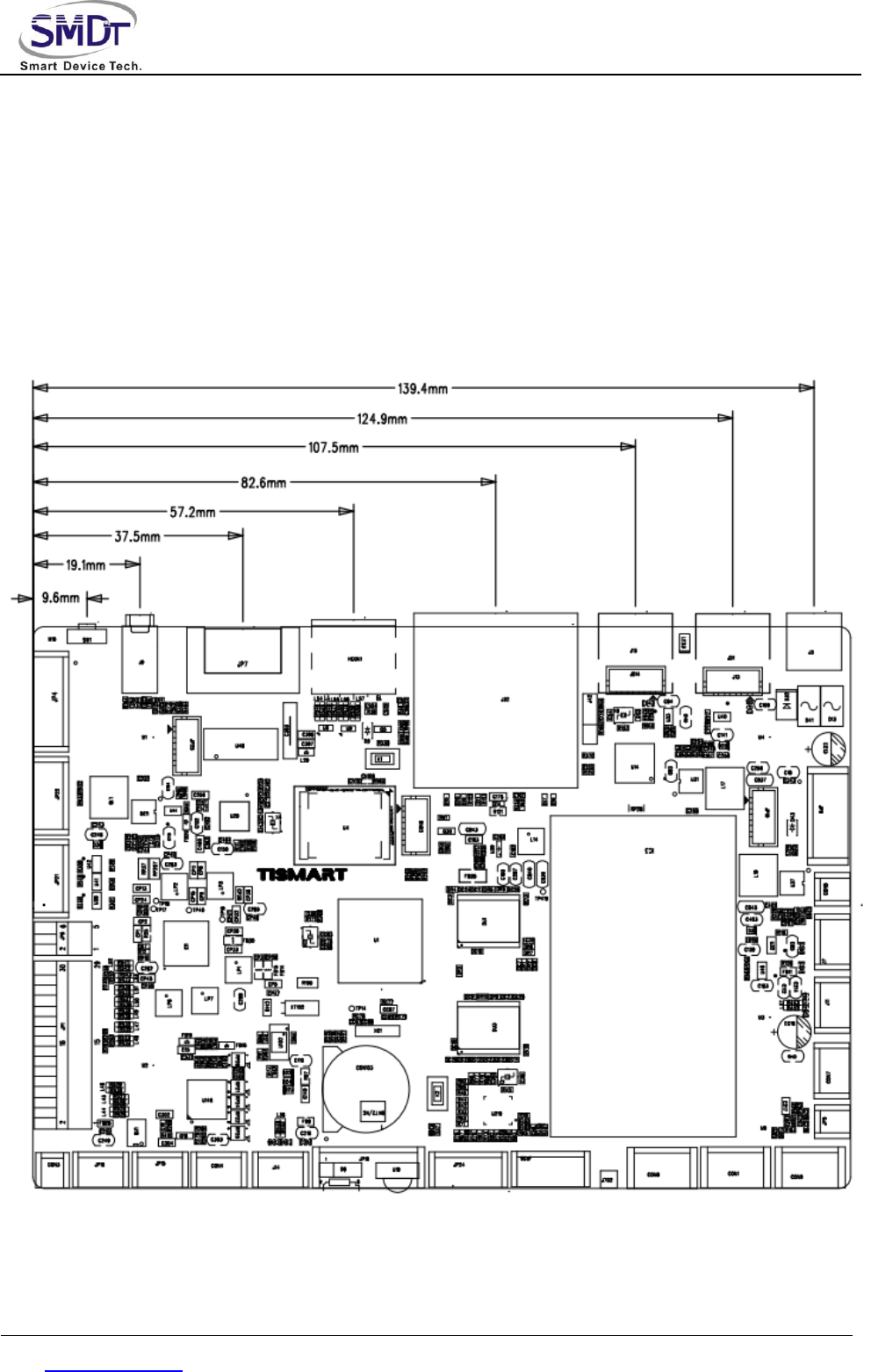
3.1 PCB Measurement Chart

Shenzhen Smart Device Technology Co.,Ltd
Web: www.smdt.com.cn Tel: 0755-61662980 Fax:0755-26992201
PCB:6 layers
Measurement:146mm*100mm, thickness 1.6mm
Screw hole specification:∮3.2mm x 4
3.2 Interface Parameter Definition
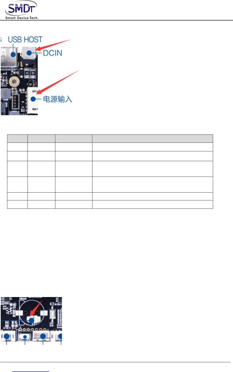
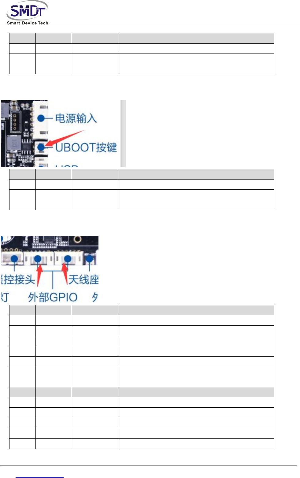
◆Power Input Port
Use 12V DC power supply,only allowed from the DC power supply and power socket to power the board
system,the plug of the power adapter DC IN specifications is D6.0,d2.0. without in a peripheral empty load
cases,12V dc power supply to support the minimum current 600 mA.
Shenzhen Smart Device Technology Co.,Ltd
Web: www.smdt.com.cn Tel: 0755-61662980 Fax:0755-26992201
Power socket interfaces are defined as follows,can use power panel power supply,the socket specifications is
6 pin 2.54 mm spacing.
NO.
Definition
Property
Description
1
VCC
input
12V input
2
VCC
input
12V input
3
GND
ground
electrode
ground electrode
4
GND
ground
electrode
ground electrode
5
VCC-5V
input
standby 5V input
6
STB
output
standby signal output
Standby 5V input & standby signal output is used as standby power supply board,if want to do low standby
power consumption,the standby 5V input & standby signal output signal respectively connected with the 5 v
power supply board STB and PS_ON(the description of the two signals might be different from different
suppliers of power supply board,Please refer to the actual), If you don't need to do low standby power
consumption,then no need to connect the 2 pins.
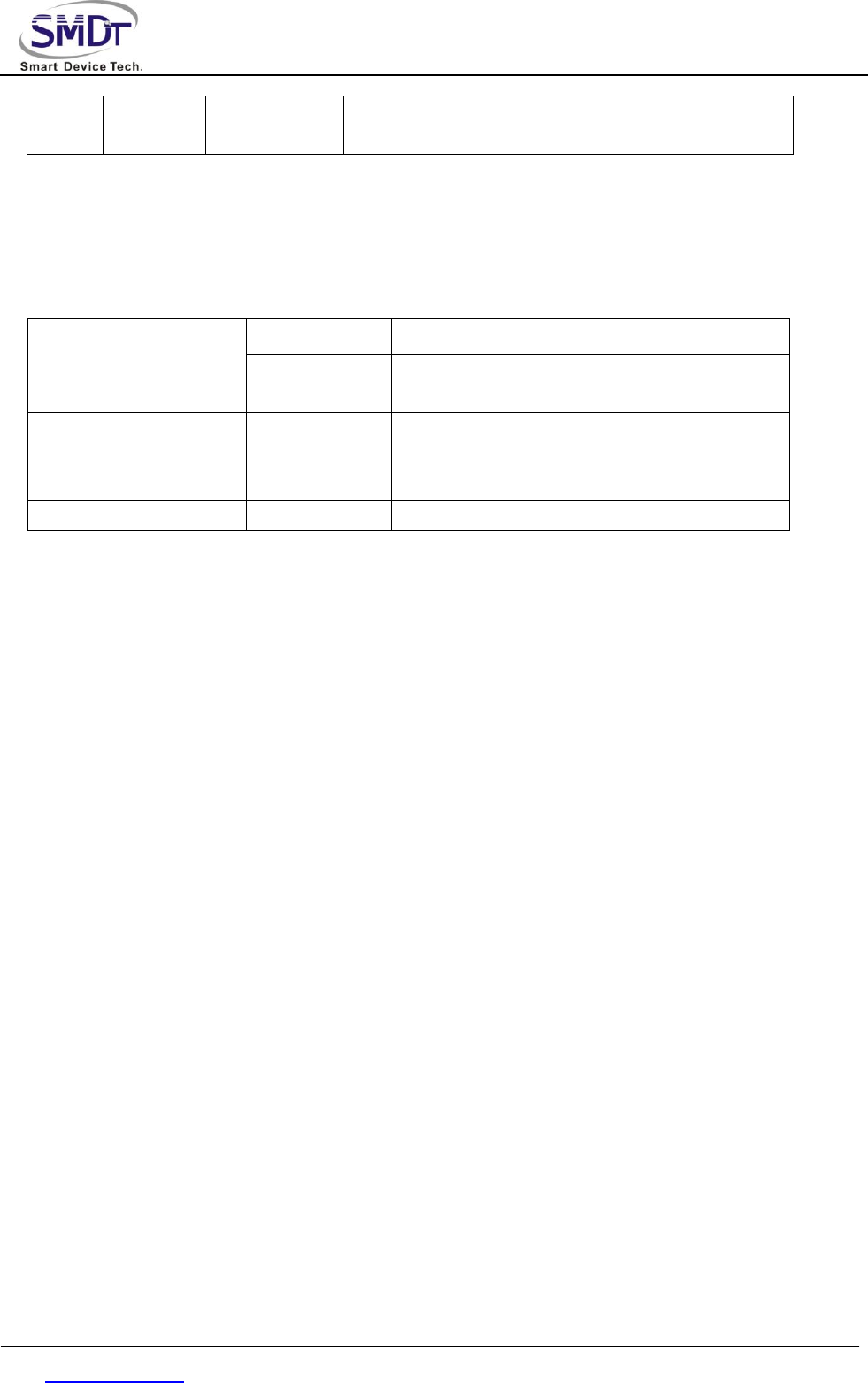
◆ BAT1 RTC Battery Port
Used to install the clock battery,supply power to the system clock when power outages.
Shenzhen Smart Device Technology Co.,Ltd
Web: www.smdt.com.cn Tel: 0755-61662980 Fax:0755-26992201
NO.
Definition
Property
Description
1
RTC
input
3V input
2
GND
ground
electrode
ground electrode
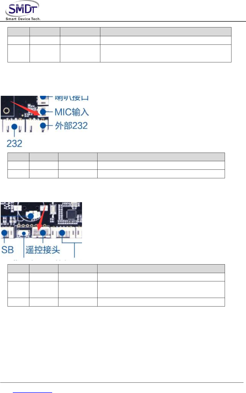
◆ MIC Port
Please note that the MIC is positive negative connection,not reverse.
NO.
Definition
Property
Description
1
MIC-
input
MIC-
2
MIC+
input
MIC+
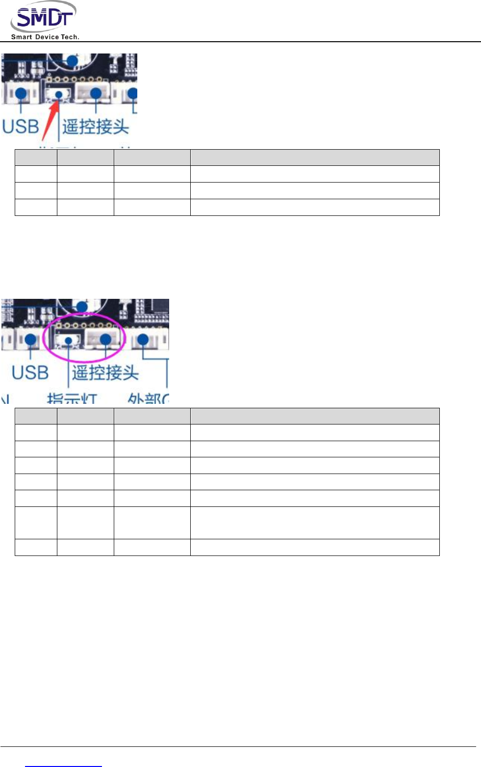
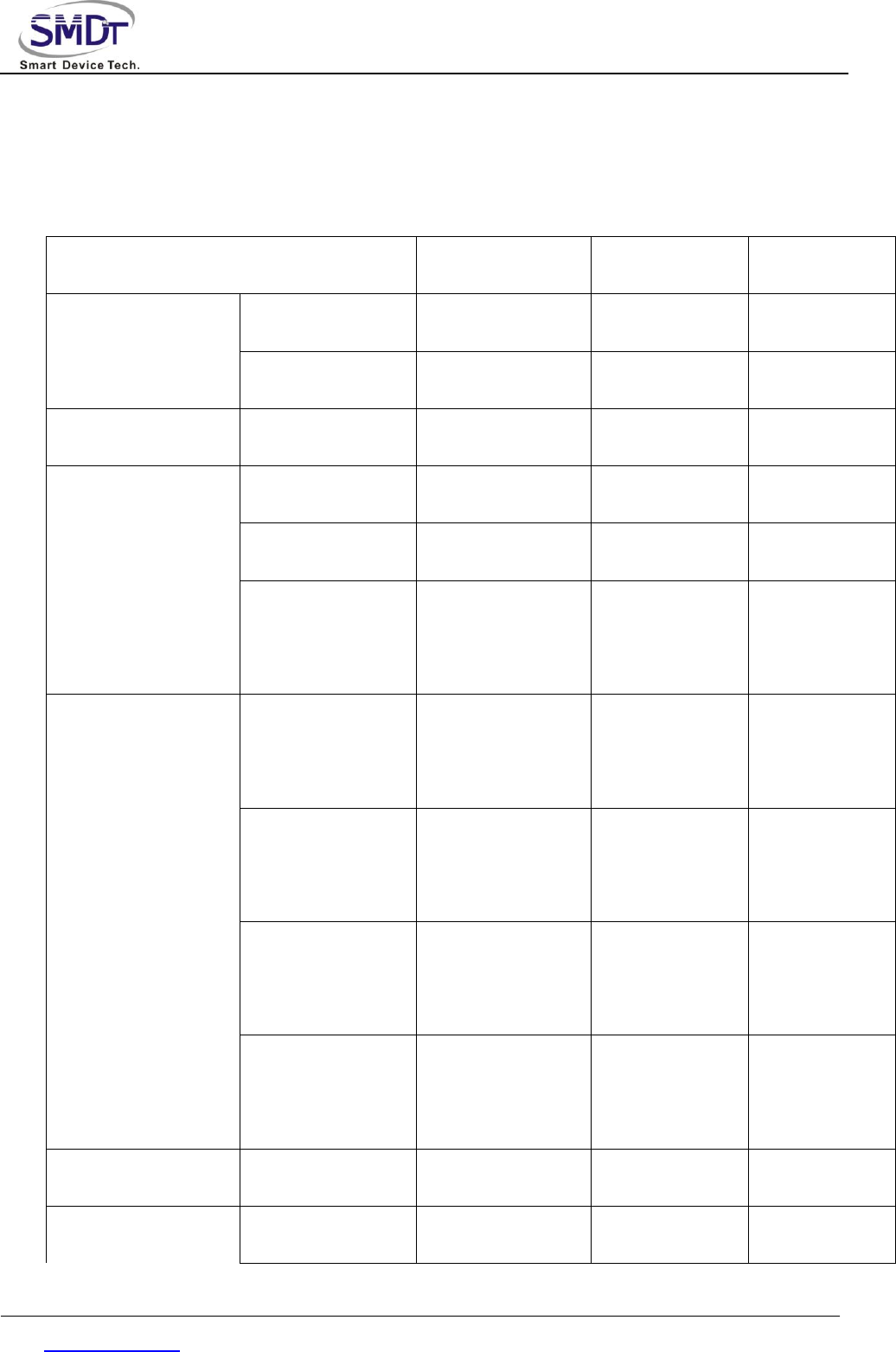
◆ Port Of Receiving Remote Control
NO.
Definition
Property
Description
1
IR
input
remote control signal input
2
GND
ground
electrode
ground electrode
3
3V3
Power
3.3V output
◆ Work Indicating Lamps
The default support gongyang red blue double LED lights.
Shenzhen Smart Device Technology Co.,Ltd
Web: www.smdt.com.cn Tel: 0755-61662980 Fax:0755-26992201
NO.
Definition
Property
Description
1
LED_B
blue lamp
work indicating lamp
2
VCC
power
3.3V output
3
LED_R
red lamp
standby indicating lamp
◆ LED/IR Port
The position of remote control receiving and indicating light is shared(can choose welding 2.54 mm spacing of
7 pins socket)
NO.
Definition
Property
Description
1
LED_B
output
work indicating lamp
2
VCC
power
3.3V output
3
LED_R
output
standby indicating lamp
4
ADC
ADC input
ADC button input
5
IR
input
remote control signal input
6
GND
ground
electrode
ground electrode
7
3.3V
power
3.3V output
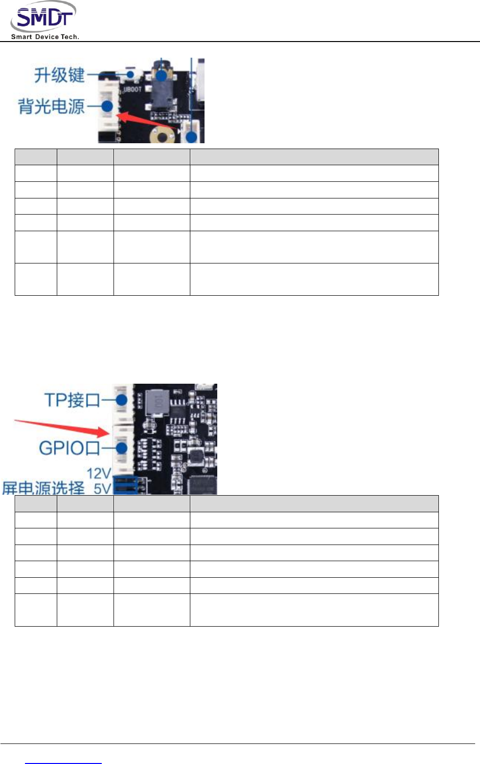
◆ Backlight Control Port
Use for LVDS screen backlight control,the 12V power supply current is not more than 1.5A,When using more
than 19 inch screen or screen backlight power in more than 20W,backlight power supply electricity is taken
from the other power plate,so as not to cause system instability.Backlight can make voltage is 5V,if other
voltage, please add IO level conversion circuit. The 12V power supply only as a backlight power output,
don't as a power input supply system.
Shenzhen Smart Device Technology Co.,Ltd
Web: www.smdt.com.cn Tel: 0755-61662980 Fax:0755-26992201
NO.
Definition
Property
Description
6
VCC
power
12V output
5
VCC
power
12V output
4
BL-EN
output
backlight enable control
3
BL-ADJ
output
backlight brightness adjust control
2
GND
ground
electrode
ground electrode
1
GND
ground
electrode
ground electrode
◆ I/O Control Port
For provide peripherals with input/output for controlling signal.Electrical level is 3.3V,ADC signal can be used
for press key control.
NO.
Definition
Property
Description
1
VCC
power
3.3V output
2
I/O
input
GPIO-1
3
I/O
input
GPIO-2
4
I/O
output
GPIO-3
5
ADC
input/output
ADC signal
6
GND
ground
electrode
ground electrode
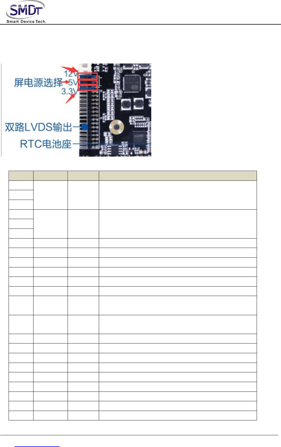
◆ LVDS Port
Commonly used LVDS interface definitions,support single/double channels,6/8 bits 1080P LVDS screen.
Screen voltage can be choose by jumper cap,can choose to support 3.3V/5V/12V screen power supply.
In order to avoid burning board and screen, please pay attention to the following:
Shenzhen Smart Device Technology Co.,Ltd
Web: www.smdt.com.cn Tel: 0755-61662980 Fax:0755-26992201
1.Please make sure the specifications and power supply voltage of the screen is correct,the power supply of the
board can meet the maximum current screen work accordingly
2.Please confirm the power of the jumper cap is correct by multimeter.
Using jumper cap to select the power of the screen above, from top to bottom,in order:12V/5V/3.3V.
NO.
Definition
Property
Description
1
PVCC
power
output
LCD power output,+3.3v/+5V/ +12V optional
2
3
4
GND
ground
electrode
ground electrode
5
6
7
0-VN0
output
Pixel0 Negative Data (Odd)
8
0-VP0
output
Pixel0 Positive Data (Odd)
9
0-VN1
output
Pixel1 Negative Data (Odd)
10
0-VP1
output
Pixel1 Positive Data (Odd)
11
0-VN2
output
Pixel2 Negative Data (Odd)
12
0-VP2
output
Pixel2 Positive Data (Odd)
13
GND
ground
electrode
ground electrode
14
GND
ground
electrode
ground electrode
15
0-VNC
output
Negative Sampling Clock (Odd)
16
0-VPC
output
Positive Sampling Clock (Odd)
17
0-VN3
output
Pixel3 Negative Data (Odd)
18
0-VP3
output
Pixel3 Positive Data (Odd)
19
1-VN0
output
Pixel0 Negative Data (Even)
20
1-VP0
output
Pixel0 Positive Data (Even)
21
1-VN1
output
Pixel1 Negative Data (Even)
22
1-VP1
output
Pixel1 Positive Data (Even)
23
1-VN2
output
Pixel2 Negative Data (Even)
Shenzhen Smart Device Technology Co.,Ltd
Web: www.smdt.com.cn Tel: 0755-61662980 Fax:0755-26992201
24
1-VP2
output
Pixel2 Positive Data (Even)
25
GND
ground
electrode
ground electrode
26
GND
ground
electrode
ground electrode
27
1-VNC
output
Negative Sampling Clock (Even)
28
1-VPC
output
Positive Sampling Clock (Even)
29
1-VN3
output
Pixel3 Negative Data (Even)
30
1-VP3
output
Pixel3 Positive Data (Even)
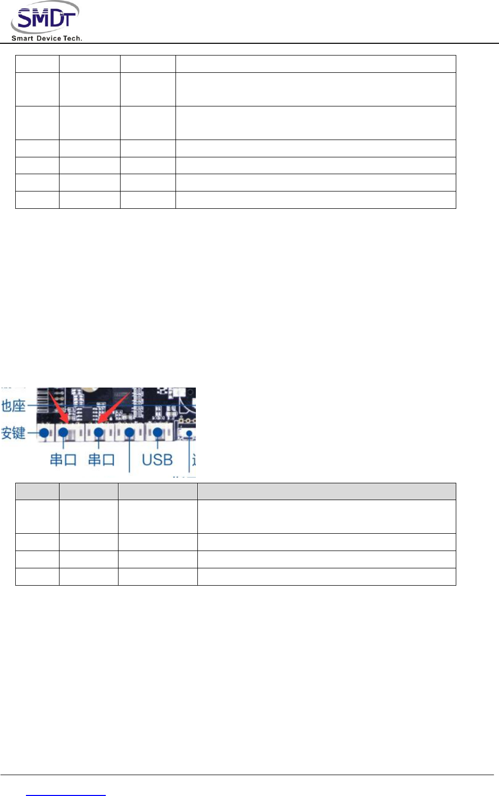
◆ TTL Double Wires Serial Socket Port*2
The board raises two common double wires of serial ports,can support general serial port devices on the
market,level of the serial port is 0V to 3.3V.If the abutting serial level higher than 3.3 V,must have the isolating
circuit or level conversion circuit, otherwise it will burn out master and equipment.
Notice:
1.If TTL serial port voltage can match or not, can't directly access MAX232,485 devices.
2.TX,RX connection if is correct.
NO.
Definition
Property
Description
1
GND
ground
electrode
ground electrode
2
UART- RX
input/output
RX
3
UART- TX
input/output
TX
4
VCC
power
3.3V output
◆ 232 Double Wires Serial Socket Port *3
Notice:
1.If 232 serial port voltage can match or not, can't directly access TTL,485 devices.
2.TX,RX of 232 connection if is correct.
Shenzhen Smart Device Technology Co.,Ltd
Web: www.smdt.com.cn Tel: 0755-61662980 Fax:0755-26992201
NO.
Definition
Property
Description
1
GND
ground
electrode
ground electrode
2
232-RX
input/output
232-RX
3
232-TX
input/output
232-TX
4
VCC
power
5V output
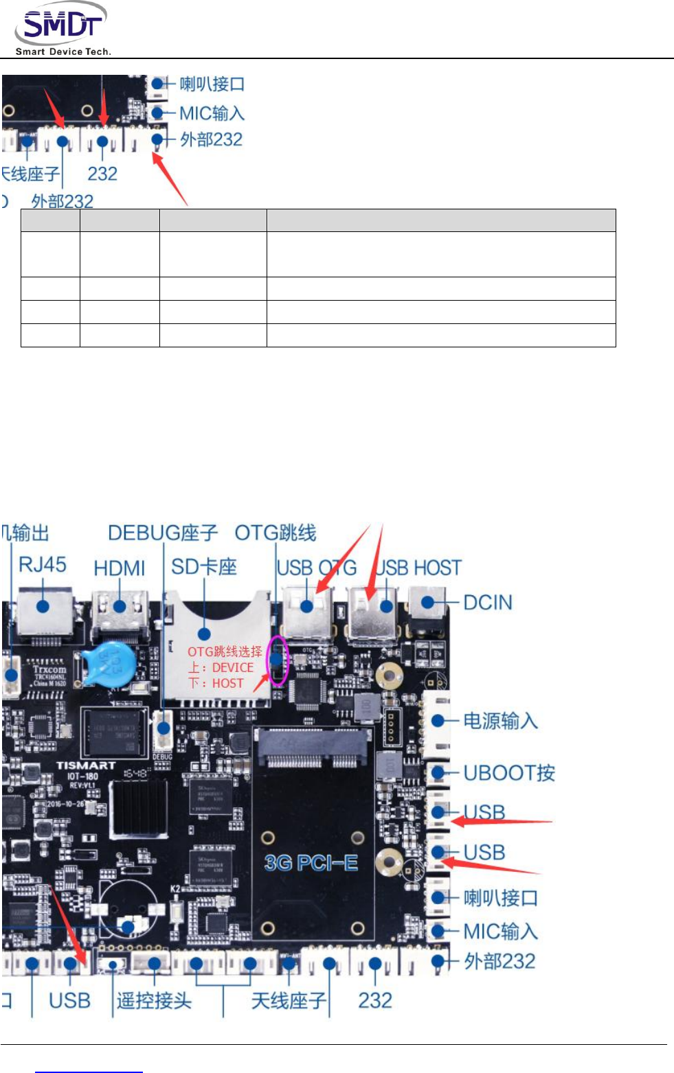
◆ USB
The board has 2 standard USB interface,including 3 inbuilt USB socket,can be used for peripheral expansion,
default to HOST,each interface power supply current is 900mA,for USB OTG interface,can select the
Host/Device by screen printing position and the jumper as below picture on the PCB board.
Shenzhen Smart Device Technology Co.,Ltd
Web: www.smdt.com.cn Tel: 0755-61662980 Fax:0755-26992201
NO.
Definition
Property
Description
1
VCC
power
5V output
2
DM
input/output
DM
3
DP
input/output
DP
4
GND
ground
electrode
ground electrode
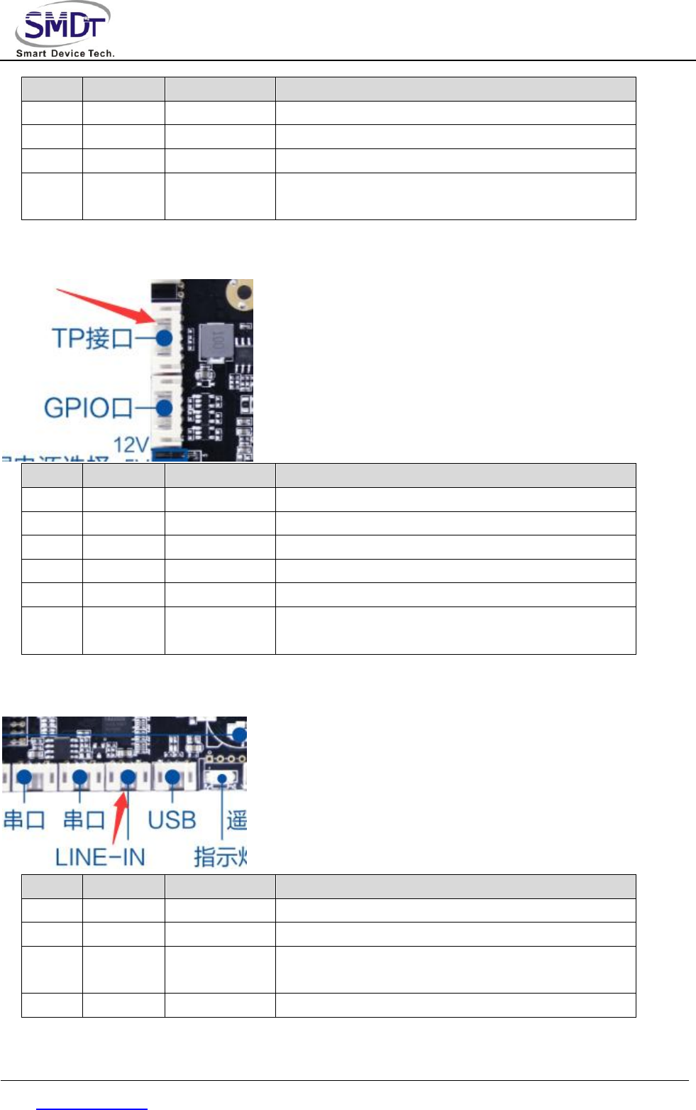
◆ Touch Screen Port
NO.
Definition
Property
Description
1
VCC
power
3.3V output
2
SCK
input/output
I2C clock
3
SDA
input/output
I2C data
4
INT
input/output
interrupt
5
RST
input/output
reset
6
GND
ground
electrode
ground electrode
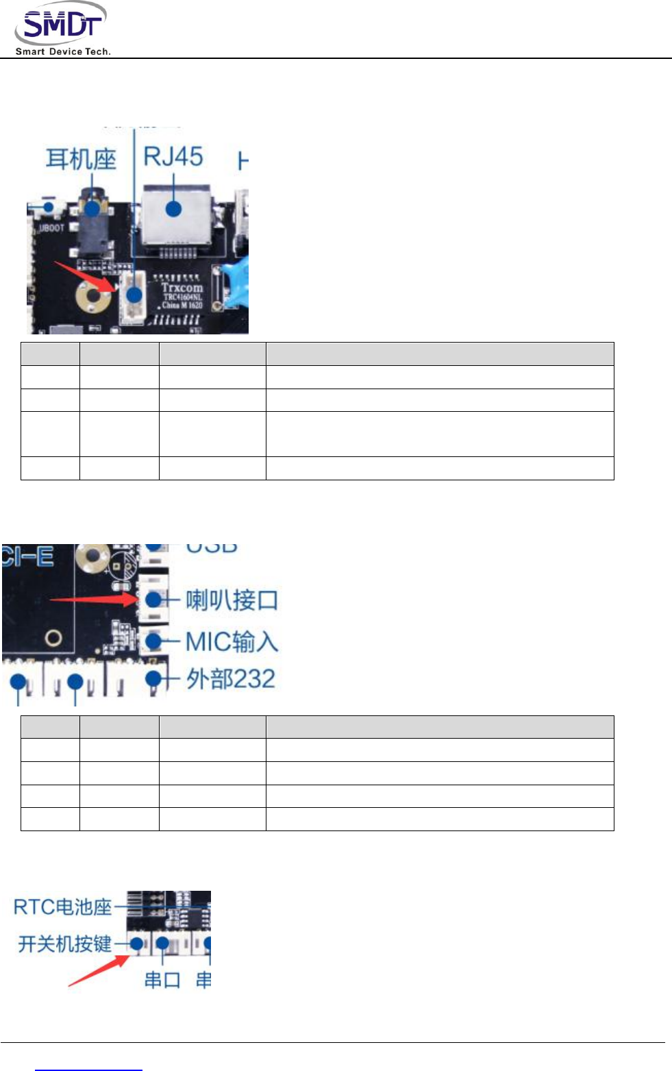
◆ LINE_IN Port
NO.
Definition
Property
Description
1
LIN
input
left channel audio input
2
RIN
input
right channel audio input
3
GND
ground
electrode
ground electrode
4
NC
disconnect
unused
Shenzhen Smart Device Technology Co.,Ltd
Web: www.smdt.com.cn Tel: 0755-61662980 Fax:0755-26992201
◆ Audio Port 1(External amplifier needed)
◆
NO.
Definition
Property
Description
1
AL
output
audio output left
2
HS-MIC
input
detect earphone input
3
GND
ground
electrode
ground electrode
4
AR
output
audio output right
◆ Audio Port 2(can drive loudspeaker directly)
NO.
Definition
Property
Description
1
OUTP-R
output
audio output right+
2
OUTN-R
output
audio output right-
3
OUTN-L
output
audio output left-
4
OUTP-L
output
audio output left+
◆ Switch Button Interface
Shenzhen Smart Device Technology Co.,Ltd
Web: www.smdt.com.cn Tel: 0755-61662980 Fax:0755-26992201
NO.
Definition
Property
Description
1
PWR-ON
input
external connect one pin of power button
2
GND
ground
electrode
external connect another pin of power button
◆ Uboot Upgrade Button Port
NO.
Definition
Property
Description
1
Uboot
input
external connect one pin of upgrade button
2
GND
ground
electrode
external connect another pin of upgrade button
◆ External GPIO
NO.
Definition
Property
Description
1
3.3V
power
3.3V output
2
GPIO0
input/output
GPIO0
3
GPIO1
input/output
GPIO1
4
GPIO2
input/output
GPIO2
5
GPIO3
input/output
GPIO3
6
GND
ground
electrode
GND
NO.
Definition
Property
Description
1
3.3V
power
3.3V output
2
GPIO4
input/output
GPIO4
3
GPIO5
input/output
GPIO5
4
GPIO6
input/output
GPIO6
5
GPIO7
input/output
GPIO7
Shenzhen Smart Device Technology Co.,Ltd
Web: www.smdt.com.cn Tel: 0755-61662980 Fax:0755-26992201
6
GND
ground
electrode
GND
◆ Other Standard Interfaces And Function:
Memory Port
SD/TF Card
data storage, maximum support 32G
USB
HOST port, support data storage, data input, USB,
mouse keyboard, camera, touch screen etc.
Ethernet Port
RJ45 Port
Support 100M wire network
HDMI Port
Standard Port
support HDMI data output, maximum support
1080P
Earphone Port
Standard port
3.5mm standard port
FCC Statement
This equipment has been tested and found to comply with the limits for a Class B digital device,
pursuant to Part 15 of the FCC Rules. These limits are designed to provide reasonable
protection against harmful interference in a residential installation. This equipment generates
uses and can radiate radio frequency energy and, if not installed and used in accordance with
the instructions, may cause harmful interference to radio communications. However, there is
no guarantee that interference will not occur in a particular installation. If this equipment does
cause harmful interference to radio or television reception, which can be determined by turning
the equipment off and on, the user is encouraged to try to correct the interference by one or
more of the following measures:
-- Reorient or relocate the receiving antenna.
-- Increase the separation between the equipment and receiver.
-- Connect the equipment into an outlet on a circuit different from that to which the receiver is
connected.
-- Consult the dealer or an experienced radio/TV technician for help.
This device complies with part 15 of the FCC Rules. Operation is subject to the following two
conditions:(1) This device may not cause harmful interference, and (2) this device must accept
any interference received, including interference that may cause undesired operation.
Changes or modifications not expressly approved by the party responsible for compliance
could void the user's authority to operate the equipment.
This equipment complies with FCC radiation exposure limits set forth for an uncontrolled environment.
This equipment should be installed and operated with minimum distance 20cm between the
radiator & your body.
Shenzhen Smart Device Technology Co.,Ltd
Web: www.smdt.com.cn Tel: 0755-61662980 Fax:0755-26992201
Chapter 4. Electric Performance
Project
Min
Typical
Max
Power voltage
voltage
--
12V
--
ripple wave
--
--
50mV
Power voltage
current
3A
Power current
(HDMIoutput,no
other peripheral)
working current
--
300mA
500mA
standby current
--
17mA
20mA
USB power
supply current
--
--
900mA
Power current
(LVDS)
3.3V working
current
400 mA
500 mA
5V working
current
550 mA
1A
12V working
current
580 mA
1A
USB power
supply current
--
--
900mA
Total output
current
3.3V
800mA
Environment
Relative
--
--
80%

Shenzhen Smart Device Technology Co.,Ltd
Web: www.smdt.com.cn Tel: 0755-61662980 Fax:0755-26992201
humidity
working
temperature
-20℃
--
70℃
Remark 1:When connect the LVD screens,need to pay attention to select the right
backlight working voltage 3.3V, 5V, 12V,the users cannot be applied to beyond the
corresponding maximum current peripherals.
Remark 2: When connect the LVD screens,the board of the whole working current
and standby current depending on the connection screens,above form not listed.
Chapter 5 Assembly Using Notice
In the process of assembly use,please note the following points (and not limited to)
problem.
一, Bare board and a peripheral short circuit problem.
二, In the process of installing fixed,avoiding the bare board deformation
caused by fixed problems.
三, When connect the LVD screens,pay attention to the screen voltage, electric
current if is coincident. Attention to the problem of screen socket 1 pin
direction.
四, When connect the LVD screens,pay attention to the screen backlight
voltage, electric current if is coincident.The backlight power is more than

Shenzhen Smart Device Technology Co.,Ltd
Web: www.smdt.com.cn Tel: 0755-61662980 Fax:0755-26992201
20W, whether or not to use other power panel power supply.
五, Peripheral devices (USB, IO, etc) when installation,attention to the problem
of peripheral IO level and current output.
六, A serial port when installation,pay attention to whether connect 232,485
devices directly.TX,RX connection if is correct.
七, Whether the input power supply access on the power input interface,
according to the total peripheral evaluation ,whether can meet the
requirements of the input power supply voltage, electric current and so on.
To eradicate facilitate the operation from a backlight socket for access to
the power supply input power.