SEA COM SEA157S VHF Marine Radiotelephone/Class A DSC GMDSS User Manual OPR 157SA Rev1a
SEA COM CORPORATION VHF Marine Radiotelephone/Class A DSC GMDSS OPR 157SA Rev1a
SEA COM >
Contents
Users Manual
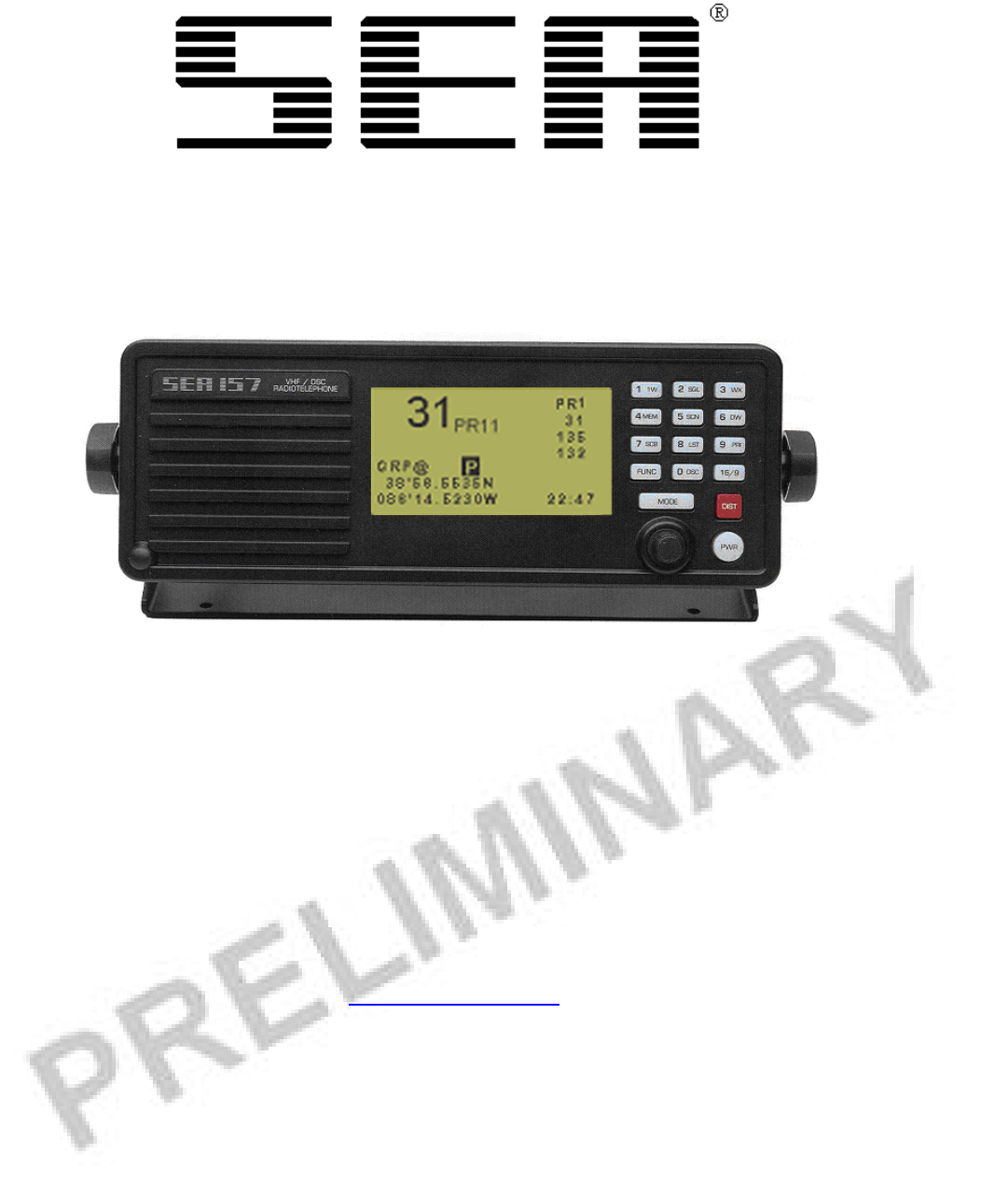
SEA 157S
DSC/VHF Radiotelephone
Operator’s Manual
Copyright ©2010-2020 SEA
All rights reserved.
SEA
7030 220th St. S.W.
Mountlake Terrace, WA 98043
USA
(425) 771-2182
FAX: (425) 771-2650
www.seacomcorp.com
PN: OPR-157S
Rev. 1a
Date: 06/2010

i
TABLE OF CONTENTS
Introduction .................................................................................1
System Consists Of ................................................................. 2
Options and Accessories ..........................................................2
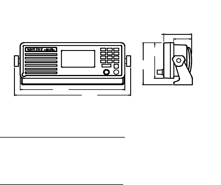
Technical Feature and Specifications .............................................3
Dimensions ............................................................................3
Electrical Specifications .......................................................... 3
Wiring Diagrams ....................................................................3
Installation ...................................................................................5
Physical Mounting ..................................................................6
Power Supply Wiring ..............................................................6
Antenna Wiring ...................................................................... 6
1.0 POWER ON/OFF .....................................................................7
2.0 Keypad Function and Display Layout ....................................7
2.1 Keypad Layout ............................................................... 7
2.2 Keypad Functions ........................................................... 8
2.3 Soft Key Function ........................................................... 9
2.4 Display Layout .............................................................. 10
3.0 Basic Operation .................................................................. 11
3.1 Key Usage .................................................................... 11
3.2 Rotary Control .............................................................. 11
4.0 Selecting A Channel ............................................................ 12
4.1 Selecting Channel List USA/Int'l/WX .............................. 12
4.2 Selecting Channel Using the Keypad ............................... 12
4.3 Selecting Channel Using the Rotary Control Knob ............. 12
4.4 Selecting a Weather Channel........................................... 12
4.5 Modify Channel Operation.............................................. 12
5.0 Volume Adjustment ............................................................ 13
6.0 Squelch Adjustment............................................................. 13
7.0 Dimmer Level ..................................................................... 14
8.0 Channel 16/9 ....................................................................... 14

ii
TABLE OF CONTENTS (con't)
9.0 Transmitting ....................................................................... 14
10.0 Dual/Triple Watch .............................................................. 15
10.1 Dual Watch .................................................................. 15
10.2 Triple Watch ................................................................ 15
11.0 Scan / Seek .......................................................................... 15
11.1 Scan ............................................................................ 15
11.2 Scan List - Add / Delete Channels ................................... 16
11.3 Scan List - View ........................................................... 16
11.4 Seek (All Scan).............................................................. 16
12.0 Transmit Power .................................................................. 16
13.0 Priority Channel ................................................................. 16
14.0 Transmitting A Distress Call ............................................... 17
15.0 Transmitting A DSC Call .................................................... 17
15.1 Individual DSC Call ...................................................... 18
15.2 Group DSC Call ............................................................ 19
15.3 Placing A Telephone Call With DSC ............................... 19
16.0 Receiving A DSC Call .......................................................... 20
17.0 Reviewing The DSC Call Log ............................................... 21
17.1 Routine DSC Calls ........................................................ 21
17.2 Distress Call Log ........................................................... 22
17.3 Missed Calls ................................................................. 23
18.0 Configuration Menu ............................................................ 23
18.1 Watch Mode Options ..................................................... 24
18.2 DSC Options ................................................................ 24
18.3 Radio Controls .............................................................. 25
18.4 Scramble Options .......................................................... 25
18.5 Channel Name .............................................................. 26
18.6 DSC Call Lists .............................................................. 26
18.7 Factory Reset ................................................................ 27
18.8 Set DSC ID .................................................................. 27

iii
TABLE OF CONTENTS (con't)
19.0 Channel Lists ...................................................................... 28
20.0 Trouble Shooting ................................................................ 33
20.1 Unlock Warning ............................................................ 33
20.2 No Audio ..................................................................... 33
21.0 Appendix A ......................................................................... 34
23.0 Appendix B ......................................................................... 35
24.0 Appendix C ......................................................................... 37
LIST OF FIGURES
1.1 Dimensions.............................................................................3
1.2 Flush Mount...........................................................................5
1.3 Mounting Bracket.................................................................... 5
1.4 Keypad...................................................................................7
1
INTRODUCTION
Congratulations on your purchase of the SEA 157S DSC/VHF marine
radio. Careful attention to design and manufacturing have gone into
making your SEA 157S one of the best marine DSC/VHF radios available
today.
This operator’s handbook is designed to show you how to get the best
performance from your radio.
Reading this handbook will give you an understanding of all the features
the SEA 157S has to offer, as well as instructions on installation,
maintenance and service.

2
SYSTEM CONSISTS OF:
Part Number: Description:
157SA/R SEA 157S VHF Radiotelephone
OPR 157S Operations manual
TEM-0157-01 Flush-mount template
FAB-0157-10 Self-adhesive-flush-mount gasket
FAB-0157-04 Trunnion bracket
KIT-0157-99 Hardware Kit:
Flush-mount hardware
Flush-mount brackets (2)
Mounting knobs (2)
Splice connector – insulated
Screw (2) – 10-32 x 5/16
Washer – neoprene (2)
Washer – nylon (2)
Plug – microphone
Fuse holder
Fuse (7.5A)
Microphone hanger
OPTIONS & ACCESSORIES:
Part Number:
MIC-0157-M9 Microphone
MIC-0002-031 Handset
SPE-0500-25 External Speaker
KIT-0157-30 Flush-mount bracket/trim ring
3
TECHNICAL FEATURES AND SPECIFICATIONS
Figure 1.1
ELECTRICAL SPECIFICATIONS
12 Vdc +30% -10% <1.0 – Amp Receive
<7.0 – Amp Transmit
WIRING DIAGRAMS Main Cable
Color Code Signal
1 - RED - 12 Vdc (+)
2 - BLACK - 12 Vdc (-)
3 - BLUE* - Audio Out
4 - ORANGE* - Internal Speaker (IN)
5 - YELLOW - (VDR) 600 Ohm Balanced
6 - GREEN - (VDR) 600 Ohm Balanced
7 - VIOLET - (VDR) Ground
8 - GRAY - AUX remote distress key
9 - BROWN - PTT
10 - WHITE/RED - Mute
11 -
WHITE - Microphone Input
12 -
SHIELD - Microphone Input GND
*NOTE: Audio Out – (BLUE) and Internal Speaker (IN) -
(ORANGE) wires must be connected in order for internal speaker
operation.
Dime
nsions:
3.6” H x 9.6” W x 2.8” D
Weight:
3 lbs (1.4 kg)
10.6 6
[270.8]
9.60
[243.8]
4.25
[108.0]
3.60
[91.3]
2.56
[64.9] 1.63
[41.5]

4
WIRING DIAGRAM Remote (SEABUSS) Cable
Color Code Signal
1 - BLACK - GND
2 - RED - 13.6V Switched
3 - VIOLET - Remote PTT
4 - GREEN - SEABUSS Data (+)
5 - BLUE - SEABUSS Data (-)
6 - YELLOW - SEABUSS Audio (+)
7 - BROWN - SEABUSS Audio (-)
8 - WHITE - ON-OFF Control
9 - SHIELD - GND
WIRING DIAGRAM Data Cable
Color Code Signal
1 - WHITE/BROWN - RS232 TxD Line
2 - BROWN/WHITE - RS232 RxD Line
3 - WHITE/ORANGE - RS232 GND
4 - WHITE/BLUE - NMEA Input (+)
5 - BLUE/WHITE - NMEA Input (-)
6 - WHITE/GREEN - NMEA Output (+)
7 - GREEN/WHITE - NMEA Output (-)
8 ORANGE/WHITE - No Connect
9 - SHIELD - GND
5
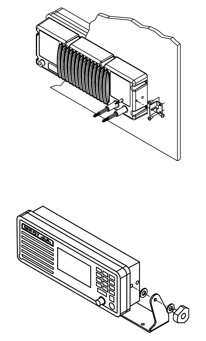
INSTALLATION
Flush Mount
Figure 1.2
Mounting Bracket
Figure 1.3

6
Physical Mounting:
Select a mounting location where the unit is easily accessed. Mount the
unit in the desired position using the provided Trunnion mount or flush
mounting kit. See Figures 1.2 and 1.3.
Power supply wiring:
CAUTION: Make sure that the provided fuse holder is installed on
the power cord between the radio and the power source, and that the
proper sized fuse (7.5A) is installed.
Use a 12 volt +30%/-10% (10.8 to 15.6VDC) DC power source for proper
operation. Do not exceed 16.0 volts. Direct connection to the battery is
recommended. Connect the heavy red wire, with in-line fuse installed, to
the positive (+) terminal and the heavy black wire to the negative (-)
terminal. Negative ground is required for the USA/Canada version of the
SEA 157S.
CAUTION: If the polarity of the power wires is reversed (Black to
positive, Red to negative), and power is accidentally applied to the radio,
the in-line fuse will blow. It is possible that damage could also occur to
some internal components. Application of voltages greater than 16.0 volts
will produce the same result. (Refer service to a qualified technician.)
Antenna wiring:
Use only the best available 50 ohm coaxial antenna cable and connectors.
The antenna must be vertically polarized. Check the antenna system for
less than 1.5:1 VSWR with an in-line wattmeter before final installation.
The antenna cable PL-259 connector should be tightly fastened to the
antenna connector on the back of the unit. All antenna connections should
be carefully protected from the weather.
7
1.0 Power On/Off
Momentarily press the PWR key to turn on the unit. The radio first
performs a diagnostic self-test, displaying any errors, then reverts to the
last channel selected.
To turn off the unit, hold the PWR key in until the display reads 'POWER
DOWN " (greater than 2 seconds), then release.
NOTE: The last volume, dim, squelch levels, and channel number are
saved when the unit is powered down using the PWR key.
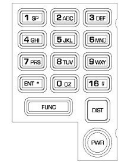
2.0 KEYPAD FUNCTION AND DISPLAY LAYOUT
2.1 Keypad Layout
Figure 1.4
Keypad
8
2.2 Keypad Functions
1/SP Alpha/Numeric Entry – Space Character
2/ABC Alpha/Numeric Entry
3/DEF Alpha/Numeric Entry
4/GHI Alpha/Numeric Entry
5/JKL Alpha/Numeric Entry
6/MNO Alpha/Numeric Entry
7/PRS Alpha/Numeric Entry
8/TUV Alpha/Numeric Entry
9/WXY Alpha/Numeric Entry
0/QZ Alpha/Numeric Entry.
ENT/* Opens and Closes Edit fields. General acknowledgement of
Prompts that require user action. On the Primary Radio
Display, this key can be used to select the radio controls:
Volume, Channel, Squelch and the Back Light level.
DIST DSC Distress Call. Press for 5 seconds to initiate a Distress
call sequence.
16/# Go to CH 16 immediately. If pressed again, switches to CH
9. Active in all radio modes.
PWR Power on/off
FUNC Generally used to access the Soft Key Menu. Also used to
navigate through Menu Levels.
NOTE: During transmit, the keypad (1-0,FUNC, ENT*, 16 #) can be used to
send DTMF tones.

9
2.3 Soft Key Functions
Pressing the FUNC key will bring up the Soft Key Menu, which will be
displayed for five seconds. Pressing one of the number keys while the
Soft Key Menu is displayed will initiate the secondary function associated
with the key, as described below.
1 – DW Starts the Dual Watch. Starts the Triple Watch if held.
2 – SCAN Starts the MEM Channel Scan.
3 – SEEK Starts the All Channel Seek.
4 – PRI Switches to the Priority Channel.
5 – LIST Displays the channels in the Memory Scan List
6 – CH GRP
Toggle between USA/INT/WX channels. Last channel
in each list is remembered
7 – 1W Toggle between 1W and 25W
8 – DSC Transmit a DSC call. User will be prompted for type
of call to transmit
9 – SQL Squelch On/Off toggle
0 – MENU Opens the primary configuration menu
1
–
DW 2
–
SCAN 3
–
SEEK
4–PRI 5–LIST 6–CH GRP
7–1W 8–DSC 9–SQL
0–MENU

10
2.4 Display Layout
The Primary Radio Display will appear as shown below:
The display may contain any of the following elements:
USA Channel list indicator
INT International list indicator
WX Weather channel list indicator
PRI Priority channel
TX Transmitting
MEM Memorized channel
1W or 25W Power indicator
SCB Scrambler On
DSC DSC mode active
SQL Squelch state on/off
A Simplex USA channel
SCN Scan is active
DW Dual Watch is active
25W USA
Distress
38* 32.123N
112* 45.041W 12:13:00
16
11
3.0 BASIC OPERATION
3.1 Key Usage
Most of the radio functions are selected using the FUNC key. The phrase
“press FUNC-6” means to press and release the FUNC key, then press
and release the 6 key. Some functions are selected by holding a number
key for longer than 1 second. The phrase “press FUNC-6 for longer than 1
second” or “hold key” means to press and release the FUNC key, then
press and hold the 6 key for longer than 1 second, then release the key.
The radio will beep, if beep is enabled, when the key is pressed. On long
key holds a double beep will be sounded when the key has been held
down long enough to enable the secondary function.
While in the Primary Radio Display, the ENT key may be used to scroll
through and select the major radio controls: Volume, Channel, Squelch
and the display Backlight level.
3.2 Rotary Control
The rotary control of the SEA 157S is used for a number of radio
functions, such as adjusting the channel, volume, squelch and
backlighting from the Primary Radio display. The rotary control is also
used to navigate through menu selection or to move the cursor position
during edit operations.
When modifying radio controls on the Primary Radio Display the rotary
control will return to the volume setting state 5 seconds* after the last
adjustment is made. During Squelch adjustment, this time is extended by
5 seconds to allow for squelch on/off time. * Rotary control timeout time
is adjustable. See Paragraph 18.3.3.
12
4.0 SELECTING A CHANNEL
4.1 Selecting Channel Lists USA/INT’L/WX
Pressing FUNC-6 will toggle the radio between the USA, INT’L and
Weather Channel Lists. The radio will go to the last used channel in the
selected list.
4.2 Selecting a Channel Using the Keypad
When the radio is in the Primary Radio Display, the numerical keys may
be used to select a channel directly. To immediately switch to a channel,
enter the two-digit channel number, including the leading zero for a single
digit channel. If a single digit is pressed, the radio will switch to that
channel following a 5 second pause.
For example, to go to channel 23 press 2,3 to switch to the channel
immediately. Press 0,5 to go to channel 5 immediately. Press 6 and pause
for 5 seconds and the radio will switch to channel 6.
4.3 Selecting a Channel Using the Rotary Control Knob
While on the Primary Radio Display, press the ENT key until “Change
Channel” is displayed, then use the rotary control to scroll through the
current channel list until the desired channel is displayed. Scrolling will
wrap around at either end of the list; for example, the display will wrap
from channel 88A to channel 1 when moving up through the list.
4.4 Selecting a Weather Channel
While in the WX channel list, press the ENT key until “Change Channel”
is displayed, then use the rotary control to scroll through the current
channel list until the desired channel is displayed. The channel number
can also be entered directly by entering it with the keypad.
4.5 Modify Channel Operation
While on the Primary Radio Display, press and hold the ENT key until
“Channel Operation” page is displayed. On this page there are several
controls available for the channel which include changing the name of the
13
channel, adding CTCSS tone option (See Paragraph x.x), make the
channel the Priority Channel and add/remove the channel from the Scan
List.
5.0 VOLUME ADJUSTMENT
The default rotary control mode is volume setting. In the Primary Radio
Display, simply turn the rotary control to adjust the volume from 0 to 15.
6.0 SQUELCH ADJUSTMENT
In the Primary Radio Display, pressing FUNC-9 will toggle the squelch
on and off, as indicated by the SQL flag in the display.
To adjust the squelch level, press ENT key until “Change SQL” is
displayed in the upper right corner of the display, then use the rotary
control to adjust the level as desired.
The radio returns to its normal operating state 5 seconds* after the last
squelch adjustment, or you may press FUNC to exit immediately.
* This time is influenced by the rotary control timeout time setting. See
Paragraph 18.3.3.
14
7.0 DIMMER LEVEL
In the Primary Radio Display, press the ENT key until “Change DIM” is
displayed in the upper right corner of the display. Use the rotary control to
adjust the display backlight to desired level, from 0 (off) to 15 (brightest).
8.0 CHANNEL 16/9
Pressing the CH16 key during most states of radio operation will return
the radio to CH16. Pressing CH 16 repeatedly will toggle the unit between
CH16 and CH9, except while transmitting.
9.0 TRANSMITTING
After selecting the desired channel, pressing the PTT switch on the
microphone will initiate transmission on that channel if it is allowed. The
TX display enunciator will light while transmitting. At the onset of PTT, a
five minute transmit timer* is started, and, if the transmission continues
longer than this period, the radio will emit four short beeps and return to
receive mode.
When transmitting on a 1W only channel, the power level may be
temporarily set to 25W if the ENT key is held while transmitting.
Pressing PTT while the radio is in other than normal receive mode, such
as volume level setting, Configuration Menu, or entering a channel
number, will cause the unit to exit the mode, return to the last selected
channel and begin transmitting immediately.
* Current FCC rules prohibit transmissions longer than five minutes in
duration.
15
10.0 DUAL/TRIPLE WATCH
10.1 Dual Watch
The SEA 157S has two watch modes available. Dual watch is initiated by
pressing FUNC-1 briefly while on the primary monitoring channel; the
Dual Watch channel will then be checked every 1.0 second for activity. If
there is activity on Dual Watch channel, the radio will hold on that
channel until there is no activity or 5** seconds. The Dual Watch channel
can be set to either CH16 or the Priority Channel in the Dual Watch setup
menu option (See Paragraph 18.1.1). The channel number display will
indicate which channel the unit is operating on. Pressing any key or PTT
will exit dual watch and switch to the current channel. The DW Flag will
be displayed when function is active.
10.2 Triple Watch
The Triple Watch function monitors three channels - CH16, the Priority
Channel and a third selected channel. To initiate the Triple Watch feature,
select a Priority Channel (Paragraph 13.0), select the third channel
(Paragraph 4.3), then press FUNC-1 for more than one second. To exit the
mode press any key or PTT.
11.0 SCAN/SEEK
The SEA 157S contains both Scan and Seek functions. Seek mode scans
all channels in the selected Channel List (USA, INT, or WX), whereas
Scan monitors channels that are members of a user-programmed Scan
List.
11.1 Scan
The Scan function is initiated by pressing FUNC-2. The radio will scan
the user-programmed list of scan channels, stopping on any active
channel, and remaining on that channel for 5** seconds after the channel
becomes inactive. The SCN Flag will be displayed when the function is
active. Pressing the “ENT” key will force the radio to temporarily skip an
active channel and continue scanning.
16
** 5 seconds is factory default. This time may be adjusted in the Radio
Controls menu (Paragraph 18.3.2).
11.2 Scan List – Add/Delete Channels
Press and hold the ENT key until the “Channel Operations” page is
displayed. If the channel is not in the scan list the bottom selection will
be “Add to Scan List”, if the current channel is in the scan list then the
bottom selection will be “Del from Scan List”.
11.3 Scan List – View
To view which channels are in the scan list press FUNC-5. Each channel
in the scan list will be display for 1 second until the end of the list.
11.4 Seek (All Scan)
Seek is started by pressing FUNC-3. The radio will scan all the channels
in the current Channel List. The SCN Flag will be displayed while the
function is active. (Paragraph 4.0)
12.0 TRANSMIT POWER
Pressing FUNC-7 toggles the transmitter power level on channels that
allow 25w transmission. On channels that only allow 1W this function has
no effect. When transmitting on a 1W only channel the “FUNC” key may
be held down while transmitting to temporarily switch to 25W. The
1W/25W display flag will indicate the current transmit power level.
13.0 PRIORITY CHANNEL
Pressing FUNC-4 switches the radio to the programmed Priority Channel.
To select the current channel as the Priority Channel, press and hold the
ENT key until the “Channel Operation” page is displayed. Use the rotary
control to move the cursor to the “Make PRI Channel” and then press the
ENT key. The Priority Channel is also used by the Triple Watch mode
and the Priority Scan and Seek modes.
17
14.0 TRANSMITTING A DISTRESS CALL
A distress DSC call may be initiated using the following procedure:
1) Press either the local DIST key or the remote DIST key. An alert tone
will sound while the key is held.
2) Select from the list of available distress conditions shown in “TYPE:”
line..
If the radio is not supplied with positioning information from a GPS or
other device, you will be prompted to enter the Lat/Long position. You
may skip this step in an emergency and go back later to enter the position.
To manually enter the position, use the keypad to input the digits and the
rotary control to move the cursor.
After selecting the distress condition and manually entering the position,
press and hold the distress key for 5 seconds to send t
he distress call.
The radio will wait for an acknowledgment from the coast station and
automatically resend the DSC message approximately every 4 minutes if a
coast station does not respond. During this time the display will show the
time until next transmission and the “WAITING FOR ACK” status. At
any time you may press the ENT key to resend the distress call
immediately.
NOTE: All DSC functions are disabled unless a valid DSC ID (MMSI number)
is programmed in the unit. See “Set DSC ID” (Paragraph21.8).
15.0 TRANSMITTING A DSC CALL
To access the DSC Calling functions, press FUNC-8. This will bring up
the primary DSC menu. The menu selections are used for reviewing
received calls, programming station IDs and transmitting the various DSC
message formats.
Most calls will conform to one of the five predefined formats which have
a simplified calling procedure: Routine Individual calls, Alternate
Channel proposal, Distress Relay calls and All Ship calls for the purpose
18
of warning. For all other calls that do not fit one of these predefined
categories, the operator may compose a call using the Build Class A
operation. Class A formats allow all call types to be generated, including
geographic area calls, group calls, non-voice (fax and data) calls, position
request and polls.
The 16 # key may be used to abort the DSC call at any point in the
process and return to the Primary Radio Display.
When a DSC call is made that does not require the receiving station to
send an acknowledgment, such as an “ALL SHIP” call, the radio switches
to the selected voice communications channel immediately after the call is
sent. When an Individual call is sent the unit will wait for an
acknowledgement to be received before switching to the selected channel.
While waiting for an acknowledgement to a DSC call the radio will
alternately display “DSC CALLING” and “WAITING FOR ACK”. The
call may be resent immediately by pressing the ENT key.
Once an acknowledgement is received the radio will switch to the selected
voice channel and the display will show “ABLE” or “UNABLE”,
depending on the response received, until the user takes action such as
keying the radio or changing channels.
15.1 INDIVIDUAL DSC CALL
A routine Individual DSC Call is used to address another station and
propose a working voice channel. This type of call requires the receiving
station to send a response.
Start by selecting the desired working channel you want to use. Press
FUNC-8 to access the DSC Menu. Using the rotary control to move the
cursor, select individual DSC Call menu item, then press ENT. The user-
programmable Individual DSC Calling list will be displayed with the last
station called selected. Use the rotary control to select the desired station.
Press ENT to initiate the DSC call.
19
15.2 GROUP DSC CALL
A routine Group Call is used to address a group of stations and propose a
working voice channel. This type of call requires no response from the
receiving stations.
Start by selecting the desired working channel you want to use. Press
FUNC-8 to access the DSC Menu. Using the rotary control to move the
cursor, select Group Call menu item, then press ENT. The user-
programmable Group Calling listwill be displayed with the last station
called selected. Use the rotary control to select the desired station. Press
ENT to initiate the DSC call.
15.3 PLACING A TELEPHONE CALL WITH DSC
The DSC call system may be used to set up a telephone call through an
appropriately equipped coast station.
To initiate a phone call, press FNC-8 to access the DSC Menu. Using the
rotary control to move the cursor, select the DSC Phone Call menu item,
then press ENT. The most recently contacted coast station’s DSC ID and
phone number will be displayed. If this information is correct, press ENT
to initiate the call.
To change the coast station’s DSC ID, use the rotary control to move the
cursor to the DSC ID field and then press ENT. Select either “Direct
Entry” or select the DSC ID from the predefined Coast Station DSC ID
list. Enter a new DSC ID if required. Press ENT to complete the entry.
To change the telephone calling number, use the rotary control to move
the cursor to the phone number field, then press ENT. Select either
“Direct Entry” or select a phone number from the predefined phone
number list. Enter the new phone number if required. Press ENT to
complete the entry.
Press the ENT key to transmit the request to the coast station. If the coast
station is able to accept the request, the radio will change to the working
channel assigned by the coast station.
20
16.0 RECEIVING A DSC CALL
The SEA 157S constantly monitors CH70 using a dedicated watch
receiver. When a DSC call is received, the radio will beep quickly 2 times
every 5 seconds. This alert tone will continue for 2 minutes or until the
user presses a keypad key or the PTT switch, at which time the alert tone
will cease. The display will indicate the type of call received, the source
of the call (either the name or DSC ID) and any other information that is
relevant to the type of call.
When a Distress Call is received the radio will sound an alternating 2-tone
distress alarm. The alert tone will continue for 2 minutes or until the user
presses a keypad key or the PTT switch, at which time the alert tone will
cease. The display will indicate that a distress call has been received.
When an All Ships or Geographic Call is received the radio will beep
once and switch to the voice channel specified by the calling station. The
display will show “ALL SHIP” or “GEO CALL” while on the selected
channel. The display will revert to its normal operating mode when the
channel selector is changed or a key is pressed.
When an Individual Call is received additional action may be taken
automatically, depending on the setting of the DSC ACK mode setup
menu.
If an automatic reply has been selected, then the acknowledgment will be
sent and the radio will switch to the voice channel selected by the calling
station.
If the manual reply mode is selected then the radio will display “ABLE”
and beep once per second. Use the "ABLE" setting, or select “UNABLE”
using the rotary control, then press the ENT key to transmit the
acknowledgment. The radio will switch to the channel selected by the
calling station if “ABLE” was sent, or remain on the current working
channel if “UNABLE” was sent.
If the Manual + Timeout Reply mode is selected then the radio will
display “UNABLE” and beep until “ABLE is selected using the rotary
control and the ENT key is pressed. If 4.5 minutes pass without the user
21
selecting “ABLE”, the radio will transmit the Unable to Comply message
and remain on current working channel.
While on the selected voice channel the display will alternate between
“INDIVID” and the name or DSC ID of the caller. The name is displayed
if the caller’s DSC ID is in the address book.
17.0 REVIEWING THE DSC CALL LOGS
17.1 ROUTINE DSC CALLS
The radio retains the last 50 received DSC calls in the DSC Log. To view
the log, press FNC-8 to access the DSC Menu. Use the rotary control to
select Review DSC Log, then press ENT. All information about the
received call, including the received time and date, will be displayed. Use
the rotary control to scroll though the log. Pressing the ENT key on a log
display will prompt you to either delete the entry or initiate a DSC Call to
the source DSC ID.
Information displayed for GEOAREA, INDIVIDUAL, GROUP, ALL
SHIPS and UNKNOWN message:
Line 1 Message number and Category
Line 2 Received from DSC ID or name
Line 3 UTC Time / Date for when the call was received
Line 4 Channel / Frequency / Position (dependent on type of call)
Line 5 ACK Status
Line 6 Telecommand 1
Line 7 Telecommand 2
Information displayed for PHONE CALL message:
Line 1 - Message number and phone number
Line 2 - Received from DSC ID or name
Line 3 - UTC Time / Date for when the call was received
Line 4 - Call Duration / Channel / Frequency / Position
Line 5 - ACK Status
Line 6 - Telecommand 1
Line 7 - Telecommand 2
Information displayed for DISTRESS CALL / RELAY or ACK message:
Line 1 - Message number and Distress Call / ACK / Relay
22
Line 2 - Received from DSC ID or name
Line 3 - UTC Time / Date for when the call was received
Line 4 - Position / Time of position fix
Line 5 - Nature of distress
Line 6 - Relay DSC ID if available
Line 7
17.2 DISTRESS CALL LOG
The radio retains the last 20 DSC Distress calls in the Distress Log. To
view the log, press FNC-8 to access the DSC Menu. Use the rotary
control to select Review Distress Log, then press ENT. All information
about the received call, including the received time and date, will be
displayed. The rotary control may be used to scroll though the log entries.
The Distress Log is organized by events, that is, all the Distress Calls sent
by or to an individual DSC ID within a 2 hour period represents a Distress
Event with the current status represented by the last call received.
If a Distress Event is active, that is, it has not been acknowledged, and the
event is more than 5 minutes from the original distress call, then the
operator may initiate a Distress Relay* or a Distress
Acknowledgement**. While viewing the Distress Event, press the ENT
key. A prompt will allow selection of a Broadcast Relay, Addressed Relay
or Acknowledgement. Select the type of call, then press the ENT key. If
an Address Call is selected, a destination DSC ID may be entered at the
subsequent prompt. All other information required for the DSC call will
be automatically inserted.
* Care should be taken when sending relay calls for another ship in
distress. A distress relay should only be sent if it has been confirmed that
the coast station did not receive the original call.
** Distress Acknowledgement should be transmitted to terminate the call
only after consulting with a Rescue Coordination Center or a Coast
Station, and being directed to do so.
The information displayed in the Distress Log contains the following
information:
Line 1 - Time / Date of original distress call
Line 2 - The DSC ID or name for the vessel in distress
23
Line 3 - Nature of the Distress
Line 4 - Position / Time of Position Fix
Line 5 - Current status (Distress, Relay, ACK)
Line 6 - The source DSC ID for the Relay or Acknowledgement
Line 7 - Time / Date of last DSC call for this event
17.3 MISSED CALLS
If a received DSC call is not acknowledged by pressing the PTT switch or
a keypad key within 5 minutes, the call is placed in the Missed Call List.
To view the Missed Call List, press FNC-8 to access the DSC Menu. Use
the rotary control to select Review Missed Calls, then press ENT. All
information about the received call, including the received time and date,
will be displayed. Use the rotary control to scroll though the log.
Pressing the ENT key will allow you to delete the entry, add to the DSC
List if not already part of that list or respond to the call. If responding,
then a DSC call will be transmitted to the received DSC ID.
Information displayed for Missed Call List:
Line 1 Message number and Category
Line 2 Received from DSC ID or name
Line 3 UTC Time / Date for when the call was received
Line 4 Channel / Frequency / Position (dependent on type of call)
Line 5 Telecommand 1
Line 6 Telecommand 2
18.0 CONFIGURATION MENU
The Configuration Menu contains general option selections and radio
functions. The Menu is entered by pressing FUNC-0. While in the
Configuration Menu, if there is no activity for 30 seconds, or if the CH16
or DIST keys are pressed, the Menu will be exited with no changes being
saved, and the radio will return to the Primary Radio Display.
The rotary control is used to scroll through the list of menu options. If a
particular configuration needs to be changed, press the ENT key to open
the edit page. Some edit pages contain more than one configurable option
24
with the cursor pointing to edit field. Use the rotary control to select the
item that needs to change and press the ENT key to begin editing. While
the option is being adjusted it will blink. Some edits use the rotary control
to select from a predefined list of configurations while others use the
keyboard to enter the data. Modify the configuration accordingly, then
press the ENT key to accept the change. While in the Configuration
Menu, pressing the FUNC key will abort an open edit. If no edit is open
the radio will back up one menu level.
18.1 Watch Mode Options
This Configuration page has the options for Channel Watch operations:
18.1.1 Dual Watch Options
Chan 16 Channel 16 has priority and is checked every 2 seconds
regardless of activity on other channels.
PRI Chan The Priority Channel has priority and is checked every 2
seconds regardless of activity on CH16 or the Primary Channel.
18.1.2 Triple Watch Options
Chan 16 Channel 16 has priority and is checked every 2 seconds
regardless of activity on the Primary or the Priority Channel.
PRI Chan The Priority Channel has priority and is checked every 2
seconds regardless of activity on CH16 or the Primary Channel.
18.2 DSC Options
This Configuration page contains options for DSC operation.
DSC ACK This option controls the radio's response to an
individual DSC call. The options include:
Auto Unable Automatic Reply, Unable to Comply The radio will
automatically send an Unable to Comply response and stay on the
current working channel.
25
Auto Able Automatic Reply, Able to Comply. The radio will send
an Able to Comply message and will switch to the channel selected
by the calling station.
Manual Time Manual + Timeout, Unable to Comply. The radio will
wait 4.5 minutes for the user to manually send an Able to Comply
message; otherwise it will send an Unable to Comply message and
stay on the current working channel.
Manual Only Manual Reply only. The radio stays on the current
working channel and waits for user to select the reply to send.
18.3 Radio Controls
This Configuration page contains a number of general radio operation
options.
18.3.1 Beep Level
Use the rotary control to select the beep volume level, 00-09.
18.3.2 Scan Hang Time
Use the rotary control to select the amount of time the radio in Scan
remains on a channel after the squelch closes, in 0.5 second increments
from 00 to 09 on the display (0 to 10 seconds).
18.3.3 Rotary Control Timeout
Use the rotary control to select the amount of time, in 0.5 second
increments, to pause after the rotary control has been used for an
alternative function before returning to the default mode selected above.
Allows selection of 0-09 (0-30 seconds).
18.4 Scramble Options
Use the rotary control to select the scrambler code, from 0 to 9, to use in
Scrambler mode. Selecting 0 turns off the Scrambler.
26
18.5 Channel Name
When this function is selected the first digit of the channel name will
begin to flash. Use the keyboard keys to enter a new character, or the
rotary control to move through the channel name. Pressing the 16 # key
will abort the editing and return to Channel 16 or Channel 9.
18.6 DSC Call Lists
Selecting this option allows selection of one of the four DSC ID lists
supported by the radio: DSC ID, Group, Phone Number and Coast
Stations. Use the rotary control to select a list to modify, then press ENT
to open the List Display.
If a list contains entries, the names will be displayed in order entered. The
rotary control may be used to scroll though the list. Press ENT to view the
complete entry. The List View page contains the following three
selections:
18.6.1 Add New
Selecting Add New will open a blank entry page where a Name and
Number may be added. The Name may be up to 15 characters long. The
DSC ID field is 9 digits. The Phone Number may be up to 18 digits.
18.6.2 Edit
Selecting Edit will allow the current entry to be modified. Use the rotary
control to move the cursor and the keyboard to enter new information.
When the edit is complete, press ENT to save the entry into the list and
return to the List Display.
18.6.3 Delete
An entry may be removed from the list with this option.
27
18.7 Factory Reset
The Factory Reset option is used to return all configuration parameters to
their factory default condition. A confirmation is required to perform the
reset. Selecting NO will abort the action and return to the Configuration
Menu.
18.8 Set DSC ID
Selecting this menu item will display the radio's current DSC ID. Press
ENT key to open the edit mode, then use the keypad keys to modify the
ID. Press ENT to save the changes. Press the FUNC key to return to the
Configuration Menu. Pressing CH16 or DIST will exit immediately
without saving any changes.

28
19.0 CHANNEL LISTS
US CHANNEL LIST
CHAN
NEL
SIMP
LEX
NUMB
ER
/DUP
LEX
TRANS
MIT
CHANNEL
DESIGNATION
01 D 156.050
01A S 156.050 Port Operations,
Commercial
02 - 156.100 RX Only
03A S 156.150
04A - 156.200 RX Only
05A S 156.250 (VTS), U.S. Only, Port
Ops
06 S 156.300 Intership Safety
07A S 156.350 Commercial
08 S 156.400 Commercial, Non-
Commercial
09 S 156.450 Commercial, Non-
Commercial
10 S 156.500 Commercial
11 S 156.550 (VTS) Commercial
12 S 156.600 (VTS) Port Ops
13 S 156.650 Bridge-to-Bridge,
Navigational
(Manual Override to 25
watts)
14 S 156.700 (VTS) Port Ops
15 S 156.750 RX Only (Coast to Ship
Environmental)
16 S 156.800 DISTRESS CALLING
17 S 156.850 Maritime Control
18A S 156.900 Commercial
19A S 156.950 Commercial
20 D 157.000 Port Ops
20A S 157.000 Port Ops, Intership
21A* S 157.050 U.S. Govt ONLY
(USCG)
22A S 157.100 U.S. Coast Guard
23 D 157.150 Public Correspondence
23A* S 157.150 U.S. Govt ONLY
24 D 157.200 Public Correspondence
25 D 157.250 Public Correspondence
26 D 157.300 Public Correspondence

29
US CHANNEL LIST
CHAN
NEL
SIMP
LEX
NUMB
ER
/DUP
LEX
TRANS
MIT
CHANNEL
DESIGNATION
27 D 157.350 Public Correspondence
28 D 157.400 Public Correspondence
60 - 156.025 RX Only
61A* S 156.075 Public Correspondence
62A - 156.125 RX Only
63A S 156.175 Port Ops, Commercial
64A S 156.225 Public Correspondence
65A S 156.275 Port Ops
66A S 156.325 U.S. ONLY, Port Ops
67 S 156.375 Commercial “Bridge-to-
Bridge” Nav
(Manual Override to 25
watts)
68 S 156.425 Non-Commercial
69 S 156.475 Non-Commercial
70 S 156.525 Digital Selective Calling
(DSC)
71 S 156.575 Non-Commercial
72 S 156.625 Non-Commercial
73 S 156.675 Port Ops
74 S 156.725 Port Ops
77 S 156.875 Port Ops, Intership Only
(Manual Override to 25
watts)
78A S 156.925 Non-Commercial
79A S 156.975 Commercial
80A S 157.025 Commercial
81A* S 157.075 U.S. Govt ONLY
82A* S 157.125 U.S. Govt ONLY
83A* S 157.175 U.S. Govt ONLY
84 D 157.225 Public Correspondence
85 D 157.275 Public Correspondence
86 D 157.325 Public Correspondence
87 D 157.375 Public Correspondence
88 D 157.425 Public Correspondence
88A S 157.425 Commercial Intership
NOTE: * Transmission subject to FCC rules.
Duplex receive frequency = ship transmit frequency +4.6 MHz

30
INT’L CHANNEL LIST
CHAN
NEL
SIMP
LEX
NUMB
ER
/DUP
LEX
TRANS
MIT
CHANNEL
DES
IGNATION
01 D 156.050 Canada Public
Correspondence
02 D 156.100 Canada Public
Correspondence
03 D 156.150
04 D 156.200
05 D 156.250
06 S 156.300 Intership
07 D 156.350
08 S 156.400 Intership
09 S 156.450
10 S 156.500
11 S 156.550
12 S 156.600
13 S 156.650
14 S 156.700
15 S 156.750
16 S 156.800 Distress and Calling
17 S 156.850
18 D 156.900
19 D 156.950
20 D 157.000
21 D 157.050
22 D 157.100
23 D 157.150 Public Correspondence
24 D 157.200 Public Correspondence
25 D 157.250 Public Correspondence
26 D 157.300 Public Correspondence
27 D 157.350 Public Correspondence
28 D 157.400 Public Correspondence
60 D 156.025 Canada Public
Correspondence
61 D 156.075
62 D 156.125
63 D 156.175
64 D 156.225

31
INT’L CHANNEL LIST
CHAN
NEL
SIMP
LEX
NUMB
ER
/DUP
LEX
TRANS
MIT
CHANNEL
DES
IGNATION
65 D 156.275
66 D 156.325
67 S 156.375
68 S 156.425
69 S 156.475
70 S 156.525 Digital Selective Calling
71 S 156.575
72 S 156.625 Intership
73 S 156.675
74 S 156.725
77 S 156.875 Intership
78 D 156.925
79 D 156.975
80 D 157.025
81 D 157.075
82 D 157.125
83 D 157.175 Public Correspondence
84 D 157.225 Public Correspondence
85 D 157.275 Public Correspondence
86 D 156.325 Public Correspondence
87 D 156.375 Public Correspondence
88 D 156.425 Public Correspondence
NOTE: * Transmission subject to FCC rules.
Duplex receive frequency = ship transmit frequency +4.6 MHz

32
WEATHER CHANNEL LIST:
CHAN
NEL
NUMB
ER
RECEIV
E
CHANNEL
DESIGNATION
WX01 162.550 - US Primary 1
WX02 162.400 - US Primary 2
WX03 162.475 - US Primary 3
WX04 163.275 -
WX05 161.650 - Canada (Channel 21B)
WX06 161.775 - Canada (Channel 83B)
WX07 162.425 - US Secondary 4
WX08 162.450 - US Secondary 5
WX09 162.500 - US Secondary 6
WX10 162.525 - US Secondary 7
NOTE: * Transmission subject to FCC rules.
Duplex receive frequency = ship transmit frequency +4.6 MHz
33
20.0 TROUBLESHOOTING
20.1 Unlock Warning
If the radio’s main receiver Phase-Locked Loop circuitry becomes
unlocked, the unit will display “UNLOCK”. The channel may be changed
in an attempt to find a channel that is locked. Transmission is disabled
while the radio is unlocked, but all other functions operate normally.
The radio may continue to receive DSC calls and Distress calls via the
Watch Receiver, but will be unable to respond until PLL lock is achieved.
If the condition persists, service by an authorized Service Center is
required to correct the problem.
20.2 No Audio
Make sure that the Audio Out (blue) and Audio In (orange) wire of the
cable are connected together.
34
21.0 APPENDIX A
NMEA Sentences
The following is a list of IEC 61162 / NMEA sentences supported by the
SEA 157S Radio. These sentences support GPS position sensors and DSC
calling functions.
Input Sentences include, but are not limited to:
GGA Global positioning system fix data
RMC Recommended minimum specific GNSS data
VTG Course over ground and ground speed
GLL Geographic position – latitude/longitude
ZDA Time and data (UTC)
RMB Recommended minimum navigation information
DSC Digital Selective Calling information
DSE Expanded Digital Selective Calling information
DSI DSC Transponder Initialize
Output Sentences include, but are not limited to:
DSC Digital Selective Calling information
DSE Expanded Digital Selective calling information
DSR DSC Transponder Response
TLL Target Latitude and Longitude coordinates
35
22.0 APPENDIX B
ITU 493 Information fields
Format Types The Format Type defines the receiving party or
addressee of the call. The available formats are:
Geographical Area Addressed to ships in a specified area.
Distress Addressed to all ships
Group Addressed to ships having a common interest
All Ships Addressed to all ships
Individual Addressed only to the specified DSC ID
Geographical Area The area for the call must be defined when
selecting Geographical Area as the Format Type. The area
may be defined using Lat/Long coordinates or as a center
point and range from the center of the area. The default
center point will be the ship’s current position, if available,
but can be set to any Lat/Lon position. The range is defined
as the number of nautical miles from the center point in all
directions.
Priority Category The Priority Category is a designator that
defines the priority of the DSC call. The categories include:
Distress In grave and imminent danger of life and property with
immediate assistance required.
Urgency Relates to safety of life or property.
Safety Important navigational or meteorological warning.
Routine Normal and routine priority.
Nature of Distress The Nature of Distress must be included in the
composition of a Distress Call. The choices include:
Fire, Explosion
Flooding
Collision
Grounding
Listing in danger of capsizing
Sinking
Disabled and adrift
Undesignated Distress
Abandoning ship
36
Piracy/Armed robbery attack
Man Overboard
EPIRB emissions
Telecommand 1 Defines the communication response format of the
receiving station following reception of a call. The
choices include:
F3E SPX FM Voice communications using simplex
F3E DPX FM Voice communications using duplex
FIB FEC FSK digital communications using automatic reception
of FEC telegraphy
FIB ARQ FSK digital communications using automatic reception
of ARQ telegraphy
UNABLE Unable to comply with request
FIB TTY FSK digital communications using automatic reception
of TTY telegraphy
IB TTYR FSK digital communications using automatic reception
of TTY telegraphy – receive only
FAX Facsimile
NO INFO No additional information
Telecommand 2
NO RESN No reason given
CONGEST The channel is congested
BUSY Coast Station or Phone number is busy
QUEUE Call is places in queue
BARRED Restricted from use
NO OP No operator present
OP UNAVL Operator is unavailable
DISABLE Equipment is disabled
RADCHAN The requested channel is
37
23.0 APPENDIX C
SEABUSS II Junction Box
The SEABUSS II Junction Box is an optional device that resides on the
SEABUSS, thereby offering additional I/O support and features not
available on the SEA 157S chassis alone. Some of the additional ports and
features include:
balanced audio line in
balanced audio line out
key line mute
remote PTT input
auxiliary output
RS-232 serial port
external microphone/speaker interface
remote control radio operation
four SEABUSS II ports
ethernet interface
When used with an external microphone and speaker, the Junction Box
may be used as a remote radio control device, performing all non-DSC
functions of an SEA 157S Remote Head.

SEA COM Corp.
7030 220th St. S.W.
Mountlake Terrace, WA 98043
USA
(425) 771-2182
FAX: (425) 771-2650
www.seacomcorp.com