SECOM TWSECOMOPC002C Access Reader User Manual 20171201 OPC001C 2C
TAIWAN SECOM CO., LTD. Access Reader 20171201 OPC001C 2C
SECOM >
User Manual

OPC001C/OPC002C User Manual
Overview:
::
:
This product is designed for the RFID card reader which is used in access control
management system. With RS485 or network communication function, a large
amount of storage space can be used to store card information, according to the
authority of the card to determine the door lock action.
Function Description:
::
:
1) Save card data and parameters in SRAM / Flash / EEPROM. Firmware updating
operation can be completed through RS232 / Ethernet communication.
2) Two-color LED indicator:
- Blue light is always on: Power status
- Blue light flashes 1 time: read the card status is normal
- Red light flash 3 times: read the card's status is abnormal
- Flashing blue and red alternately: system error (e.g. communication error and
device back cover open).
3) LCD Display:
- Chinese / English LCD Display:
- English message shows 4 row * 16 column
- Chinese message shows 4 row * 8 column
- Display Name: Company Name, Date, Card Identification Number, Operation
Status, and Work / off work Status.
4) Support MIFARE card:
- Support format ISO14443-A, ISO14443-B and so on
5) Built-in Storage Space:
-EEPROM:Used for device parameter storage
-SRAM:Used to store device parameters, card number and operation record
- Flash:Used to save the card number, operation record and firmware update
6) Keypad:
- A total of 16 keys:
10 Number keys:0 - 9
6 Function keys:F1、F2、F3、F4、Cancel key、Enter key
7) Communication Interface:
- RS-485 & Ethernet communication interface(10/100Base-T)
8) Input/Output Port:
-Input Port:Door Sensor、Exit Button、Case Sensor
-Output Port:Door Lock / Alarm or Siren
9) Date and Time Setting / Cover Open Detection / Buzzer / 3V Battery(CR2032):
- Cover Open Detection:Prevent the machine from being damaged.
- buzzer:With the use of the keypad pressing, card status, device communication
anomalies, etc.
-3V Battery(CR2032):External power is used to maintain time-clock operating
and keep data in SRAM IC. Battery continuously works for six months.
10) DIP Switch:
-PIN #1、PIN #2、PIN #3、PIN #4 :Reserve
-PIN #5;Switch On. Management card can be used to activate the access control
card machine function settings.
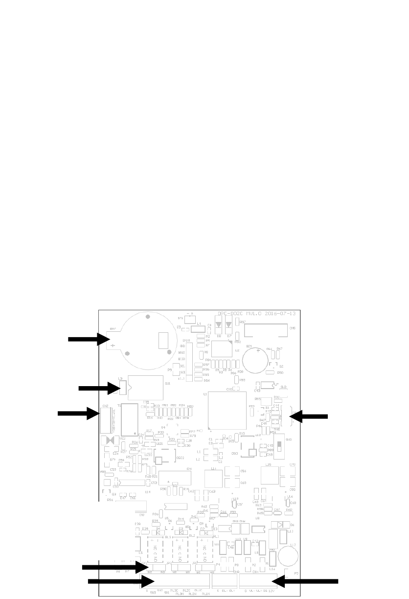
Main Board Interface Description:
::
:
Coin Battery
DIP Switch
Ethernet
I
nterface
Mini USB Interface
Setting Normally Open (NO)
or Normally Closed (NC)
Output Switch Selection
DI/DO
I
nterface
RS485 / Power Supply
I
nterface

1) RS485 / Power supply Interface (Terminal Wire)
Define PIN (5-Pin)
Name Wire
WireWire
Wire
C
CC
Color
olorolor
olor Function Description
Function DescriptionFunction Description
Function Description
1
+12 Red DC 12V INPUT
2
G Black GND
3
UL+ Blue RS485 L+
4
UL- White RS485 L-
5
G Brown RS485 GND
Define PIN (3-Pin)
2) DI/DO Interface(Terminal Wire)
Name Wire
Wire Wire
Wire C
CC
Color
olorolor
olor Function Description
Function DescriptionFunction Description
Function Description
1
RL1NO Blue DO1 RELAY NO
2
RL1C Blue DO1 RELAY COM
3
RL2NO Pink DO2 RELAY NO
4
RL2C Pink DO2 RELAY COM
5
RL3NO Green DO3 RELAY NO
6
RL3C Green DO3 RELAY COM
7
SN1 Gray
DI1 Detect the input
signal
8
SN2 Purple
DI2 Detect the input
signal
9
SN3 Brown
DI3 Detect the input
signal
10
G Black DI common ground
3)Ethernet interface (Terminal Wire)
Name Wire
Wire Wire
Wire C
CC
Color
olorolor
olor Function Description
Function DescriptionFunction Description
Function Description
1
DL+ Orange RS485 L+
2
DL- Brown RS485 L-
3
G Black RS485 GND
Name
NameName
Name
Wire
Wire Wire
Wire C
CC
Color
olorolor
olor
Function Description
Function DescriptionFunction Description
Function Description
1
RX+ Green&White Data reception +
2
RX- Green Data reception -
3
TX+ Orange&White Data transmission +
4
TX- Orange Data transmission -

OPC-001C/2C Specification
Model No. OPC-001C OPC-002C
Read Format ISO/IEC14443A/MIFARE
ISO/IEC14443A/MIFARE
ISO/IEC 14443B,
ISO/IEC 15693, JIS X 6319-4
(comparable with FeliCa)
Cardholders 16,000 (max) 20,000 (max)
Read Range 3-5 (max )
Input Ports 3 Sensors
Output Port Relay x 3
LED Indicator Power / Comm.
LCD Display 128 x 64 Dot. Graphic Display with backlight
Keypad 16 Key (F1-F4, 0-9, Cancel, Enter)
Real Time Clock Yes
Beep Tone Buzzer
Tamper switch Yes
Power Input DC 12V / 1A
Current Consumption
250mA(max)
Comm. Interface RS-485 / TCP/IP
Comm. Baudrate RS-485:9,600/19,200 bps-N-8-1, TCP/IP:10/100 Mbps
Operating Temp. 0° C ~ 55° C / 32° F ~ 131° F
Relative Humidity 20% ~ 90%
Dimension 150mm(L),100mm(W),30mm(H)
Weight 260g
Shell material ABS

Cautions to the user
The changes or modifications not expressly approved by the party responsible for compliance could void the user’s
authority to operate the equipment.
This Device complies with Part 15 of the FCC rules. Operation is subject to the following two conditions:
(1) This Device may not cause harmful interference
(2) This Device must accept any interference received, including interference that may cause undesired operation.
Note:
This equipment has been tested and found to comply with the limits for a Class B digital device, pursuant to part 15 of
the FCC Rules. These limits are designed to provide reasonable protection against harmful interference in a
residential installation. This equipment generates, uses and can radiate radio frequency energy and, if not installed
and used in accordance with the instructions, may cause harmful interference to radio communications. However,
there is no guaranty that interference will not occur in a particular installation. If this equipment does cause harmful
interference to radio or television reception, which can be determined by turning the equipment off and on, the user is
encouraged to try to correct the interference by one or more of the following measures:
● Reorient or relocate the receiving antenna.
● Increase the separation between the equipment and receiver.
● Connect the equipment into an outlet on a circuit different from that to which the receiver is
connected.
● Consult the dealer or an experienced radio / TV technician for help.