SEDO DF-5000 Digital Video Recorder Card User Manual
SEDO Co., Ltd. Digital Video Recorder Card
UserManual.wiki
>
SEDO
>
DF 5000 User Manual
User Manual
Navigation menu
Upload a User Manual
Namespaces
Wiki Guide
HTML
PDF
Info
Views
User Manual
Discussion / Help
Navigation

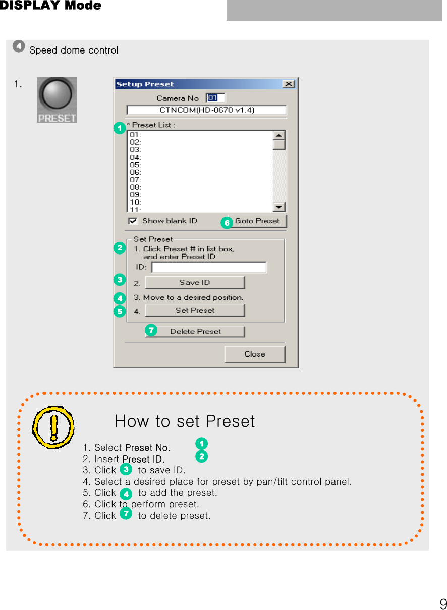
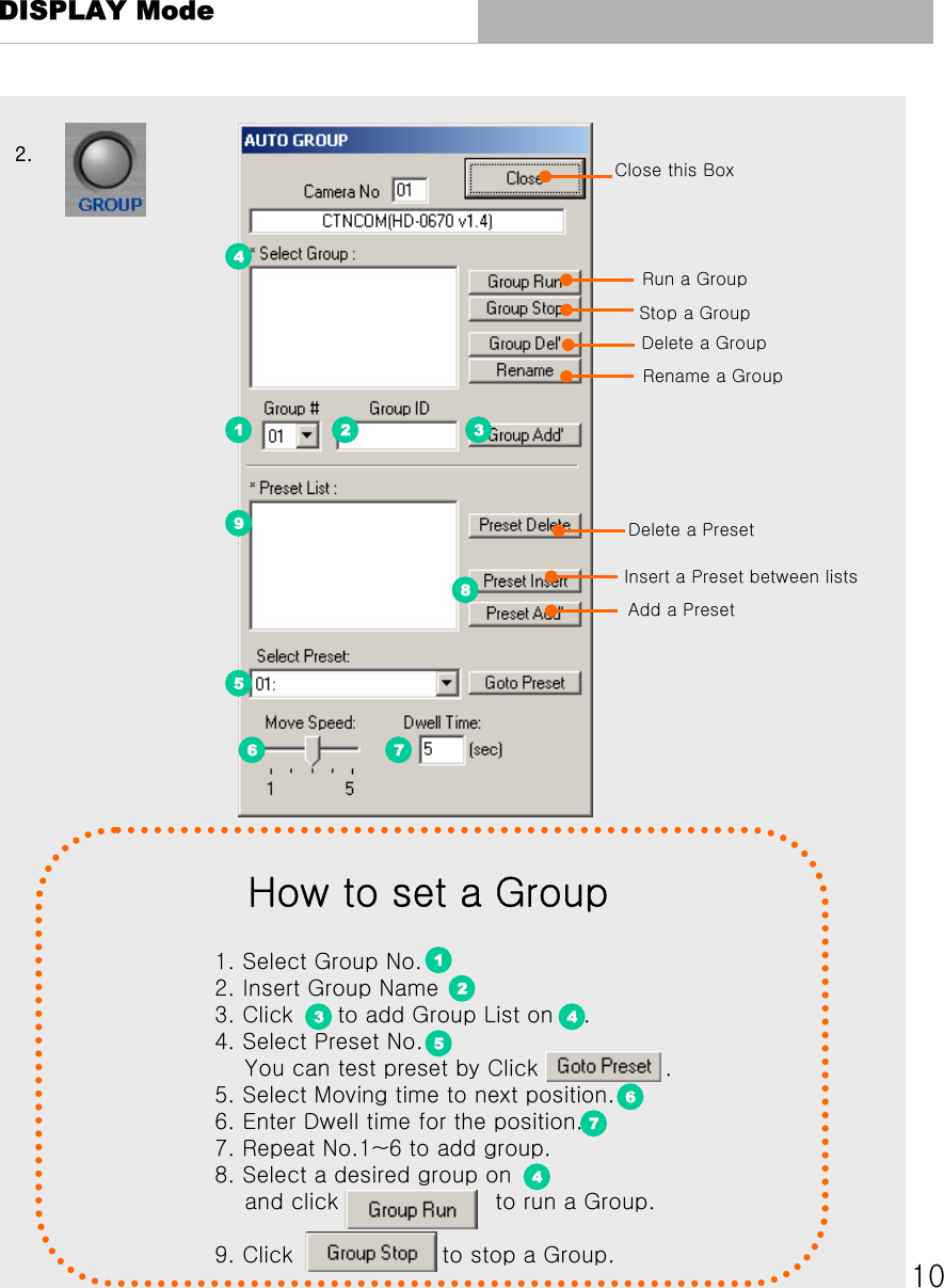

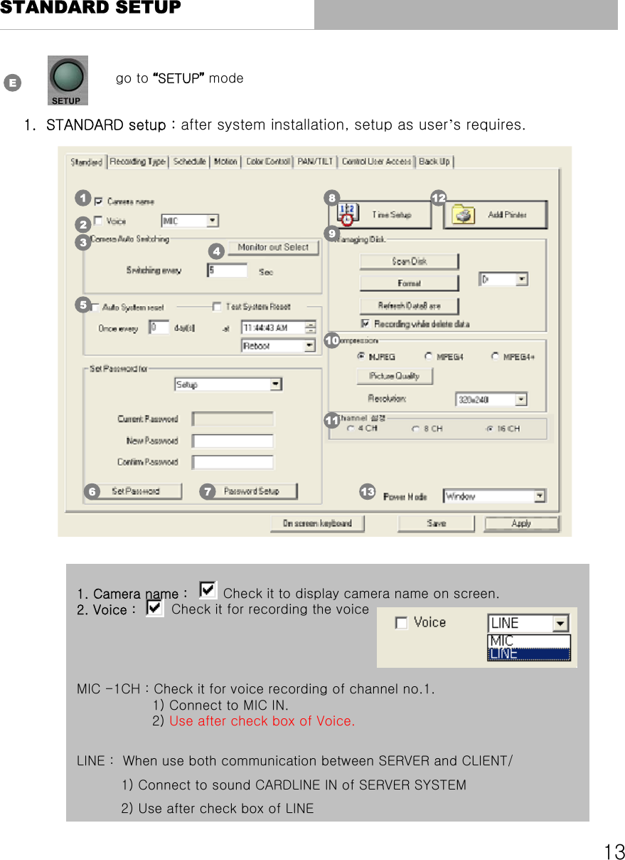
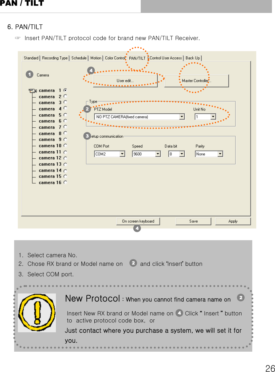
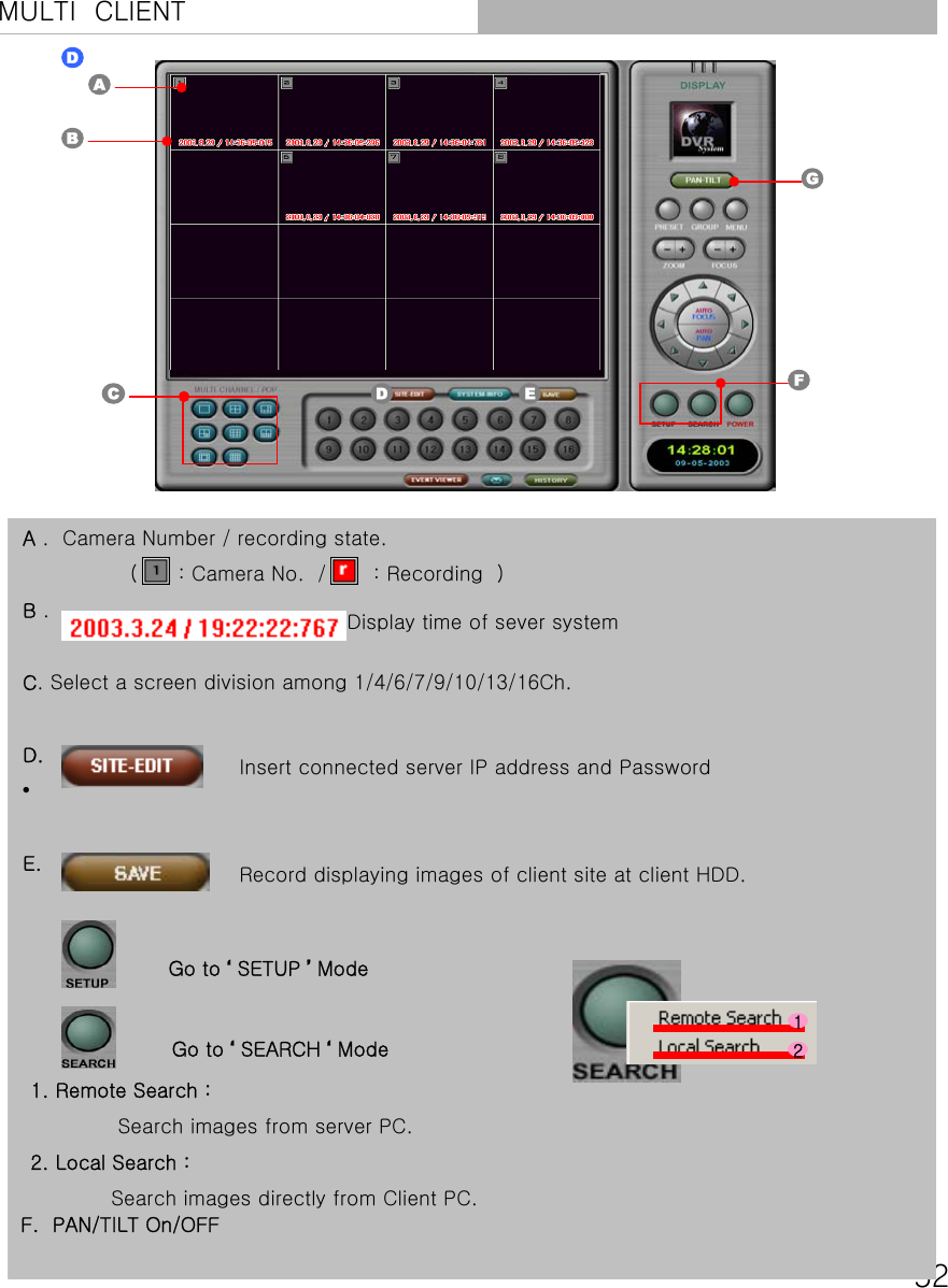
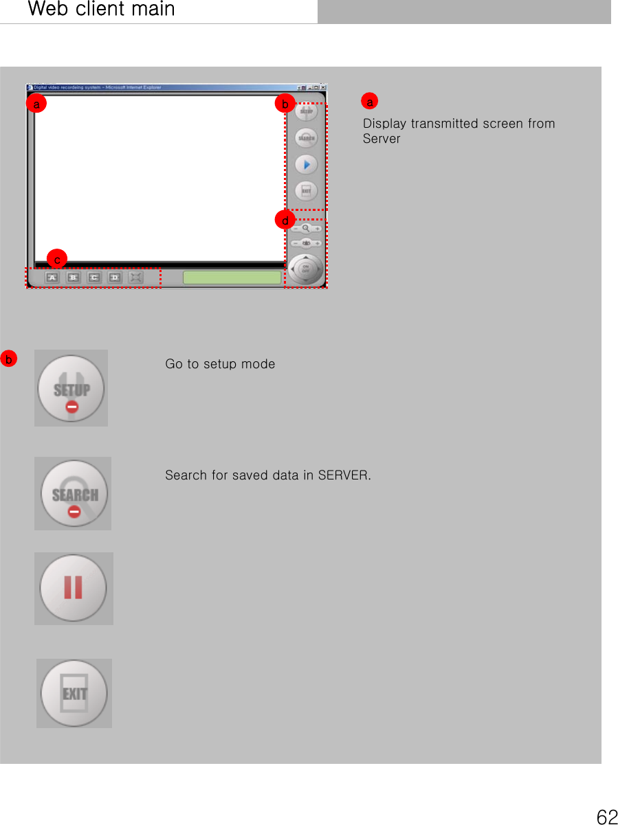
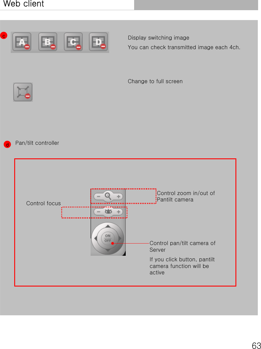
![271) Special feature- User can select different unit# each screen without concern for camera#- User can select baudrate, databits, parity- Therefore, DVR has a flexibility for PTZ camera setup and it will be possible to connect multi pantilt1. Unit# & Communication condition 2) How to use :- In SETUP screenClick [Port setup] button -> Select baudrate, datebits, parity and unit#. 3) Notice:- When user selected same PTZ camera & unit# in different camera#, if user operates one of them, both of them works.2. Select "NO PTZ CAMERA“- Patilt function button will be not active.](https://usermanual.wiki/SEDO/DF-5000/User-Guide-376175-Page-28.png)