SEGI GT1000 Modem User Manual
SEGI LIMITED Modem
UserManual.wiki
>
SEGI
>
GT1000 User Manual
User manual
Navigation menu
Upload a User Manual
Namespaces
Wiki Guide
HTML
PDF
Info
Views
User Manual
Discussion / Help
Navigation
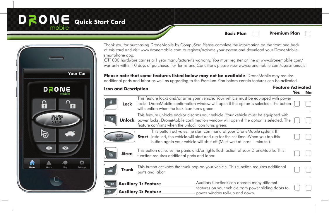
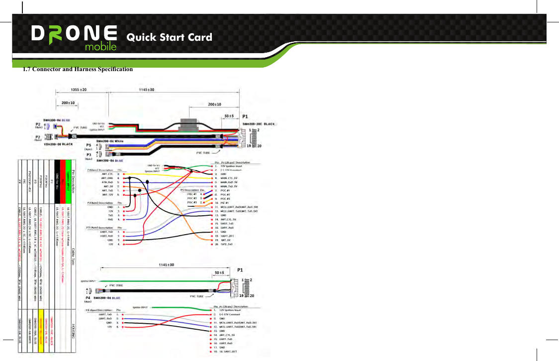

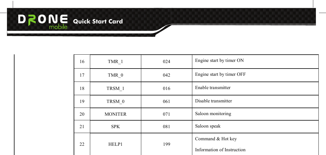
![Quick Start Card Category No Alphanumeric [PASSWORD+] Numeric [PASSWORD+] Description 1 ARM 001 Arm/Lock/Start alarm 2 DISARM 002 Disarm/Unlock/Stop alarm 3 STATUS 004 System status checking 4 PANIC 101 Panic/Jack Stop mode on 5 START 102 Remote Start of engine 6 STOP 120 Remote Stop of engine 7 TRUNK 103 Open trunk 8 CHN1_1 104 Additional channel 1 ON 9 CHN2_1 023 Additional channel 2 ON 10 VALET_1 013 VALET mode ON 11 VALET_0 031 VALET mode OFF 12 SNS_1 014 Shock sensor ON 13 SNS_0 041 Shock sensor OFF 14 TILTS_1 015 Tilt sensor ON (TAIGA system only) 1.Instruction 15 TILTS_0 051 Tilt sensor OFF (TAIGA system only)](https://usermanual.wiki/SEGI/GT1000/User-Guide-1502302-Page-14.png)
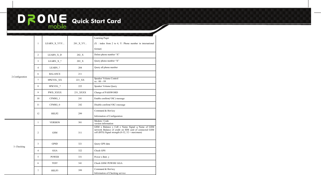
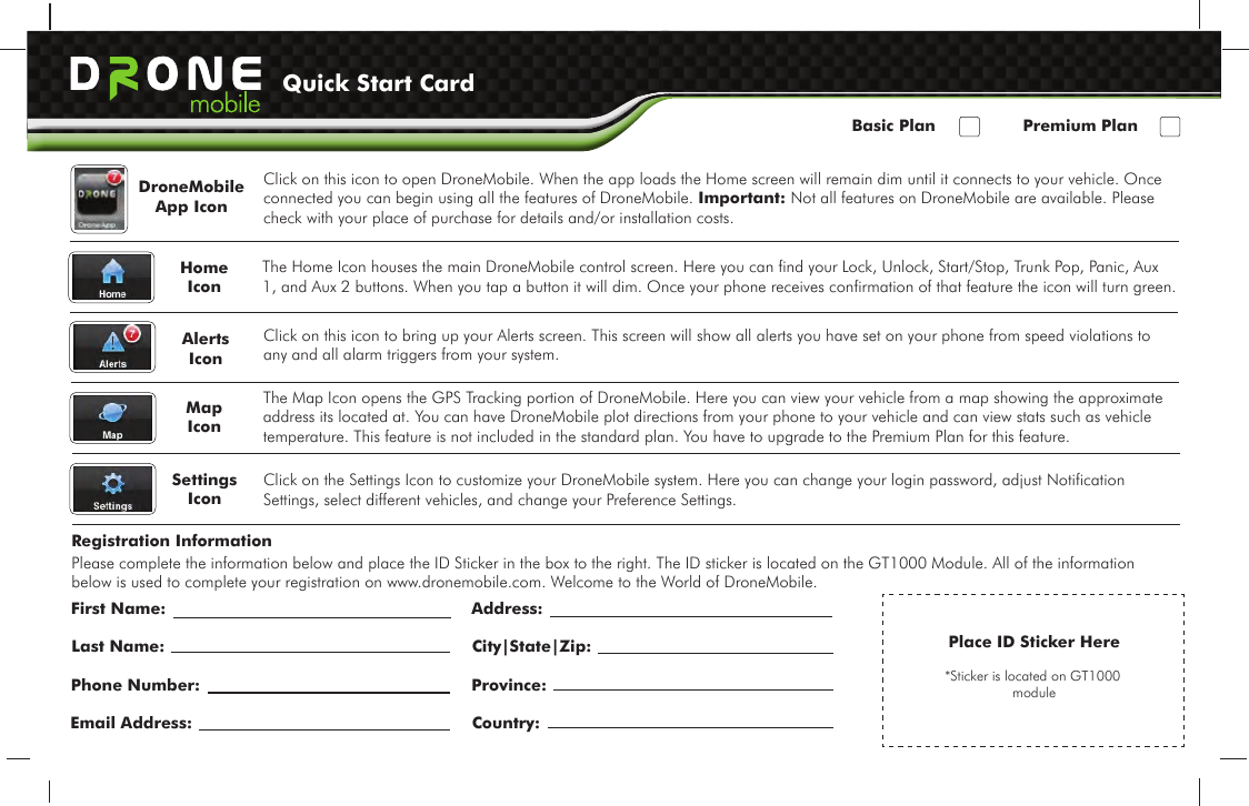
![Quick Start Card version information 2 GSM 311 GSM x Balance y Cell z Name Signal q Name of GSM network Balance of credit on SIM card of connected GSM cell (BTS) Signal strength (0-32, 32 = maximum) 3 GPSD 321 Query GPS data 4 GGA 322 Check GPS 5 POWER 331 Power x Batt. y 6 TEST 341 Check GSM/ POWER/ GGA 3. Checking 7 HELP3 399 Command & Hot key Information of Checking service 4.4 SMS Alarm and response message table Category NO SMS Instruction Numeric [PASSWORD+] Description 1 ALARM BY IGNITION 401 Alarm by Ignition Trigger 2 ALARM BY DOORS 402 Alarm by Door Trigger 3 ALARM BY TRUNK 403 Alarm by Trunk Trigger 4 ALARM BY HOOD 404 Alarm by Hood Trigger 5 ALARM BY SHOCK SENSOR 405 Alarm by Shock Sensor 6 PREALARM BY SHOCK SENSOR 406 Prealarm by Shock Sensor 7 ALARM BY TILT SENSOR 407 Alarm by Tilt Sensor (TAIGA system only) 8 CAR BATTERY REMOVED 408 Battery of Vehicle was removed 9 CAR CALL 409 Car Call 10 PAGER BATTERY LOW LEVEL 410 Battery level of Pager is low 11 ALARM BY EMERGENCY CALL 411 Alarm by emergency call 1. Alarm 12 BALANCE LOW 412 Low prepaid credit 1 OK N/A Successfully Command or Hot key was executed 2. Response 2 FAIL (Error Reason) N/A Command or Hot key was not executed After alarm is triggered user can stop alarm by using ‘Arm/Disarm’ SMS command or just phone call to GT1000 unit by using authorized phone.](https://usermanual.wiki/SEGI/GT1000/User-Guide-1502302-Page-17.png)