User manual
Thank you for purchasing DroneMobile by CompuStar. Please complete the information on the front and back
of this card and visit www.dronemobile.com to register/activate your system and download your DroneMobile
smartphone app.
GT1000 hardware carries a 1 year manufacturer’s warranty. You must register online at www.dronemobile.com/
warranty within 10 days of purchase. For Terms and Conditions please view www.dronemobile.com/usersmanuals
Please note that some features listed below may not be available. DroneMobile may require
additional parts and labor as well as upgrading to the Premium Plan before certain features can be activated.
Feature Activated
Yes No
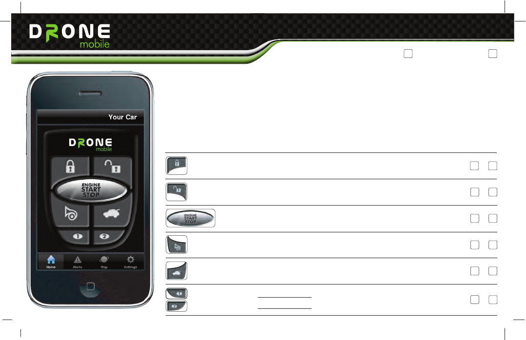
Lock
Unlock
Start
Siren
Trunk
Auxiliary 1: Feature
Auxiliary 2: Feature
This feature locks and/or arms your vehicle. Your vehicle must be equipped with power
locks. DroneMobile confirmation window will open if the option is selected. The button
will confirm when the lock icon turns green.
This feature unlocks and/or disarms your vehicle. Your vehicle must be equipped with
power locks. DroneMobile confirmation window will open if the option is selected. The
feature confirms when the unlock icon turns green.
This button activates the start command of your DroneMobile system. If
installed, the vehicle will start and run for the set time. When you tap this
button again your vehicle will shut off (Must wait at least 1 minute ).
This button activates the panic and/or lights flash action of your DroneMobile. This
function requires additional parts and labor.
This button activates the trunk pop on your vehicle. This function requires additional
parts and labor.
Auxiliary functions can operate many different
features on your vehicle from power sliding doors to
power window roll-up and down.
Icon and Description
Quick Start Card
Basic Plan Premium Plan
Quick Start Card
Registration Information
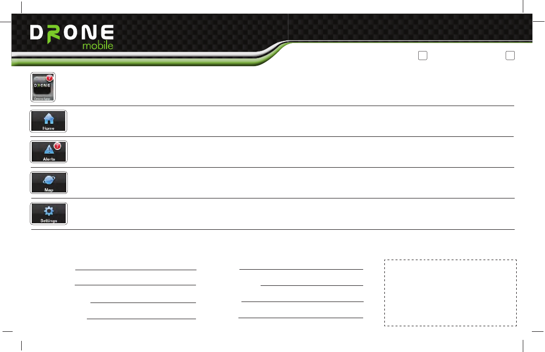
DroneMobile
App Icon
Home
Icon
Alerts
Icon
Map
Icon
Settings
Icon
First Name:
Last Name:
Phone Number:
Email Address:
Please complete the information below and place the ID Sticker in the box to the right. The ID sticker is located on the GT1000 Module. All of the information
below is used to complete your registration on www.dronemobile.com. Welcome to the World of DroneMobile.
Address:
City|State|Zip:
Province:
Country:
Place ID Sticker Here
*Sticker is located on GT1000
module
Click on this icon to open DroneMobile. When the app loads the Home screen will remain dim until it connects to your vehicle. Once
connected you can begin using all the features of DroneMobile. Important: Not all features on DroneMobile are available. Please
check with your place of purchase for details and/or installation costs.
The Home Icon houses the main DroneMobile control screen. Here you can find your Lock, Unlock, Start/Stop, Trunk Pop, Panic, Aux
1, and Aux 2 buttons. When you tap a button it will dim. Once your phone receives confirmation of that feature the icon will turn green.
Click on this icon to bring up your Alerts screen. This screen will show all alerts you have set on your phone from speed violations to
any and all alarm triggers from your system.
The Map Icon opens the GPS Tracking portion of DroneMobile. Here you can view your vehicle from a map showing the approximate
address its located at. You can have DroneMobile plot directions from your phone to your vehicle and can view stats such as vehicle
temperature. This feature is not included in the standard plan. You have to upgrade to the Premium Plan for this feature.
Click on the Settings Icon to customize your DroneMobile system. Here you can change your login password, adjust Notification
Settings, select different vehicles, and change your Preference Settings.
Basic Plan Premium Plan
Quick Start Card
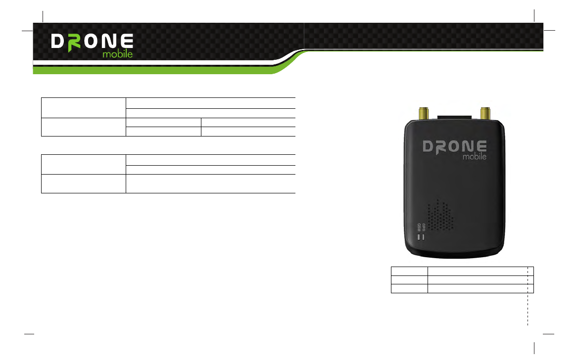
SEGI R&D
GT1000 Operation Manual
1.3 Electrical
+12 ~ +24V
Operating Voltage
Active < 50 mA (avg) @ 12V
Power Consumption
Power save < 20 mA (avg) @ 12V
1.4 Environment
Operating : -20°C ~ +60°C
Temperature
Storage : -45°C ~ +85°C
Humidity 0 ~ 95RH @ 40C
1.5 Outlook
Size 98.4mm x 66.1mm x 20.5mm
Weight 78.9g
Color Black
Quick Start Card
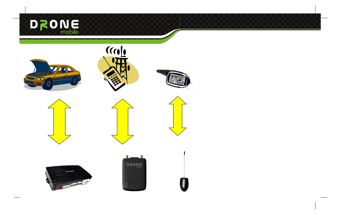
Wired connect
FM Radio
GSM/GPRS/GPS
Quick Start Card
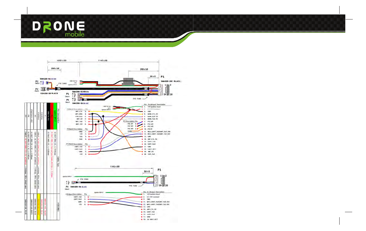
1.7 Connector and Harness Specification
Quick Start Card
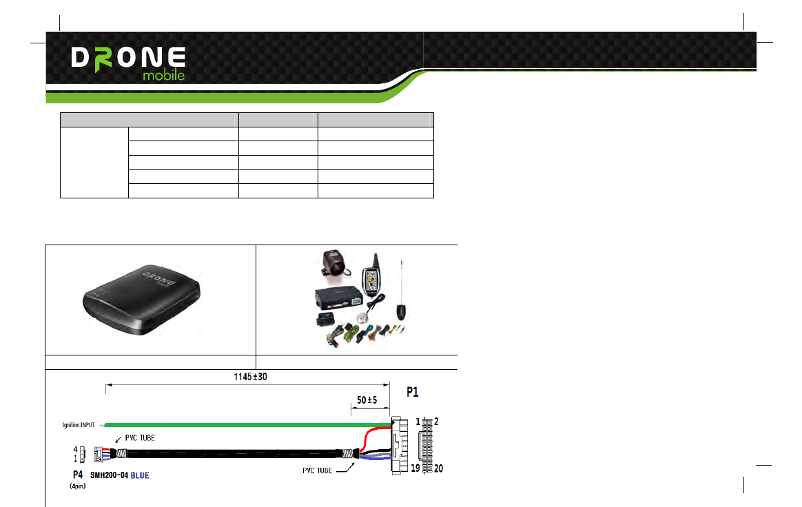
2. Package & Accessory(TBD)
Item Description Remark
Main set(GT1000) 1EA
Harness Cable SEGI OEM
User Manual Soft cover
Quick Guide 1page
Default
Gift Box 1box
2.1 Basic
GT1000 Main package
Quick Start Card
3.2 GSM/GPRS Status LED operation
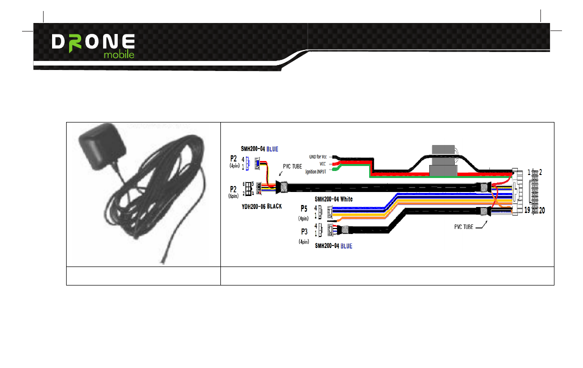
2.2 Optional Accessory
External GPS Antenna + Pad Optional harness
Quick Start Card
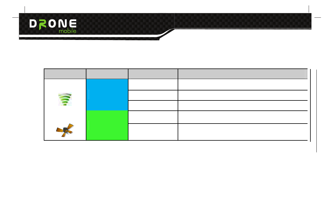
3. LED Indicator
3.1 Description
Item Color Status Description
Solid Traffic state
Blinking Idle state
GSM/GPRS
Blue
OFF 3 Times flashing
Blinking Good GPS signal
GPS
Green
ON Bad GPS signal
Quick Start Card
3.2 GSM/GPRS Status LED operation

Quick Start Card
4. SMS Interface ( Exclude USA)
4.1 Programming GT1000 unit and Transmitters.
The main controller system can memorize one GT1000 unit and two transmitters. In order to install GT1000 unit and
transmitters, following process is needed.
Note. In order to install GT1000 unit to vehicle, the magicar 7 or upper system is needed.
Note. The magicar 7 or upper system user does not need firmware update to install GT1000 unit.
1) In the system is ‘disarm’ and ignition ’ON’ condition, press the button of the RPS sensor for 2 seconds.
The system will flash light once.
2) Within 5 seconds, press the button of the RPS sensor. The system will flash light twice.
3) After 5 seconds, the LED of the RPS sensor will turn on.
4) Within 5 seconds, press the button 1 of first transmitter for 0.5 second. If the first transmitter is installed successfully,
the system will flash light once.
5) Within 5 seconds, press the button 1 of second transmitter for 0.5 second. ( If there is no second transmitter
to program, please press again the button 1 of first transmitter for 0.5 second.) If the second transmitter is
successfully installed, the system will flash light once.
6) Just wait for 5seconds, then the system will flash light twice and the system exits from the remotes
program mode.

Quick Start Card
4.2 SMS Instruction table
The GT1000 unit can be configured, controlled and values can be read from it remotely using the SMS
messages. SMS message in the following form has to be sent to the phone number of SIM card inserted in the
unit:
XXXXCommand P
Parameter value ex) 0, 1, ?....
Space ( In the following description the “_” means space )
Key word of the command or name of input,
output, or set in configuration
4 digits of Password set in configuration
· The default value of Password in GT1000 from production, or after initialization by INIT command is set to 1234 (Note. the password in GT1000 and
PIN on the SIM card are not the same number)
· There is no difference between small and capital letters used in the command
· Parameter values are for example: 0= switch off; 1= switch on; ?= ask setting;
· A reply or a confirmation of a command performance will be sent back to the number that the command came from, the reply will include the
command used and relevant parameter value
· If a phone number is used as a parameter, it is recommended to enter such number in
international format such as +71234567890

Quick Start Card
4.3 Examples:
Send the following text in a SMS message to the phone number of the SIM card inserted in the GT1000 unit
that has Password set in configuration to 1234:
1234PWD_4321 (or 1234205_4321)
sets password to 4321
1234BALANCE (or 1234202)
returns a message to the mobile phone with value of prepaid credit at the SIM card, if it is possible to find out
1234GPSD (or 1234303)
returns SMS message with text containing the current GPS geographical coordinates, if available
1234Arm (or 1234001)
activate arm with lock
1234Start (or 1234102)
activate remote start
1234SNS_0 (or 1234041_0)
shock sensor off
1234Learn_2_+71234567890 (or 1234201_2_+71234567890)
sets phone number memory #2 +71234567890
Quick Start Card
Category No Alphanumeric
[PASSWORD+]
Numeric
[PASSWORD+] Description
1 ARM 001 Arm/Lock/Start alarm
2 DISARM 002 Disarm/Unlock/Stop alarm
3 STATUS 004 System status checking
4 PANIC 101 Panic/Jack Stop mode on
5 START 102 Remote Start of engine
6 STOP 120 Remote Stop of engine
7 TRUNK 103 Open trunk
8 CHN1_1 104 Additional channel 1 ON
9 CHN2_1 023 Additional channel 2 ON
10 VALET_1 013 VALET mode ON
11 VALET_0 031 VALET mode OFF
12 SNS_1 014 Shock sensor ON
13 SNS_0 041 Shock sensor OFF
14 TILTS_1 015 Tilt sensor ON (TAIGA system only)
1.Instruction
15 TILTS_0 051 Tilt sensor OFF (TAIGA system only)
Quick Start Card
version information
2 GSM 311
GSM x Balance y Cell z Name Signal q Name of GSM
network Balance of credit on SIM card of connected GSM
cell (BTS) Signal strength (0-32, 32 = maximum)
3 GPSD 321 Query GPS data
4 GGA 322 Check GPS
5 POWER 331 Power x Batt. y
6 TEST 341 Check GSM/ POWER/ GGA
3. Checking
7 HELP3 399 Command & Hot key
Information of Checking service
16 TMR_1 024 Engine start by timer ON
17 TMR_0 042 Engine start by timer OFF
18 TRSM_1 016 Enable transmitter
19 TRSM_0 061 Disable transmitter
20 MONITER 071 Saloon monitoring
21 SPK 081 Saloon speak
22 HELP1 199
Command & Hot key
Information of Instruction
Quick Start Card
version information
2 GSM 311
GSM x Balance y Cell z Name Signal q Name of GSM
network Balance of credit on SIM card of connected GSM
cell (BTS) Signal strength (0-32, 32 = maximum)
3 GPSD 321 Query GPS data
4 GGA 322 Check GPS
5 POWER 331 Power x Batt. y
6 TEST 341 Check GSM/ POWER/ GGA
3. Checking
7 HELP3 399 Command & Hot key
Information of Checking service
1 LEARN_X_YYY... 201_X_YY...
Learning Pager
(X : index from 2 to 4, Y: Phone number in international
format)
2 LEARN_X_D 202_X Delete phone number “X”
3 LEARN_X_? 203_X Query phone number “X”
4 LEARN_? 204 Query all phone number
6 BALANCE 211
7 SPKVOL_XX 221_XX Speaker Volume Control
xx : 00 ~ 99
8 SPKVOL_? 222 Speaker Volume Query
9 PWD_XXXX 231_XXXX Change of PASSWORD
10 CFMSG_1 241 Enable confirm(‘OK’) message
11 CFMSG_0 242 Disable confirm(‘OK’) message
2.Configuration
12 HELP2 299
Command & Hot key
Information of Configuration
1 VERSION 301 Modem / Code
version information
2 GSM 311
GSM x Balance y Cell z Name Signal q Name of GSM
network Balance of credit on SIM card of connected GSM
cell (BTS) Signal strength (0-32, 32 = maximum)
3 GPSD 321 Query GPS data
4 GGA 322 Check GPS
5 POWER 331 Power x Batt. y
6 TEST 341 Check GSM/ POWER/ GGA
3. Checking
7 HELP3 399 Command & Hot key
Information of Checking service
Quick Start Card
version information
2 GSM 311
GSM x Balance y Cell z Name Signal q Name of GSM
network Balance of credit on SIM card of connected GSM
cell (BTS) Signal strength (0-32, 32 = maximum)
3 GPSD 321 Query GPS data
4 GGA 322 Check GPS
5 POWER 331 Power x Batt. y
6 TEST 341 Check GSM/ POWER/ GGA
3. Checking
7 HELP3 399 Command & Hot key
Information of Checking service
4.4 SMS Alarm and response message table
Category NO SMS Instruction Numeric
[PASSWORD+] Description
1 ALARM BY IGNITION 401 Alarm by Ignition Trigger
2 ALARM BY DOORS 402 Alarm by Door Trigger
3 ALARM BY TRUNK 403 Alarm by Trunk Trigger
4 ALARM BY HOOD 404 Alarm by Hood Trigger
5 ALARM BY SHOCK SENSOR 405 Alarm by Shock Sensor
6 PREALARM BY SHOCK SENSOR 406 Prealarm by Shock Sensor
7 ALARM BY TILT SENSOR 407 Alarm by Tilt Sensor (TAIGA system only)
8 CAR BATTERY REMOVED 408 Battery of Vehicle was removed
9 CAR CALL 409 Car Call
10 PAGER BATTERY LOW LEVEL 410 Battery level of Pager is low
11 ALARM BY EMERGENCY CALL 411 Alarm by emergency call
1. Alarm
12 BALANCE LOW 412 Low prepaid credit
1 OK N/A Successfully Command or Hot key was executed
2. Response
2 FAIL (Error Reason) N/A Command or Hot key was not executed
After alarm is triggered user can stop alarm by using ‘Arm/Disarm’ SMS command or just phone call to GT1000
unit by using authorized phone.
Quick Start Card
version information
2 GSM 311
GSM x Balance y Cell z Name Signal q Name of GSM
network Balance of credit on SIM card of connected GSM
cell (BTS) Signal strength (0-32, 32 = maximum)
3 GPSD 321 Query GPS data
4 GGA 322 Check GPS
5 POWER 331 Power x Batt. y
6 TEST 341 Check GSM/ POWER/ GGA
3. Checking
7 HELP3 399 Command & Hot key
Information of Checking service
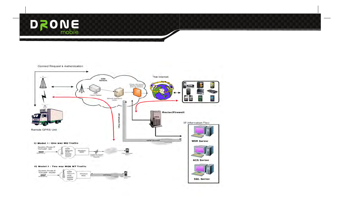
5. DATA Interface
The device always connect data network for immediate connection.
5.1 Controls

Quick Start Card
version information
2 GSM 311
GSM x Balance y Cell z Name Signal q Name of GSM
network Balance of credit on SIM card of connected GSM
cell (BTS) Signal strength (0-32, 32 = maximum)
3 GPSD 321 Query GPS data
4 GGA 322 Check GPS
5 POWER 331 Power x Batt. y
6 TEST 341 Check GSM/ POWER/ GGA
3. Checking
7 HELP3 399 Command & Hot key
Information of Checking service
5.1 Controls
Get Location, Live track, Remote start, lock, unlock, siren, trunk release, Aux1, Aux2, History Log
5.2 Alert
Displays alerts that are originated from GT1000
a) Alarm Alerts : hood, door, trunk, shock II, Analog Alarm In
b) Regular Alerts : RPS, Shock I, speed violation, Curfew violation, POI Alert, Geo-fence alert,
Ignition on/off
5.3 Settings
a) Notification Setting : Alarm/regular alerts, low battery, Engine on/off, Maintenance reminder, speed
violations, Curfew violations, POI Violations, Geo-fence violation
b) Controller Settings : Siren, shock, turbo timer, passive arming, valet mode, drive lock
c) Maintenance reminder : Mileage

Quick Start Card
version information
2 GSM 311
GSM x Balance y Cell z Name Signal q Name of GSM
network Balance of credit on SIM card of connected GSM
cell (BTS) Signal strength (0-32, 32 = maximum)
3 GPSD 321 Query GPS data
4 GGA 322 Check GPS
5 POWER 331 Power x Batt. y
6 TEST 341 Check GSM/ POWER/ GGA
3. Checking
7 HELP3 399 Command & Hot key
Information of Checking service
6. Type Approval
6.1 PTCRB Certification
■ PTCRB certification testing
■ Pre-conformance and conformance testing (RF, RRM and Protocols)
■ Regulatory testing (RF, EMC & Safety)
■ SAR, OTA & RF performance testing
■ Interoperability testing
■ Performance testing
■ Field Trials, SIM, SATK, A-GPS, MMS, Supplementary services, etc.
■ Network operators acceptance testing

This device complies with part 15 of the FCC Rules.
Operation is subject to the following two conditions:
(1) This device may notcause harmful interference, and
(2) this device must accept any interference received,
including interference that may cause undesired operation.
IC Warning This device complies with Industry Canada licence-exempt RSS standard(s).
Operation is subject to the following two conditions:
(1) this device may not cause interference, and
(2) this device must accept any interference, including interference that may cause
undesired operation of the device.
Le présent appareil est conforme aux CNR d'Industrie Canada applicables aux appareils
radio
exempts de licence.L'exploitation est autorisée aux deux conditions suivantes :
(1) l'appareil ne doit pas produire de brouillage, et
(2) l'utilisateur de l'appareil doit accepter tout brouillage radioélectrique subi,
même si le brouillage est susceptible d'en compromettre le fonctionnement.
This equipment complies with FCC radiation exposure limits set forth for an uncontrolled
environment.
This equipment should be installed and operated with minimum 20 cm
between the radiator and your body.
Caution: Any changes or modi fications to this device not explicitly approved by
manufacturer could void your authority to operate this equipment.
This equipment has been tested and found to comply with the limits for a Class B digital
device,
pursuant to Part 15 of the FCC Rules. These limits aredesigned to
provide reasonable protection against harmful interference in aresidential installation.
This equipment generates, uses and can radiate radiofrequency energy and,
if not installed and used in accordance with the instructions,
may cause harmful interference to radio communications. However,
there is no guarantee that interference will not occur in a particular installation.
If this equipment does cause harmful interference to radio or television reception,
which can be determined by turning the equipment off and on,
the user isencouraged to try to correct the interference by one or more of the following
• Reorient or relocate the receiving antenna.
• Increase the separation between the equipment and receiver
• Connect the equipment into an outlet on a circuit different from that to which the
receiver is connected.
• Consult the dealer or an experienced radio/TV technician for help.