SEIKAKU TECHNICAL GROUP DMT-300LV Wireless Microphone Transmitter User Manual
SEIKAKU TECHNICAL GROUP LIMITED Wireless Microphone Transmitter
User Manual
WIRELESS MICROPHONE
SYSTEM
DMT-300LV
INSTRUCTION
MANUAL
NF01912-1.0
SEIKAKU TECHNICAL GROUP LIMITED
UNIT 1107 BLK.A2,YAU TONG INDUSTRIAL CITY .NO.17,KO FAI ROAD,KOWLOON,HONG KONG.
http://www.dmtmic.com Tel: 886-4-22313737
email: alto@altoproaudio.com Fax: 886-4-22346757
All rights reserved to DMT. All features and content might be changed
without prior notice. Any photocopy, translation, or reproduction of part of this
manual without written permission is forbidden.
Copyright 2004 SEKAKU ELECTRON INDUSTRY (H.K.) CO., LTD.
c
RR
RR
22
NO.
1
2
3
5
4
7
6
9
8Frequency Response
Current
Carrier Frequency Range
RF Radiation
Total Harmonic Distortion
Oscillation Mode
Modulation Mode
Frequency Stability
Spurious Emission
ELECTRIC PARAMETER
75mA
50Hz-15KHz 3dBm
VHF Band 174~216MHz
FM(F3E)
10mW
45dBm
0.005%/25
Quartz controlled fixed frequency
1.0%
SPECIFICATION
INSTRUTION:
3.
1. After operation the microphone must be switched off as well. Otherwise the batteries will soon be
exhausted. In order to avoid untune consumption of the inner battery: if pilot lamp of the wireless
microphone (1)remains lighted, it means that the battery has no more power: (2)the lamp must
flash only for the time of the switching -on; this indicates that the microphone works well.
2. INSTALL BATTERY:
PLS. make sure the positive/negative before you replacement batteries.
We congratulate you for the choice of this excellent professional apparatus microphone which
will give you outstanding results at the high fidelity. The microphone suit for school speech,
meeting speech, teachers and performer on the stage.
When switches the power switch to "on" position, then the power indicator lights, indicate the
apparatus is on.
When switches the power switch to "off " position, then the power indicator lights, indicate the
apparatus is off.
FEATURES:
"STAND-BY" funciton.
Steel net based to prevent from rolling.
SPECIFICATION
TRANSMITTER PERFORMANCE SPECIFICATION:
10
11
12
13
Power Supply
Operating Temperature
Dimensions
Weight
DC 3V
10 ~50
108 (L) mm 66 (W) mm
80 grams (7.3oz.)
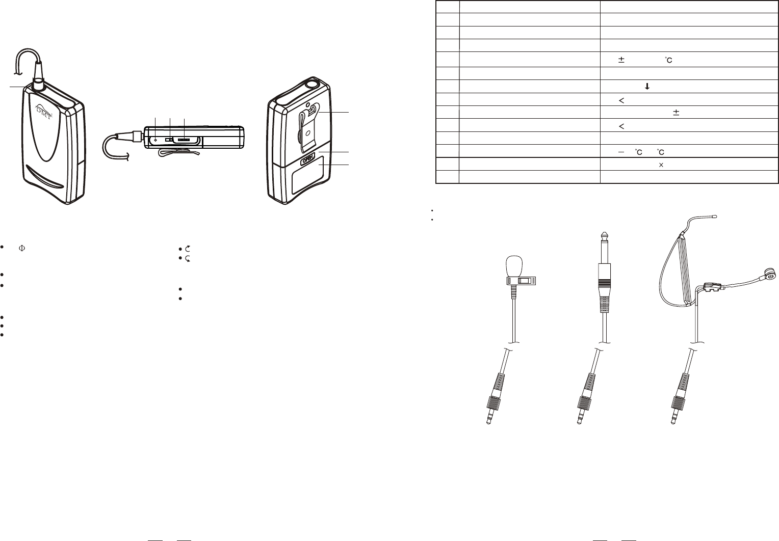
1. SOCKET
2. LED INDICATOR
3. POWER SWITCH
4. VOLUME CONTROL
5. BELT CLIP
6. BATTERY COVER
7. LABEL
4
3
2
7
5
6
7. LABEL
4. VOLUME CONTROL
Large
Small
2. LED INDICATOR
BATTER LOW
CHANGING BATTER WHEN
LIGHT-ON
5. BELT CLIP
2 WAYS FOR HANGING
VERTICAL
CROSSWISE
6. BATTERY COVER
OTHER FEATURES:
1. SOCKET
3.5 JACK
3. POWER SWITCH
ON
STAND BY
OFF
FEATURE:
1
DIAGRAM:
LS-66
LM-10 HM-28
1. BATTERY USE DC3V.
2. AVOID OF THROWING DOWN.
3. PROTECT THE UNITS AGAINST HUMIDITY AND HEAT.
4. IF THE UNITS ARE TO BE PUT OUT OF OPERATION DEFINITIVELY, BRING THEM TO
TECHNICAL ENGINEER FOR DISPOSAL.
CAUTION:
11
RR
6. LABEL6. LABEL
1. SOCKET
3.5 JACK
1. SOCKET
3.5 JACK
2. VOLUME CONTROL
Large
Small
2. VOLUME CONTROL
Large
Small
3. POWER SWITCH
ON
STAND BY
OFF
3. POWER SWITCH
ON
STAND BY
OFF
4. LED INDICATOR
BATTER LOW
CHANGING BATTER WHEN
LIGHT-ON
4. LED INDICATOR
BATTER LOW
CHANGING BATTER WHEN
LIGHT-ON
7. BELT CLIP
2 WAYS FOR HANGING
VERTICAL
CROSSWISE
7. BELT CLIP
2 WAYS FOR HANGING
VERTICAL
CROSSWISE
5. BATTERY COVER5. BATTERY COVER