SEIKAKU TECHNICAL GROUP WL-200R Wireless Microphone Receiver User Manual NF03650 WL 200R H P SHOW V1 3
SEIKAKU TECHNICAL GROUP LIMITED Wireless Microphone Receiver NF03650 WL 200R H P SHOW V1 3
Manual
SEIKAKU TECHNICAL GROUP
LIMITED
APR.16.2012
A3 A4 A5 3
SHOW
-RS
WL-200R/H SHOW_V1.3
WL-200R/H
0.035KG/1
105G NH00149(3:8)
6
NF03650
2V1.3
12/04/16
NO
1V1.2
11/10/24
User's Manual
WL-200R/H/P
WIRELESS
MICROPHONE SYSTEM
NF03650-1.3
SAFETY RELATED SYMBOLS
CAUTION
RISK OF ELECTRIC SHOCK
DO NOT OPEN
The symbol is used to indicate that
some hazardous live terminals are
involved within this apparatus, even
under the normal operating conditions.
The symbol is used in the service
documentation to indicate that specific
component shall be only replaced by
the component specified in that
Documentation for safety reasons.
Protective grounding terminal.
Alternating current /voltage.
ON: Denotes the apparatus turns on.
OFF: Denotes the apparatus turns off, bec-
ause of using the single pole switch, be sure
to unplug the AC power to prevent any
electric shock before you proceed your
service.
WARNING: Describes precautions that
should be observed to prevent the danger
of injury or death to the user.
CAUTION: Describes precautions that
should be observed to prevent danger of the
apparatus.
WARNING
Power Supply
Ensure the source voltage matches the
voltage of the power supply before turning
ON the apparatus.
Unplug this apparatus during lightning
storms or when unused for long periods
of time.
External Connection
The external wiring connected to the output
hazardous live terminals requires installation
by an instructed person, or the use of ready-
made leads or cords.
Do not Remove any Cover
There are maybe some areas with high
voltages inside, to reduce the risk of electric
shock, do not remove any cover if the power
supply is connected.
The cover should be removed by the qualified
personnel only.
No user serviceable parts inside.
Fuse
To prevent a fire, make sure to use fuses
with specified standard (current, voltage,
type). Do not use a different fuse or short
circuit the fuse holder.
Before replacing the fuse, turn OFF the
apparatus and disconnected the power
source.
Protective Grounding
Make sure to connect the protective
grounding to prevent any electric shock
before turning ON the apparatus.
Never cut off the internal or external pro-
tective grounding wire or disconnect the
wiring of protective grounding terminal.
Operating Conditions
Hazardous live terminal .
Disposing of this product should
not be placed in municipal waste
and should be separate collection.
This apparatus shall not be exposed to
dripping or splashing and that no objects
filled with liquids, such as vases, shall be
placed on this apparatus.
1
8
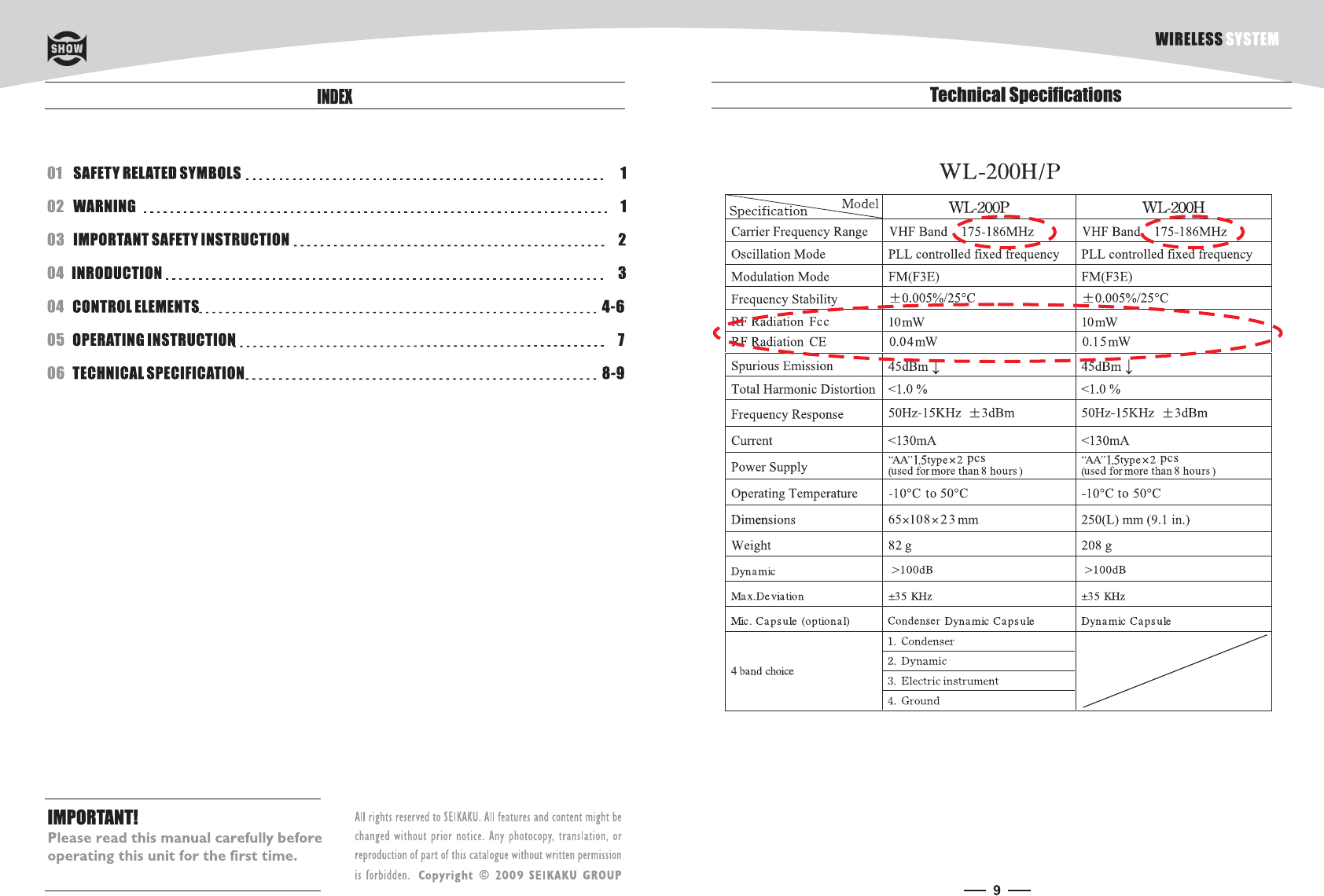
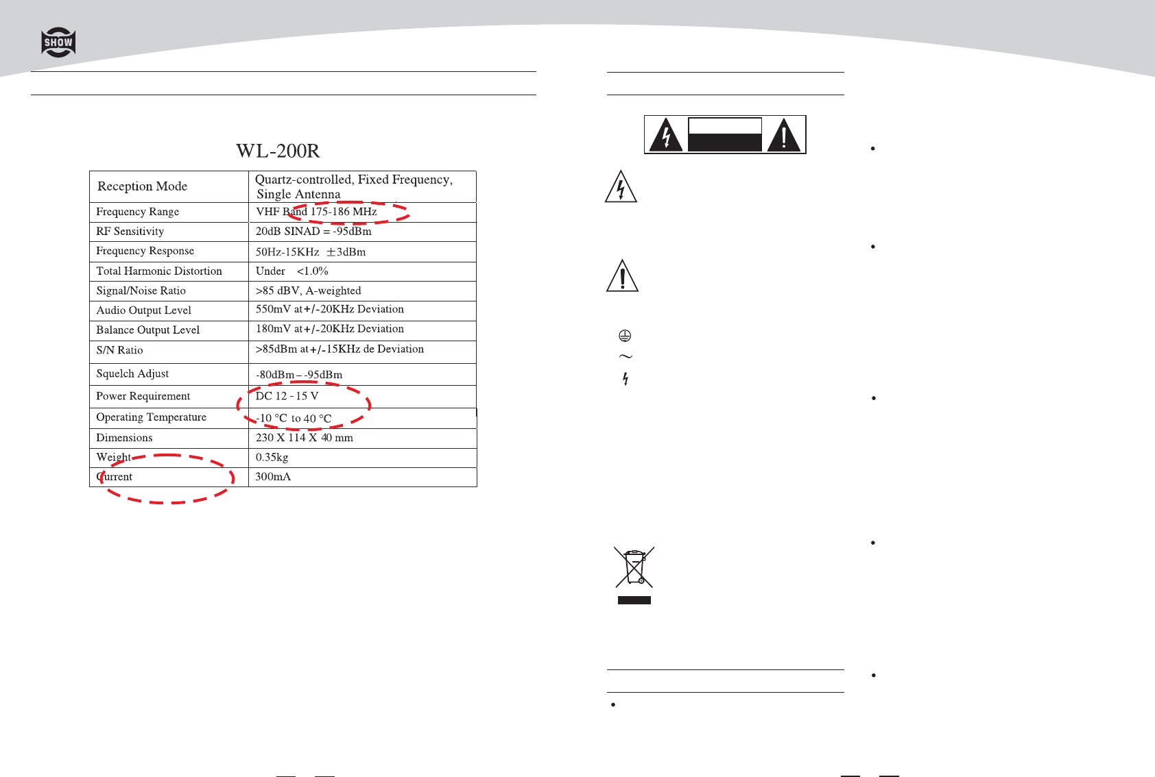
Technical Specifications
WIRELESS SYSTEM
2
Servicing
Refer all servicing to qualified personnel. To
reduce the risk of electric shock, do not
perform any servicing other than that
contained in the operating instructions unless
youarequalifiedtodoso.
Servicing is required when the apparatus has
been damaged in any way , such as power
supply cord or plug is damaged , liquid has
been spilled or objects have fallen into the
apparatus, the apparatus has been exposed
to rain or moisture , does not operate
normally, or has been dropped.
To reduce the risk of fire or electric shock,
do not expose this apparatus to rain or
moisture.
Do not use this apparatus near water.
Install in accordance with the manufacture-r's
instructions. Do not install near any heat
sources such as radiators, heat registers,
stoves, or other apparatus (including am-
plifiers) that produce heat. Do not block
any ventilation openings.
IMPORTANT SAFETY INSTRUCTIONS
Read these instructions.
Keep these instructions.
Heed all warnings.
Only use attachments/accessories spec-
ified by the manufacturer.
Power Cord and Plug
Do not defeat the safety purpose of the
polarized or grounding type plug.
A polarized plug has two blades with
one wider than the other. A grounding
type plug has two blades and a third
grounding prong. The wide blade or the
third prong are provided for your safety.
If the provided plug does not fit into your
outlet, consult an electrician for replace-
ment of the obsolete outlet.
Protect the power cord from being walk-
ed on or pinched particularly at plugs,
convenience receptacles, and the point
where they exit from the apparatus.
Cleaning
When the apparatus needs a cleaning, you
can blow off dust from the apparatus with
Follow all instructions.
No naked flame sources, such as lighted
candles, should be placed on the apparatus.
ablowerorcleanwithragetc.
Don't use solvents such as benzol, alcohol,
or other fluids with very strong volatility and
flammability for cleaning the apparatus body.
Clean only with dry cloth.
The mains plug is used as the disconnect device,
the disconnect device shall remain readily
operable.
Changes or modifications to this unit not
expressly approved by the party responsible
for compliance could void the user's authority
to operate the equipment.
NOTE: This equipment has been tested and
found to comply with the limits for a class B
digital device, pursuant to Part 15 of the FCC
Rules .These limits are designed to provide
reasonable protection against harmful
interference in a residential installation . This
equipment generates, uses and can radiate
radio frequency energy and , if not installed
SHOW wireless receivers are certified under FCC
Rules part 15 and transmitters are certified under
FCC Rules part 74.Licensing of SHOW equipment
is the user's responsibility and licensability depends
onthe user's classification,application and frequency
selected.
FCC Rules and Regulations
7
Operating Instruction
WL-200 consists of transmitter (microphone) and receiver.
Automatically calibrate frequency to match up the frequencies of microphone and receiver
1. Red LED, Orange LED and a push-button equipped at bottom
2. If red LED always lights up, it means that the transmitter (microphone) is muted; if the red
LED blinks, it means that the battery is of low level.
3. If the orange LED always illuminates, it means that the battery is of high level. If the orange LED
blinks, it means that the IR frequency calibration needs confirming.
4. Press the push-button to power on the unit; press and hold
the push-button 2 seconds to power off the unit. Press the MUTE button slightly, the volume
will be muted.
5. Frequency calibration
Align the bottom of the transmitter (microphone)to IR indicator of the receiver within distance
of 20cm until the orange LED at bottom of the transmitter (microphone) begins to blink. Then
press push-button at the bottom for confirm. The orange LED always illuminates, presenting
frequency calibration ok.
Transmitter (microphone) functions description
and hold the push-button 2 seconds
1. Press the SET button to manually set CH1~CH16 with corresponding LED on front panel
displaying 0~F.
2. Press the SCAN button to automatically calibrate the frequency.
3. Frequency calibration
Press the Scan button to automatically calibrate the IR frequencies. The receiver will automatically
search the available frequency and send the IR signal. The blinking LED means that it's searching
the signal. The LED will not stop blinking until the signal is received.
4.Up to 6 channels are available for the WL-200 without interference to each other. The six frequencies
are as follows: CH00,CH02,CH04,CHB,CH09,and CHD.
Receiver function description
WIRELESS SYSTEM
3
INTRODUCTION
Thanks for purchasing the SHOW wireless microphone system. The WL-200 is the delicately designed
VHF, PLL synthesized system, with antenna for smart switching diversity control, the higher level RF
signals maybe fed into the system for greater reliability and coverage, therefore, the risks of breakdown
and interference are to be effectively reduced.
The WL-200 features as follows:
-Switching diversity control to receive the RF signal;
-LED indication for RF, AF PEAK and POWER;
-Output volume control;
-Squelch control;
-Soft touch painting for comfortable use;
-Channel frequency adjusted manually
-PLL synthesized design;
-Consistent operating frequencies to comply with the EMC regulations;
-16 channel frequency presets;
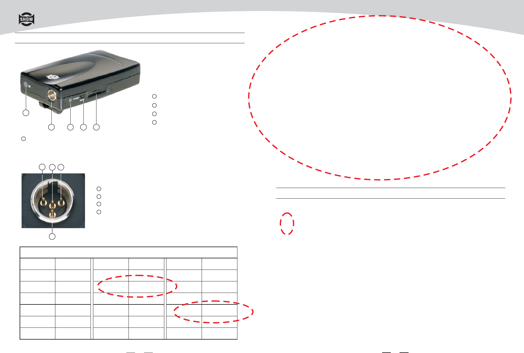
MINI 4P CONNECTOR
This connector is used to connect the unit with the clip microphones, for example, HM-38
or HM-58 condenser microphones.
C
A
1
2 3 4 5
D
B
Pin 1, GND
Pin 4, for Dynamic or condenser microphone
Pin 2, Phantom power supply for Condenser microphone
Pin 3, for Guitar, bass and keyboards
Channel Frequency
00 175.125MHz
01
02
03
04
05
175.375MHz
175.775MHz
175.975MHz
176.175MHz
176.525MHz
Channel Frequency
FREQUENCY TABLE
06 176.975MHz
07
08
09
A
B
177.925MHz
178.125MHz
178.925MHz
180.725MHz
181.525MHz
Channel Frequency
C 182.025MHz
D
E
F
183.225MHz
184.525MHz
185.125MHz
6
WL-200P
IR Receiving Section
1
Dual Colour LED
3
Power Switch/Mute
4
Volume Control
5
2
A
B
C
D
CONTROL ELEMENTS
WIRELESS SYSTEM
and used in accordance with the instructions,
may cause harmful interference to radio
communications. However, there is no
guarantee that interference will not occur in
a particular installation. If this
equipment does cause harmful interference
to radio or television reception, which
can be determined by turning the
equipment off and on, the user is
encouraged to try to correct the
interference by one or more of the following
measures:
--Reorient or relocate the receiving antenna.
--Increase the separation between the
equipment and receiver.
--Connect the equipment into an outlet on a
circuit different from that to which the
receiver is connected.
--Consult the dealer or an experienced radio/
TV technician for help.
This device complies with Part 15 of the FCC
Rules. Operation is subject to the following
two conditions:(1) this device may not cause
harmful interference and (2) this device must
accept any interference received. including
interference that may cause undesired
operation.
45
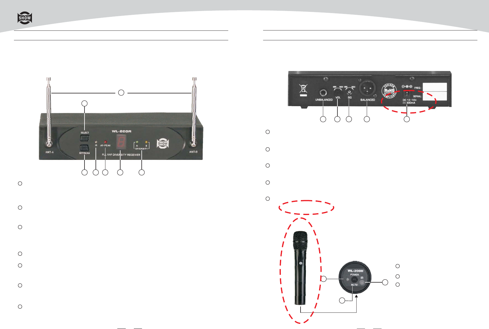
CONTROL ELEMENTS
FRONT PANEL
WL-200R
CONTROL ELEMENTS
WL-200H
REAR PANEL
1
It is the flexible antenna. To get effective transmission, never cover the antenna with hand ,
clothes, etc during the operation, and always position the transmitter nearby the receiver.
ANT-A & ANT-B
1
It is used to adjust the squelch level by using an adjusting bar which is placed in the microphone.
Squelch SWITCH
3
It is used to adjust the volume .
VOL SWITCH
2
This is a professional balanced XLR output connector.
XLR AUDIO OUTPUT
4
This is a professional unbalanced output jack.
AUDIO OUTPUT JACK
1
Connect 12V-15DC power supply to power on/off this unit.
DC IN
5
Diversity LED A & B
These two LED will light up when the ANT-A & ANT-B are used.
7
Display
This sexy and smart display will show exact Channel selected from 0~F, totally 16 channels.
6
SELECT button
Press the SET button to manually set CH1~CH16 with Display showing 0~F.
2
SET/SCAN
The SET button is used for selecting the desired frequency available and then press for
confirm. Press the SCAN button to automatically calibrate the frequency.
3
IR Transmitting Section
4
AF-peak
When this LED is illuminating, it means that the signal of the microphone is too strong.
5
76543
2
1
Power LED(dual colour LED)
2
Power Switch/Mute
3
IR Receiving Section
WIRELESS SYSTEM
13
2
1 4 52 3