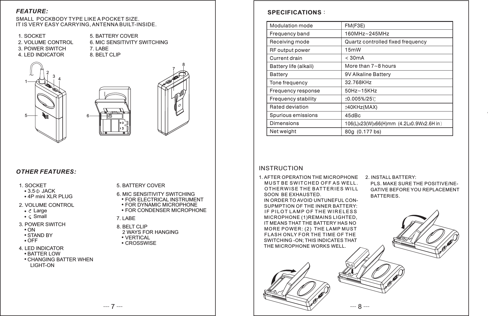
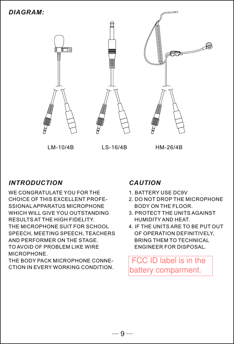
SEIKAKU TECHNICAL GROUP X-100H Handheld Transmitter User Manual X 100 200 V1 0 RS

SEIKAKU TECHNICAL GROUP LIMITED Handheld Transmitter X 100 200 V1 0 RS

Users Manual

IF YOU ARE NOT TECHNICALENGINEER PLS. DO NOTMODIFIED OR KNOCK - DOWNIT.NOTEWIRELESS SYSTEMINSTRUCTIONMANUALONVOLUME1VOLUME2POWERANTENNADual ReceiverANTENNA
1Specifications :Character :Special circuit design to delete microphone switch ON/OFF noise.Compression / Expanded circuit for extended dynamic range.LED Indicator (Power,RF,AF) and telescopic antenna.Compact, lightweight,single channel receiver.from 160-245 MHzVHF High band frequency by quartz locked controlled. RangeWeightDimensionsPower supplyOutput connectorAudio output levelReceiving modeFrequency responseS/N RatioDynamicT.H.D.Max. deviationModulation modeFrequency stabilityCarrier frequency rangeReceiving methodWith AC/DC adaptor 115/230V 50/60Hz226g152 98 36 mmDC 12V ~ 18V 200mAUnbalance 6.3 mm phone jackAt deviation = 40KHzUnbalance ,300mV , 10K loadWQuartz control fixed frequency50Hz-15KHz 3dB>90dB>100dB<1%40KHz,,with limiting compressFM (F3E)0.005% /25 CVHF Hi-Band 160-245MHzNon-diversity receiver25. Power Input Connect4. Audio Output Connector3. Telescopic Antenna2. VR And Therefore / Volume Control1. Power ON IndicatorNAMES OF PARTSFREQ.SERIAL1.4.5.2.3.
344. Power switch & volume control:off adjust the volume control tobe switched on and the volumeAdjust the volume control to"OFF"state, the unit will be powered"ON" direction, the power willcan also be contrtolled.VOLUME1VOLUME2POWERANTENNADual ReceiFIG.4a. Power ON Indicator:This red light glows when theDC supply and power SwitchON. It indicates that the rece-iver is on.b. Reception Indicator:This indicator does light duringstandby. When microphonesignal is received, The Blue indicatorlight to indicate the reception of microphone.MANUEL D'INSTRUCTION1. Install AntennaReceivers signals from the transmitter.Make sure the antenna is fullyextended vertically.INSTRUCTION MANUAL2.Audio Output ConnectorYou can connect an unbalancedaudio cable with a 1/4 inch phoneplug between this connector andyour mixer or amplifier input.FIG.1UNBALINFIG.2MIC / AUX INPUTFIG.312V-15VDCIN3. Power Supply ConnectionUse DC power supplycould switch with adaptorsupply or batter of12-18V DC.ConnectionDC supply ,DC plugconn-ection with "DC-IN"socket. (See FIG.3) anotherplug terminal connection withbattery or power supply.FREQ.SERIAL
54.Battery informationNote: Make sure the power switch is in the"OFF'position.When changing or installing new battery.For efficient use please install a new 9V alkali battery before usestandbyON6ON1.Feature:Quality capsule head make your sound performance more perfect2.Specification:hand-hold(1).Quartz locked controlModulation modeCarrier frequency rangeFrequency stabilityMAX. deviationPre-emphasisTHDRF powerFrequency rangeDynamic rangeBatteryCurrent consumptionBattery lifeDimensionsWork temperatureFM(F3E)160-245MHz0.005% 2540KHz50 S45dBc10mW50Hz-15KHz100dB9V30mA6-8hr.240cm-10 ~+603.Parts name:1/Grille holder2/Power LED3/Tube4/Color ring5/Neck ring6/Switch7/Switch cover8/Tail tube12345678  This device complies with Part 15 of the FCC Rules. Operation is subject to the following two conditions: (1) this device may not cause harmful interference, and (2) this device must accept any interference received,including interference that may cause undesired operation.
127835SENS1231. SOCKET2. VOLUME CONTROL3. POWER SWITCH4. LED INDICATOR5. BATTERY COVER6.7.8.MIC SENSITIVITY SWITCHINGLABEBELT CLIP46FEATURE:SMALL POCKBODY TYPE LIKE A POCKET SIZE.IT IS VERY EASY CARRYING, ANTENNA BUILT-INSIDE.OTHER FEATURES:7. LABE1. SOCKET3.5 JACK4P mini XLR PLUG2. VOLUME CONTROLLargeSmall3. POWER SWITCHONSTAND BYOFF4. LED INDICATORBATTER LOWCHANGING BATTER WHENLIGHT-ON6. MIC SENSITIVITY SWITCHINGFOR ELECTRICAL INSTRUMENTFOR DYNAMIC MICROPHONEFOR CONDENSER MICROPHONE8. BELT CLIP2 WAYS FOR HANGINGVERTICALCROSSWISE5. BATTERY COVER1. AFTER OPERATION THE MICROPHONEMUST BE SWITCHED OFF AS WELL.OTHERWISE THE BATTERIES WILLSOON BE EXHAUSTED.IN ORDER TO AVOID UNTUNEFUL CON-SUPMPTION OF THE INNER BATTERY:IF PILOT LAMP OF THE WIRELESSMICROPHONE (1)REMAINS LIGHTED,IT MEANS THAT THE BATTERY HAS NOMORE POWER: (2) THE LAMP MUSTFLASH ONLY FOR THE TIME OF THESWITCHING -ON; THIS INDICATES THATTHE MICROPHONE WORKS WELL.INSTRUCTION2. INSTALL BATTERY:PLS. MAKE SURE THE POSITIVE/NE-GATIVE BEFORE YOU REPLACEMENTBATTERIES.SPECIFICATIONSFM(F3E)160MHz~245MHzQuartz controlled fixed frequencyModulation modeFrequency bandReceiving modeRF output powerCurrent drainBattery life (alkali)BatteryTone frequencyFrequency responseFrequency stabilityRated deviationSpurious emissionsDimensionsNet weight45dBc106(L) 23(W) 66(H)mm (4.2L 0.9W 2.6H in80g (0.177 bs)15mW<30mAMore than 7~8 hours9V Alkaline Battery32.768KHz50Hz~15KHz0.005%/2540KHz(MAX)78
WE CONGRATULATE YOU FOR THECHOICE OF THIS EXCELLENT PROFE-SSIONAL APPARATUS MICROPHONEWHICH WILL GIVE YOU OUTSTANDINGRESULTS AT THE HIGH FIDELITY.THE MICROPHONE SUIT FOR SCHOOLSPEECH, MEETING SPEECH, TEACHERSAND PERFORMER ON THE STAGE.TO AVOID OF PROBLEM LIKE WIREMICROPHONE.THE BODY PACK MICROPHONE CONNE-CTION IN EVERY WORKING CONDITION.1. BATTERY USE DC9V2. DO NOT DROP THE MICROPHONEBODY ON THE FLOOR.3. PROTECT THE UNITS AGAINSTHUMIDITY AND HEAT.4. IF THE UNITS ARE TO BE PUT OUTOF OPERATION DEFINITIVELY,BRING THEM TO TECHNICALENGINEER FOR DISPOSAL.INTRODUCTION CAUTIONLS-16/4BLM-10/4B HM-26/4BDIAGRAM:9 FCC ID label is in the battery comparment.

Navigation menu