SEIKAKU TECHNICAL GROUP X-100H Handheld Transmitter User Manual X 100 200 V1 0 RS
SEIKAKU TECHNICAL GROUP LIMITED Handheld Transmitter X 100 200 V1 0 RS
Users Manual
IF YOU ARE NOT TECHNICAL
ENGINEER PLS. DO NOT
MODIFIED OR KNOCK - DOWN
IT.
NOTE
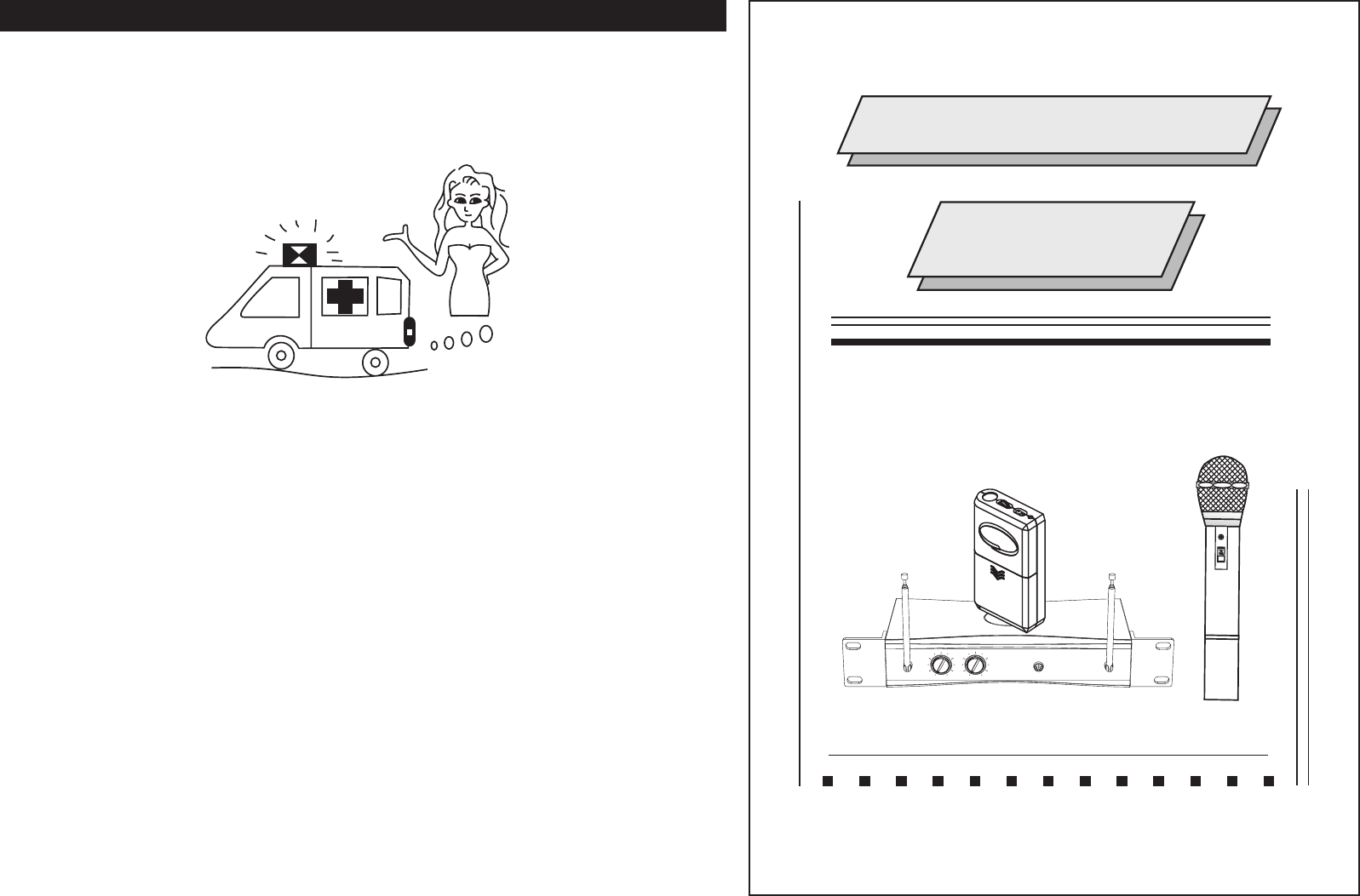
WIRELESS SYSTEM
INSTRUCTION
MANUAL
ON
VOLUME1
VOLUME2
POWER
ANTENNA
Dual Receiver
ANTENNA
1
Specifications :
Character :
Special circuit design to delete microphone switch ON/OFF noise.
Compression / Expanded circuit for extended dynamic range.
LED Indicator (Power,RF,AF) and telescopic antenna.
Compact, lightweight,single channel receiver.
from 160-245 MHz
VHF High band frequency by quartz locked controlled. Range
Weight
Dimensions
Power supply
Output connector
Audio output level
Receiving mode
Frequency response
S/N Ratio
Dynamic
T.H.D.
Max. deviation
Modulation mode
Frequency stability
Carrier frequency range
Receiving method
With AC/DC adaptor 115/230V 50/60Hz
226g
152 98 36 mm
DC 12V ~ 18V 200mA
Unbalance 6.3 mm phone jack
At deviation = 40KHz
Unbalance ,300mV , 10K loadW
Quartz control fixed frequency
50Hz-15KHz 3dB
>90dB
>100dB
<1%
40KHz,,with limiting compress
FM (F3E)
0.005% /25 C
VHF Hi-Band 160-245MHz
Non-diversity receiver
2
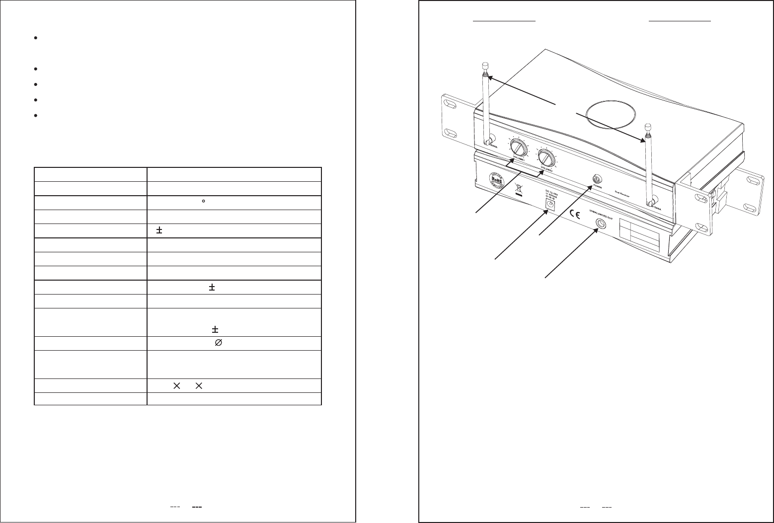
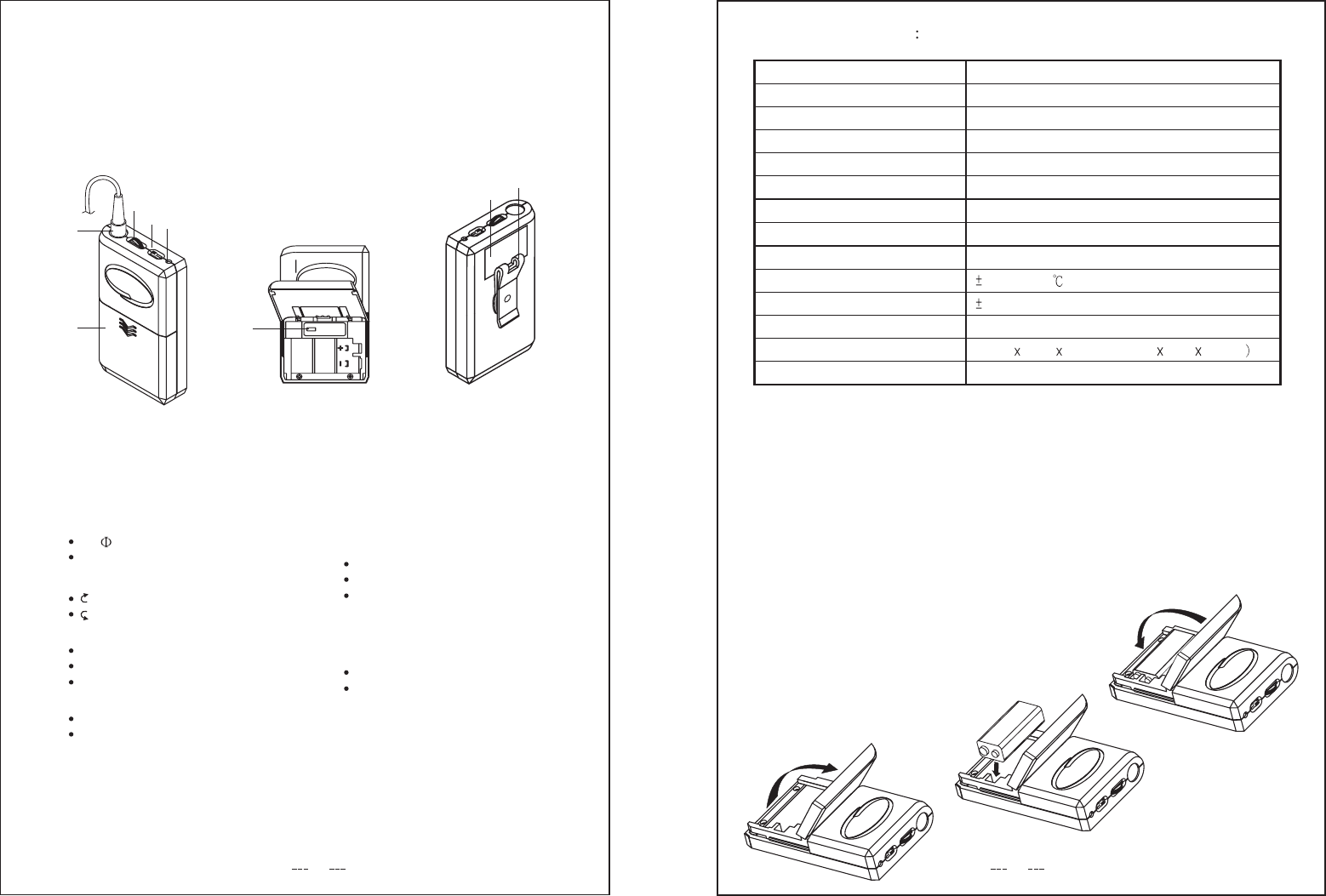
5. Power Input Connect
4. Audio Output Connector
3. Telescopic Antenna
2. VR And Therefore / Volume Control
1. Power ON Indicator
NAMES OF PARTS
FREQ.
SERIAL
1.
4.
5.
2.
3.
34
4. Power switch & volume control:
off adjust the volume control to
be switched on and the volume
Adjust the volume control to"OFF"
state, the unit will be powered
"ON" direction, the power will
can also be contrtolled.
VOLUME1
VOLUME2
POWER
ANTENNA
Dual Recei
FIG.4
a. Power ON Indicator:
This red light glows when the
DC supply and power Switch
ON. It indicates that the rece-
iver is on.
b. Reception Indicator:
This indicator does light during
standby. When microphone
signal is received, The Blue indicator
light to indicate the reception of microphone.
MANUEL D'INSTRUCTION
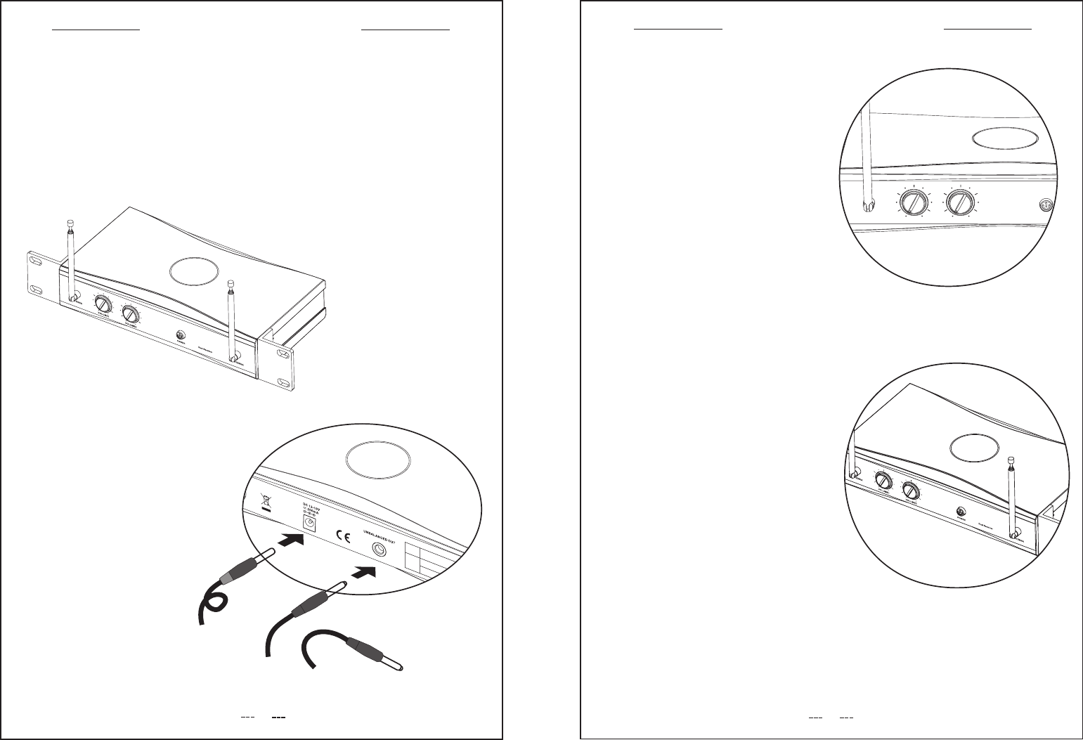
1. Install Antenna
Receivers signals from the transmitter.
Make sure the antenna is fully
extended vertically.
INSTRUCTION MANUAL
2.Audio Output Connector
You can connect an unbalanced
audio cable with a 1/4 inch phone
plug between this connector and
your mixer or amplifier input.
FIG.1
UNBAL
IN
FIG.2
MIC / AUX INPUT
FIG.3
12V-15V
DC
IN
3. Power Supply Connection
Use DC power supply
could switch with adaptor
supply or batter of
12-18V DC.Connection
DC supply ,DC plug
conn-ection with "DC-IN"
socket. (See FIG.3) another
plug terminal connection with
battery or power supply.
FREQ.
SERIAL
5
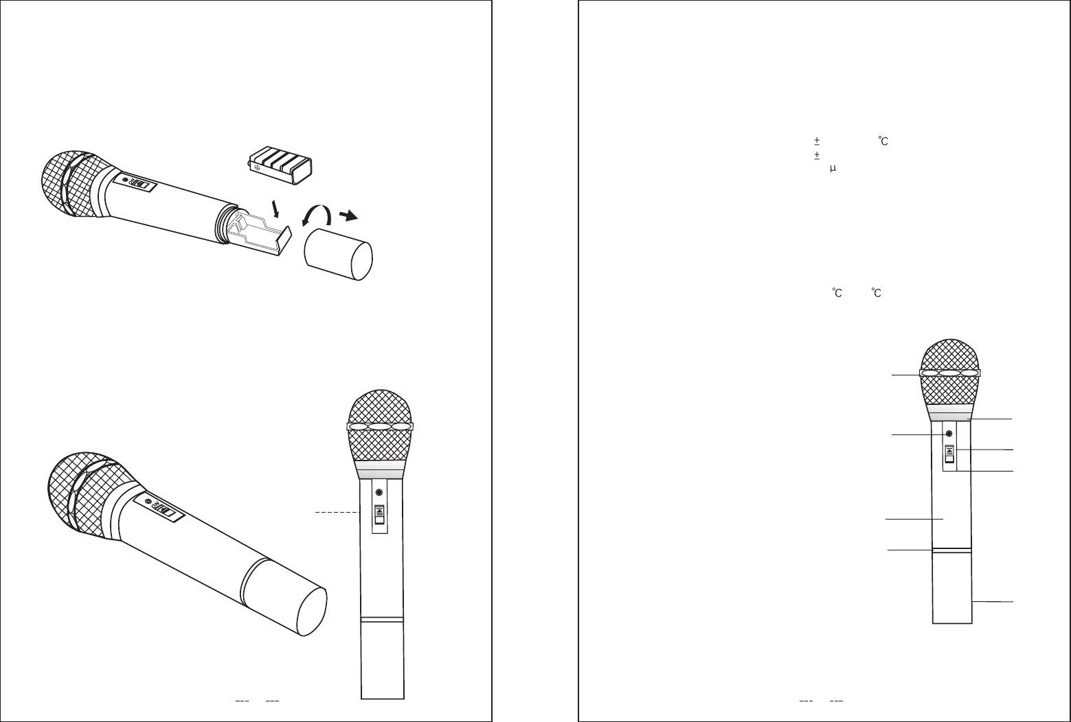
4.Battery information
Note: Make sure the power switch is in the"OFF'position.
When changing or installing new battery.
For efficient use please install a new 9V alkali battery before use
standby
ON
6
ON
1.Feature:
Quality capsule head make your sound performance more perfect
2.Specification:hand-hold
(1).Quartz locked control
Modulation mode
Carrier frequency range
Frequency stability
MAX. deviation
Pre-emphasis
THD
RF power
Frequency range
Dynamic range
Battery
Current consumption
Battery life
Dimensions
Work temperature
FM(F3E)
160-245MHz
0.005% 25
40KHz
50 S
45dBc
10mW
50Hz-15KHz
100dB
9V
30mA
6-8hr.
240cm
-10 ~+60
3.Parts name:
1/Grille holder
2/Power LED
3/Tube
4/Color ring
5/Neck ring
6/Switch
7/Switch cover
8/Tail tube
1
2
3
4
5
6
7
8
This device complies with Part 15 of the
FCC Rules. Operation is subject to the
following two conditions: (1) this device
may not cause harmful interference, and
(2) this device must accept any
interference received,including interference
that may cause undesired operation.
1
27
8
3
5
SENS
123
1. SOCKET
2. VOLUME CONTROL
3. POWER SWITCH
4. LED INDICATOR
5. BATTERY COVER
6.
7.
8.
MIC SENSITIVITY SWITCHING
LABE
BELT CLIP
4
6
FEATURE:
SMALL POCKBODY TYPE LIKE A POCKET SIZE.
IT IS VERY EASY CARRYING, ANTENNA BUILT-INSIDE.
OTHER FEATURES:
7. LABE
1. SOCKET
3.5 JACK
4P mini XLR PLUG
2. VOLUME CONTROL
Large
Small
3. POWER SWITCH
ON
STAND BY
OFF
4. LED INDICATOR
BATTER LOW
CHANGING BATTER WHEN
LIGHT-ON
6. MIC SENSITIVITY SWITCHING
FOR ELECTRICAL INSTRUMENT
FOR DYNAMIC MICROPHONE
FOR CONDENSER MICROPHONE
8. BELT CLIP
2 WAYS FOR HANGING
VERTICAL
CROSSWISE
5. BATTERY COVER
1. AFTER OPERATION THE MICROPHONE
MUST BE SWITCHED OFF AS WELL.
OTHERWISE THE BATTERIES WILL
SOON BE EXHAUSTED.
IN ORDER TO AVOID UNTUNEFUL CON-
SUPMPTION OF THE INNER BATTERY:
IF PILOT LAMP OF THE WIRELESS
MICROPHONE (1)REMAINS LIGHTED,
IT MEANS THAT THE BATTERY HAS NO
MORE POWER: (2) THE LAMP MUST
FLASH ONLY FOR THE TIME OF THE
SWITCHING -ON; THIS INDICATES THAT
THE MICROPHONE WORKS WELL.
INSTRUCTION
2. INSTALL BATTERY:
PLS. MAKE SURE THE POSITIVE/NE-
GATIVE BEFORE YOU REPLACEMENT
BATTERIES.
SPECIFICATIONS
FM(F3E)
160MHz~245MHz
Quartz controlled fixed frequency
Modulation mode
Frequency band
Receiving mode
RF output power
Current drain
Battery life (alkali)
Battery
Tone frequency
Frequency response
Frequency stability
Rated deviation
Spurious emissions
Dimensions
Net weight
45dBc
106(L) 23(W) 66(H)mm (4.2L 0.9W 2.6H in
80g (0.177 bs)
15mW
<30mA
More than 7~8 hours
9V Alkaline Battery
32.768KHz
50Hz~15KHz
0.005%/25
40KHz(MAX)
78
WE CONGRATULATE YOU FOR THE
CHOICE OF THIS EXCELLENT PROFE-
SSIONAL APPARATUS MICROPHONE
WHICH WILL GIVE YOU OUTSTANDING
RESULTS AT THE HIGH FIDELITY.
THE MICROPHONE SUIT FOR SCHOOL
SPEECH, MEETING SPEECH, TEACHERS
AND PERFORMER ON THE STAGE.
TO AVOID OF PROBLEM LIKE WIRE
MICROPHONE.
THE BODY PACK MICROPHONE CONNE-
CTION IN EVERY WORKING CONDITION.
1. BATTERY USE DC9V
2. DO NOT DROP THE MICROPHONE
BODY ON THE FLOOR.
3. PROTECT THE UNITS AGAINST
HUMIDITY AND HEAT.
4. IF THE UNITS ARE TO BE PUT OUT
OF OPERATION DEFINITIVELY,
BRING THEM TO TECHNICAL
ENGINEER FOR DISPOSAL.
INTRODUCTION CAUTION
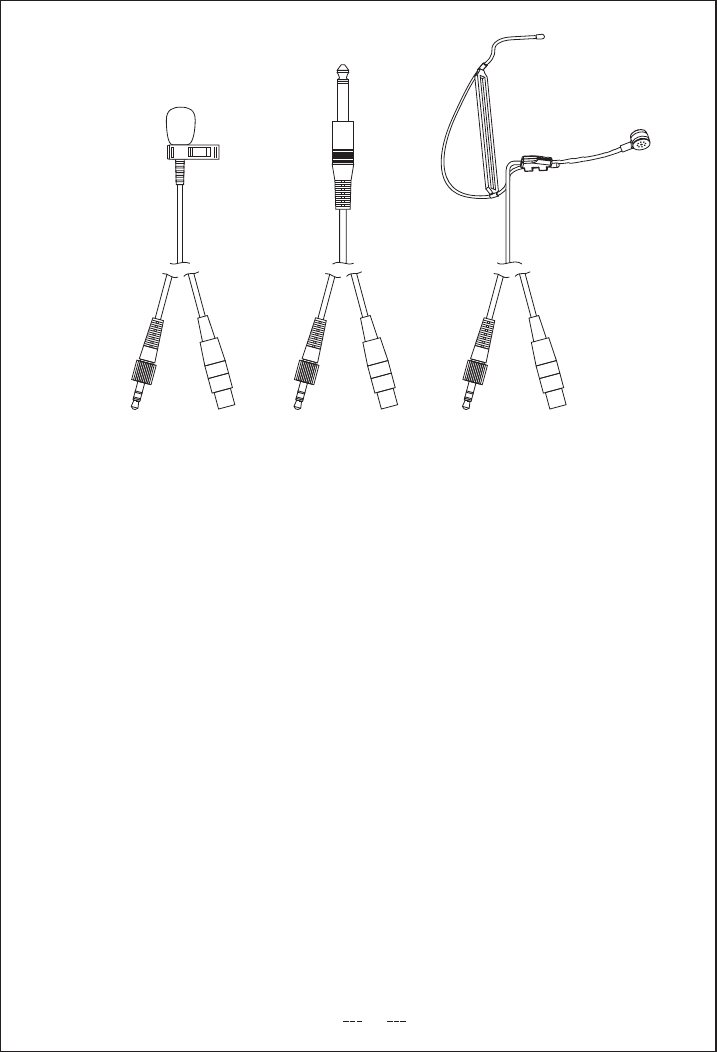
LS-16/4BLM-10/4B HM-26/4B
DIAGRAM:
9
FCC ID label is in the
battery comparment.